

Page 1
CMR Electrical Ltd
BoltonHouse
Five Chimneys Lane
Hadlow Down
East Sussex
TN22 4DX
Tel: 01825 733600
DMWD
1 to 4 Zone Water Detection
Alarm with Distance to Leak
Measurement
Installation and Operation
Manual
Page 2

2
Contents
1) Display and Control
2) Operation
3) Water leak detected Alarm Test
4) Water Detected Alarm
5) Sensor Fault
6) Water Detection Sensitivity Adjustment
7) Installation
8) Positioning the water detection cable
9) Fitting Cable clips
10) Water Shutdown Valve
11) Water Shutdown Valve Override Procedure
12) Beacon and beacon sounder
13) Fitting the battery backup
14) Commissioning
15) Fault Diagnosis
16) Installation Drawing
17) Housing Size
Page 3
3
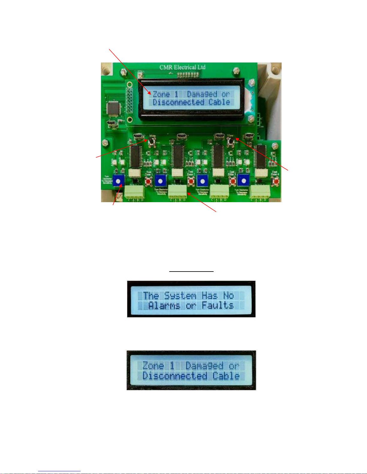
1) Display and Control
Display Screens
a) All detection cables are connected correctly and a water leak has not detected
b) The detection cable has been disconnected, unplugged, damaged or cut
Zone Status
Display
Mute Alarm Push
Button
Valve Shutdown
Override &
Display Cable
Length Button
Zone Sensitivity
Adjustment see
Item 6 below
Removable Terminal Block
for connection to the water
detection cable or sensor
Page 4
4
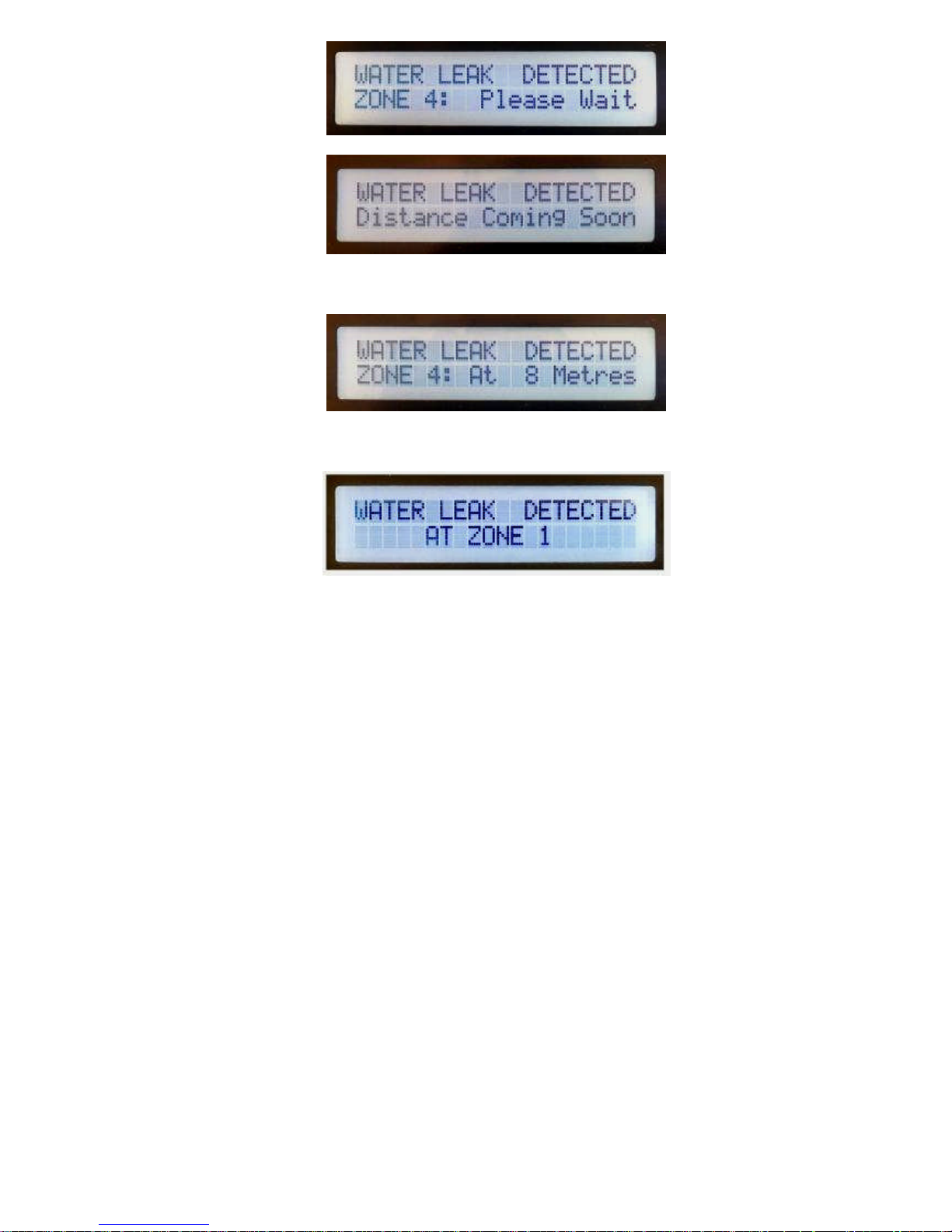
c) When the display is rotating between the above two windows, water has been detected and the unit is
calculating the distance to the leak
d) After (c) above, the display will change to show the distance to the leak from the start of the water
detection cable.
e) A leak has been detected but the zone is either not set for a distance reading, was unable to calculate
the cable length on power up due to water or contaminants in the cable, or encountered a problem in
determining the distance to the leak.
2) Operation
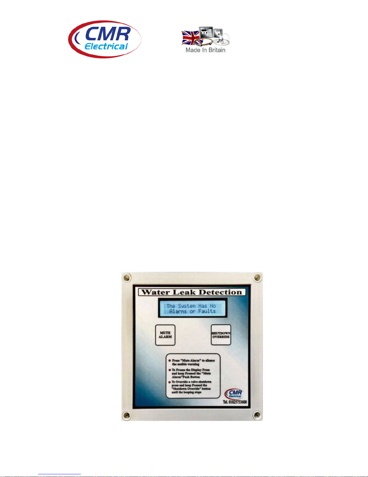
In normal operation with no alarms or faults, the audible warning device will be OFF and the display will
be showing “The System has no Alarms or Faults”. If one or more of the zones has a disconnected or
damaged cable, the audible warning device will sound and the display will show “ Zone (1-2-3-4)
Damaged or Disconnected Cable”. If the detection cable detects water, the audible warning device will
sound and the display will alternate between “WATER LEAK DETECTED ZONE (1-2-3-4) Please
Wait” and “WATER LEAK DETECTED Distance Coming Soon” until the final display window showing
the distance to the leak “WATER LEAK DETECTED ZONE (1-2-3-4) At 8 Metres”. The display
window “WATER LEAK DETECTED AT ZONE (1-2-3-4) will be displayed on powering up if the
system cant determine the total detection cable length due to water or contaminants touching the cable.
This window will also be displayed if the system cant determine the distance to the leak or the zone is not
set for distance measurement. If water shutoff valves are fitted, if a zone detects water, the appropriate
valve will close and the associated internal “Closed” lamp will illuminate. The system will automatically
open the valve allowing water to flow once the zone stops detecting water. This shutdown can be
overridden, See Item 11 below .
The length of the water detection cable can be checked providing the system has no alarms or faults as
shown in screen (a) on page 3. To check the cable lengths press the “Override / View” push button. Each
cable length will be displayed one at a time.
If the system has multiple alarms, the screen will automatically scroll between each alarm one after the
other providing the current alarm has been muted. This scrolling can be stopped at any time by
continually pressing the “Mute” push button. If multiple alarms occur at the same time, each alarm will
need acknowledging by the press of the “Mute” button. i.e. zones 1 & 2 go into water detected alarm at
Page 5
5
the same time, the audible warning will be going with “Zone 1 water detected” on display. Pressing
“Mute” will stop the audible warning but it will immediately start again only this time the display will be
showing “Zone 2 water detected”. This second alarm will also need the “mute” button operated to silence
the audible warning. For ease of installation and fault diagnoses both individual zone “Alarm” and “Fault
lamps have been provided internally on the top PCB.
3) Water leak detected Alarm Test
To test that the unit is functioning correctly, pressing the red “Test Zone” button to put the system into a
Water detected alarm. Using the test facility will operate the alarm relays generating a BMS alarm, and if
fitted activate of the remote beacon/sounder and close the water shutoff valve. The resulting screen can be
either (d) or (e) as shown on page 3. The displayed distance if any will be fictional.
4) Water Detected Alarm
When the detection cable comes into contact with water anywhere along its length, the audible warning
device will start, the common alarm and if fitted, the zone alarm relay will close and the display will show
the zone number and distance to the leak from the start of the detection cable. To stop the audible warning
press the “Mute Alarm” button. The system will remain in this state until the water has been removed
from the cable when the alarm relay will automatically turn OFF.
5) Sensor Fault
Because of the exposure of the detection cable on the floor, the system monitors for any breaks in the
detection cable including the interconnection cable between the control unit and the detection cable. If a
break within the cable is found, the audible warning device will start, the fault relay will operate and the
display will show the zone number. To stop the audible warning press the “Mute Alarm” push button. The
system will remain in this state until the sensor fault is repaired when the display and common fault relay
will revert back to normal. If the controller detects a break in the cable, the system will continue to detect
water up to the point of the break.
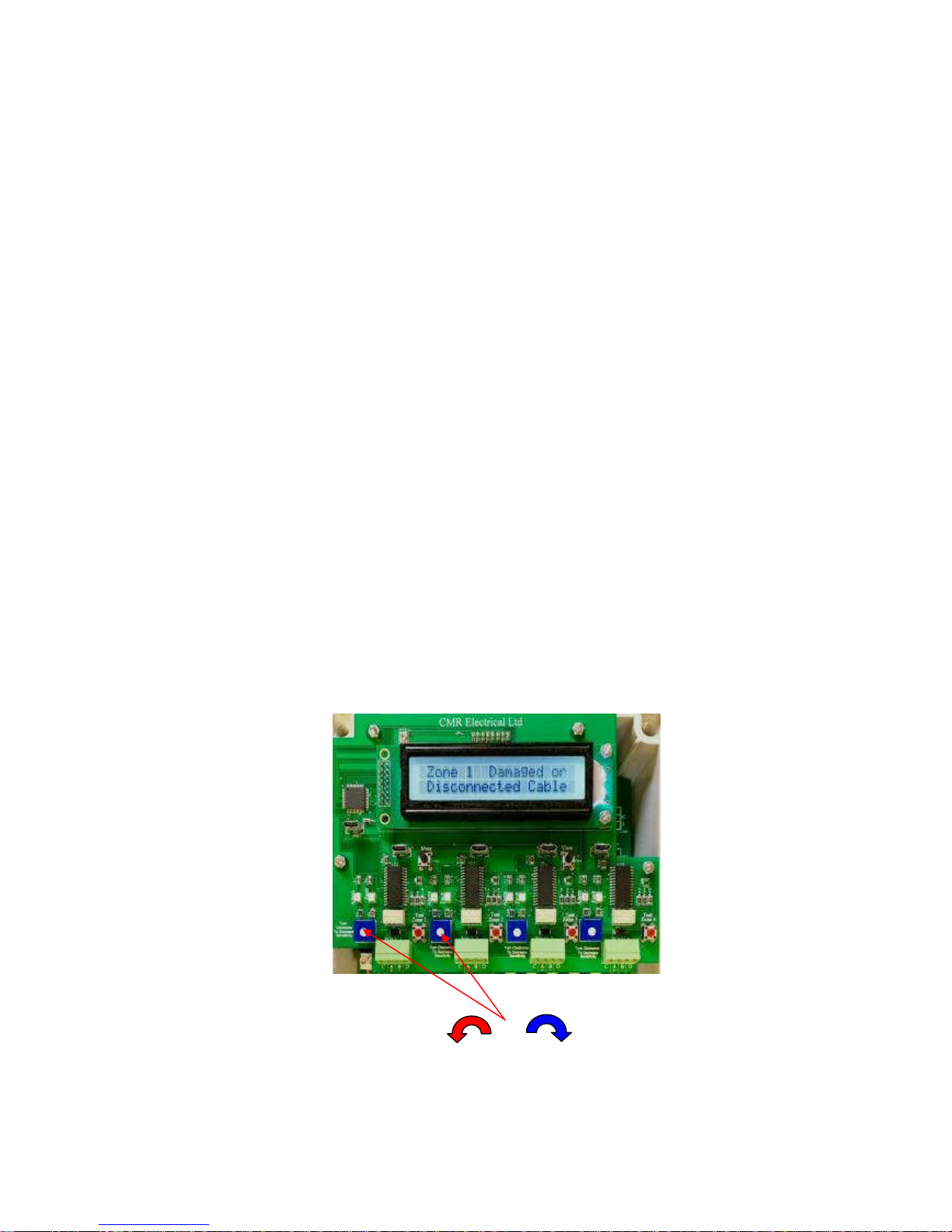
6) Water Detection Sensitivity Adjustment
To increase the sensitivity of the cable turn the potentiometer ANTICLOCKWISE, to de-crease the
sensitivity turn CLOCKWISE.
The sensitivity adjustment is provided to allow the point at which the system goes into alarm to be
adjusted. Once the system is in alarm the cable will need to be dry before any reset. It is recommended
that the sensitivity be set so that the arrow on the white plastic circle as shown above is pointing at the
3:00 clock position
Increase Sensitivity Decrease Sensitivity
Page 6

6
7) Installation
THIS EQUIPMENT SHOULD ONLY BE CONNECTED AND WORKED ON BY A QUALIFIED
ELECTRICIAN.
To mount the unit to a wall, first remove the front cover to expose the internal equipment. In each corner
of the housing positioned below/above the front cover fixings will be found the mounting holes.
Plastic glands have been provided for incoming power and outgoing signal cables. The large gland
requiring a 20mm hole within the housing is for the power cable and the smaller gland requiring a 13mm
hole within the housing is for the signal cable. Care should be taken when drilling the holes to ensure no
damage occurs to the electronic equipment.
A suitably rated 230VAC power cable supply should be run from a fused spur to the unit and terminated
to the internal terminal block marked “L”, “E” & “N”. The fuse within the fused spur should be rated at 5
Amps.
Distance Measuring Signal Cable Connections
White signal cable
Red wire to "A +", Black wire to "B -", Yellow wire to “C”, Blue wire to “D”
End of line
Terminator
Plug MUST
Be fitted at the
end of the
detection cable
Terminate the Red,
Black, Yellow and
Blue wires to the
terminals within
The alarm housing
as shown above
Water leak
detection Cable
run around the
area to be
protected
Signal cable
used to connect the water
detection cable to the alarm unit
Signal cable to
Water detection
cable connectors
Page 7

7
Non Distance Measuring Signal Cable Connections
Power, Shutdown Valves and BMS Connections
If Fitted
230VAC
To Zone 1
Shutdown
Valve
If Fitted
230VAC
To Zone 2
Shutdown
Valve
If Fitted
Zone 1
Output
Alarm
Contact
If Fitted
Zone 2
Output
Alarm
Contact
Common
Alarm
Output
Alarm
Contact
Common
Fault
Output
Alarm
Contact
230VAC SUPPLY
If Fitted
230VAC
To Zone 3
Shutdown
Valve
If Fitted
230VAC
To Zone 4
Shutdown
Valve
If Fitted
Zone 3
Output
Alarm
Contact
If Fitted
Zone 4
Output
Alarm
Contact
White signal cable
Red wire to "A +", Black wire to "B -"
End of line
Terminators
Plug MUST
Be fitted at the
end of the
detection cable
Terminate the Red
and Black wires to
the terminals within
The alarm housing
as shown above
Water leak
detection Cable
run around the
area to be
protected
Signal cable
used to connect to the
water detection cable to
the alarm unit terminals
Signal cable to
Water detection
cable connectors
Page 8

8
Output Volt Free contacts for use by a Building Management System.
Function Required Fitted as Standard Relay Output Terminals
Zone 1 alarm No Z1 Alarm
Zone 2 alarm No Z2 Alarm
Zone 3 alarm No Z3 Alarm
Zone 4 alarm No Z4 Alarm
Water detected alarm any zone Yes Common Alarm
Cable Disconnected Alarm Yes Common Fault
Power Fault Yes Common Fault
All Zone wiring and volt free alarm / fault relays wiring is to removable screw type terminal blocks.
8) Positioning the water detection cable
The detection cable is susceptible to damage and should not be fitted to areas where the cable is likely to
be damaged or walked on. If fitting the cable around Air Conditioning Units with humidifiers, ensure that
cable is positioned at least one metre from the ACU to stop intermittent alarms being generated from over
humidity or water droplets from the AHU. Having positioned the detection cable, ensure that the End of
line terminator is plugged into the end of the cable (see drawing above).
9) Fitting Cable Clips
If Cable Clips are required, to protect the small sensor wires and to stop false water detected alarms from
occurring insulating tape should be first applied around the detection cable before the clip tongue is
closed. Clips should be fitted approximately every 1 to 1.5 metres apart. When using clips make sure that
the cable touches the floor between the clips, DO NOT tighten the cable so that the cable does not touch
the floor.
10) Water Shutdown Valve
If the system is supplied with water shutoff valves, once a water leak has been detected the unit will
remove the 230V supply holding open the valve thereby closing it and stopping the flow of water. Once
the leak has been rectified the detection cable may take some hours to dry out. During the dry out period
the valve can be opened and closed using the procedure outlined in Item 11 below.
Insulating Tape
Under the fixing
clip tongue
Page 9

9
Connection of Water Shutdown Ball Valve
The Valve is supplied with a short length of cable that will need extending back to the Valve terminals
within the alarm unit.
WARNING, In order to shut properly, this type of valve need powering for at least 3 minutes.
Connection of Water Shutdown Solenoid Valve
PLEASE NOTE;
The type of valve MUST be fitted with the arrow on its body facing the direction of flow, if not, the
valve will not stop the flow of water.
11) Water Shutdown Valve Override Procedure
This future will only work if there is a current water leak detected alarm, the zone has not already been
overridden and the alarm has been Muted. To put the system into shutdown override and re-open the
water valve, press and keep pressed the “Shutdown Override” push button. On pressing the button the
unit will start beeping. Keeping the finger on the button and wait until the beeping to stops. Once this
happens stop pressing the Mute button. The system will automatically cancel the override once the zone
stops detecting a water leak. If the Override needs cancelling and the valve needs to be closed again,
Press the “Shutdown Override” button again and following the same procure will cancel the override and
close the shutdown valve.
The 230VAC supply to
the valves is generated
from within the alarm
unit. 15 to 25mm valves
are supplied with a red
and black cable whilst
larger valves are red and
green. For good practice
connect live to the red
wire and neutral to the
black or green wire.
The 230VAC supply to
the valves is generated
from within the alarm
unit.
Having removed and
opened the 3 pin socket,
connect live to terminal
“1”, neutral to terminal
“2” and Earth to the earth
terminal
Page 10

10
12) Beacon and beacon sounder
If a beacon or beacon sounder is supplied connect to the three terminals identified as “Sounder Beacon”
as follows.
12a) Non Mutable Beacon or beacon sounder
If the beacon or the beacon sounder is to be active (On all the time) until the water leak alarm has
cleared, connect as follows
Terminal
reference
Connect Beacon / beacon sounder
terminals to the following terminals
+V Beacon +V or Strobe /Tone + terminal
BOV Beacon -V or Strobe /Tone - terminal
SOV NO connection to this terminal
12b) Mutable Beacon or beacon sounder
If the beacon or the beacon sounder is to turn off when the “Mute” push button is pressed connect
as follows.
Terminal
reference
Connect Beacon / beacon sounder
terminals to the following terminals
+V Beacon +V or Strobe /Tone + terminal
BOV NO connection to this terminal
SOV Beacon -V or Strobe /Tone - terminal
12c) Mutable sounder Beacon on all the time
If the beacon is to remain alight all the time an alarm is current but the sounder is to be turned off
when the “Mute” push button is pressed connect as follows.
Terminal
reference
Connect Beacon / beacon sounder
terminals to the following terminals
+V Strobe and Tone + terminal
BOV Strobe - terminal
SOV Tone - terminal
Warning; if the above option “12c” is required, remove the electrical link connected between the second
(Strobe -) & third terminals (Tone -) terminals within the sounder.
Sounder
Beacon
terminal
block
Zone 1-2-3 & 4 Shutdown valve closed lamps
Page 11

11
13) Fitting the battery backup
The battery should be fitted connected after the system as been commissioned. Place the battery within
the housing in the space provided. Connect the small BLACK cable to the “—“ battery terminal and the
RED with black dots wire to the batteries “+” terminal. If the battery is misconnected, the battery fuse
located on the small PCB will blow.
14) Commissioning
The unit will automatically calculate the total cable length each time it is power up. For this reason
the unit MUST be clear of all alarms and faults. If the total cable length cant be calculated due to
contaminants or water in the detection cable, the system will revert back to a standard water
detection system with NO measurement to the leak. However, once the cable dries out the system
will again automatically calculate the total detection cable length without the need of powering
down the unit.
Having connected the unit as described above, turn on the mains power to the unit. The display should
display the following screen. If not, refer to the “Fault Diagnostics” below. If the unit powers up with the
audible warning going, press the mute button and wait to see if the alarm clears. If the alarm remains after
approximately 20 seconds , refer to the “Fault Diagnostics” below.
Note; Before the system can be commissioned and tested, the alarm unit must be displaying this screen.
With the unit powered and displaying the above screen, press the “Override / View” push button and
check each zones cable length is correct.
Next unplug the End of line terminator positioned at the end of the detection cable. The controller should
display “Zone (1-2-3-4) Damaged or Disconnected Cable” and the audible warning device should sound,
if not refer to the “Fault Diagnostics” below, press the “Mute” button, the audible warning device should
stop. Replace the End of line terminator to return the system to normal.
Using a cup of CLEAN water, immerse a small area (75mm long) of cable into the water. The controller
should alternate between the following two screens.
Page 12

12
Once the unit calculates the distance to the leak, the display will change to the following and the audible
warning device should sound, if not refer to the “Fault Diagnostics” below. Press the “Mute” button the
audible warning device should stop.
Remove the water and wipe the cable with some tissue paper. Repeat for all other zones.
15) Fault Diagnoses
To help with fault diagnoses individual “Alarm” and “Fault” lamps are provided so show the status of
each zone.
Page 13

13
Fault Possible Reason
Display is OFF and the unit appears dead 1) No power to the control unit. Test with a meter
2) The power fuse has blown. Test the fuse with a meter
The Water Detected statement remains in the
screen all the time.
1) The cable needs drying out after detecting water. Using
tissue paper dry the cable.
2) The cable has a short between the sensors due to
Contaminants. Clean the cable using water and tissue
paper dry out afterwards
3) The cable has been damaged. Visually check the cable for
damage.
4) The sensitivity of the detection system is too sensitive.
Remove the lid from the small plastic box connected to the
detection cable and turn the potentiometer until the system
resets.
5) System fault. Return to manufacture
The display appears dead and does not show
“Water Detected” even though the system has a
water detected alarm and the audible warning
device is sounding.
1) System fault. Return to manufacture
The system will not record a water detected alarm,
the Display and audible warning device do not
react to water on the cable.
1) Sensitivity could be too low or a Possible system fault.
Remove the lid from the small plastic box connected to the
detection cable and turn the potentiometer until the system
goes into alarm.
2) System fault. Return to manufacture
The display shows faulty or disconnected cable all
the time.
1) The detection or signal cable is broken or disconnected.
Check for cable faults or breaks.
2) Detection module fault. Dip part of the detection cable into a
cup of water and see if it sets up an alarm.
3) Controller fault. Press the test button to setup an alarm.
4) System fault. Return to manufacture
Horn not working 1) System fault. Return to manufacture
2)
The battery will not power the system 1) Battery discharged, disconnect a lead and test with meter.
2) Battery fuse blow, see item 10
3) Charger fault, disconnect a battery lead & check for 13.5V
Page 14

14
16) Installation Drawings
L E
N
240vac
5amp
Supply
WaterLeakAlarmUnit
L E
N
Z1Valve
L E N
Z2Valve
N/O
COM
N/C
Z1
Alarm
N/O
COM
N/C
Z2
Alarm
N/O
COM
N/C
Common
Alarm
N/O
COM
N/C
Common
Fault
L E
N
Z3Valve
L E N
Z4Valve
N/O
COM
N/C
Z1
Alarm
N/O
COM
N/C
Z2
Alarm
C
A
+
B
-
D C
A
+
B
-
D
C
A
+
B
-
D
C
A
+
B
-
D
ZONE1
ZONE2
ZONE3
ZONE4
Zone1
Shutdown
Valve
230VAC
Zone2
Shutdown
Valve
230VAC
Zone3
Shutdown
Valve
230VAC
Zone4
Shutdown
Valve
230VAC
Voltfreecontacts
toa BMSsystem
Beaconor
BeaconSounder
SeeItem 12above
for moreinformation
-
+
S0V
B0V
+V
Water DetectionCable
Socket/Plug
S P
S P
Socket/Plug
C
A
+
B
-
D
ZONE4
Signal Cable
Yellowto "C"
Red to "A+"
Black to"B-"
Blue to "D"
repeatforallzones
System using Water Detection Cable. Not all the shown devises may be available on your system
Page 15

15
17) Housing Sizes
Main control unit and Outstation type OS4V
 Loading...