

Page 1

CMR Electrical Ltd
BoltonHouse
Five Chimneys Lane
Hadlow Down
East Sussex
TN22 4DX
Tel: 01825 733600
Water Leak and Room Over
Temperature Alarm
Installation and Operation
Manual
Page 2

2
Contents
1) Display and Control
2) Operation
3) Display Screens
4) Water detection Sensor wiring
5) Temperature Sensor wiring
6) Setting the alarm trip set point
7) Positioning the temperature sensor
8) Power, BMS, beacon and SMS connections
9) Beacon and beacon sounder
10) Fitting an SMS / Email messaging system
11) Commissioning
12) Fault Diagnoses
13) Installation Drawings
Page 3
3
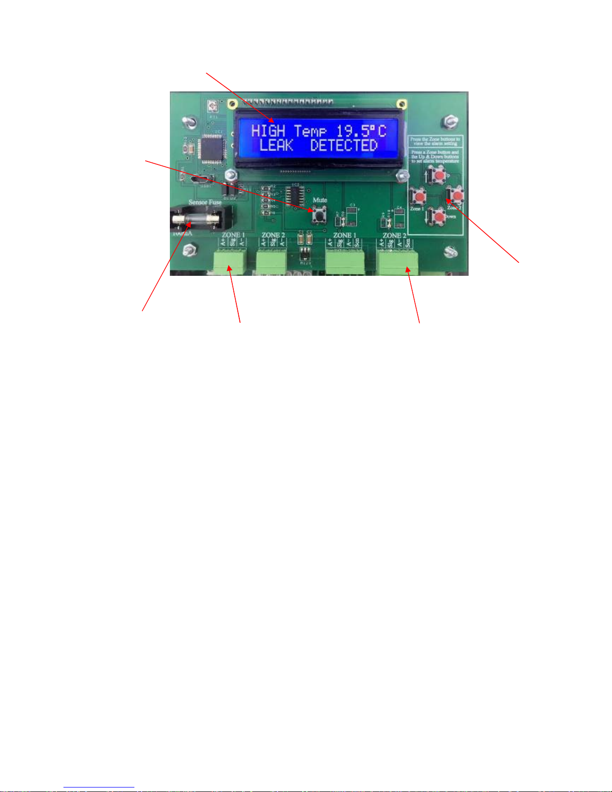
1) Display and Control
2) Operation
In normal operation with no alarms or faults, the audible warning device will be OFF and the display will
be showing screen 2 below. The Temperature alarm trip point (setpoint) can be adjusted using the three
red buttons on the top board, see “Setting the alarm Trip Setpoint”. When the ambient temperature
exceeds the alarm setpoint, the audible warning will start pulsing, the display will show the alarm, see
screen 3, the common alarm BMS contact will operate, and if fitted, zone 2 BMS relay will operate, the
remote beacon/beacon sounder will operate and the SMS will send an Alarm message. The unit will
remain in this mode until the “Mute” button has been pressed when the display will change to show the
status of both temperature and water detection alarms, see screen 5, the audible warning will stop and if
fitted the remote sounder will stop. Once the temperature drops below the setpoint by 2ºC, the system will
automatically reset to normal operation provided the “mute” button has been operated. If the temperature
falls below 0ºC or above 50ºC, the audible warning device will sound, and the display will change to
screen 7. The water detection alarm will operate in the same way as described above but screen 4 will be
displayed when a leak has been detected, again this will stay in this mode until the “Mute” button has
been operated to acknowledge the alarm. If a temperature sensor becomes disconnected or damaged, the
audible warning will sound and the display will show the faulty sensor, see screen 6. Again unit will
remain in this mode until the “Mute” button is pressed. Once the sensor fault has been rectified, the
system will automatically revert to normal running. If the water leak detection sensor becomes
disconnected, the unit will go into “Leak Detected” alarm as described above. If the sensor power fuse
blows or is removed, the audible warning will sound and the display will show screen 8. The unit will
remain in this mode until the “Mute” button is pressed. Once the fuse has been replaced, the system will
automatically revert to normal running provided the “mute” button has been operated.
Water & Temperature
Status Display
Mute Alarm Push
Button
Temperature
Alarm Set Point
Buttons see item
5 below
“ZONE 1”
Removable Terminal
Block for Leak Detection
Sensor
Sensor power
fuse
“ZONE 2”
Removable Terminal
Block for Temperature
Sensor
Page 4

4
3) Display Screens Screen 1
The unit will display this for a few seconds after powering up
Screen 2
The unit has no alarms and is showing the current temperature
Screen 3
High temperature Alarm; this statement will flash until the “Mute” button is pressed
Screen 4
Water leak Alarm; this statement will flash until the “Mute” button is pressed
Screen 5
After “Muting” an alarm the display will show the status and current temperature
Screen 6
The temperature sensor has become disconnected or faulty
Screen 7
The temperature has gone below 0ºC or above 50ºC
Page 5

5
Screen 8
The sensor power fuse has blown
Screen 9
Alarm setpoint adjustment
4) Water detection Sensor wiring (Zone 1)
Using the 3 way terminal block as shown in Item 1 above, connect the sensor to the alarm unit as follows
using a 4 core 0.22mm cable. The sensor cable should not exceed 100m in length, and should not be run
in parallel to, or near, any power cables, bus-bars or any source of electrical or radio interference.
Alarm unit
Terminal
reference
Sensor Cable
colour
A+ Red and Yellow
Sig Blue
A- Black
5) Temperature Sensor wiring (Zone 2)
Using the pluggable 4 way terminal block as shown in Item 1 above, connect the temperature sensor to
the alarm unit as follows using a 4 core 0.22mm screened cable such as RS 8124725. The sensor cable
should not exceed 100m in length, and should not be run in parallel to, or near, any power cables, busbars or any source of electrical or radio interference.
Alarm unit Terminal
reference
Cable colour Sensor terminal
refe
rence
A+
RedA+Sig
White
SigA-
Black
A-Scn
Screen
No connection
Do NOT connect the screen to any terminal or earth at the sensor box end
Page 6

6
6) Setting the alarm trip setpoint
Three buttons have been provided to allow the alarm trip point adjustment between 0 and 50ºC. To set the
desired alarm trip point, first press the “Zone 2” button until the display changes to screen 9, the display
will show the current alarm trip point. Whilst holding down the “zone 2” button, repeatedly press the
“Up” or “Down” buttons until the desired alarm temperature is displayed in the screen. Once the desired
alarm temperature is on display, release both buttons. If required, the new setpoint can be verified by
pressing just the “zone 2” button again. The alarm trip point is held into non-volatile memory, so no
further adjustments will be needed unless a new alarm temperature setpoint is required. Please note; the
unit is factory set to 25ºC
Warning setting the alarm to 0 or 50ºC will setup an alarm but the display will change to screen 7 once
the temperature drops below 0ºC or above 50ºC.
7) Positioning the temperature sensor
Care should be taken when positioning the sensor. Remember, hot air rises and forms hot spots, i.e. a
room left hand corner away from any heat source could be 21ºC, whereas the right-hand corner next to
the heat source could be 25ºC. Also positioning the sensor one metre from the floor when the bulk of the
heat source being at two meters, could lead to damage to sensitive equipment because the sensor is
measuring the lower ground floor temperature. Therefore, it is important to mount the sensor in a
position where the room is likely to get the hottest and at a height to cover the whole equipment i.e. a 2m
high server rack would be best if the sensor were mounted at an approximate height of 2 or 2.5 metres on
a wall or column next to the server racks. If the location and type of heat source are unknown at the time
of installation, try positioning the sensor between 1.8 and 2.5 metres (depending on room height) from the
floor in the centre of the room.
8) Power, BMS, beacon and SMS connections
The Common alarm relay is normally energised, de-energised in alarm or power fault, therefore
both “Common Alarm” contacts are identified correctly when the unit is powered and has no
current alarms.
Output Volt Free contacts for use by a Building Management System.
Function Required Fitted as Standard Relay Output Terminals
Temperature alarm (Zone 1)
No
Z1 Alarm
Leak alarm (Zone
2)NoZ2 Alarm
Over temp, Leak alarm or
power fault contact No. 1
Yes Common Alarm
& power fault
Over temp, Leak alarm or
power fault contact No. 1
Yes Common Alarm
& power fault
BMS relays do not operate for blown fuse or sensor fault
90 to 265VAC
Input power
2 x common alarm and
power fault volt free
BMS contacts
If Fitted
Individual zone
alarm contacts to
BMS
12VDC
output to
Beacon or
Beacon
Sounder
Output to
SMS
Page 7

7
9) Beacon and beacon sounder
If a beacon or beacon sounder is supplied connect to the three terminals identified as “Beacon” as
follows.
9a) Non Mutable Beacon or beacon sounder
If the beacon or the beacon sounder is to be active (On all the time) until the water leak alarm has
cleared, connect as follows
Terminal
reference
Connect Beacon / beacon sounder
terminals to the following terminals
+V
Beacon +V or Strobe /Tone + terminal
BOV
Beacon
-
V or Strobe /Tone
-
terminal
SOV
NO connection to this termina
l
9b) Mutable Beacon or beacon sounder
If the beacon or the beacon sounder is to turn off when the “Mute” push button is pressed connect
as follows.
Terminal
reference
Connect Beacon / beacon sounder
terminals to the following terminals
+V
Beacon +V
or Strobe /Tone + terminal
BOV
NO connection to this terminal
SOV
Beacon
-
V or Strobe /Tone
-
terminal
9c) Mutable sounder Beacon on all the time
If the beacon is to remain alight all the time an alarm is current but the sounder is to be turned off
when the “Mute” push button is pressed connect as follows.
Terminal
reference
Connect Beacon / beacon sounder
terminals to the following terminals
+V
Strobe and Tone + terminal
BOV
Strobe
-
terminal
SOV
Tone
-
terminal
Warning; if the above option “9c” is required, remove the electrical link connected between the second
(Strobe -) & third terminals (Tone -) terminals within the sounder.
10) Fitting an SMS / Email messaging system
If an SMS text messaging or Email messaging unit is supplied connect it as follows to the 3 way terminal
block identified as “SMS”.
Terminal
reference.
Cable wire colours fitted
to the messaging system
Z1
BLUE
COM
BLACK
DC
RED
Page 8

8
11) Commissioning
Having connected the unit as described above, turn on the mains power to the unit. The display should
illuminate displaying screen 1 and after a few seconds display screen 2. To test the temperature alarm,
first note the current temperature, press and keep pressed, the internal red “Zone 2 push button, screen 9
should appear. Keeping the “Zone 2” button pressed, repeatedly push and release the “Down” button until
the temperature on display is below the noted ambient temperature. Now release both push buttons, the
audible warning should start pulsing, screen 3 should appear and flash, the “common alarm” contact
should change state, if fitted, the beacon / beacon sounder should start, the “Zone 2 Alarm” relay should
operate and the SMS messaging system should activate. Pressing the “Mute” button will stop the sounder,
change the display to screen 5 and if fitted and connected as shown in (9c), the sounder in the remote
beacon sounder will stop. Once muted, clear the alarm by pressing the “Zone 2” button only this time
using the “Up” button to set the unit to the desired high temperature set point.
To test the water leak alarm, Use a cup of CLEAN water and immerse a small area (50mm long) of cable
into the water. The audible warning should start pulsing, screen 4 should appear and flash in the display,
the “common alarm” contacts should change state and if fitted, the beacon / beacon sounder should start,
the “Zone 1 Alarm” relay should operate and the SMS messaging system should activate. Pressing the
“Mute” button will stop the sounder, change the display to screen 5 and if fitted and connected as shown
in (9c), the sounder in the remote beacon sounder will stop. Once tested, dry the tested area with clean
paper towel.
12) Fault Diagnoses
Fault Possible Reason
Display is OFF and the unit appears dead 1) No power to the control unit. Test with a meter
2)
The power fuse has blown.
Test the fuse with a meter
Screen 1 remains on display all the time 1) Power down the unit and turn on after 1 minute
2)
System fault.
Return to manufacturer
Sensor fault, Screen 6 1) Check the sensor cable for bad terminations or crossed
wiring.
2) Remove the sensor and using 3 short lengths of cable, reterminate the sensor at the alarm unit to illuminate the field
wiring. If the sensor is found to function correctly, the sensor
cable is either too long, faulty or being subjected to electrical
interference.
3) Crossover the zones to see if the fault transfers to the healthy
zone i.e. fault on zone 1, after crossing over fault on zone 2.
4)
Faulty sensor
Return to manufacturer
Screen 8 appears in the display 1) The internal sensor fuse has blown due to over current.
Remove both 4 way sensor terminal connections and check
the sensor wiring for short circuits. Before re-connecting the
sensors, replace the 100mA fuse, the display should change
and display zone 1 and 2 as faulty (screen 5). If this screen
does not appear, Return unit to manufacturer. If it does
appear, plug each zone sensor back in one at a time noting if
the fuse blows again and on what zone.
Horn not working 1) System fault. Return to manufacture
Page 9

9
13) Installation Drawings
Not all the shown devices may be available on your system
A-
L E
N
Mains
3amp
Supply
N/O
COM
N/C
Z1Alarm
N/O
COM
N/C
Z2Alarm
SOV
BOV
+V
Beacon
Com
Z1
DC
SMS
ZONE1
Voltfree contacts
toaBMSsystem
Beaconor
BeaconSounder
SeeItem 6 inthe
installation
Manual
N/O
COM
N/C
N/O
COM
N/C
A+
Sig
Alarm
SMSText
Messaging
Strobe
Tone
+V
Commonalarm
ZONE2
A-
A+
Sig
Scn
A+
Sig
A-
Temperature
Sensor
 Loading...