

Page 1
DUBAI • HOUSTON • NEWCASTLE • SINGAPORE • SHANGHAI • PUSAN • PERTH
TECHNICAL DATA
CABLE GLAND TYPE : T3CDS / T3CDSPB
INGRESS PROTECTION : IP66, NEMA 4X, DELUGE TO DTS01-01
PROCESS CONTROL SYSTEM : BS EN ISO 9001
: ISO / IEC 80079-34:2011
INSTALLATION INSTRUCTIONS FOR
CMP CABLE GLAND TYPES
HAZARDOUS AREA CLASSIFICATION
ATEX CERTIFICATION No : SIRA 06ATEX1283X & SIRA 06ATEX4328X
ATEX CERTIFICATION CODE : II 2 GD Ex d IIC / Ex e II / Ex nR II / Ex tD A21 IP66
IEC Ex CERTIFICATION No : IEC Ex SIR.07.0005X
IEC Ex CERTIFICATION CODE : Ex d IIC / Ex e II / Ex nR II / Ex tD A21 IP66
CSA CERTIFICATION No : CSA.02.310517X
CSA CERTIFICATION CODE : Class I Div 2 Gp, A, B, C, D; Class II Div 2 Gp E, F, G; Class III
UL CERTIFICATION FILE : E200163, E256367
UL CERTIFICATION CODE : Class I, Zone 1, AEx e II; TYPE 4X, OIL RES II
INSTALLATION INSTRUCTIONS
Installation should only be performed by a competent person using the correct tools. Spanners should be used for tightening. Read all instructions
before beginning installation.
SPECIAL CONDITIONS FOR SAFE USE
1. The glands ranges shall only be used on enclosures where the temperature, at the point of mounting, is in the range -60°C to +130°C.
2. When used with braided cable, the cable glands shall be used for fixed installations only. Cables must be effectively clamped to prevent twisting
and pulling.
3. When used in Group I applications, the equipment must only be mounted where the risk of mechanical impact is low.
ACCESSORIES
The following accessories are available from CMP Products, as optional extras, to assist with fixing, sealing and earthing :-
Locknut | Earth Tag | Serrated Washer | Entry Thread (I.P.) Sealing Washer
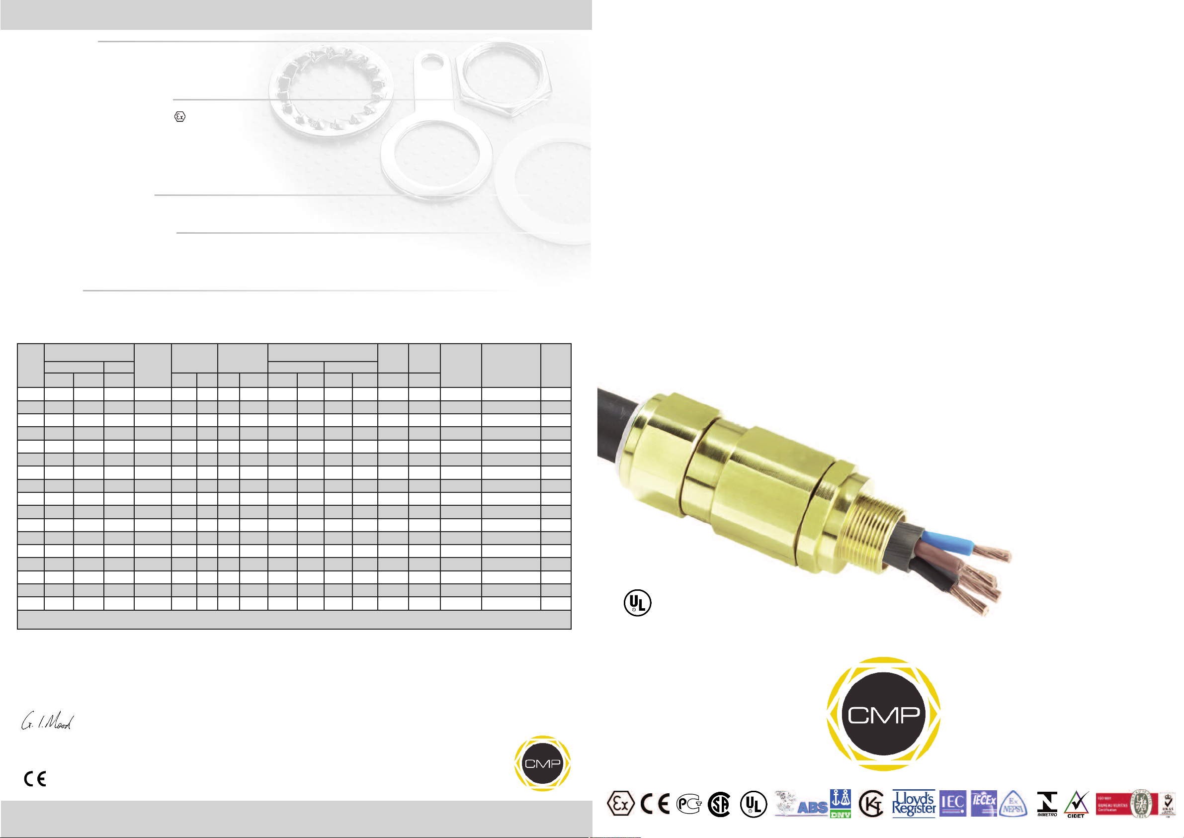
Cable Gland Selection Table
able
Available Entry Threads
Cable
Gland
Size
20S/16 M20 1/2" 3/4" 15.0 3.2 8.7 6.1 13.4 0.15 0.5 0.9 1.0 24.0 25.9 70.0 20S16T3CDS1RA 0.170
20S M20 1/2" 3/4" 15.0 6.1 11.7 9.5 15.9 0.15 0.5 0.9 1.25 24.0 25.9 70.0 20ST3CDS1RA 0.170
20 M20 1/2" 3/4" 15.0 6.5 14.0 12.5 20.9 0.2 0.5 0.9 1.25 30.5 32.9 72.0 20T3CDS1RA 0.256
25S M25 3/4" 1" 15.0 11.1 20.0 14.0 22.0 0.2 0.6 1.25 1.6 37.5 40.5 82.0 25ST3CDS1RA 0.384
25 M25 3/4" 1" 15.0 11.1 20.0 18.2 26.2 0.2 0.6 1.25 1.6 37.5 40.5 82.0 25T3CDS1RA 0.379
32 M32 1" 1 1/4" 15.0 17.0 26.3 23.7 33.9 0.2 0.6 1.6 2.0 46.0 49.7 85.0 32T3CDS1RA 0.560
40 M40 1 1/4" 1 1/2" 15.0 23.5 32.2 27.9 40.4 0.2 0.8 1.6 2.0 55.0 59.4 86.0 40T3CDS1RA 0.848
50S M50 1 1/2" 2" 15.0 31.0 38.2 35.2 46.7 0.2 0.8 2.0 2.5 60.0 64.8 98.0 50ST3CDS1RA 1.055
50 M50 2" 2 1/2" 15.0 35.6 44.1 40.4 53.1 0.3 0.8 2.0 2.5 70.0 75.6 100.0 50T3CDS1RA 1.521
63S M63 2" 2 1/2" 15.0 41.5 50.0 45.6 59.4 0.3 0.8 2.0 2.5 75.0 81.0 108.0 63ST3CDS1RA 1.750
63 M63 2 1/2" 3" 15.0 47.2 56.0 54.6 65.9 0.3 0.8 2.0 2.5 80.0 86.4 103.0 63T3CDS1RA 1.685
75S M75 2 1/2" 3" 15.0 54.0 62.0 59.0 72.1 0.3 0.8 2.0 2.5 89.0 96.1 105.0 75ST3CDS1RA 2.345
75 M75 3" 3 1/2" 15.0 61.1 68.0 66.7 78.5 0.3 0.8 2.0 2.5 99.0 106.9 114.0 75T3CDS1RA 3.200
90 M90 3" 3 1/2" 24.0 66.6 79.3 76.2 90.4 0.4 0.8 3.15 3.15 114.0 123.1 140.0 90T3CDS1RA 5.100
100 M100 4" 4 1/2" 24.0 76.0 91.0 86.1 101.5 0.4 0.8 3.15 4.0 123.0 132.8 170.0 100T3CDS1RA 6.500
115 M115 4 1/2" 5" 24.0 86.0 98.0 101.5 110.3 0.4 0.8 3.15 4.0 133.4 144.1 210.0 115T3CDS1RA 7.000
130 M130 5" 6" 24.0 97.0 115.0 114.2 123.3 0.4 0.8 3.15 4.0 146.1 157.8 250.0 130T3CDS1RA 7.800
** Insert “PB” into the code for T3CDSPB glands e.g. 20T3CDSPB1RA
* For IP67 & IP68 requirements the Overall Cable Diameter (minimum value) shown above should be increased by 1.0 mm to ensure complete compliance
I, The undersigned, hereby declare that the equipment referred to herein conforms to the requirements of the ATEX Directive 94/9/EC and the
following standards:-
Standard Option Grooved Cone Stepped Cone
Metric NPT NPT Min Max Min* Max Min Max Min Max Max Max
hread
T
Length
etric
m
C
Bedding
Diameter
Dimensions are displayed in millimetres unless otherwise stated
Overall Cable
Diameter
Armour Wire Diameter
Across
Flats
Across
Corners
Protrusion
Length
rdering
O
Reference
(Brass Metric)
*
*
able
C
Gland
Weight
Kgs)
(
T3CDS & T3CDSPB
CABLE GLAND FOR USE WITH SINGLE WIRE ARMOUR (SWA), WIRE BRAID, STRIP, AND TAPE ARMOUR
(T3CDSPB VERSION CAN ALSO BE USED ON CABLE WITH A LEAD SHEATH).
FOR USE IN HAZARDOUS LOCATIONS.
INCORPORATING EC DECLARATION OF CONFORMITY TO DIRECTIVE 94/9/EC
M
CMP TRITON
T
CDS
COMPENSATING DISPLACEMENT SEAL SYSTEM.
CABLE GLAND TYPES
CABLE GLAND TYPES
T3CDS & T3CDSPB
T3CDS & T3CDSPB
LISTED MARINE SHIPBOARD
CABLE FITTING
31YM
29NX
M
T
DELUGE PROOF CABLE GLAND FEATURING
CMP Document No. FI408 Issue 7 01/13
EN60079-0:2006, EN60079-1:2007, EN60079-7:2007, EN60079-15:2005, BS 6121:1989, EN50262:1989 (Amd 2001), EN61241-0:2004,
EN61241-1:2004
Dr Geof Mood - Technical Director - (Authorised Person)
Glasshouse Street • St. Peters • Newcastle upon Tyne • NE6 1BS
Tel: +44 191 265 7411 • Fax: +44 191 265 0581
0518
Notified Body: Sira Certification Service, Rake Lane, Chester CH4 9JN, England.
E-Mail: cmp@cmp-products.co.uk • Web: www.cmp-products.com
www.cmp-products.com
Logo’s shown for illustration purposes only. Please check certification for details
Page 2
DUBAI • HOUSTON • NEWCASTLE • SINGAPORE • SHANGHAI • PUSAN • PERTH
www.cmp-products.com
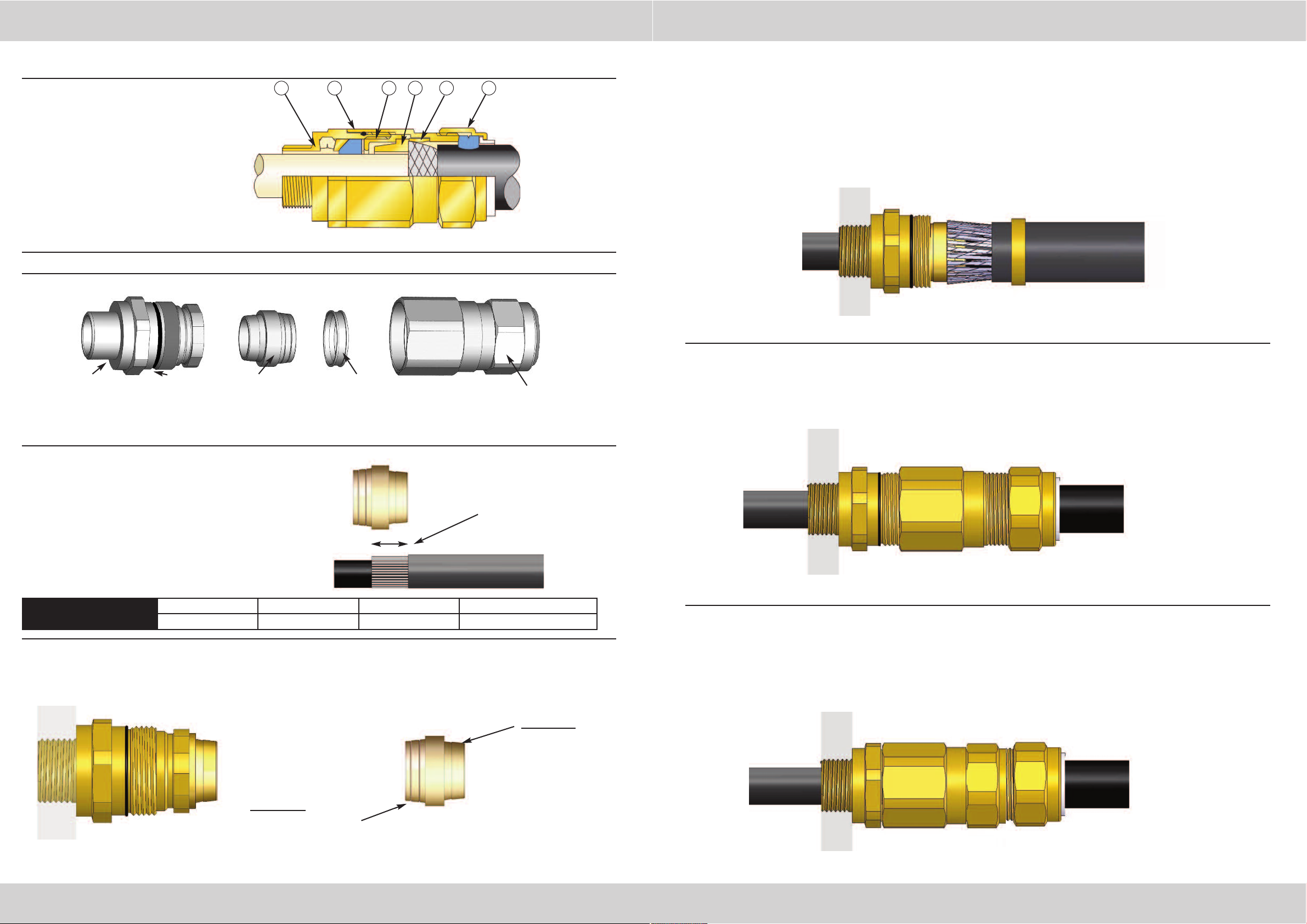
INSTALLATION INSTRUCTIONS FOR CMP CABLE GLAND T3CDS & T3CDSPB
CABLE GLAND COMPONENTS
1. Entry Item
2. Body
3. Compensating Sleeve
4. Reversible Armour Cone
5. AnyWay Clamping Ring
6. Outer Seal Nut
4321
PLEASE READ ALL INSTRUCTIONS CAREFULLY BEFORE BEGINNING THE INSTALLATION
SUB-ASSEMBLY A
“CDS” INNER SEAL
HOUSING
DELUGE
SEAL
ITEM 4 ITEM 5 SUB-ASSEMBLY B
REVERSIBLE
ARMOUR CONE
ANYWAY
CLAMPING RING
BODY AND OUTER
SEAL NUT
65
4. Pass the cable through sub-assembly A, spacing the armour or braid evenly around the cone.
Whilst continuing to push the cable forward to keep the cable braid or armour in contact with the
cone, tighten the compensating sleeve (3) into the entry component (1) until all the threads are
used. (Note that the internal compensator will prevent the cable gland inner seal from being overtightened onto the cable inner sheath.)
The inner sheath of the T3CDSPB gland contains a device to automatically make an electrical
contact with the lead sheath on the cable as the cable is installed.
5. Terminate the cable by tightening the body (2) onto the entry component (1) using a spanner on
each part. Tighten the body until the body and entry components are metal to metal and cannot
be tightened further.
1. Separate the gland into two sub-assemblies, A and B, by unscrewing the body (2) from the entry
item (1). Note that items (4) and (5) are loose items.
2. Prepare the cable by stripping back the
cable outer sheath and armour to suit the
equipment geometry. Expose the armour
by stripping back the outer sheath further
Cable Strip
Length “L”
using the table below as a guide.
CABLE GLAND SIZE 20S/16, 20S, 20 25S, 25, 32, 40 50S, 50, 63S, 63 75S, 75, 90, 100, 115, 130
CABLE STRIP LENGTH “L” 12mm 15mm 18mm 20mm
3. Secure the entry components (sub-assembly A) into the equipment. (Not for remote installation)
Pass the sub-assembly B (outer seal first) and AnyWay clamping ring (5) over the cable.
Insert the reversible armour cone (4) in the sub-assembly A, orientation to suit cable (see below)
Stepped side of
cone outwards -
to terminate SWA
cable.
6. Tighten the outer seal nut (6) until it comes to an effective stop. This will occur when:A) The outer seal nut (6) has clearly engaged the cable and cannot be further tightened
without the use of excessive force by the installer.
B) The outer seal nut (6) is metal to metal with the body of the gland (2).
Grooved side of
cone outwards -
to terminate braid,
strip armour, pliable
wire or tape armour.
www.cmp-products.com
DUBAI • HOUSTON • NEWCASTLE • SINGAPORE • SHANGHAI • PUSAN • PERTH
 Loading...