

CMP PX780REXDM4M4, PX780REXDM2M2, PX780REXDM6M6, PX780REXDM7M7, PX780REXDM8M8 Installation Instructions Manual
...Page 1
TECHNICAL DATA
PRODUCT TYPE : PX780REX
INGRESS PROTECTION : IP66 when used with CMP sealing accessories
PROCESS CONTROL SYSTEM : ISO 9001
: ISO/IEC 80079-34:2011
EXPLOSIVE ATMOSPHERES CLASSIFICATION
ATEX CERTIFICATION No : CML 18ATEX1327X
ATEX CERTIFICATION CODE : ^II 2G 1D Ex db IIC Gb, Ex eb IIC Gb, Ex ta IIIC Da IP6X
: ^IM2 Ex db I Mb / Ex eb I Mb
IECEx CERTIFICATION No : IECEx CML 18.0190X
IECEx CERTIFICATION CODE : Ex db IIC Gb, Ex eb IIC Gb, Ex db I Mb, Ex eb I Mb, Ex ta IIIC Da IP6X
cCSAus CERTIFICATION No : 1055233
CODE OF PROTECTION : Class I, Div 1 and 2, Groups A,B,C and D; Enclosure Type 4X: Class I Zone 1, AEx de II; Ex de II
INMETRO CERTIFICATION No : TÜV 18.2088X
INMETRO CERTIFICATION CODE : Ex db IIC Gb, Ex eb IIC Gb, Ex db I Mb, Ex eb I Mb, Ex ta IIIC Da IP6X
INSTALLATION INSTRUCTIONS
1. Installation should only be performed by a competent person using the correct tools. Spanners should be used for tightening. Read all instructions before beginning installation.
2. The interface between a cable entry device and its associated enclosure / cable entry will require additional sealing to achieve ingress protection (IP) ratings higher than IP54. The
minimum protection level is IP54 for explosive gas atmospheres and IP6X for explosive dust atmospheres. Parallel threads (and tapered threads when using a non-threaded entry)
require a CMP sealing washer or integral O-ring face seal (where available) to maintain IP66, 67 and 68 (when applicable). It is the installer’s responsibility to ensure the IP rating
is maintained at the interface.
Note: When fitted to a threaded entry, all tapered threads will automatically provide an ingress protection rating of IP68.
3. A CMP earth tag should be used when it is necessary to provide an earth bond connection. CMP earth tags have been independently tested to comply with Category B rating
specified in IEC 62444 (there are no ratings stated in IEC 60079-0). Ratings are shown in the associated table. CMP earth tags slip over the cable gland or accessory entry thread
from inside/outside the enclosure and must be secured with a locknut (if fitted internally).
CMP Ear th Tag Size
20 3.06
25 4.06
32 5.40
40 7.20
50 10.40
63 10.40
75 10.40
SPECIFIC CONDITIONS OF USE
Only one union is to be used with any single cable entry on the associated equipment.
ACCESSORIES
The following accessories are available from CMP Products, as optional extras, to assist with fixing, sealing and earthing :Locknut | Earth Tag | Serrated Washer | Entry Thread (I.P.) Sealing Washer
CMP Products Limited on its sole responsibility declares that the equipment referred to herein conforms to the requirements of the ATEX Directive 2014/34/EU and the following standards:
EN 60079-0:2018, EN 60079-1:2014, EN 60079-7:2015, EN 60079-31:2014
David Willcock – Certification Engineer (Authorised Person)
CMP Products Limited, Cramlington, NE23 1WH, UK
15 April 2019
Short Circuit Ratings Symmetrical Fault Current
(kA) fo r 1 second
2776
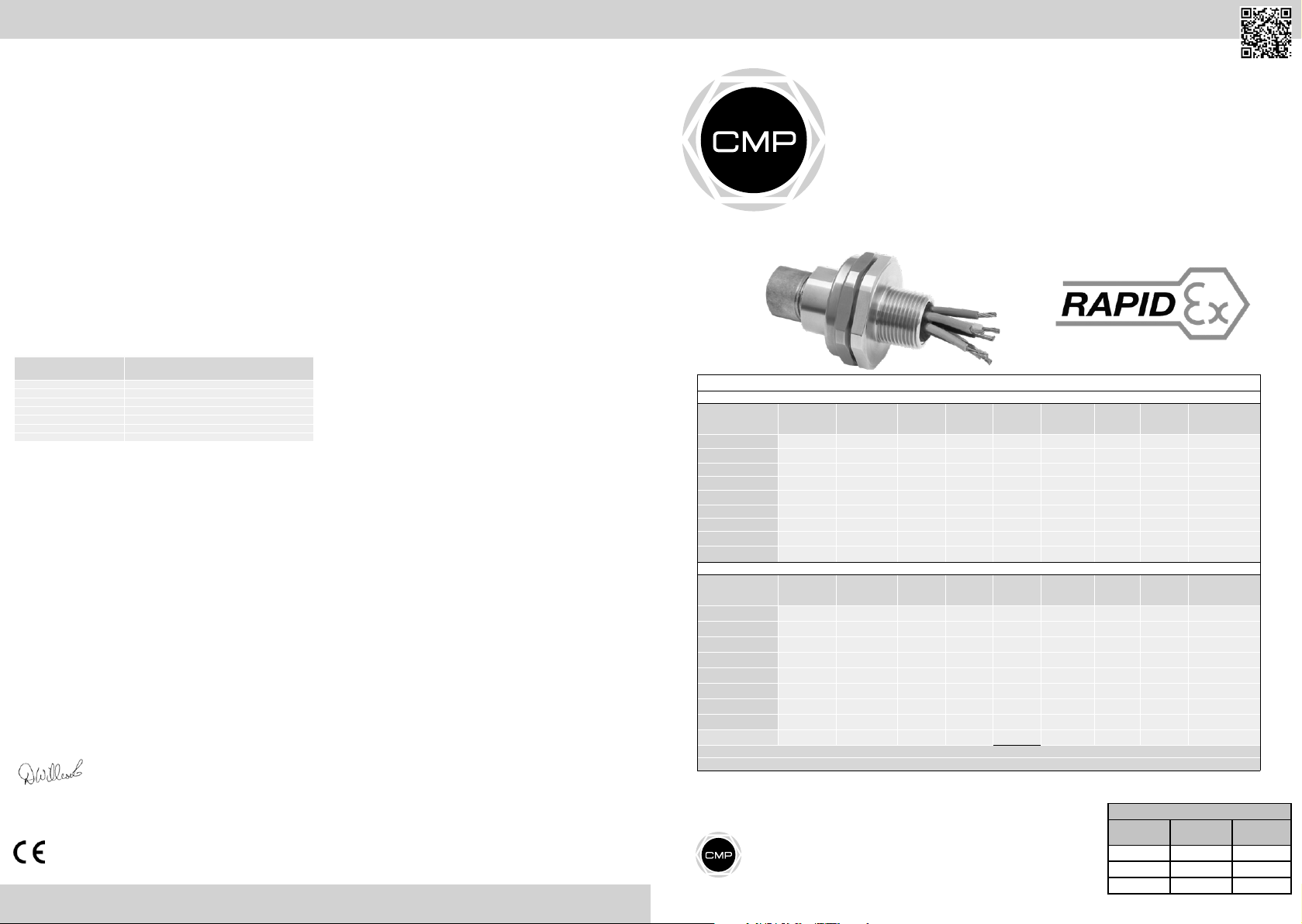
SCAN FOR INSTALLATION VIDEOS
INSTALLATION INSTRUCTIONS
FOR UNION TYPE PX780REX
UNION TYPE PX780REX FOR CONNECTING CONDUITS TO ENCLOSURES OR
CONDUITS TO EACH OTHER USING RAPIDEX RESIN IN EXPLOSIVE ATMOSPHERES.
INCORPORATING EU DECLARATION OF CONFORMITY TO DIRECTIVE [2014/34/EU]
Product Selection Table
Ordering Reference
(Brass, Metric)
PX780REXD M2M2
PX780REXDM3M3
PX780REXDM4M4
PX780REXD M5M5
PX780REXDM6M6
PX780REXD M7M7
PX780REXDM8M8
PX780REXDM9M9
PX780REXDM10M10
Ordering Reference
(Brass, NPT)
PX780 REXDT1T1 1/2” 0.79 1/2”
PX780REXDT2T2 3/4” 0.80 3/4”
PX780REXDT3T3 1” 0.98 1”
PX78 0REX DT4T4 1-1/4 ” 1.01 1-1/4”
PX780REXDT5T5 1-1 /2” 1.0 3 1-1/ 2”
PX780REXDT6 T6 2” 1. 06 2”
PX780REXDT7T7 2-1 /2” 1.5 7 2-1/ 2”
PX780REXDT8T8 3” 1.63 3”
PX780REXDT9T9
For material o ptions please add the follo wing suffix to the Orde ring Reference; Brass (no s uffix required), Ni ckel Plated Brass “5”, 316 Grade Stainles s Steel “4”, Copper Free Alumin ium “1”
Alternate thread types available
Can be supplied with mixed thread types e.g. PX780REX DM10T10 - M100 male thread, 4”NPT female thread, please contact CMP for more information
Male For ward
Thread S ize
M20 X 1.5 15.0 M20 X 1.5
M25 X 1.5 15. 0 M25 X 1.5
M32 X 1.5 15. 0 M32 X 1.5
M40 X 1.5 15 .0 M4 0 X 1.5
M50 X 1.5 15. 0 M50 X 1.5
M63 X 1.5 15 .0 M6 3 X 1.5
M75 X 1.5 15. 0 M75 X 1.5
M90 X 2.0 24. 0 M90 X 2.0
M100 x 2.0 24.0 M100 x 2 .0
Male For ward
Thread S ize
3-1/ 2” 1.69 3-1/2 ”
Glasshouse Street • St. Peters • Newcastle upon Tyne • NE6 1BS
Tel: +44 191 265 7411 • Fax: +44 191 715 464
E-Mail: customerservices@cmp-products.co.uk • Web: www.cmp-products.com
Minimum
Thread Length
Minimum
Thread Length
Female Re ar
Thread S ize
Female Re ar
Thread S ize
All dimensio ns shown are in millimetres u nless otherwise state d
www.cmp-products.com
METRIC
Diamet er
Over Cores
Diamet er
Over Cores
Max.
Numbe r of
12.6 21 3 6.1 46.0 50.3
17.5 30 36 .1 50.0 54.7
23.6 50 35.2 6 0.0 65.7
30.0 59 35 .2 65.0 71.2
41.0 115 35.3 75.0 82. 2
53.7 115 35. 3 90.0 98.7
64.2 140 38.8 100.0 109.7
75.3 140 45.0 120 .0 131.7
83.6 200 83.9 145. 0 159.2
NPT
Numbe r of
12.6
17.5
23.6
30.0
36.6
47.9
59.9
75.3
83.6
Protrusion
Cores
Max.
Cores
Length
Protrusion
Length
21 35.4 46.0 50.3
30 35.0 50.0 5 4.7
50 33.7 60.0 65.7
59 37. 0 65.0 71.2
115 38.2 75.0 82.2
115 3 9.1 90.0 98.7
140 5 4.1 10 0.0 109.7
140 52.5 120. 0 131.7
200 80.0 145.0 159.2
Across
Flats Hex
Across
Flats Hex
Certicate Revision Date
IFS 9 05/19
ATEX / IECEx 6 04/19
cCSAus 5 05/16
Across
Corners Ø
‘D’
Across
Corners Ø
‘D’
FI471
Installation
Torque (Nm)
7
10
15
25
30
45
45
45
45
Installation
Torque (Nm)
7
10
15
25
30
45
45
45
45
Page 2
INSTALLATION INSTRUCTIONS FOR CMP CABLE UNION PX780REX
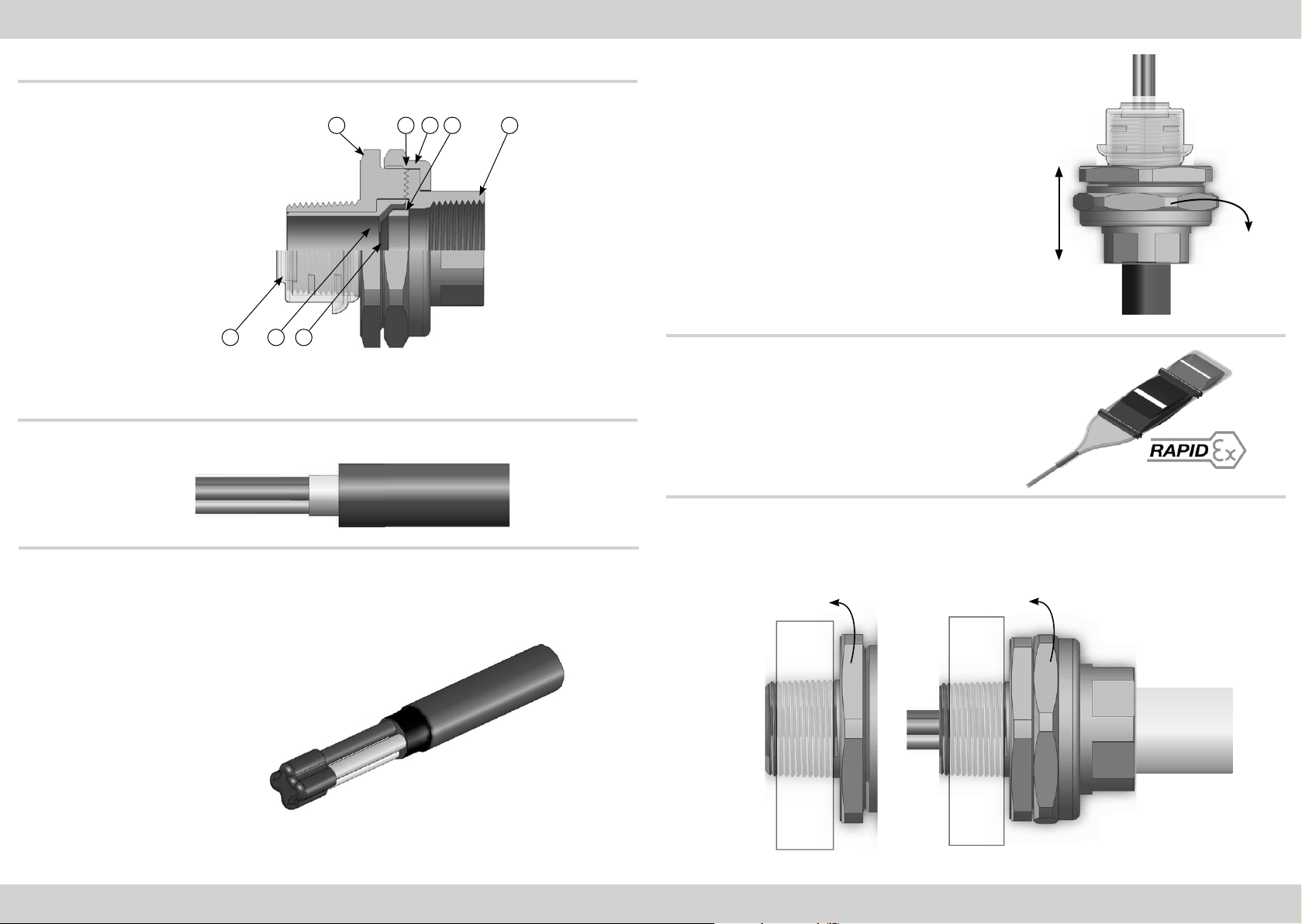
UNION COMPONENTS - It is not necessary to dismantle the union any further than illustrated below
1 2 3 4
1. Entry Item
2. Serrated Flamepath
3. Nut
4. Conduit Connector
5. Washer
6. Resin Dam
7. Compound Tube
8. Thread Shield
678
NOTE: THERE IS NO NEED TO DISSASSEMBLE THE UNION
PLEASE READ ALL INSTRUCTIONS CAREFULLY BEFORE BEGINNING THE INSTALLATION
1. Prepare the cable by removing the outer sheath from the cores so that they are exposed within
the Compound Tube when finally assembled.
5
3. Feed the cables/cores through the union.
If the installation uses only cores (i.e. no cable sheath) then
electrical tape must be wrapped around the cores at the position
at which it will engage the resin dam.
Use the length of the union as a guide to position the tape as
shown above (guide length “L”)
L
4. Mix the Resin and apply as per RapidEx instructions.
2. Remove any bedding or fillers from around the cable cores. If the cable cores have screens,
these should be unwound and then twisted together to form a single core.
This single core and/or any drain wires present should be sleeved with some heat shrink tubing.
Electrical tape MUST be wrapped around the tips of the
cable cores. This is to ensure the cable cores are
together and also to cover any sharp edges that could
potentially tear the Resin Dam during installation.
5.1 When the Resin has cured the Entry Item (1) should be removed from the assembly and fully tightened into the
apparatus.
5.2 Tighten the Conduit Connector (4) onto the conduit and then tighten to the Entry Item (1) using the Nut (3) to
complete the installation.
www.cmp-products.comwww.cmp-products.com
 Loading...