

Page 1

DUBAI • HOUSTON • NEWCASTLE • SINGAPORE • SHANGHAI • PUSAN • PERTH
TECHNICAL DATA
CABLE GLAND TYPE : A2FFC
INGRESS PROTECTION : IP66, NEMA 4X
PROCESS CONTROL SYSTEM : BS EN ISO 9001
ISO/IEC 80079-34:2011
INSTALLATION INSTRUCTIONS FOR
A2FFC CONDUIT GLAND
HAZARDOUS AREA CLASSIFICATION
ATEX CERTIFICATION No : SIRA06ATEX1097X, SIRA07ATEX4326X
ATEX CERTIFICATION CODE : II 2/3 GD Ex d IIC, Ex e II, Ex nR II, Ex tD A21 IP66 - Equipment Zone 1, 2, 21 & 22,
IEC Ex CERTIFICATION No : IEC Ex SIR.06.0040X
IEC Ex CERTIFICATION CODE : Ex d IIC / Ex e II / Ex nR II, Ex tD A21 IP66
CSA CERTIFICATION No : 1211841
CSA CERTIFICATION CODE : Ex d IIC / Ex e II, Enclosure Type 4x
INSTALLATION INSTRUCTIONS
Installation should only be performed by a competent person using the correct tools. Spanners should be used for tightening. Read all instructions
before beginning installation.
SPECIAL CONDITIONS FOR SAFE USE
• The A2FFC shall only be used where the temperature, at the point of entry, is between -60°C and +130°C.
• The entry component threads may need additional sealing to maintain the ingress protection rating as applicable to the associated equipment to
which it will be attached.
• The A2FFC is only suitable for flexible conduit installations. Cables must be effectively clamped to prevent pulling or twisting.
able
C
Connector
Size
20S16 M20 X 1.5 15.0 29.0 17.0 3.2 4.3 5.1 9.8 20S16A2FFC1RAC000 0.044
20S16 M20 X 1.5 15.0 29.0 17.0 3.2 5.8 6.8 9.0 20S16A2FFC1RA001 0.048
20S16 M20 X 1.5 15.0 29.0 17.0 3.2 6.6 7.8 11.6 20S16A2FFC1RAC004 0.05
20S16 M20 X 1.5 15.0 29.0 17.0 3.2 8.0 9.1 13.9 20S16A2FFC1RAC009 0.05
20S16 M20 X 1.5 15.0 29.0 17.0 3.2 8.1 9.5 13.0 20S16A2FFC1RAC010 0.05
20S16 M20 X 1.5 15.0 29.0 17.0 3.2 8.1 10.2 14.0 20S16A2FFC1RAC020 0.054
20S16 M20 X 1.5 15.0 29.0 17.0 3.2 8.1 10.9 15.9 20S16A2FFC1RAC025 0.054
20S16 M20 X 1.5 15.0 29.0 17.0 3.2 8.1 11.7 15.9 20S16A2FFC1RAC030 0.056
20S M20 X 1.5 15.0 29.0 17.0 6.1 9.9 10.9 15.9 20SA2FFC1RAC025 0.057
20S M20 X 1.5 15.0 29.0 17.0 6.1 11.7 13.0 16.0 20SA2FFC1RAC040 0.057
20S M20 X 1.5 15.0 29.0 17.0 6.1 11.7 13.9 18.9 20SA2FFC1RAC045 0.059
20S M20 X 1.5 15.0 29.0 17.0 6.1 11.7 14.7 18.7 20SA2FFC1RAC060 0.061
20 M20 X 1.5 15.0 34.0 21.0 6.5 14.0 13.0 16.0 20A2FFC1RAC040 0.057
20 M20 X 1.5 15.0 34.0 21.0 6.5 13.1 15.6 21.0 20A2FFC1RAC050 0.082
20 M20 X 1.5 15.0 34.0 21.0 6.5 14.0 16.9 20.5 20A2FFC1RAC066 0.086
20 M20 X 1.5 15.0 34.0 21.0 6.5 14.0 18.0 21.0 20A2FFC1RAC070 0.09
20 M20 X 1.5 15.0 34.0 21.0 6.5 14.0 18.7 24.0 20A2FFC1RAC075 0.09
20 M20 X 1.5 15.0 34.0 21.0 6.5 14.0 20.0 23.5 20A2FFC1RAC080 0.095
20 M20 X 1.5 15.0 34.0 51.0 6.5 14.0 20.5 27.0 20A2FFC1RAC085 0.095
25 M25 X 1.5 15.0 44.0 25.0 11.1 15.3 17.6 25.0 25A2FFC1RAC100 0.115
25 M25 X 1.5 15.0 44.0 25.0 11.1 18.7 20.7 26.0 25A2FFC1RAC105 0.115
25 M25 X 1.5 15.0 44.0 25.0 11.1 20.0 22.3 26.5 25A2FFC1AC110 0.115
25 M25 X 1.5 15.0 44.0 25.0 11.1 20.0 23.7 30.8 25A2FFC1RAC115 0.124
25 M25 X 1.5 15.0 44.0 25.0 11.1 20.0 25.1 29.0 25A2FFC1RAC120 0.124
25 M25 X 1.5 15.0 44.0 25.0 11.1 20.0 26.5 34.0 25A2FFC1RAC180 0.124
32 M32 X 1.5 15.0 45.5 29.0 17.0 26.0 28.1 32.0 32A2FFC1RAC250 0.182
32 M32 X 1.5 15.0 45.5 29.0 17.0 26.3 30.4 38.0 32A2FFC1RAC280 0.188
32 M32 X 1.5 15.0 45.5 29.0 17.0 26.3 35.0 43.0 32A2FFC1RAC290 0.188
40 M40 X 1.5 15.0 50.0 30.0 23.5 32.2 36.4 44.0 40A2FFC1RAC300 0.23
40 M40 X 1.5 15.0 50.0 30.0 23.5 32.2 40.0 48.0 40A2FFC1RAC380 0.23
50S M50 X 1.5 15.0 50.0 30.0 31.0 38.2 46.5 58.7 50SA2FFC1RAC450 0.3
50S M50 X 1.5 15.0 50.0 30.0 31.0 38.2 51.2 60.0 50SA2FFC1RAC500 0.3
50 M50 X 1.5 15.0 50.0 30.0 35.6 44.1 51.2 60.0 50A2FFC1RAC550 0.34
I, the undersigned, hereby declare that the equipment referred to herein conforms to the requirements of the ATEX Directive 94/9/EC and the following standards:-
EN 60079-0:2006, EN 60079-1:2007, EN 60079-7:2007, EN 60079-15:2005, BS 6121:1989, EN 50262:1998 (Amd 2001), EN 61241-0:2004, EN 61241-1:2004.
Entry
hread
T
“C”
Metric ID OD ID OD
Min Entry
Thread
ength “E”
L
Gas Groups IIA, IIB & IIC
ax
M
Envelope
Diameter
“
Protrusion
ength
L
D”
“F”
All dimensions in millimeters
Diameter Of Cable
A”
“
Typical Diameter Of
rmour Conduit
A
B”
“
Ordering
eference
R
(Brass Metric)
Cable
Connector
Weight
Kgs)
(
CONDUIT GLAND FOR USE WITH UNARMOURED AND BRAID ARMOURED CABLES
INCORPORATING EC DECLARATION OF CONFORMITY TO DIRECTIVE 94/9/EC
CONDUIT
CONDUIT
GLAND
GLAND
TYPE
TYPE
A2FFC
A2FFC
Cable Connector Selection Table
CMP Document No. FI412 Issue 6 1012
Dr Geof Mood - Technical Director - (Authorised Person)
Registered Office: Glasshouse Street • St. Peters • Newcastle upon Tyne • NE6 1BS
0518
Notified Body: Sira Certification Service, Rake Lane, Chester CH4 9JN, England.
E-Mail: cmp@cmp-products.co.uk • Web: www.cmp-products.com
www.cmp-products.com
Tel: +44 191 265 7411 • Fax: +44 191 265 0581
Logo’s shown for illustration purposes only. Please check certification for details
Page 2
DUBAI • HOUSTON • NEWCASTLE • SINGAPORE • SHANGHAI • PUSAN • PERTH
INSTALLATION INSTRUCTIONS FOR CMP CONDUIT GLAND TYPE A2F-FC
www.cmp-products.com
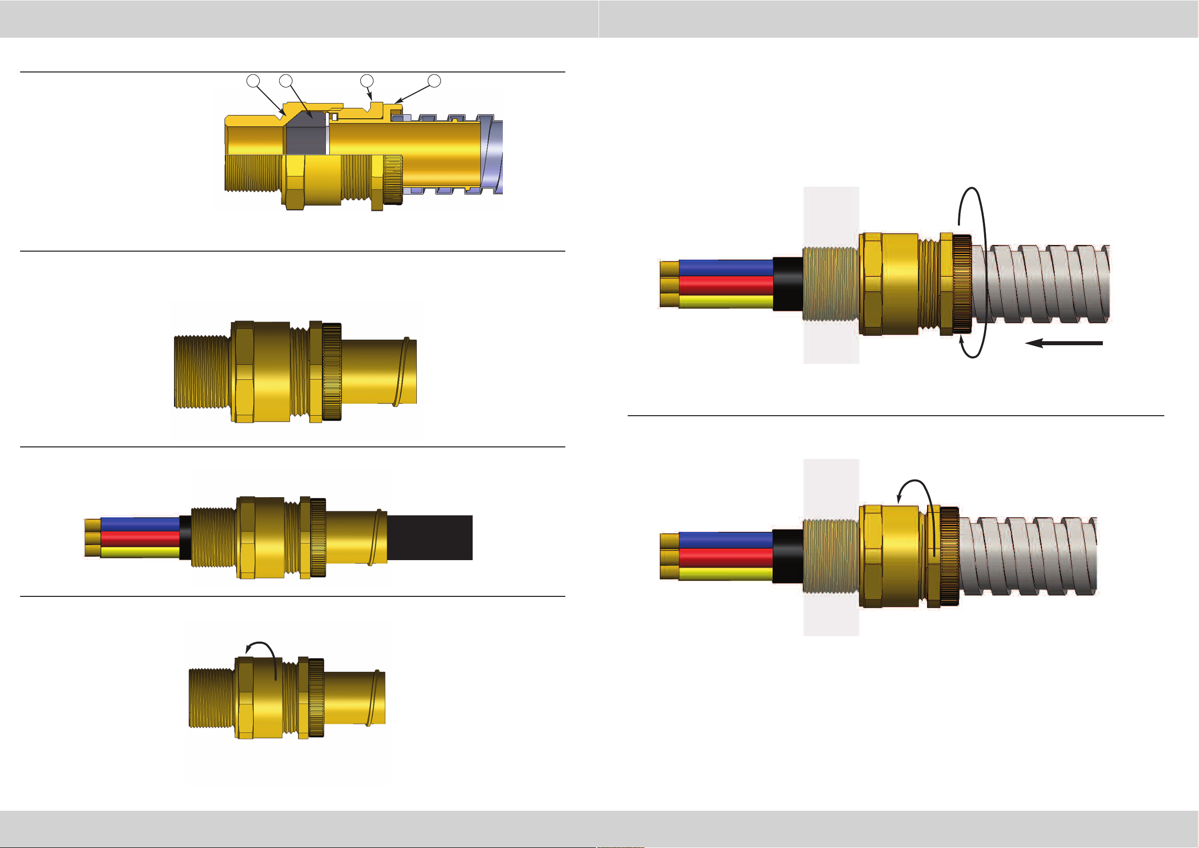
CONDUIT GLAND COMPONENTS
1. Entry Item
2. Seal
3. Seal Nut
4. Conduit Anchor
PLEASE READ ALL INSTRUCTIONS CAREFULLY BEFORE BEGINNING THE INSTALLATION
4321
There is no need to disassemble the gland in order to fit it to the conduit.
1. Slacken the seal nut (3) to relax the seal.
4. Bring the conduit into engagement with the conduit anchor (4) and then screw the anchor into
the conduit until it is fully engaged
2. Pass enough cable through the seal (2) to suit the installation.
3. Fit the gland into the equipment and fully tighten the entry item (1).
5. Tighten the seal nut (3) by hand until resistance is felt (when the seal engages the cable) and
then tighten further one full turn with a spanner.
www.cmp-products.com
DUBAI • HOUSTON • NEWCASTLE • SINGAPORE • SHANGHAI • PUSAN • PERTH
 Loading...