

Page 1
All content © 2018, cmotion GmbH. All specications are subject to change without further notice.
http://www.cmotion.eu
page 1 of 80
v1.1 | November, 2018
Software Release Package v1.1
cPRO hand unit
User Guide
Page 2

All content © 2018, cmotion GmbH. All specications are subject to change without further notice.
http://www.cmotion.eu
page 2 of 80
Imprint
Copyright
Copyright © 2018 cmotion GmbH (cmotion).
All rights reserved. No portions of this document may be reproduced without prior written
consent of cmotion GmbH.
Specications are subject to change without notice. Errors, ommissions, and
modications excepted.
For further assistance
cmotion GmbH
Wiedner Hauptstraße 135/B3
1050 Wien
Fbnr.: FN220240H – HG Wien
UID-Nr.: ATU 54026806
http://www.cmotion.eu
[email protected]
+43 1 7891096
This USER GUIDE applies to the following product:
K2.0016602 cPRO hand unit with Software Release Package v1.1
Document revision history: v1.1
Release Date: 15.11.2018
Page 3

All content © 2018, cmotion GmbH. All specications are subject to change without further notice.
http://www.cmotion.eu
page 3 of 80
Disclaimer
Before using the products described in this manual, be sure to read and understand all
the respective instructions.
The cmotion Software Release Package v1.1 cPRO hand unit is only available to
commercial customers. By utilization, the customer agrees that the cPRO hand unit or
other components of the system are deployed for commercial use only. Otherwise the
customer must contact cmotion before utilization.
While cmotion endeavors to enhance the quality, reliability and safety of their products,
customers agree and acknowledge that the possibility of defects thereof cannot be
eliminated entirely.
To minimize the risk of damage to property or injury (including death) to persons arising
from defects in the products, customers must incorporate sucient safety measures in
their work with the system and heed the stated canonic use.
cmotion or its subsidiaries do not assume any responsibility for losses incurred due to
improper handling or conguration of the cPRO hand unit or other system components.
cmotion assumes no responsibility for any errors that may appear in this document. The
information is subject to change without notice.
For product specication changes after this manual was published, refer to the
latest published cmotion data sheets or release notes, etc., for the most up-to-date
specications. Not all products and/or types are available in every country. Please check
with your cmotion sales representative for availability and additional information.
Neither cmotion nor its subsidiaries assume any liability for infringement of patents,
copyrights or other intellectual property rights of third parties by or arising from the
use of cmotion products or any other liability arising from the use of such products. No
license, express, implied or otherwise, is granted under any patents, copyrights or other
intellectual property right of cmotion or others.
cmotion or its subsidiaries expressly exclude any liability, warranty, demand or other
obligation for any claim, representation, cause, action, or whatsoever, express or implied,
whether in contract or not, including negligence, or incorporated in terms and conditions,
whether by statue, law or otherwise. In no event shall cmotion or its subsidiaries be
liable for or have a remedy for recovery of any special, direct, indirect, incidental, or
consequential damages, including, but not limited to lost prots, lost savings, lost
revenues or economic loss of any kind or for any claim by a third party, downtime, goodwill, damage to or replacement of equipment or property, any cost or recovery of any
material or goods associated with the assembly or use of our products, or any other
damages or injury of the persons and so on or under any other legal theory.
In the event that one or all of the foregoing clauses are not allowed by applicable law, the
fullest extent permissible clauses by applicable law are validated
Page 4

All content © 2018, cmotion GmbH. All specications are subject to change without further notice.
http://www.cmotion.eu
page 4 of 80
Table of Contents
1. For your safety ............................................................................................................ 8
2. Audience and intended use ...................................................................................... 10
3. Scope of delivery and warranty ................................................................................ 10
4. Introduction .............................................................................................................. 11
4.1. LBUS connector ................................................................................................. 12
4.2. CAM interface ..................................................................................................... 12
5. cPRO hand unit hardware layout .............................................................................. 13
5.1. Hardware layout overview .................................................................................. 13
5.2. Control interface ................................................................................................. 14
5.2.1. Knob ............................................................................................................ 14
5.2.1.1. Mechanical hard stops .................................................................... 14
5.2.1.2. Panic button .................................................................................... 15
5.2.1.3. Pre-marked focus rings ................................................................... 15
5.2.1.4. Datum line ........................................................................................ 15
5.2.1.5. Knob illumination and status LEDs .................................................. 15
5.2.2. Slider ........................................................................................................... 16
5.2.2.1. Pre-marked iris strips ....................................................................... 16
5.2.2.2. Slider illumination and status LEDs ................................................. 16
5.2.3. Joystick ....................................................................................................... 17
5.2.3.1. Position indicator display ................................................................. 17
5.2.3.2. Joystick status LED ......................................................................... 17
5.2.4. Thumb wheel ............................................................................................... 18
5.2.5. Buttons / camera status LED ...................................................................... 18
5.2.5.1. REC button and camera status LED ................................................ 19
5.2.5.2. User buttons .................................................................................... 19
5.2.5.3. Back button ..................................................................................... 20
5.2.5.4. Menu buttons ................................................................................... 20
5.2.5.4.1. MB2 (QUICK NAV) .................................................................. 20
5.2.5.4.2. Quick navigation between main screens ................................21
5.2.5.4.3. Quick navigation main screens to adjustment menu .............21
5.2.5.5. HOME button ................................................................................... 21
5.2.5.6. System status LED .......................................................................... 21
5.2.6. Touch screen ............................................................................................... 22
Page 5

All content © 2018, cmotion GmbH. All specications are subject to change without further notice.
http://www.cmotion.eu
page 5 of 80
6. cPRO hand unit software layout ............................................................................... 23
6.1. GUI main screen overview.................................................................................. 23
6.1.1. MAIN screen ................................................................................................ 25
6.1.2. FIZ main screen ........................................................................................... 25
6.1.2.1. Focus main screen ........................................................................... 26
6.1.2.2. Iris main screen ................................................................................ 26
6.1.2.3. Zoom main screen ........................................................................... 27
6.1.2.4. Lens information main screen .......................................................... 27
6.1.3. Camera main screen ................................................................................... 27
6.1.4. Rangender main screens ........................................................................... 28
6.1.4.1. Rangender overview screen .......................................................... 28
6.1.4.2. Rangender settings screen ............................................................ 29
6.1.5. Buttons main screens .................................................................................. 29
6.1.6. Controls main screen .................................................................................. 30
6.1.7. Motors main screens ................................................................................... 31
6.2. Adjustment menu ............................................................................................... 32
6.2.1. Adjustment menu overview ......................................................................... 32
6.2.2. Adjustment menu navigation ....................................................................... 33
6.2.3. Menu ........................................................................................................... 33
6.2.3.1. MAIN ................................................................................................ 34
6.2.3.1.1. Radio ......................................................................................34
6.2.3.1.1.1. RF .........................................................................34
6.2.3.1.1.2. Channel ................................................................34
6.2.3.1.1.3. Region ..................................................................34
6.2.3.1.2. Unit .........................................................................................35
6.2.3.1.3. Brightness ...............................................................................36
6.2.3.1.3.1. Auto activate.........................................................36
6.2.3.1.3.2. Auto brightness ....................................................36
6.2.3.1.3.3. Display ..................................................................36
6.2.3.1.3.4. Keypad brightness ...............................................36
6.2.3.1.3.5. Knob brightness ...................................................36
6.2.3.1.3.6. Slider brightness ...................................................37
6.2.3.1.3.7. Joystick brightness...............................................37
6.2.3.1.4. Vibration..................................................................................37
6.2.3.1.4.1. Keypad .................................................................37
6.2.3.1.4.2. Touch screen ........................................................37
6.2.3.1.4.3. Thumb wheel ........................................................37
6.2.3.1.5. Touch screen ..........................................................................37
6.2.3.1.6. Thumb wheel ..........................................................................38
6.2.3.1.7. Stealth mode all ......................................................................38
6.2.3.2. CONTROLS ..................................................................................... 38
6.2.3.2.1. Knob .......................................................................................39
6.2.3.2.1.1. Control ..................................................................39
Page 6

All content © 2018, cmotion GmbH. All specications are subject to change without further notice.
http://www.cmotion.eu
page 6 of 80
6.2.3.2.1.2. Knob direction ......................................................39
6.2.3.2.1.3. Pre-marked rings ..................................................39
6.2.3.2.1.4. Lock ......................................................................40
6.2.3.2.2. Slider.......................................................................................40
6.2.3.2.2.1. Control ..................................................................40
6.2.3.2.2.2. Pre-marked strips .................................................40
6.2.3.2.2.3. Lock ......................................................................41
6.2.3.2.3. Joystick ..................................................................................41
6.2.3.2.3.1. Control ..................................................................41
6.2.3.2.3.2. Sensitivity .............................................................41
6.2.3.2.3.3. Speed ...................................................................42
6.2.3.2.3.4. Lock ......................................................................42
6.2.3.3. LENS ................................................................................................ 42
6.2.3.3.1. Load ........................................................................................43
6.2.3.3.2. Unload ....................................................................................43
6.2.3.3.3. Create .....................................................................................44
6.2.3.3.3.1. Motor calibration ..................................................44
6.2.3.3.3.2. Select manufacturer .............................................45
6.2.3.3.3.3. Set lens name .......................................................45
6.2.3.3.3.4. Set serial number .................................................46
6.2.3.3.3.5. Focus imperial / metric selection .........................46
6.2.3.3.3.6. Scale calibration ...................................................47
6.2.3.3.3.7. Focus scale ..........................................................47
6.2.3.3.3.8. Iris scale................................................................49
6.2.3.3.3.9. Zoom scale ...........................................................50
6.2.3.3.3.10. Save .....................................................................52
6.2.3.3.4. Edit .........................................................................................53
6.2.3.3.5. Delete .....................................................................................54
6.2.3.3.6. Lens view ................................................................................54
6.2.3.3.7. Set iris .....................................................................................55
6.2.3.3.8. Set zoom ................................................................................55
6.2.3.3.9. Circle of confusion ..................................................................55
6.2.3.4. MOTORS ......................................................................................... 56
6.2.3.4.1. Calibration all ..........................................................................56
6.2.3.4.2. Motor settings ........................................................................57
6.2.3.4.2.1. Axis .......................................................................57
6.2.3.4.2.2. Torque ...................................................................57
6.2.3.4.2.3. Direction ...............................................................57
6.2.3.4.2.4. Ramp ....................................................................58
6.2.3.4.2.5. Calibrate ...............................................................58
6.2.3.4.3. Stealth mode ..........................................................................58
6.2.3.5. RANGEFINDER ................................................................................ 59
6.2.3.5.1. Oset .....................................................................................59
Page 7

All content © 2018, cmotion GmbH. All specications are subject to change without further notice.
http://www.cmotion.eu
page 7 of 80
6.2.3.5.2. Limits ......................................................................................59
6.2.3.5.3. Sensitivity ...............................................................................60
6.2.3.5.4. Autofocus ...............................................................................60
6.2.3.5.5. Laser pointer ...........................................................................60
6.2.3.6. BUTTONS ........................................................................................ 61
6.2.3.6.1. Assignable user buttons .........................................................61
6.2.3.6.2. User button functions .............................................................62
6.2.3.7. ABOUT ............................................................................................. 63
6.2.3.7.1. cPRO hand unit ......................................................................63
6.2.3.7.2. LBUS devices .........................................................................64
6.2.3.7.3. Firmware update .....................................................................64
6.2.3.7.4. Factory reset ...........................................................................66
7. Setting up the cPRO system .................................................................................... 67
7.1. using the cPRO motor ........................................................................................ 67
7.1.1. Mounting and connecting cables: ............................................................... 67
7.1.2. Setting up cPRO hand unit and cPRO motor ............................................. 67
7.1.2.1. Establishing a wireless RF connection ............................................ 67
7.1.2.2. Assigning the cPRO and other motor’s control axis ........................ 68
7.1.2.3. Calibrating the cPRO / cforce motors ............................................. 68
7.2. using the cPRO camin with cforce motors ......................................................... 69
7.2.1. Mounting and connecting cables: ............................................................... 69
7.2.2. Setting up cPRO hand unit and cPRO camin ............................................. 69
7.2.2.1. Establishing a wireless RF connection ............................................ 69
7.2.2.2. Assigning the motor’s control axis ................................................... 70
7.2.2.3. Calibrating the cforce motors .......................................................... 70
8. Compatibility ............................................................................................................. 71
9. Power connection and disconnection ...................................................................... 71
9.1. Power connection .............................................................................................. 71
9.2. Power disconnection .......................................................................................... 71
10. Appendix .................................................................................................................. 72
10.1. Antenna connector ............................................................................................. 72
10.2. Specications ..................................................................................................... 72
10.3. Dimensions and weight ...................................................................................... 73
10.4. Pinouts ............................................................................................................... 74
10.5. Part numbers ...................................................................................................... 74
10.6. Service contacts ................................................................................................. 78
10.7. International declarations ................................................................................... 79
Page 8
All content © 2018, cmotion GmbH. All specications are subject to change without further notice.
http://www.cmotion.eu
page 8 of 80
1. For your safety
Before use, please ensure that all users comprehensively read, understand, and follow the
instructions in this document.
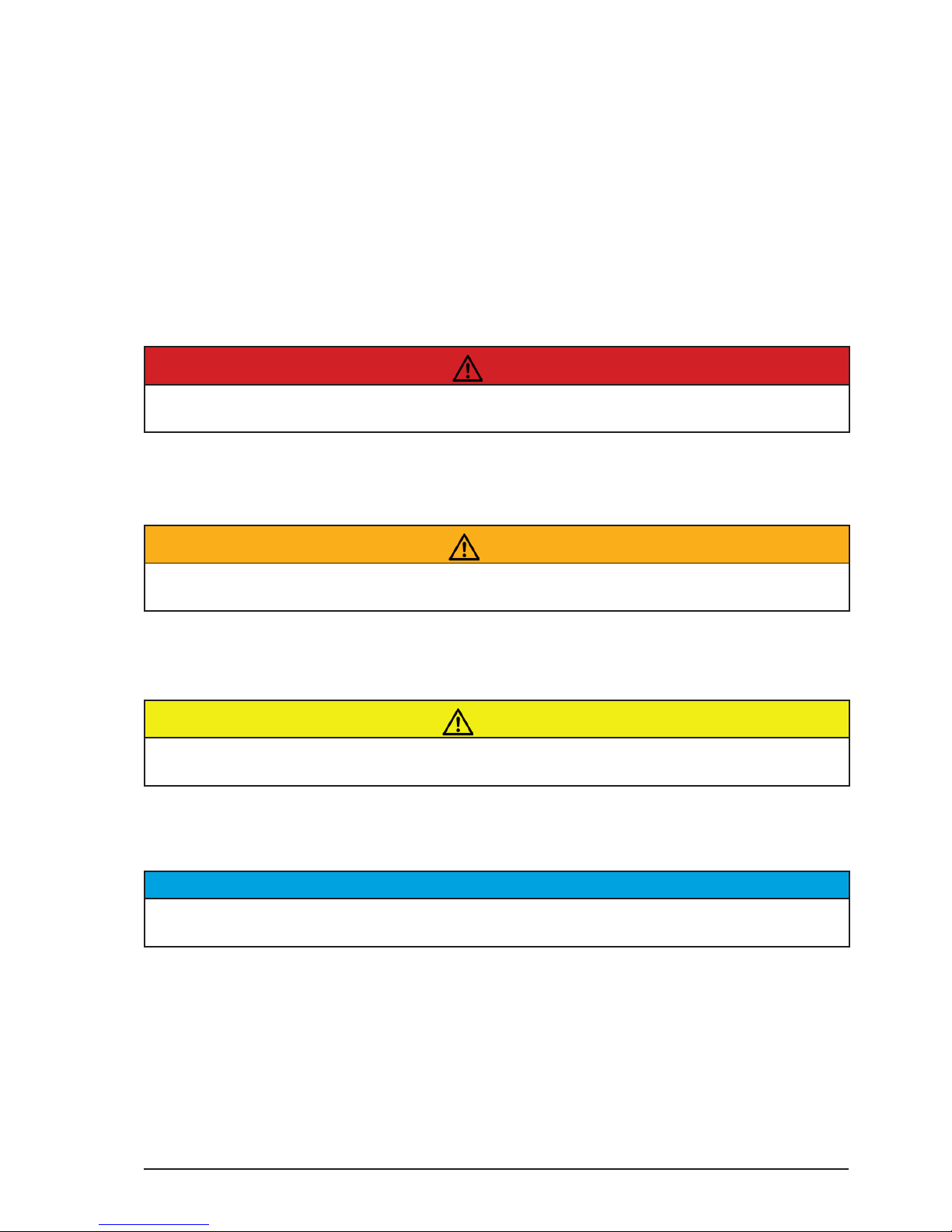
Risk levels and alert symbols
Safety warnings, safety alert symbols, and signal words in these instructions indicate dierent
risk levels:
Danger!
DANGER indicates an imminent hazardous situation which, if not avoided, will result in death
or serious injury.
Warning!
WARNING indicates a potentially hazardous situation which, if not avoided, may result in
death or serious injury.
CAUTION!
CAUTION indicates a potentially hazardous situation which, if not avoided, may result in minor
or moderate injury.
NOTICE
NOTICE explains practices not related to physical injury. No safety alert symbol appears with
this signal word.
Note: Provides additional information to clarify or simplify a procedure.
Page 9
All content © 2018, cmotion GmbH. All specications are subject to change without further notice.
http://www.cmotion.eu
page 9 of 80
Vital precautions
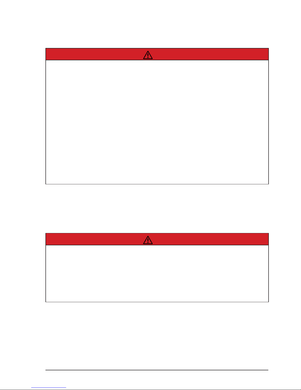
Danger!
Risk of electric shock and re!
Short-circuits may result in serious damage to equipment, injury or death.
Before use, read and follow all valid instructions.
Use solely and exclusively as described in the instructions.
Never open. Never insert objects unless instructed to do so. E.g. battery, USB.
For operation, always use a power source as indicated in the instructions.
Always unplug the cable by gripping the plug, not the cable.
Never try to repair. All repair work should be done by a qualied cmotion Service Center.
Never remove or deactivate any safety equipment (incl. warning stickers or paintmarked
screws).
Always protect from moisture, cold, heat, dirt, vibration, shock, or aggressive substances.
Danger!
Risk of re!
Short-circuits and back currents to power supplies/batteries may result in serious damage to
equipment, injury or death.
Always use original ARRI/cmotion LBUS cables to external power sources (D-Tap, XLR)!
ARRI/cmotion LBUS cables to external power sources provide a protection circuit to prevent
back currents to power supplies/batteries.
Page 10
All content © 2018, cmotion GmbH. All specications are subject to change without further notice.
http://www.cmotion.eu
page 10 of 80
2. Audience and intended use
NOTICE
The product is solely and exclusively available for commercial customers and shall be used by
skilled personnel only. Every user should be trained according to cmotion guidelines. Use the
product only for the purpose described in this document. Always follow the valid instructions
and system requirements for all equipment involved.
Note: The cPRO hand unit is solely and exclusively for use on professional camera setups.
3. Scope of delivery and
warranty
NOTICE
Product and packaging contain recyclable materials. Always store, ship, and dispose of
according to local regulations.
cmotion is not liable for consequences from inadequate storage, shipment or disposal.
Delivery
On delivery, please check that the package and content are intact. Never accept a damaged or
incomplete delivery. A complete delivery includes:
■ cPRO hand unit unit with antenna
■ Plain white focus ring for cPRO hand unit
■ Plain white iris strip for cPRO hand unit
■ ctruss - connection point for cstrap
■ User manual download card
■ Original packaging
Warranty
For scope of warranty, please ask your local cmotion Service Partner. cmotion is not liable
for consequences from inadequate shipment, improper use or damage through third-party
products.
Page 11
All content © 2018, cmotion GmbH. All specications are subject to change without further notice.
http://www.cmotion.eu
page 11 of 80
4. Introduction
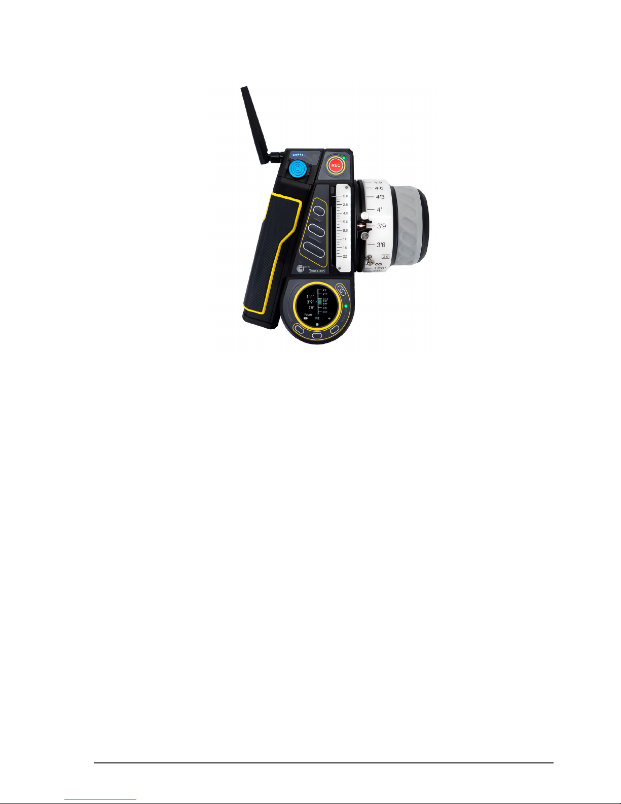
The cPRO hand unit is the wireless hand-held control unit of the cPRO lens control system with
an integrated red-coded cmotion radio module. With its user friendly and intuitive interface the
cPRO hand unit is lightweight and sets new standards in both design and ergonomics.
The focus knob oers an ergonomic grip with a ngertip concave mold and mechanical hard
stops.
6 user buttons provide quick access to cPRO’s extensive features. Iluminated key elements
(focus marker ring, iris slider strip and buttons) oer ideal operation even in dark environments.
The capacative touch display shows live lens and camera information.
The asymmetrical design and comfort grip keeps the hand unit balanced in your hand. Several
well positioned mounting points provide options for third party accessories including quick
release mounts, monitors, etc.
With optional network licensing, up to three cPRO hand units can connect to a cPRO motor /
cPRO camin for split focus, iris and zoom operation (available with Software Release Package
v2.0 / license required for each hand unit). Real-time lens data is available when used with the
cPRO motor / cPRO camin.
Using the LBUS interface, the cPRO hand unit can be hard-wired with up to three additional
cforce motors and other ARRI / cmotion control units including the pan-bar / steady zoom,
ARRI LCUBE-1, LCUBE-2, ARRI Master Grips or cnder III.
Page 12

All content © 2018, cmotion GmbH. All specications are subject to change without further notice.
http://www.cmotion.eu
page 12 of 80
Main features:
■ Ergonomic and balanced design
■ Extensive software features for creative FIZ control
■ Supports lens data with cPRO motor / cPRO camin
■ Touch display for menu navigation and settings
■ Intuitive thumb wheel for menu navigation, settings and 4th axis control (available
with Software Release Package v2.0.)
■ Illuminated pre-marked focus rings and iris strips with LED status feedback
■ Illuminated, user assignable buttons
■ Vibrating function
■ USB for external power source, updates and transfer of lens les and user settings
■ Mounting options for accessories like cstrap, monitor bracket or v-lock plate
■ Adjustable mechanical hard stops
■ Panic button for mechanical hard stop override
■ Integrated cmotion red radio module
■ Daisy-chain compatible via LBUS for hard-wired operation
■ Lightweight (less than 900g (approx 31 oz) incl. battery and antenna)
4.1. LBUS connector
LBUS is a bus standard designed to allow multiple lens motors and control devices to
communicate with each other. Up to three cforce-type motors can be chain-linked in a row.
Each cforce motor has two identical, bi-directional LBUS interfaces providing power and
control signals to the motor. For hard-wired operation the cPRO hand unit can be connected
to the daisy-chain through its LBUS interface using any LBUS to LBUS cable.
4.2. CAM interface
The cPRO hand unit does not have a CAM interface itself. But, the CAM interface on the cPRO
motor / cPRO camin is also a fully functional LBUS connector. As such, it allows multiple
lens motors and control devices to communicate with each other through K2.0015760 Cable
CAM (7p) - LBUS. Using this cable the cPRO hand unit can also be connected to the daisy-
chain through its LBUS interface for hard-wired operation.
In addition, the CAM interface on the cPRO motor / cPRO camin oers a versitile interface
for camera control. There are several camera interface cables available which, depending
on the camera, oer start-stop control with feedback, camera status, tally and even camera
control. (License required to control camera settings / available with Software Release
Package v2.0).
If a camera is detected in the LBUS daisy-chain, camera data and camera feedback will be
displayed on the cPRO hand unit.
Page 13
All content © 2018, cmotion GmbH. All specications are subject to change without further notice.
http://www.cmotion.eu
page 13 of 80
5. cPRO hand unit hardware layout
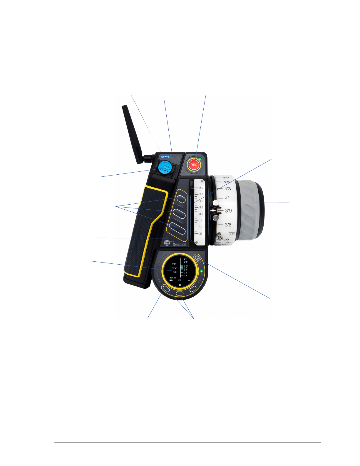
5.1. Hardware layout overview
1 Joystick
2 User buttons
3 Light sensor
4 Touch display
5 Thumb wheel
6 Menu buttons
7 HOME button
8 Knob
9 Slider
10 REC button
11 Joystick indicator display
12 Back button
1
2
3
4
5 6
7
8
9
10
11
12
Page 14
All content © 2018, cmotion GmbH. All specications are subject to change without further notice.
http://www.cmotion.eu
page 14 of 80
5.2. Control interface
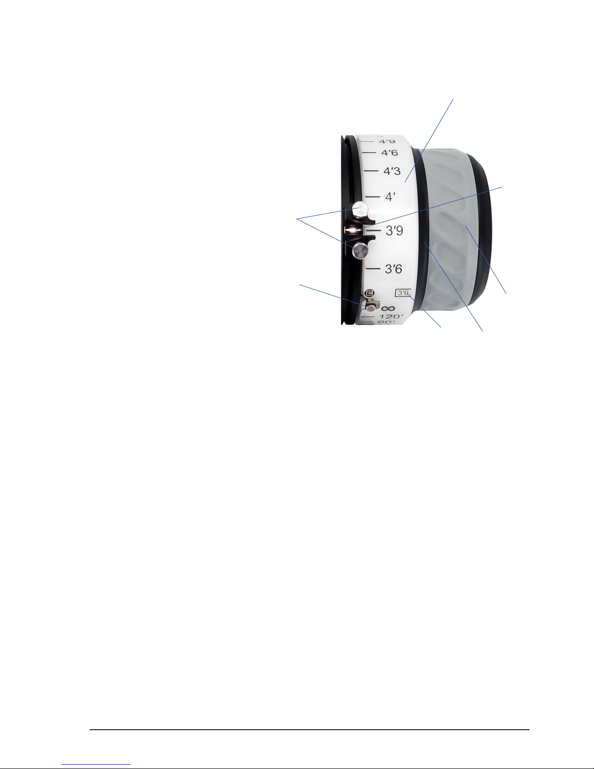
5.2.1. Knob
1 Mechanical hard stops
2 Panic button
3 Pre-marked focus ring
4 Fingertip concave mold
5 Anti-slip grip
6 Datum line
7 Knob illumination /
status LEDs
The knob is a control interface with an absolute position encoder. Turn the knob clockwise
or counter-clockwise to control the assigend axis. As default the knob is assigned to focus.
5.2.1.1. Mechanical hard stops
The cPRO knob has two mechanical hard stops, which can be adjusted freely around the
knob barrel. The hard stops allow you to move the knob between two focus positions
precisely.
In oder to adjust your long focus distance
- match the desired long focus distance position to the datum line of the knob
- open the thumbscrew on the upper hard stop and slide the hard stop around
the knob barrel until it hits the panic button.
- lock the hard stop position by turning the thumbscrew clockwise
In oder to adjust your close focus distance
- match the desired close focus distance position to the datum line of the knob
- open the thumbscrew on the lower hard stop and slide the hard stop around
the knob barrel until it hits the panic button.
- lock the hard stop position by turning the thumbscrew clockwise
1
2
3 4
5
6
7
Page 15
All content © 2018, cmotion GmbH. All specications are subject to change without further notice.
http://www.cmotion.eu
page 15 of 80
5.2.1.2. Panic button
The cPRO panic button is a unique feature of the cPRO hand unit. It allows you to
overwrite the mechnical hard stops without adjusting the predened focus range. E.g.
when shooting the slate outside of the predened focus range, or the actor misses their
mark.
In order to override the mechanical hard stops temporarily, simply press the panic button
and dive underneath the desired hard stop.
In order to disable the mechanical hard stops, press and turn the panic button clockwise
or counter-clockwise. To re-enable the mechanical hard stops, press and turn the panic
button back to its 90° home position.
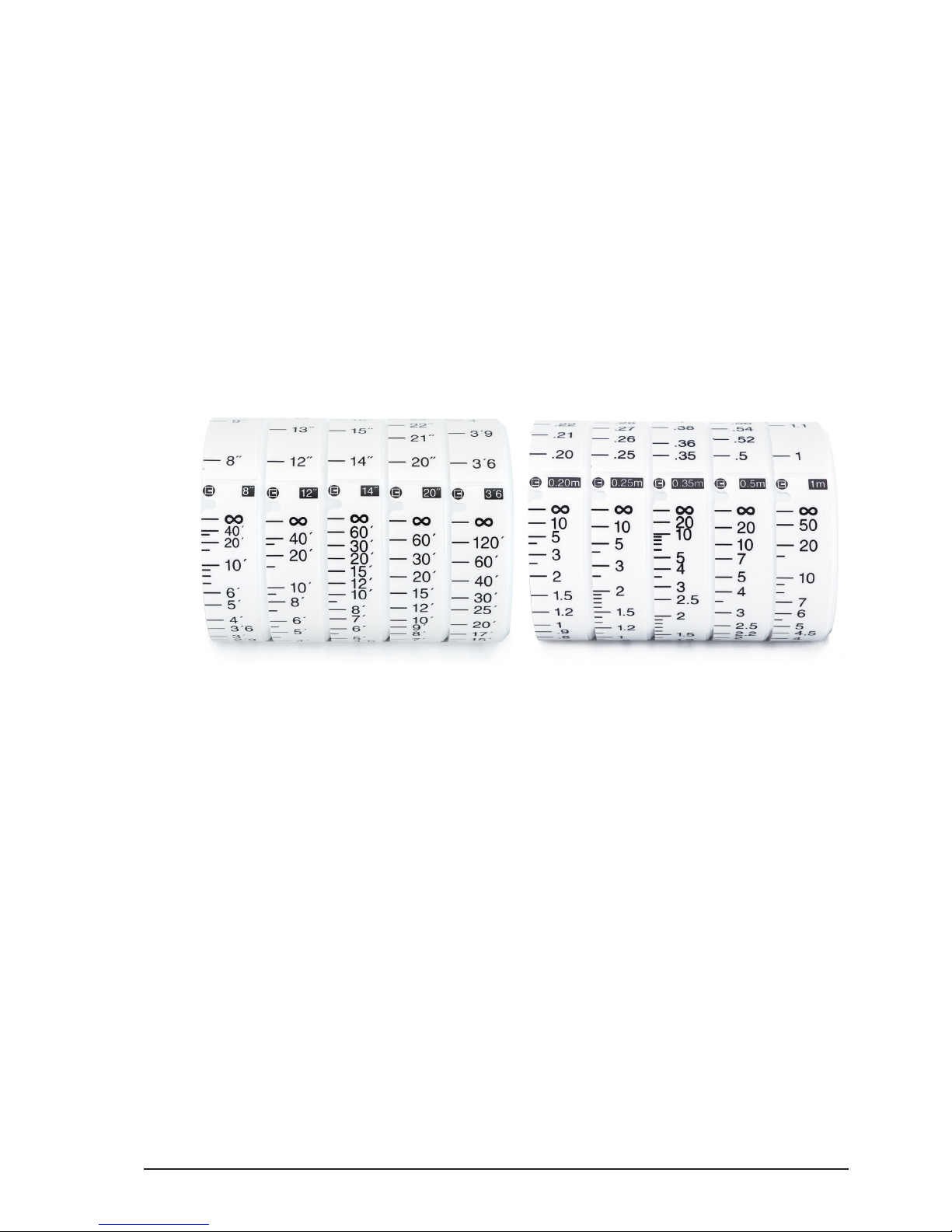
5.2.1.3. Pre-marked focus rings
In order to save time marking your focus rings for each lens, the cPRO hand unit oers
ve imperial and ve metric pre-marked rings. Each ring is engraved with a scale from
innity to one of ve close focus values and can be used with a wide range of lenses from
wide angle to telelphoto. For more information please refer to section “6.2.3.2.1.3. Premarked rings” on page 39 in this manual.
5.2.1.4. Datum line
The datum line is the reference mark on the knob. It illuminates with the knob scale
illumination. Its brightness can be controlled in the “Knob brightness” menu.
5.2.1.5. Knob illumination and status LEDs
The knob scale can be illuminated individually through the “Knob brightness” menu.
The status LEDs for the knob are built into the scale illumination, which gives you direct
feedback of the status for the knob axis.
K2.0019834 cPRO pre-marked focus
ring imperial set
K2.0019835 cPRO pre-marked focus
ring metric set
Page 16
All content © 2018, cmotion GmbH. All specications are subject to change without further notice.
http://www.cmotion.eu
page 16 of 80
LED status Meaning
o no axis assigned to knob / knob illumina-
tion o
solid white motor ready, no warnings /knob illumina-
tion on
solid green motor ready, no warnings, limits set
green/yellow ashing calibration request
yellow ashing motor calibration
solid yellow calibration time out
solid red no motor connected
red ashing knob locked / no motor control
5.2.2. Slider
1 Slider
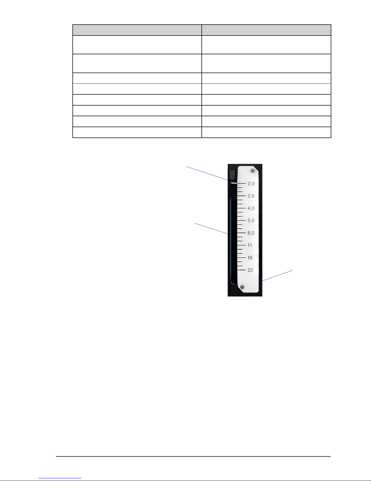
2 Pre-marked iris strip
3 Slider illumination / status LEDs
The slider is a control interface with an absolute position encoder. Move the slider up or
down to control the assigned axis. As default, the slider is assigned to iris.
5.2.2.1. Pre-marked iris strips
In order to save time marking your iris strips for each lens, the cPRO hand unit oers
three pre-marked strips. Each strip is engraved with a scale from close or 22 to one of
three wide open iris values. For more information refer to section “6.2.3.2.2.2. Pre-marked
strips” on page 40 in this manual.
5.2.2.2. Slider illumination and status LEDs
The slider scale can be illuminated individually through the “Slider brightness” menu.
The status LEDs for the slider are built into the scale illumination, which gives you direct
feedback of the status for slider axis.
1
2
3
Page 17
All content © 2018, cmotion GmbH. All specications are subject to change without further notice.
http://www.cmotion.eu
page 17 of 80
LED status Meaning
o no axis assigned to slider / slider illumina-
tion o
solid white motor ready, no warnings /slider illumina-
tion on
solid green motor ready, no warnings, limits set
green/yellow ashing calibration request
yellow ashing motor calibration
solid yellow calibration time out
solid red no motor connected
red ashing slider locked / no motor control
5.2.3. Joystick
1 Joystick
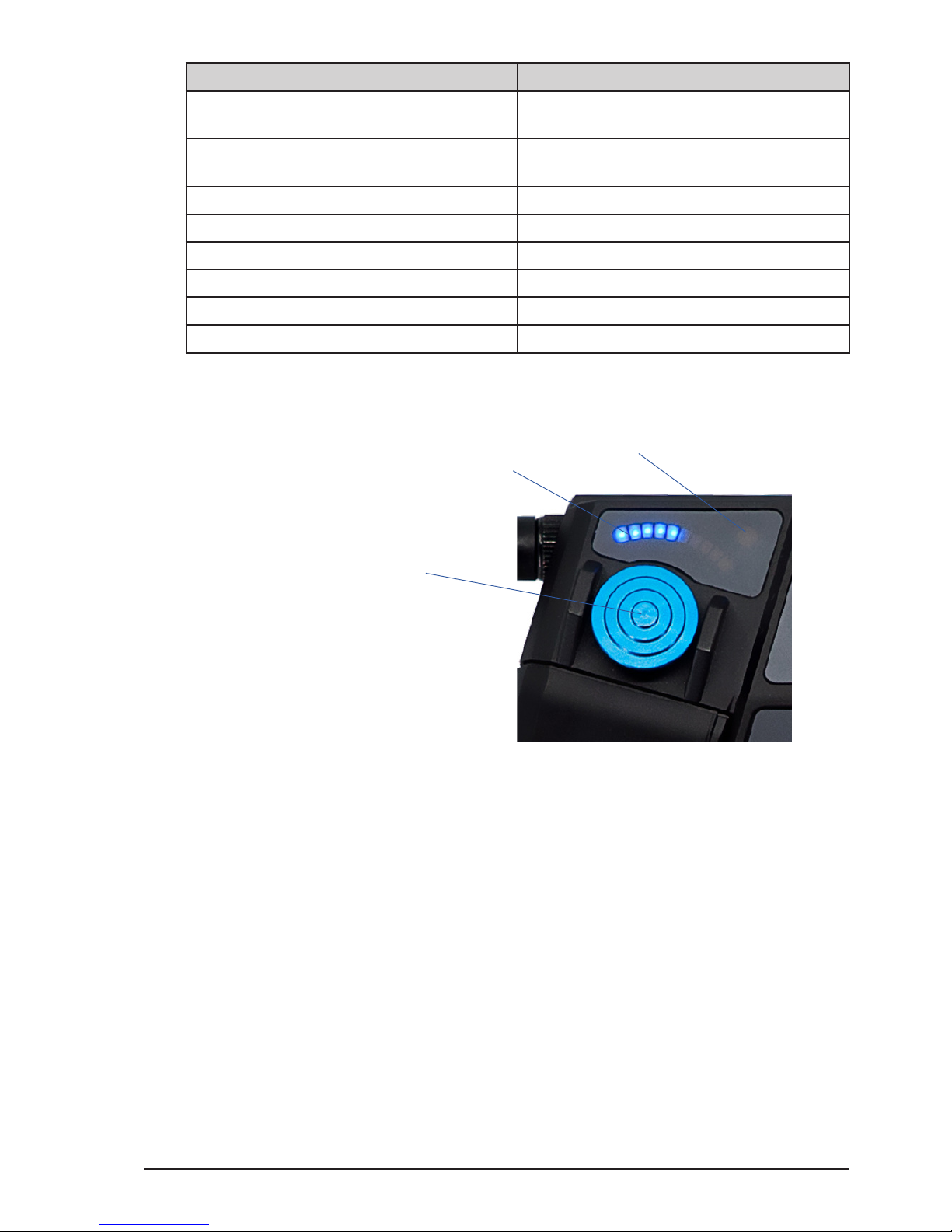
2 Position indicator display
3 Joystick status LED
The joystick is a control interface with a relative position encoder. Press the joystick up or
down to control the assigned axis. The joystick´s touch sensitivity and the axis speed can be
adjusted individually in the “Joystick menu” (please refer to section “6.2.3.2.3. Joystick” on
page 41 in this manual). As default, the joystick is assigned to zoom.
5.2.3.1. Position indicator display
The position indicator display consits of 10 blue single LEDs. It indicates the relative
position of the assigned axis in %. If the display is o, the motor is at one end stop of the
lens (= < 10%). If the display is fully illuminated the motor is at the other end stop of the
lens 100%. The joystick position indicator display can be illuminated individually through
the “Joystick brightness” menu. As default, the joystick is assigned to zoom.
5.2.3.2. Joystick status LED
The status LED for the joystick is a seperate LED above the position indicator display. This
gives you direct feedback of the status of the joystick axis.
2
1
3
Page 18
All content © 2018, cmotion GmbH. All specications are subject to change without further notice.
http://www.cmotion.eu
page 18 of 80
LED status Meaning
o no axis assigned to joystick / joystick illu-
mination o
solid green motor ready, no warnings, limits set
green/yellow ashing calibration request
yellow ashing motor calibration
solid yellow calibration time out
solid red no motor connected
red ashing joystick locked / no motor control
5.2.4. Thumb wheel
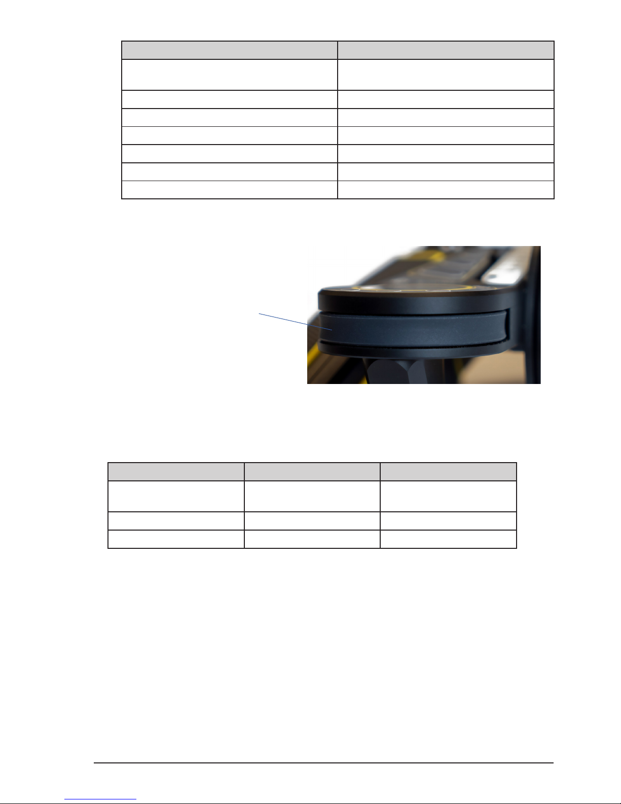
1 Thumb wheel
The thumb wheel is a unique control interface of the cPRO hand unit with a relative position
encoder. It allows you to navigate through all the menu pages comfortably even when wearing
gloves. It is even possible to assign the thumb wheel as a 4th axis controller (available with
Software Release Package v2.0).
NAVIGATION Thumb wheel gesture Function
in main screens scroll clockwise / scroll
counter-clockwise
scroll through horizontal
menu and display screens
in adjustment menu scroll clockwise navigate up
scroll counter-clockwise navigate down
5.2.5. Buttons / camera status LED
With the exception of the REC button, the HOME button and menu button 2 (MB2), all
buttons on the cPRO hand unit can be assigned individually. And, all buttons except the
back button (BB1) illuminate once assigned to a user function.
User button functions*:
O / Focus limits set / Iris limits set / Zoom limits set / Focus calibration / Iris calibration /
Zoom calibration / Calibration all / ZAP / Joystick speed up / Joystick speed down / Autofocus
press / Autofocus toggle / Autofocus pinpoint / System unit / Steath mode / Laser pointer /
Camera rec / Lock knob / Lock slider / Lock joystick / Lock thumb wheel
*(more user button functions available with Software Release Package v2.0)
1
Page 19
All content © 2018, cmotion GmbH. All specications are subject to change without further notice.
http://www.cmotion.eu
page 19 of 80
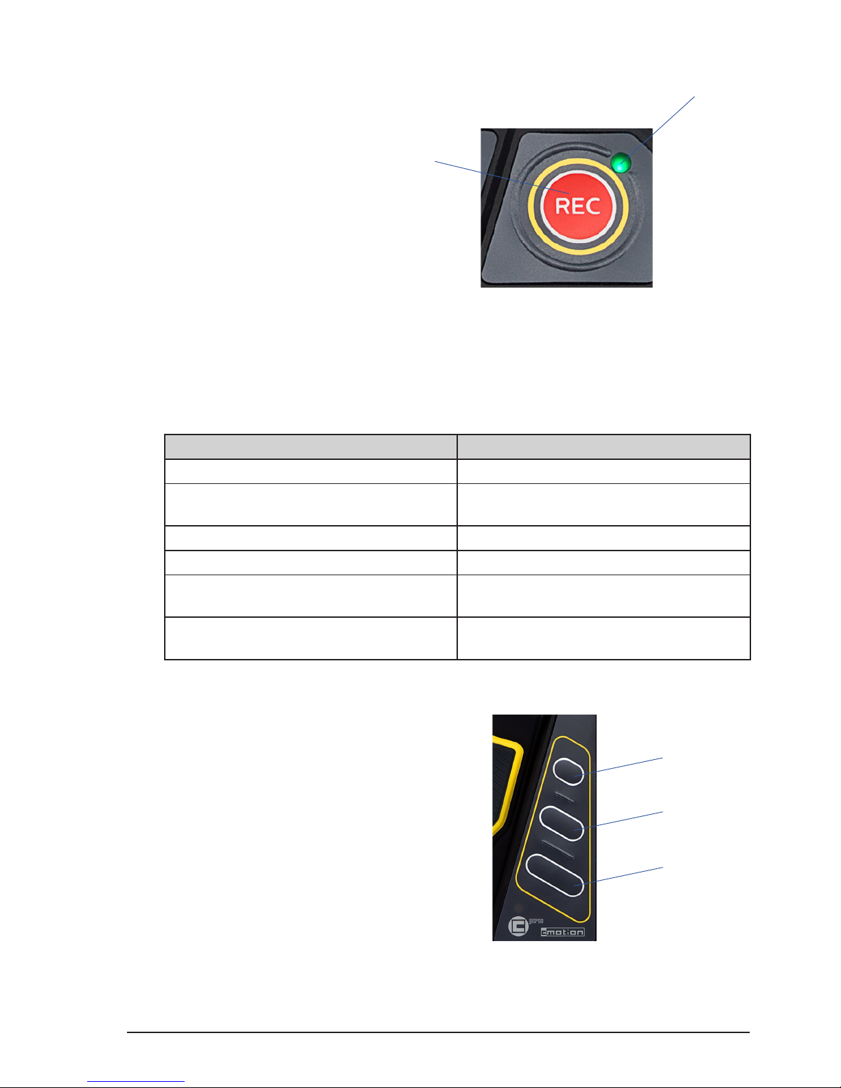
5.2.5.1. REC button and camera status LED
1 REC button
2 Camera status LED
The REC button is assigend to “Camera rec” only and cannot be changed. Anyways the
“Camera rec” function can be assigned to any other user button.
The camera status LED is next to the REC button and gives direct feedback of the camera
status.
LED status Meaning
o no camera interface is available
solid green camera interface is available / camera
ready
solid red camera is recording
red / green ashing camera is in idle mode (camera not ready)
red ashing slow remaining record time is less than ve
minutes
red ashing fast remaining record time is less than one
minute
5.2.5.2. User buttons
1 User button 1 (UB1)
2 User button 2 (UB2)
3 User button 3 (UB3)
All user buttons (UB1/UB2/UB3) in the center of the cPRO hand unit can be assigned
individually. Once assigned to a user function, each assigned button will illuminate
individually unless keypad brightness is set at 0.
1
2
1
2
3
Page 20
All content © 2018, cmotion GmbH. All specications are subject to change without further notice.
http://www.cmotion.eu
page 20 of 80
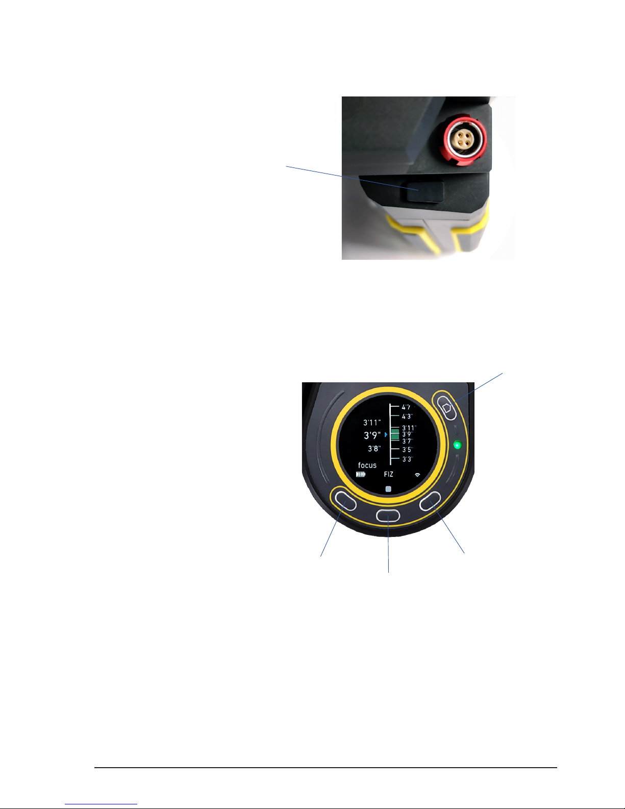
5.2.5.3. Back button
1 Back button (BB1)
The back button is located on the hand grip of the cPRO hand unit, underneath the LBUS
connector. It is not illuminated but can be assigned individually to any user function.
5.2.5.4. Menu buttons
1 Menu button 1 (MB1)
2 Menu button 2 (MB2)
3 Menu button 3 (MB3)
4 HOME Button
3 menu buttons are located around the touch screen. And, with the exception of MB2,
can be assigned to any user function while displaying one of the main screens. When
entering the adjustment menu the menu buttons will change their behaviour and show
their function on the touch display.
5.2.5.4.1. MB2 (QUICK NAV)
Menu button 2 (MB2) is permanently assigned to allow quick navigation between main
screens with multiple pages, and from specic main screens directly into the related
adjustment menu. MB2 is illuminated permanently if the keypad brightness is not set at 0.
1
1
2
3
4
Page 21
All content © 2018, cmotion GmbH. All specications are subject to change without further notice.
http://www.cmotion.eu
page 21 of 80
5.2.5.4.2. Quick navigation between main screens
Some of the main screens consist of multiple pages. In order to navigate vertically within
a main screen or menu, press menu button 2 (MB2) repeatedly. As an alternative, you can
also swipe the touch screen up or down.
For an overview of which main screens consist of multiple pages, please refer to section
“6.1. GUI main screen overview” on page 23 in this manual.
5.2.5.4.3. Quick navigation main screens to adjustment menu
In order to use the quick navigation to enter related adjustment menus from the main
screens, press and hold menu button 2 (MB2). As an alternative, you can also tap and
hold the touch display.
5.2.5.5. HOME button
The HOME button has various functions and is illuminated permanently if the keypad
brightness is not set at 0.
NAVIGATION HOME button Function
cPRO hand unit is o press short turn on the cPRO hand
unit
cPRO hand unit is on press long (3 seconds) turn o the cPRO hand
unit
from main screens press short twice enter the adjustment menu
from adjustment menu press short return to the main screen
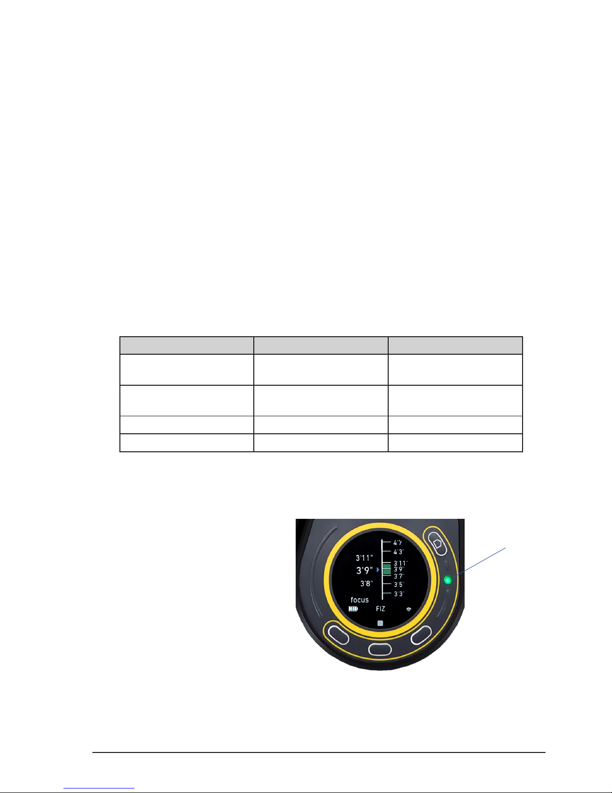
5.2.5.6. System status LED
1 System status LED
The sytem status LED indicates the status of the cPRO hand unit.
1
Page 22
All content © 2018, cmotion GmbH. All specications are subject to change without further notice.
http://www.cmotion.eu
page 22 of 80
LED status Meaning
solid green radio turned on and device connected
wireless / radio o and device connected
through the LBUS port (hard-wired)
solid red initialising state / hardware error
red / green ashing radio turned on and device not connected
wireless / radio turned o and device not
connected through the LBUS port (hardwired)
red ashing battery low / no free RF channel available
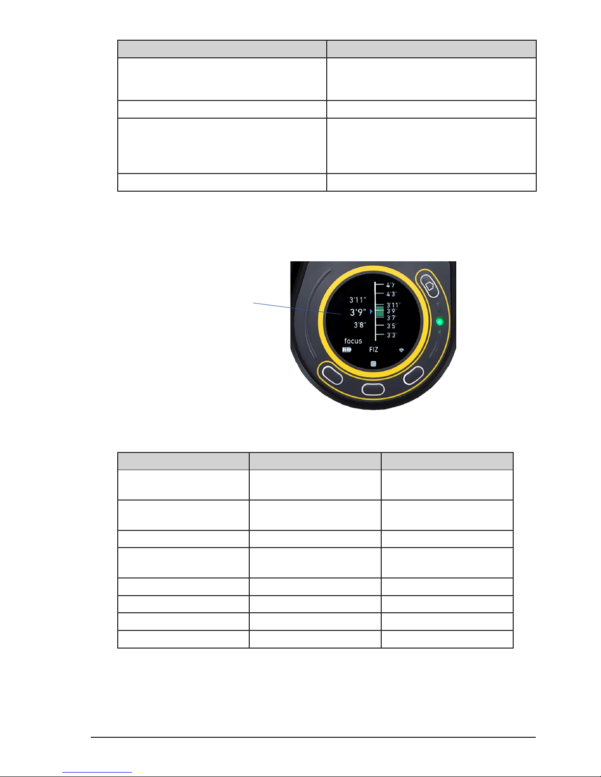
5.2.6. Touch screen
1 Capacitive touch display
The cPRO hand unit features a multicolor 1.22” QVGA capacitive TFT touch display.
NAVIGATION Touch screen gesture Function
in main screens swipe left / swipe right switch between the main
screens horizontally
swipe up / swipe down switch between the main
screens vertically
tap short twice enter the adjustment menu
tap and hold enter related adjustment
menu
in adjustment menu swipe up navigate down
swipe down navigate up
swipe left / tap short enter sub menu (select)
swipe right leave sub menu (back)
1
Page 23
All content © 2018, cmotion GmbH. All specications are subject to change without further notice.
http://www.cmotion.eu
page 23 of 80
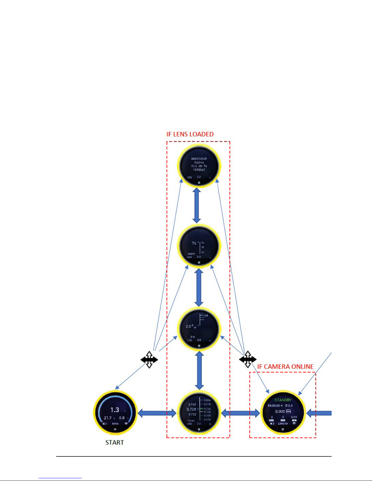
6. cPRO hand unit software layout
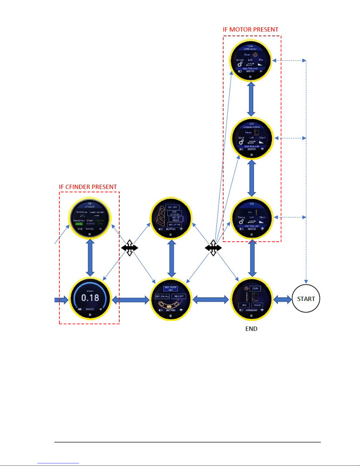
6.1. GUI main screen overview
The cPRO hand unit features a user interface to congure the system. The touch sensitive
display shows menu and status information and can be used to navigate through the main
screens and the adjustment menu. As an alternative, the thumb wheel and the menu buttons
can be used to navigate and to change settings as well e.g. if wearing gloves.
If a new LBUS device is connected to the daisy-chain, the corresponding device main screen
will show up automatically. Device specic capabilities will be enabled within the adjustment
menu.
Page 24
All content © 2018, cmotion GmbH. All specications are subject to change without further notice.
http://www.cmotion.eu
page 24 of 80
Page 25
All content © 2018, cmotion GmbH. All specications are subject to change without further notice.
http://www.cmotion.eu
page 25 of 80
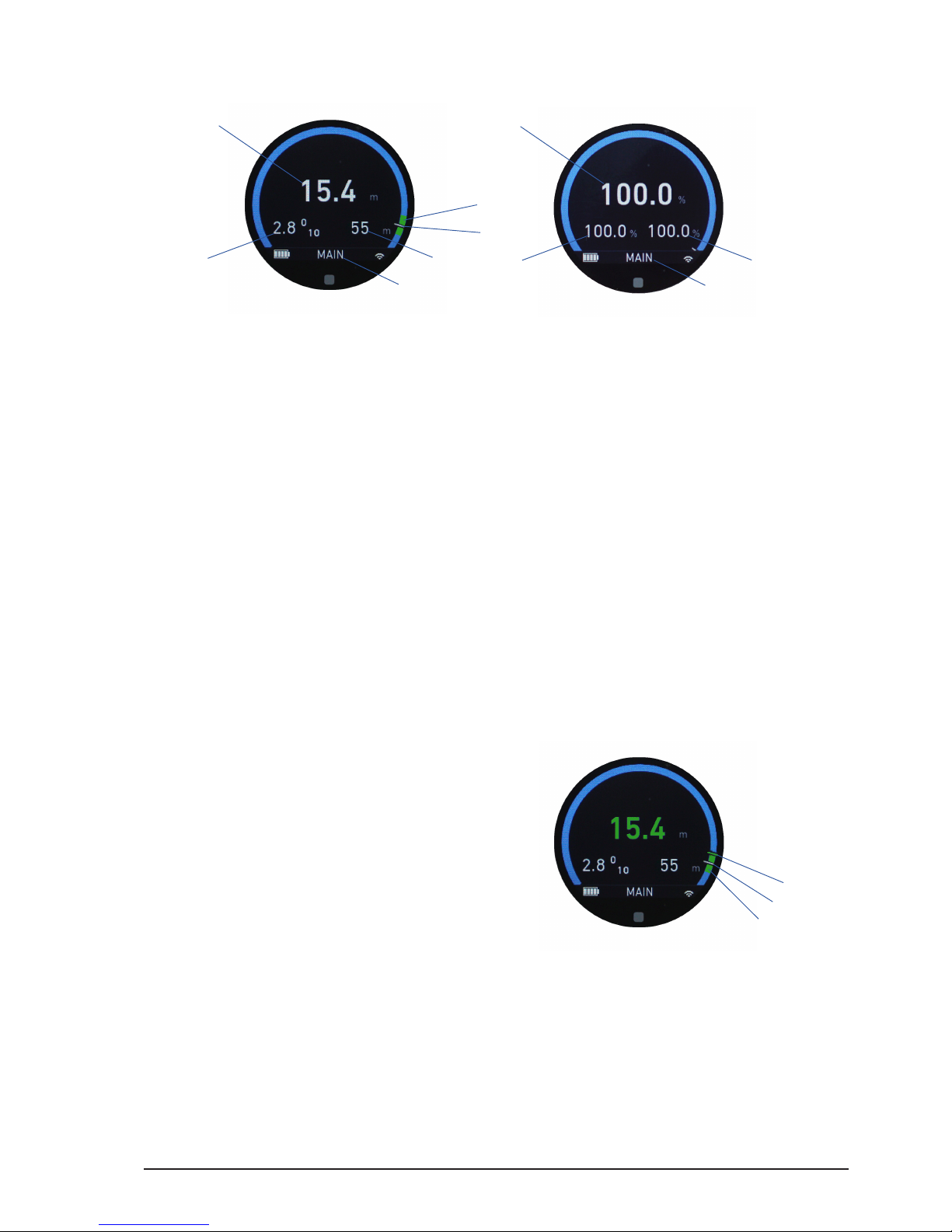
6.1.1. MAIN screen
MAIN screen if lens le loaded
MAIN screen if no lens le loaded
1 Focus information (value/percentage)
2 Iris information (value/percentage)
3 Zoom information (value/percentage)
4 Depth of eld range
5 Actual focus position
6 Status bar (with battery status and RF signal strength)
The MAIN screen shows compact focus, iris and zoom information on a simple GUI. If a
lens le is loaded, it shows the actual focus, iris, zoom values and the depth of eld range.
If no lens le is loaded, it shows the motor position as a percentage of the calibration
range.
The status bar on all main screens shows information about the main screen page, battery
status, wireless signal strength or, if one of the control interfaces is locked.
Note: If a rangender is attached to the LBUS daisy-chain, and the measured rangender
distance is within depth of eld (DOF), the focus value will turn green. Otherwise it illuminates
white.
1 Measured rangender distance
2 Actual focus position
3 Depth of eld range
6.1.2. FIZ main screen
The FIZ screen is only enabled if a lens le is loaded. It displays detailed focus information
including a focus scale with depth of eld (DOF), a full iris and zoom scale and information
about the loaded lens le.
Note: The lens adjustment menu can be reached from all FIZ main screens quickly by tapping
and holding the touch display or by pressing and holding menu button 2 (MB2).
3
2
1
6
6
1
4
5
3
2
1
2
3
Page 26
All content © 2018, cmotion GmbH. All specications are subject to change without further notice.
http://www.cmotion.eu
page 26 of 80
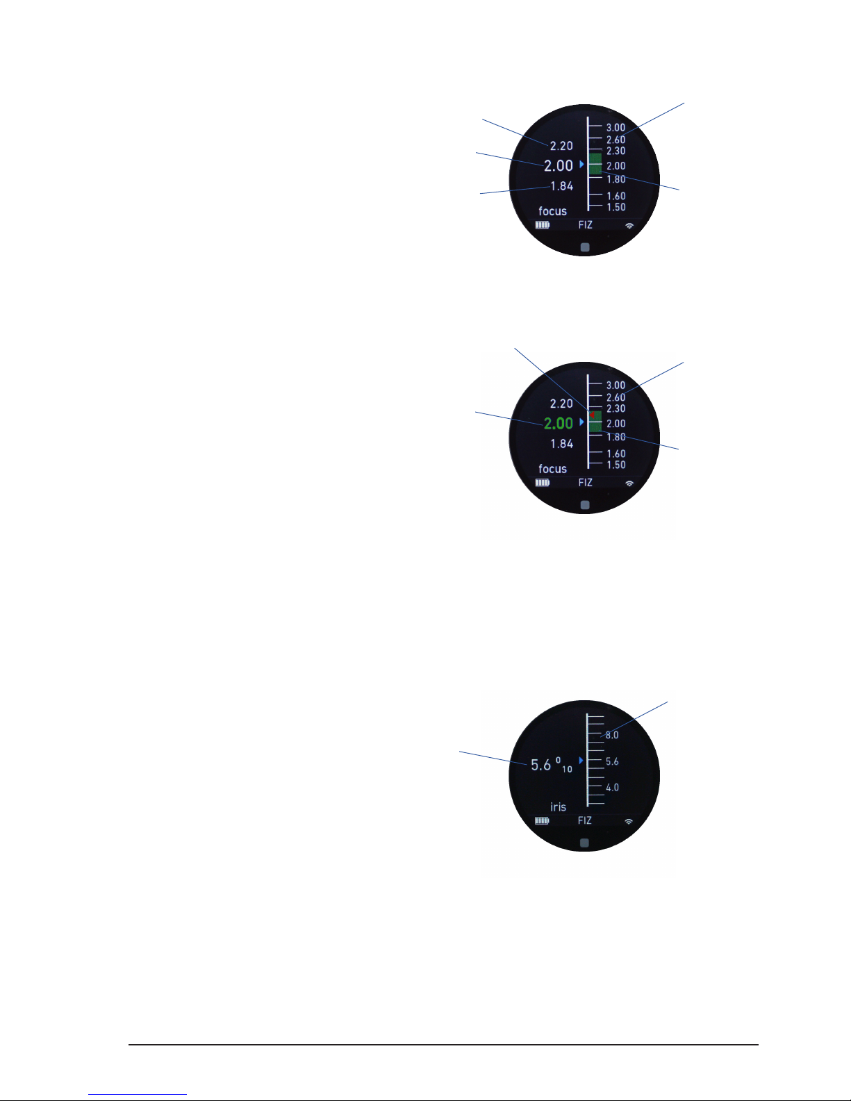
6.1.2.1. Focus main screen
1 Actual focus position (value)
2 Focus scale
3 DOF far limit (value)
4 DOF close limit (value)
5 DOF range
The focus main screen displays a full focus scale, as well as depth of eld (DOF) information
gracally and numerically.
1 Actual focus position (value)
2 Measured rangender distance
2 Focus scale
3 DOF range
Note: If a rangender is attached to the LBUS daisy-chain, and the measured rangender
distance is within depth of eld (DOF), the focus value will turn green. Otherwise it illuminates
white.
6.1.2.2. Iris main screen
1 Actual iris position (value)
2 Iris scale
The iris main screen displays a full iris scale gracally and numerically. T-stops are
displayed in 1/10 increments.
1
2
3
4
5
1
3
2
4
1
2
Page 27
All content © 2018, cmotion GmbH. All specications are subject to change without further notice.
http://www.cmotion.eu
page 27 of 80
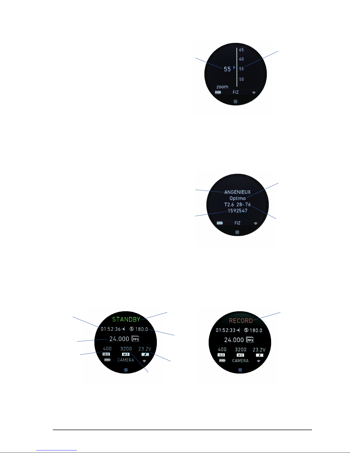
6.1.2.3. Zoom main screen
1 Actual zoom position (value)
2 Zoom scale
The zoom main screen displays a full zoom scale gracally and numerically.
6.1.2.4. Lens information main screen
1 Brand
2 Lens name
3 T-stop / zoom range
4 Serial number
The lens information main screen displays all the relevant information about the loaded
lens le, including brand, model, T-stop, zoom range and serial number.
6.1.3. Camera main screen
1 Camera record information
2 Remaining record time
3 Shutter speed
4 Frames per second (FPS)
5 ISO
6 White balance
7 Camera battery status
2
1
4
2
1
3
1
4
6
2
3
1
5
7
Page 28
All content © 2018, cmotion GmbH. All specications are subject to change without further notice.
http://www.cmotion.eu
page 28 of 80
The camera information main screen is enabled automatically, as soon as a camera is
detected in the daisy-chain. The camera needs to be connected to the CAM interface of
the cPRO motor or the cPRO camin. Camera status information can be displayed for the
most popolar cameras such as ARRI, RED, SONY, BLACKMAGIC or CANON. Depending
on the camera brand and model, dierent functions including start-stop control and record
feedback, camera status, tally and control of camera settings are available. (License
required to control camera settings / available with Software Release Package v2.0)
6.1.4. Rangender main screens
The rangender main screens are enabled automatically when a rangender is detected
in the LBUS daisy-chain and a lens le is loaded. The rangender main screens consits of
a rangender overview and a rangender settings screen.
Note: The rangender adjustment menu can be accessed from both rangender main
screens quickly by tapping and holding the touch display or by pressing and holding the
menu button 2 (MB2).
6.1.4.1. Rangender overview screen
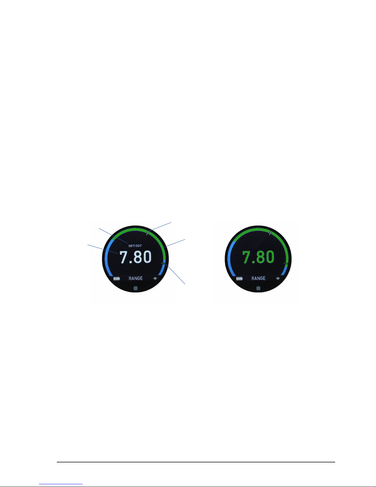
1 Measured rangender distance (value)
2 Measured rangender distance (position)
3 Actual focus position
4 DOF range
5 Rangender sensor warning
The rangender overview screen displays the rangender information gracally and
numerically.
Note: The numeric rangender distance value will turn green if the measured rangender
distance is within the depth of eld.
Note: When using cmotion’s cnder III, the rangenders sensor warning will show up if no
vaild measuring is possible. (Please refer to the cnder III user guide)
2
4
3
1
5
Page 29
All content © 2018, cmotion GmbH. All specications are subject to change without further notice.
http://www.cmotion.eu
page 29 of 80
6.1.4.2. Rangender settings screen
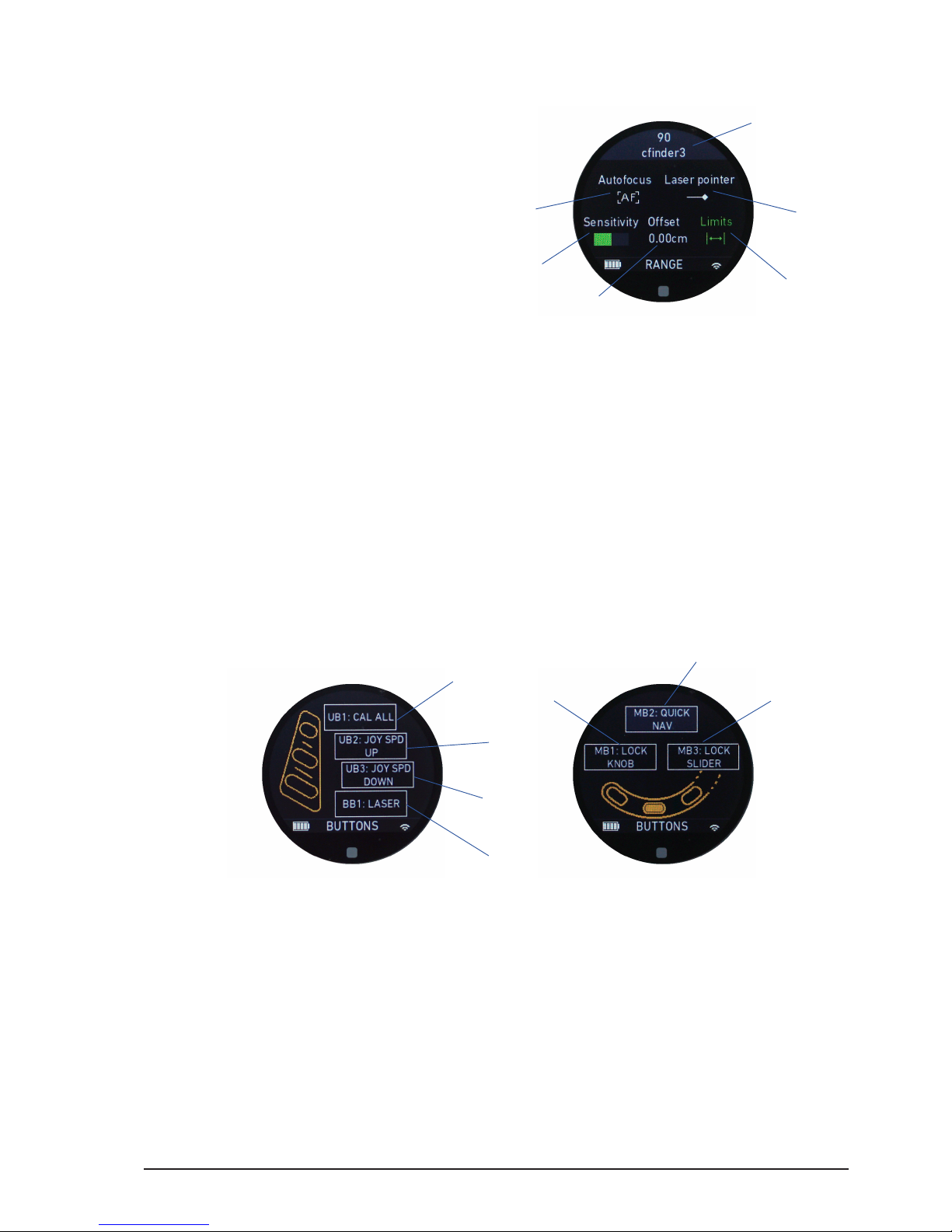
1 Autofocus (on/o)
2 Laser pointer (on/o)
3 Sensitivity settings
4 Oset (value)
5 Rangender limits (on/o)
6 LBUS device ID (serial number/name)
Autofocus: The autofocus icon will turn green if autofocus is on. If autofocus is o, it
illuminates white.
Laser pointer: The laser pointer icon will turn green if the laser pointer is on. If the laser
pointer is o, it illuminates white.
Sensitivity: Shows the sensitivity settings gracally.
Oset: The oset icon will turn green if an oset is set to a value other than 0, and will
display the oset value numerically.
Limits: The limits icon will turn green if a rangender limit other than “limit max” = innity
or “limit min” = 0 is set. Otherwise, the icon will illuminate white.
6.1.5. Buttons main screens
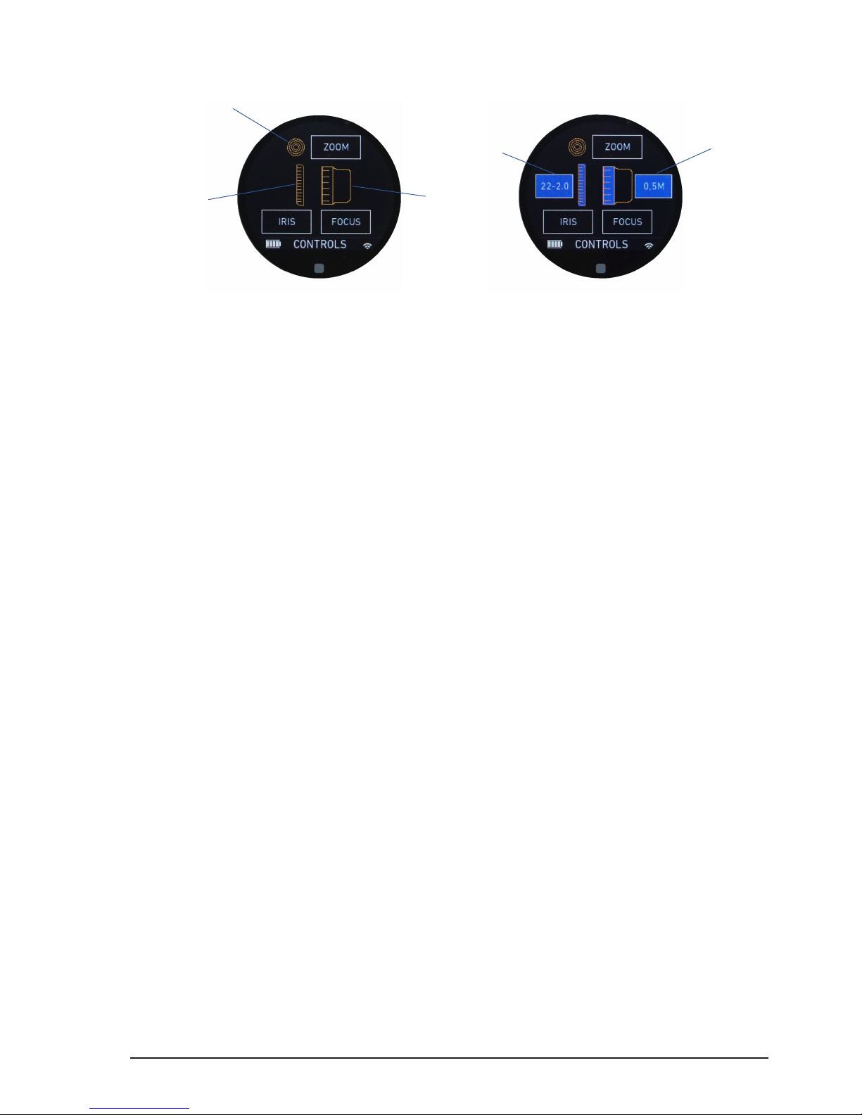
1 User button 1 / UB1 (function)
2 User button 2 / UB2 (function)
3 User button 3 / UB3 (function)
4 Back button 1 / BB1 (function)
5 Menu button 1 / MB1 (function)
6 Menu button 2 / MB2 (QUICK NAV))
7 Menu button 3 / MB3 (function)
The buttons main screens display the functions assigned to each user button.
Note: The buttons adjustment menu can be accessed from both buttons main screens
quickly by tapping and holding the touch display or by pressing and holding the menu button
2 (MB2).
5
2
6
3
1
4
3
2
1
7
6
4
5
Page 30
All content © 2018, cmotion GmbH. All specications are subject to change without further notice.
http://www.cmotion.eu
page 30 of 80
6.1.6. Controls main screen
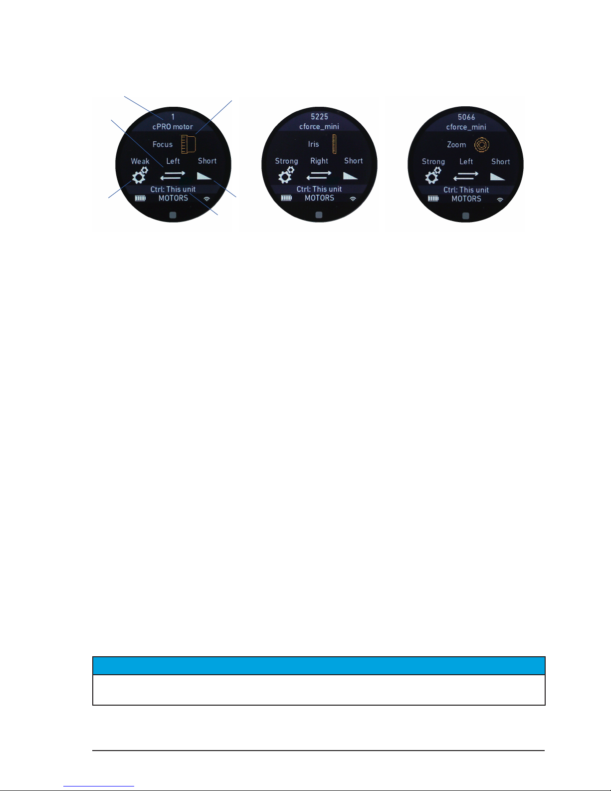
1 Knob (assigned axis)
2 Slider (assigned axis)
3 Joystick (assigned axis)
4 Pre-marked focus ring loaded (type)
5 Pre-marked iris strip loaded (type)
The controls main screen displays information about the control interfaces knob, slider
and joystick and their assigned axis, focus, iris and zoom. It also shows information about
loaded pre-marked focus rings and / or pre-marked iris strips.
Note: The controls adjustment menu can be accessed from the controls main screen quickly
by tapping and holding the touch display or by pressing and holding menu button 2 (MB2).
Controls main screen
Controls main screen with loaded
pre-marked focus ring / iris strip
3
1
2
4
5
Page 31
All content © 2018, cmotion GmbH. All specications are subject to change without further notice.
http://www.cmotion.eu
page 31 of 80
6.1.7. Motors main screens
1 Axis (Focus/Iris/Zoom)
2 Torque (Min/Weak/Strong/Max)
3 Direction (Left/Right)
4 Ramp (Min/Short/Long/Max)
5 Device in control (this unit / name, serial number)
6 LBUS device ID (serial number/name)
The motors main screens displays information for up to 3 daisy-chained cforce / cPRO
motors.
Axis: Displays information about the motor assigment to focus, iris or zoom.
Note: The axis menu only changes the assignment of the motor, not the assignemnt of the
control interface.
Torque: Displays information about the motor strength (Min/Weak/Strong/Max).
Direction: Displays information about the motor being mounted on the left or on the right
side of the camera.
Note: The direction is dened from the operators point of view, from behind the camera.
Ramp: Displays information about the start and stop acceleration of the motor (Min/
Short/Long/Max) which allows smooth speed-up and slow-down curves.
Ctrl: Displays information about the controlling device. If multiple hand units are used
and the highlighted motor is being controlled by a controller other than the one you are
viewing the menu on “this hand unit” Ctrl will display the name and serial number of the
hand unit which is controlling that motor.
NOTICE
The motor settings menu can be accessed from all motors main screens quickly by tapping
and holding the touch display or by pressing and holding menu button 2 (MB2).
1
2
4
5
5
3
Page 32
All content © 2018, cmotion GmbH. All specications are subject to change without further notice.
http://www.cmotion.eu
page 32 of 80
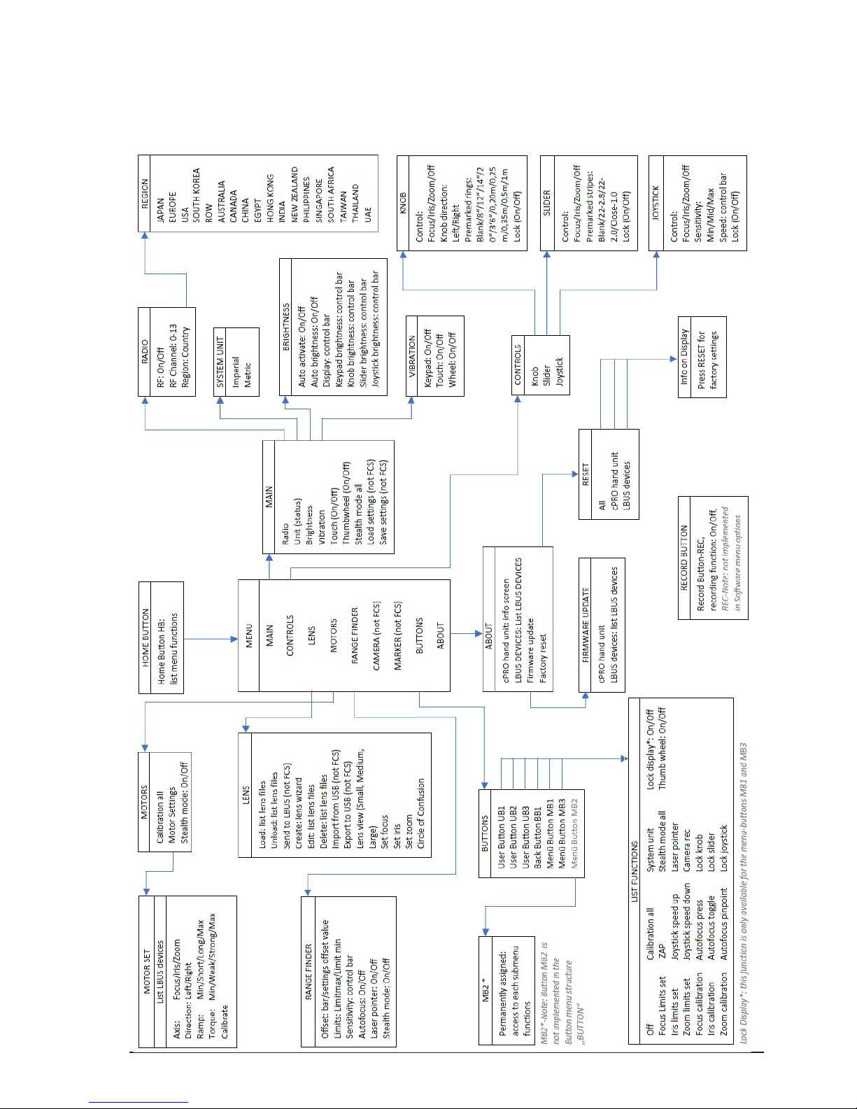
6.2. Adjustment menu
6.2.1. Adjustment menu overview
Page 33

All content © 2018, cmotion GmbH. All specications are subject to change without further notice.
http://www.cmotion.eu
page 33 of 80
6.2.2. Adjustment menu navigation
There are multiple ways to enter and navigate through the adjustment menu depending
on your preferences. If the touch screen is disabled or you are wearing gloves, all menu
pages can be accessed and settings changed using the thumb wheel and menu buttons.
NAVIGATION HOME button Touch screen Thumb wheel Buttons
enter the adjust-
ment menu
press short twice tap short twice
enter related ad-
justment menu
tap and hold press and hold
MB2 (QUICK
NAV)
leave the adjustment menu
press short swipe right (until
leave)
back (until leave)
navigate down swipe up turn counter-
clockwise
navigate up swipe down turn clockwise
enter sub menu
(select)
swipe left select
leave sub menu
(back)
swipe right back
increase values swipe up turn counter-
clockwise
decrease values swipe down turn clockwise
In the following text, every single sub menu will be explained with its corresponding
function. Some of the sub menus show the set status in their text, others do not.
6.2.3. Menu
The menu consists of the following sub menus:
MAIN
CONTROLS
LENS
MOTORS
RANGEFINDER
CAMERA*
MARKER**
BUTTONS
ABOUT
* License required for control of camera settings / available with Software Release Package
v2.0
** available with Software Release Package v2.0
Page 34

All content © 2018, cmotion GmbH. All specications are subject to change without further notice.
http://www.cmotion.eu
page 34 of 80
6.2.3.1. MAIN
The main menu includes all hand unit related settings which can be adjusted in the
corresponding sub menus. These include:
Radio
Unit (status)
Brightness
Vibration
Touch screen (status)
Thumb wheel (status)
Stealth mode all
Load settings*
Save settings*
* available with Software Release Package v2.0
6.2.3.1.1. Radio
The radio menu consits of the following RF related settings:
RF (status)
Channel (status)
Region (status)
6.2.3.1.1.1. RF
The RF menu allows you to turn the wireless radio on or o.
Note: If the cPRO hand unit is connected hard-wired to the cPRO motor or cPRO camin via
the daisy-chain, the system will detect an LBUS loop and will turn the radio o automatically
(LBUS loop detection). As soon as the cPRO hand unit is disconnected from the LBUS
daisy-chain, the radio will be turned on and return to it’s previous settings automatically.
6.2.3.1.1.2. Channel
The channel menu allows you to select one of the 14 radio channels from 0-13.
Note: In order to establish a wireless connection between the cPRO hand unit and the cPRO
motor / cPRO camin, both devices need to be set to the same RF channel. (How to select
the RF channel on the cPRO motor / cPRO camin, please refer to corresponding user guide)
6.2.3.1.1.3. Region
The region menu allows you to change the RF settings according to legal regulations
of the country / region, you are operating in. Changing the region settings on the cPRO
hand unit will automatically change the region settings on the connected cPRO motor /
cPRO camin if a wireless connection is established. The corresponding country code will
illuminate on the cPRO motor´s / cPRO camin´s display.
Note: Make sure that you select the proper area you are operating the device in. All available
region settings comply with Part 15 of the FCC rules.
Page 35
All content © 2018, cmotion GmbH. All specications are subject to change without further notice.
http://www.cmotion.eu
page 35 of 80
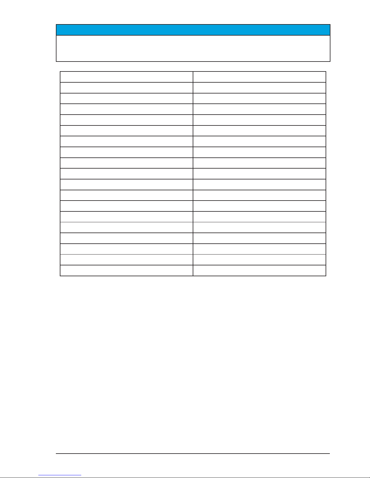
NOTICE
It may not be legal to operate the cPRO hand unit in a country/region other than the country/
region selected in the region menu. Select ROW (Rest of world) or use the device in hard-
wired mode if you are unsure of the correct region setting.
Region Setting Country code
Australia AU
Canada CA
China CN
Egypt EG
Europe EU
Hong Kong HK
India IN
Japan JP
New Zealand NZ
Philippines PH
Singapore SG
South Africa ZA
South Korea SG
Taiwan TW
Thailand TH
UAE (United Arab Emirates) AE
USA US
ROW (Rest of world) WORLD
6.2.3.1.2. Unit
The unit menu allows you to change the system unit to imperial or metric.
Note: Changing the system unit from the cPRO hand unit will change the unit settings on all
connected LBUS devices exept cameras connected through the CAM connector.
Page 36

All content © 2018, cmotion GmbH. All specications are subject to change without further notice.
http://www.cmotion.eu
page 36 of 80
6.2.3.1.3. Brightness
The brightness menu allows you to individually adjust the brightness level on several main
components of the cPRO hand unit. It also includes functions like auto brightness and
auto activate.
The brightness menu consits of the following functions:
Auto activate (status)
Auto brightness (status)
Display
Keypad brightness
Knob brightness
Slider brightness
Joystick brightness
6.2.3.1.3.1. Auto activate
The auto activate function can be turned on or o. If turned on, the cPRO hand unit´s
illumination will turn o if the light sensor is exposed to a light source. If it gets darker,
the illumination will switch on to the pre-dened brightness settings again (e.g if you
are shooting outside and you have to enter a dark building). If turned o, the previous
brightness settings will be activated.
6.2.3.1.3.2. Auto brightness
The auto brightness function can be turned on or o. If turned on, the cPRO hand unit´s
illumination will adjust dynamically to produce the best contrast for the environmental
lighting. If turned o, the previous brightness settings will be activated.
6.2.3.1.3.3. Display
The display menu allows you to adjust the brightness of the touch display individually.
Use the thumb wheel to turn the brightness up or down. Press select to conrm your
brightness settings.
6.2.3.1.3.4. Keypad brightness
The keypad brightness menu allows you to adjust the brightness of the all illuminated
buttons individually. Use the thumb wheel to turn the brightness up or down. Press select
to conrm your brightness settings.
6.2.3.1.3.5. Knob brightness
The knob brightness menu allows you to adjust the brightness of the focus ring illumination
individually. Use the thumb wheel to turn the brightness up or down. Press select to
conrm your brightness settings
Page 37
All content © 2018, cmotion GmbH. All specications are subject to change without further notice.
http://www.cmotion.eu
page 37 of 80
6.2.3.1.3.6. Slider brightness
The slider brightness menu allows you to adjust the brightness of the slider strip illumination
individually. Use the thumb wheel to turn the brightness up or down. Press select to
conrm your brightness settings
6.2.3.1.3.7. Joystick brightness
The joystick brightness menu allows you to adjust the brightness of the position indicator
display illumination individually. Use the thumb wheel to turn the brightness up or down.
Press select to conrm your brightness settings
6.2.3.1.4. Vibration
The vibration menu consits of the following functions:
Keypad (status)
Touch screen (status)
Thumb wheel (status)
6.2.3.1.4.1. Keypad
The keypad menu allows you to turn the tactile vibration feedback for all buttons on or o.
6.2.3.1.4.2. Touch screen
The touch screen menu allows you to turn the tactile vibration feedback for the touch
display on or o.
6.2.3.1.4.3. Thumb wheel
The thumb wheel menu allows you to turn the tactile vibration feedback for the thumb
wheel on or o.
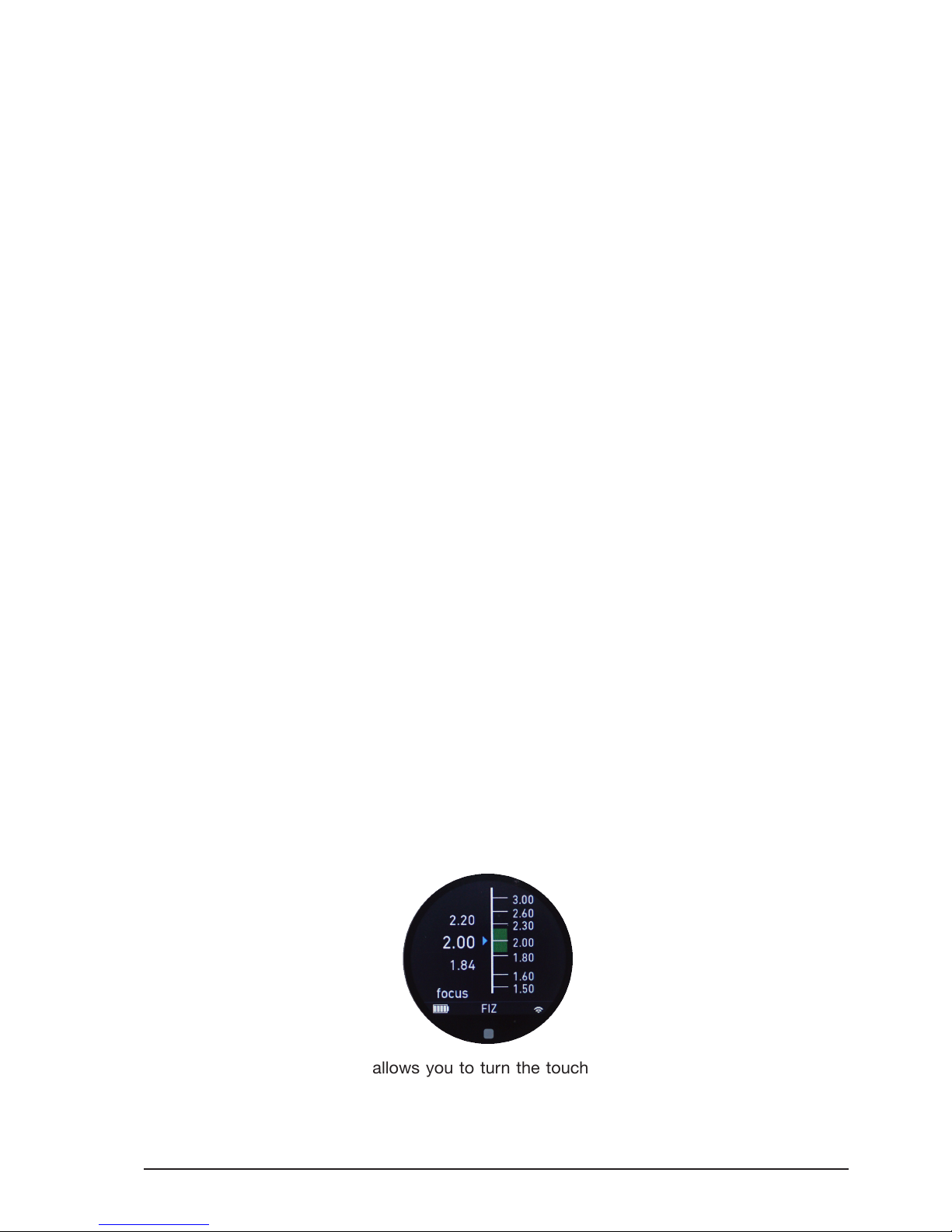
6.2.3.1.5. Touch screen
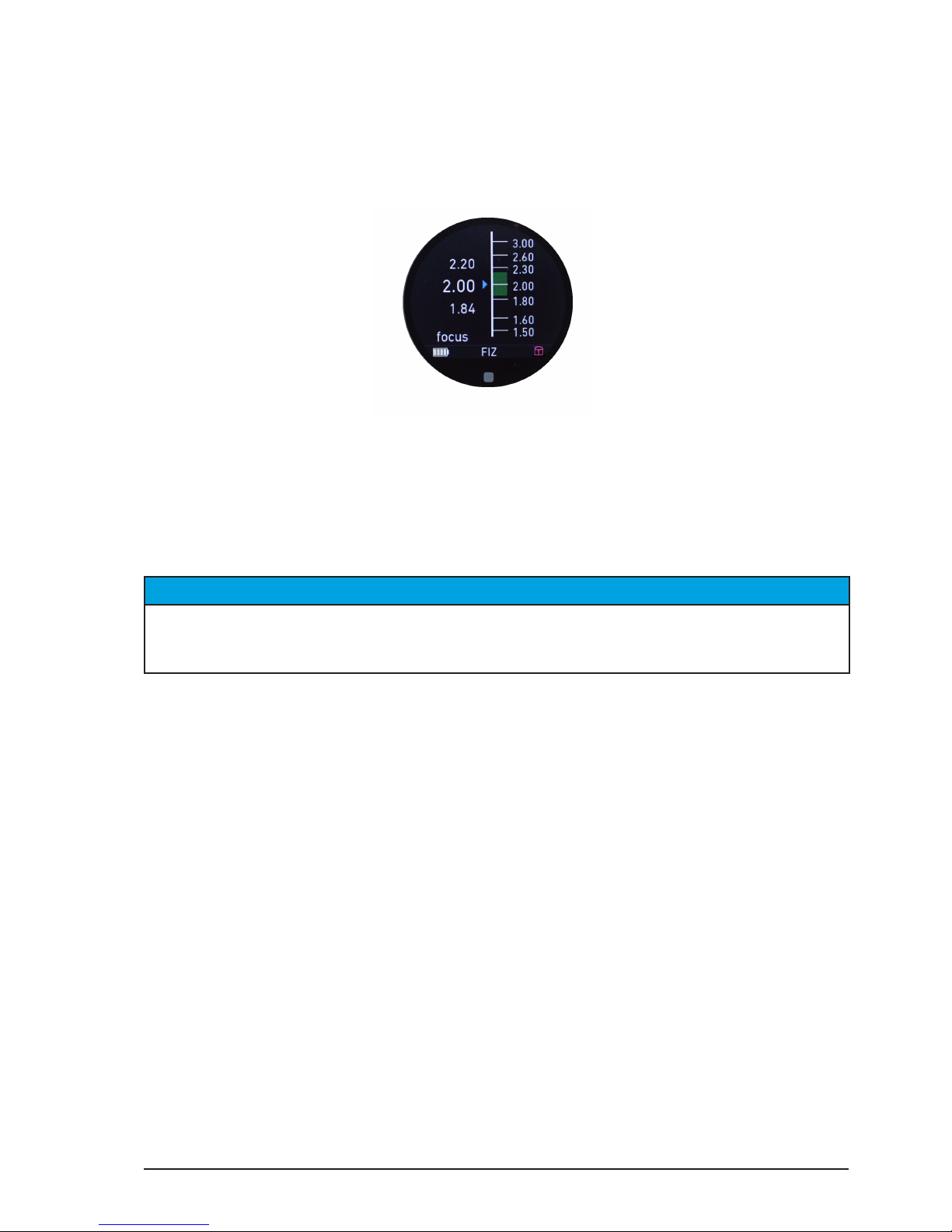
The touch screen menu allows you to turn the touch screen on (unlock) or o (lock). A
small red lock will be displayed in the status bar on all main screens. The letter “D” for
Display will illuminate each time you press the locked touch screen.
Page 38
All content © 2018, cmotion GmbH. All specications are subject to change without further notice.
http://www.cmotion.eu
page 38 of 80
Note: The touch screen will be locked for all main screen navigation only. Within the
adjustement menu, the touch screen will be unlocked automatically to allow smooth
navigation. In order to enter the adjustment menu, if the touch screen is locked, press the
home button twice.
6.2.3.1.6. Thumb wheel
The thumb wheel menu allows you to turn the thumb wheel on (unlock) or o (lock). A
small red lock will be displayed in the status bar on all main screens. The letter “T” for
thumb wheel will illuminate each time you turn the thumb wheel.
Note: The thumb wheel will be locked for main screen navigation only. Within the adjustment
menu, the thumb wheel will be unlocked automatically to allow smooth navigation. In order
to enter the adjustment menu, if the touch screen is locked, press the home button twice.
NOTICE
If the thumb wheel and the touch screen is o (locked) at the same time, a navigation through
the main screens is not possible anymore. In order to enter the adjustment menu, press the
home button twice and unlock the control interfaces if needed.
6.2.3.1.7. Stealth mode all
The stealth mode all menu allows to turn the stealth mode on or o for all LBUS devices
in the daisy-chain. If stealth mode is on, all LBUS devices on the camera side´s daisychain will turn their illumination o (e.g. if the camera angle is critical because of camera
reection in the picture).
6.2.3.2. CONTROLS
The controls menu contains all settings related to the main controls: knob, slider and
joystick.
Knob
Slider
Joystick
Page 39

All content © 2018, cmotion GmbH. All specications are subject to change without further notice.
http://www.cmotion.eu
page 39 of 80
6.2.3.2.1. Knob
The knob menu contains all settings related to the knob control interface and consists of:
Control (status)
Knob direction (status)
Pre-marked rings
Lock (status)
6.2.3.2.1.1. Control
The control menu allows you to assign the axis you want to control (Focus / Iris / Zoom)
to the knob. If you select O, the knob will have no control over any axis and will turn its
marker ring illumination and status LEDs o.
6.2.3.2.1.2. Knob direction
The knob direction menu allows you to change the knob direction from left to right. Left
means that innity is on the end stop turning the knob clockwise. Right means that innity
is on the end stop turning the knob counter-clockwise.
Note: Knob direction can be adjusted with individually marked focus rings only. With premarked focus rings the knob direction is always right / counter-clockwise.
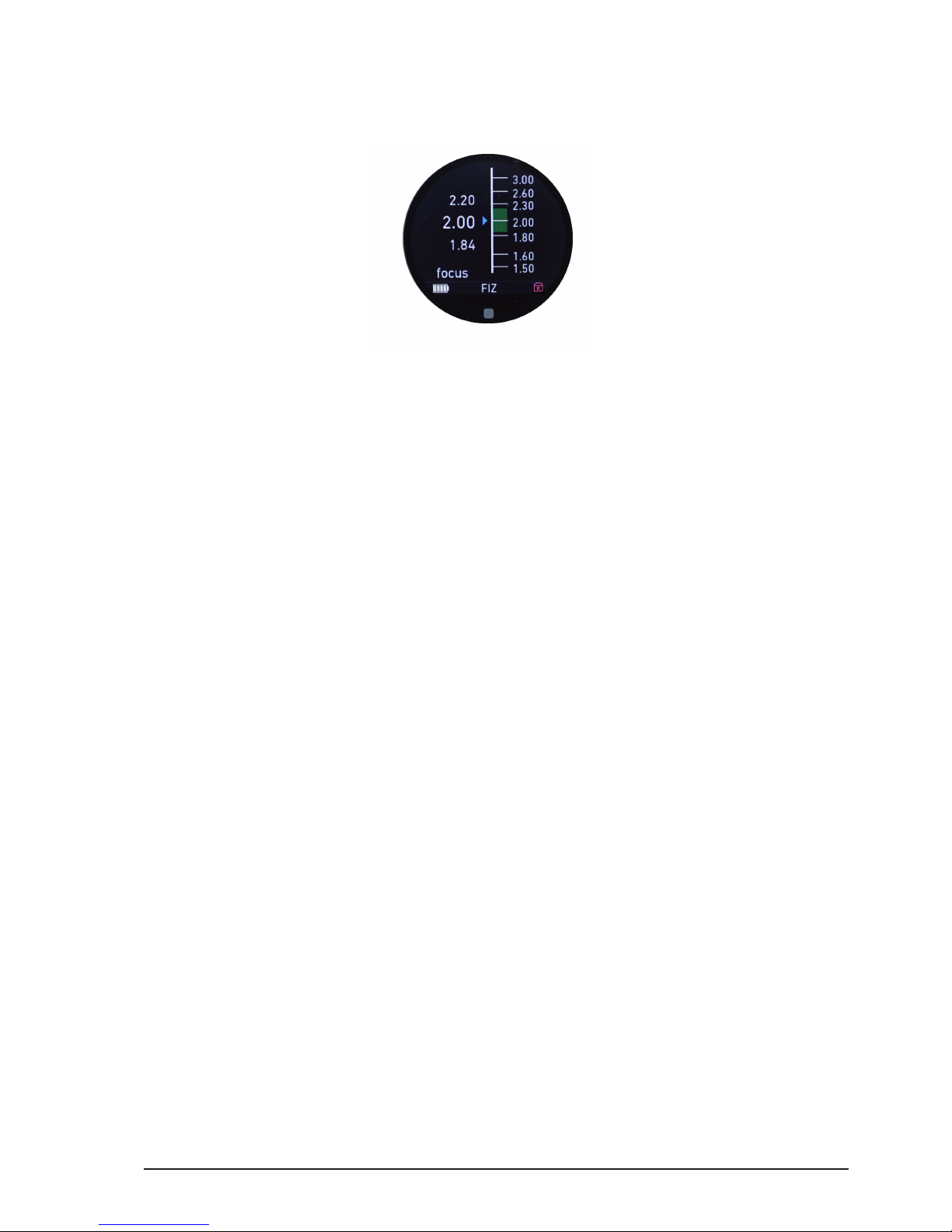
6.2.3.2.1.3. Pre-marked rings
The pre-marked rings menu allows you to select one of ve imperial and ve metric pre-
marked focus rings. Each ring is engraved with a scale from innity to one of ve close
focus values. Pre-marked focus rings can be used with a wide range of lenses from wide
angle to telelphoto and save time marking a focus marker ring for each lens.
Pre-marked focus rings are available in imperial or metric scales:
8” 0,20m
12” 0,25m
14” 0,35m
20” 0,5m
3´6” 1m
Note: Before pre-marked focus rings can be used, a lens le needs to be created using the
cPRO hand unit´s internal ‘create lens’ feature or a cworld.
In order to use a pre-marked focus rings please proceed as follows:
■ Calibrate the lens
■ Load the corresponding lens le from the cPRO hand unit or cworld
■ Choose the right pre-marked focus ring to match the close focus value of your
lens.
■ Enter the pre-marked rings menu and select the appropriate marker ring from the
list
Page 40
All content © 2018, cmotion GmbH. All specications are subject to change without further notice.
http://www.cmotion.eu
page 40 of 80
6.2.3.2.1.4. Lock
The lock menu allows you to lock the knob (e.g. if shooting with a locked o camera).
A small red lock will be displayed in the status bar on all main screens. The letter “K” for
knob will illuminate each time you turn the knob. The knob illumination will start ashing
red, indicating that the knob is locked and no motor control is possible.
6.2.3.2.2. Slider
The slider menu contains all settings related to the slider control interface and consists of:
Control (status)
Pre-marked strips
Lock (status)
6.2.3.2.2.1. Control
The control menu allows you to assign the axis you want to control (Focus / Iris / Zoom)
to the slider. If you select O, the slider will have no control over any axis and will turn its
marker strip illumination and status LEDs o.
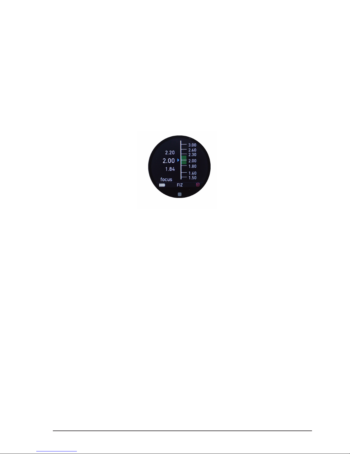
6.2.3.2.2.2. Pre-marked strips
The pre-marked strips menu allows you to select one of three pre-marked iris strips. Each
strip is engraved with a scale from close or 22 to one of 3 open iris values. Pre-marked
iris strips can be used with a wide range of lenses and save time marking an iris strip for
each lens.
Pre-marked iris strips are available with the following T-stop scales:
close - 1.0
22 - 2.0
22 - 2.8
Note: Before pre-marked iris strips can be used, a lens le needs to be created using the
cPRO hand unit´s internal ‘create lens’ feature or a cworld.
Page 41
All content © 2018, cmotion GmbH. All specications are subject to change without further notice.
http://www.cmotion.eu
page 41 of 80
In order to use a pre-marked iris strips please proceed as follows:
■ Calibrate the lens motors
■ Load the corresponding lens le from the cPRO hand unit or cworld
■ Choose the right pre-marked iris strip to match the open iris value of your lens.
■ Enter the pre-marked strips menu and select the appropriate marker strip from the
list
6.2.3.2.2.3. Lock
The lock menu allows you to lock the slider (e.g. if shooting with a locked o camera).
A small red lock will be displayed in the status bar on all main screens. The letter “S” for
slider will illuminate each time you turn the knob. The slider illumination will start ashing
red, indicating that the slider is locked and no motor control is possible.
6.2.3.2.3. Joystick
The joystick menu contains all settings related to the joystick control interface and consists
of:
Control (status)
Sensitivity
Speed
Lock (status)
6.2.3.2.3.1. Control
The control menu allows you to assign the axis you want to control (Focus / Iris / Zoom) to
the joystick. If you select O, the joystick will have no control over any axis and will turn
the illuminated position inticator o.
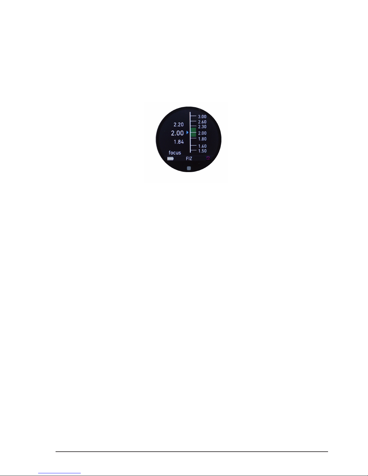
6.2.3.2.3.2. Sensitivity
The sensitivity menu allows you to adjust the touch sensitivity of the micro-force joystick
to Min, Mid or Max. At Min, the joystick needs more preasure to react. At Max, the joystick
will respond to a lighter touch.
Page 42
All content © 2018, cmotion GmbH. All specications are subject to change without further notice.
http://www.cmotion.eu
page 42 of 80
6.2.3.2.3.3. Speed
The speed menu allows you to adjust the motor speed of the joystick´s assigned axis. Use
the thumb wheel to increase or decrease the motor speed. Press select to conrm your
speed settings.
6.2.3.2.3.4. Lock
The lock menu allows you to lock the joystick (e.g. if shooting with a locked o camera).
A small red lock will be displayed in the status bar on all main screens. The letter “J” for
joystick will illuminate each time you touch the joystick. The status LED of the joystick will
start ashing red, indicating that the joystick is locked and no motor control is possible.
6.2.3.3. LENS
The lens menu contains all settings related to lens les and lens le handling and consists
of:
Load
Unload
Create
Edit
Delete
Lens View
Set iris
Set zoom
Circle of confusion
Note: A lens le must be loaded on the hand unit to view and use cPRO’s advanced features.
These include, lens data, pre-marked rings and sliders, and autofocus. Lens data can be
created on the cPRO hand hand unit using the internal create lens wizard or cworld. It is
also possible to upload archive lens les via the USB port (available with Software Release
Package v2.0).
Page 43
All content © 2018, cmotion GmbH. All specications are subject to change without further notice.
http://www.cmotion.eu
page 43 of 80
6.2.3.3.1. Load
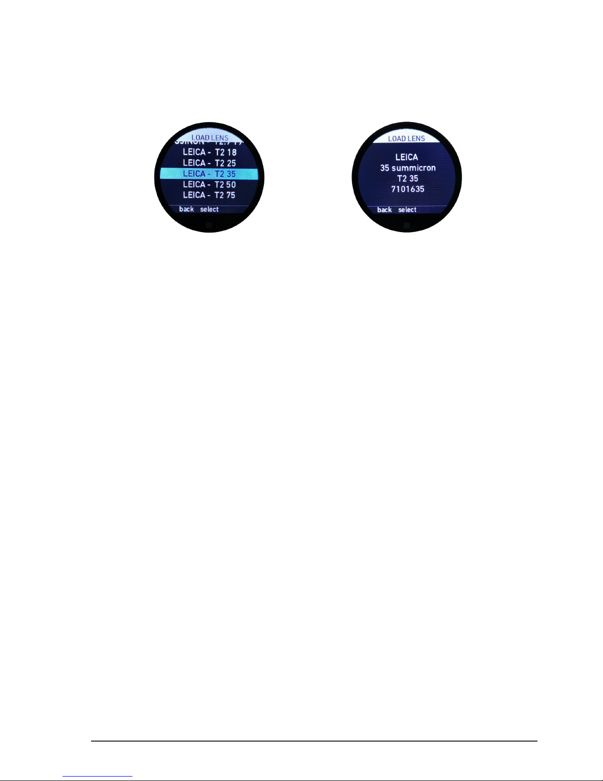
The load menu allows you to load a lens le from the list of lens les stored in the cPRO
hand unit’s internal memory. Up to 30 lens les can be stored internally.
If you select a lens le form the list by pressing select, detailed lens le information will
show up on the following screen. If you press select again or make a short tap on the
touch screen, the lens le will be loaded without further conrmation required. If you want
to choose a dierent lens le than the one shown in the details screen, simply press back
or swipe right to return to the lens le list.
6.2.3.3.2. Unload
The unload menu allows you to unload an already loaded lens le. Selecting unload will
unload the lens le without further conrmation required.
Note: If there is no lens loaded on the hand unit, advanced cPRO features will be disabled
and the main screen will only display a percentage of th motors calibrated range.
Page 44
All content © 2018, cmotion GmbH. All specications are subject to change without further notice.
http://www.cmotion.eu
page 44 of 80
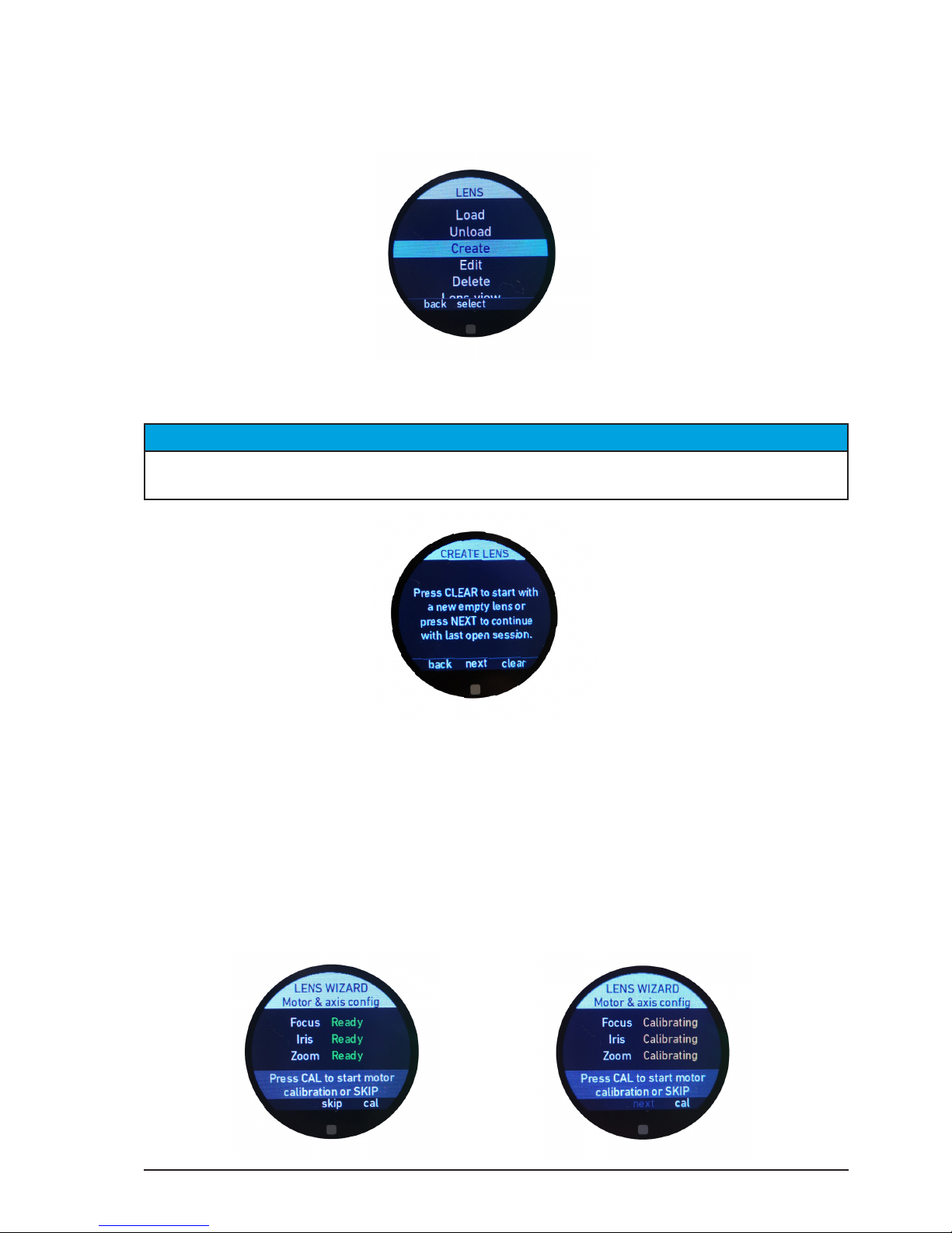
6.2.3.3.3. Create
The Create menu allows you to create a lens le using the cPRO hand unit’s internal lens
wizard. To create a new lens le, follow the procedure below.
Note: While creating a new lens le, it is possible to exit the lens wizard using the back
function (MB1) or the HOME button at any stage without loosing recently entered data.
NOTICE
Please make sure the motor is correctly assigned to the right or left side of the camera. Please
refer to section “6.2.3.4.2.3. Direction” on page 56 in this manual.
Once you re-enter the lens wizard, you can select whether you want to create a new lens
or continue with the lens from the previous session. Press “clear” (MB3) if you want to
delete all data from the previous session and start creating a new lens. Press “next” (MB2)
if you want to keep the data from the previous session and continue creating data for that
lens. Press “back” (MB1) to return to the previous menu page.
6.2.3.3.3.1. Motor calibration
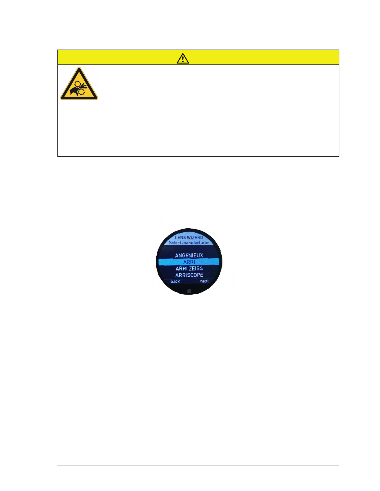
Please ensure ALL motors are fully calibrated. If they are already, you can press “skip”
(MB2).
Page 45
All content © 2018, cmotion GmbH. All specications are subject to change without further notice.
http://www.cmotion.eu
page 45 of 80
If you are not sure press “cal” (MB3) to start motor calibration. Once the motors have
been calibrated properly press “next” (MB2.)
CAUTION!
Risk of injury! Do not touch the motor gear while motor is powered up!
This device is not intended for use by children. Keep body parts out of the motion path.
Disconnect the plug if the device is not used for a longer period of time.
IEC 60417-6056 (2011-05) for other moving parts
6.2.3.3.3.2. Select manufacturer
Select the name of the lens manufacturer from the list of brands. Scroll through the list
using the thumb wheel or swipe up or down using the touch screen.
Conrm your selection by pressing “next” (MB3) or swipe left on the touch screen.
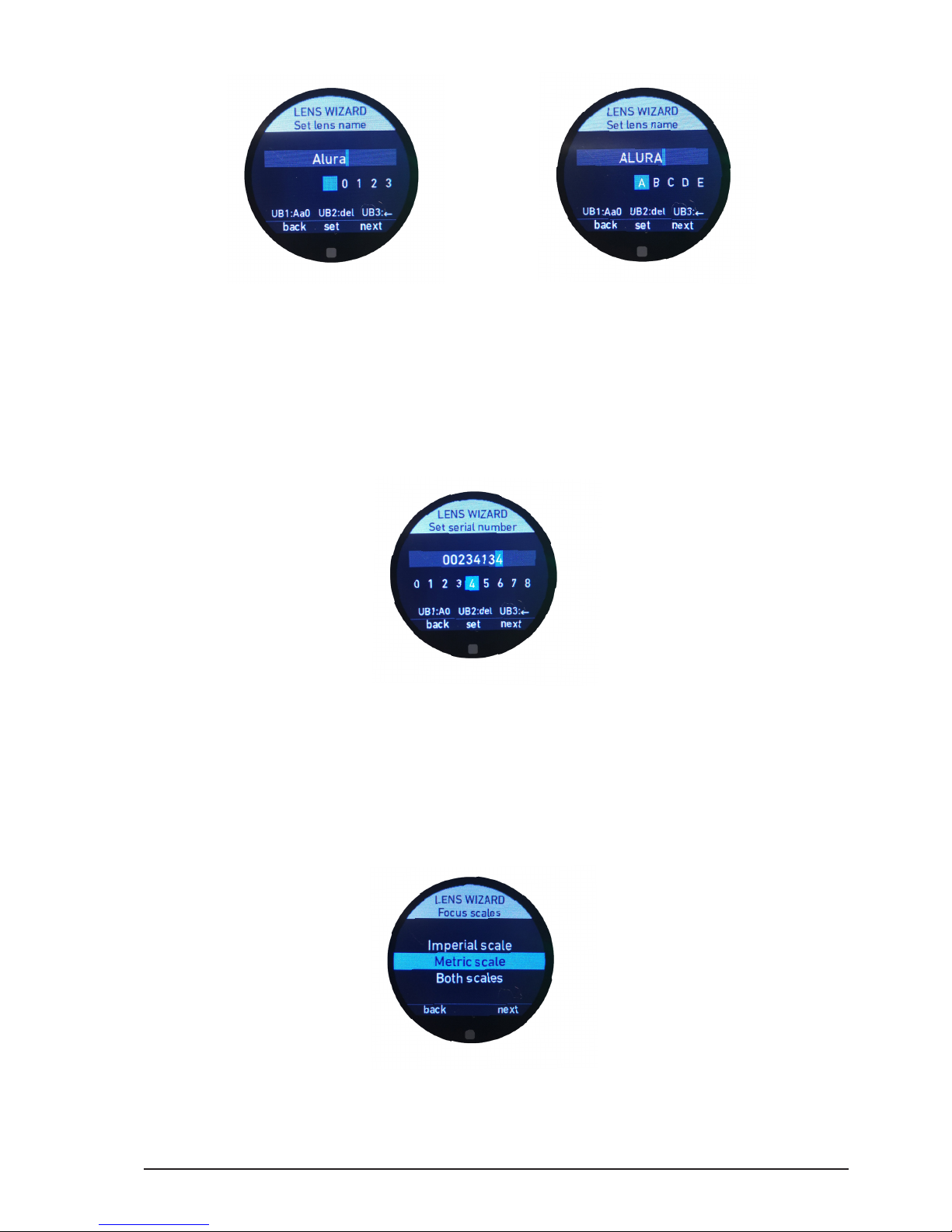
6.2.3.3.3.3. Set lens name
To create the lens name, scroll through the alphabetic characters using the thumb wheel
or swipe up or down on the touch screen. A minimum of two characters are required to
create and save a lens name.
Once the desired letter is highlighted in blue, press “select” (MB2) to set the character. As
an alternative, you can also tap the touch screen to conrm your selection.
UB1 allows you to change between UPER CASE, lower case and numbers.
UB2 allows you to delete the last set character.
UB3 allows you to select a previous set character. Once it is highlighted in blue, you can
change it using the thumb wheel or touch screen or delete it by pressing UB2.
Page 46
All content © 2018, cmotion GmbH. All specications are subject to change without further notice.
http://www.cmotion.eu
page 46 of 80
Note: You can use a maximum of 18 characters to create a lens name.
Once you have completed the lens name, press “next” (MB3) to continue or swipe left on
the touch screen.
6.2.3.3.3.4. Set serial number
To help identify individual lens les, please enter the unique lens serial number. A minimum
of two characters are required to set and save a serial number.
Note: You are allowed to enter a maximum of 16 characters.
Conrm your selection by pressing “next” (MB3) or swipe left on the touch screen.
6.2.3.3.3.5. Focus imperial / metric selection
Lenses are usually engraved with either a metric or imperial focus scale. Please select
here if you want to create a metric scale, an imperial scale, or a scale for both imperial
and metric.
Note: In the following example, a metric scale is being created. However, please follow the
same procedure for creating an imperial scale or both scales.
Conrm your selection by pressing “next” (MB3) or swipe left on the touch screen.
Page 47
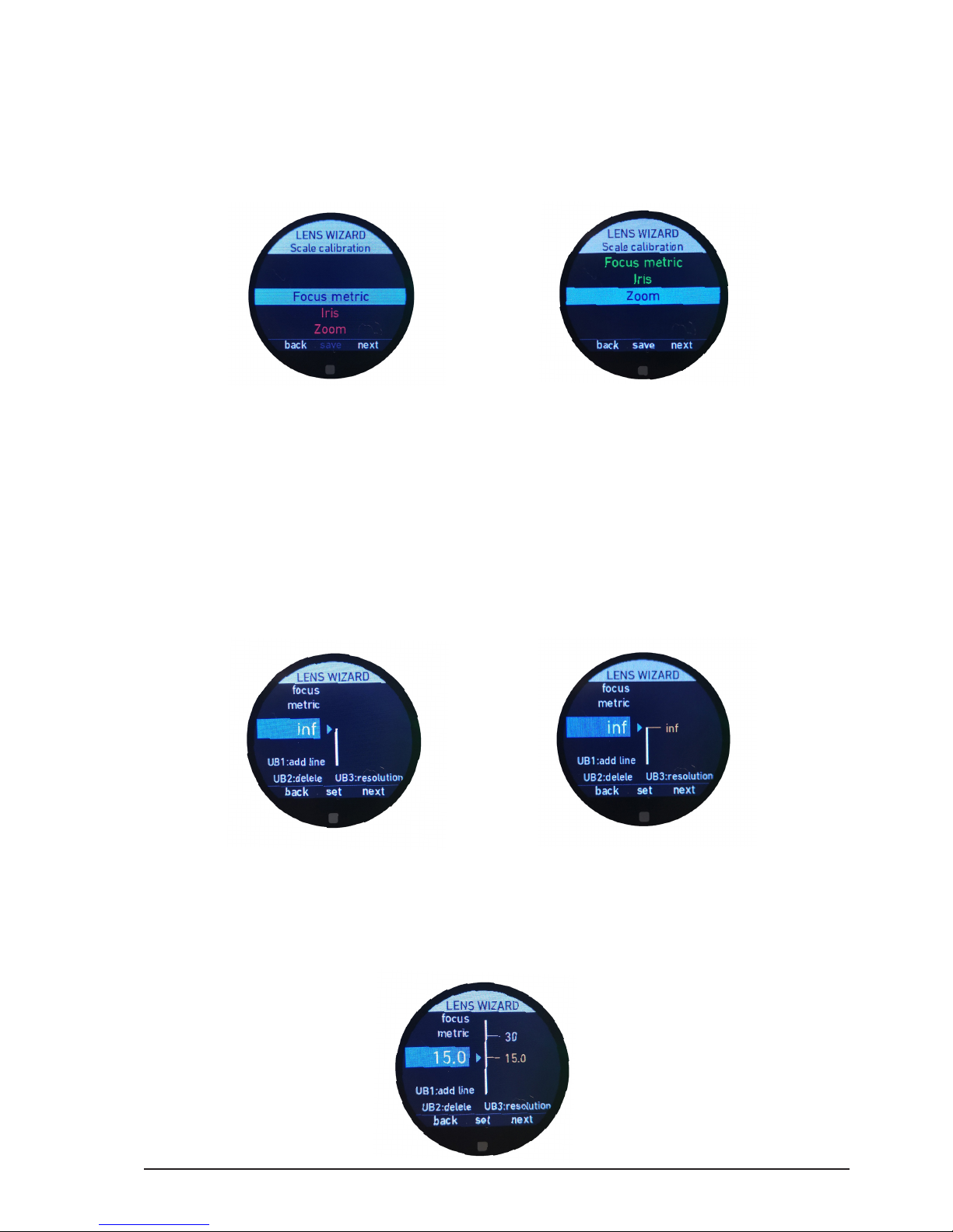
All content © 2018, cmotion GmbH. All specications are subject to change without further notice.
http://www.cmotion.eu
page 47 of 80
6.2.3.3.3.6. Scale calibration
The scale calibration menu allows you to select which scale you want to create. I.e. Focus,
Iris or Zoom. Initially, all scales will be illuminated in red and the “save” function (MB2)
will be grayed out. The scales will only illuminate green after assigning at least one value
for each scale. It is only possible to save the lens le when each axis (with an assigned
motor) is green.
Note: If you do not have a motor connected and assigned to iris and zoom, you must enter
at least one value for each corresponding scale. Please enter the open iris value for the iris
scale and the focal length of your prime lens in the zoom scale.
6.2.3.3.3.7. Focus scale
In general, you can start creating the focus scale from either direction. In this example
however, the lens is being created from innity to close focus.
Move the control interface assigned to focus (knob as default) until the datum line on your
lens matches innity.
Use the thumb wheel to scroll clockwise or counter-clockwise until you see “inf” in the
blue input box. As an alternative, you can also swipe the touch screen up or down.
Once “inf” is highlighted in the blue input box, press “set” (MB2) and the innity mark will
be set on the gracal scale bar. As an alternative, you can also tap the touch screen to
conrm your selection or press the back button (BB1).
Page 48
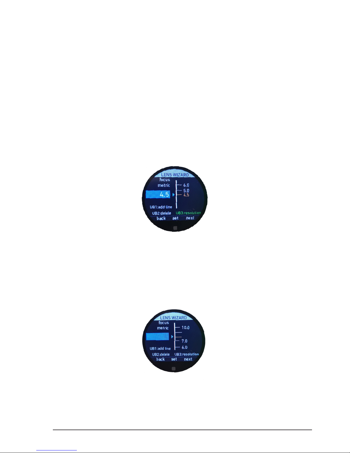
All content © 2018, cmotion GmbH. All specications are subject to change without further notice.
http://www.cmotion.eu
page 48 of 80
Move the control interface assigned to focus (knob as default) to the next line and value
on your lens.
If you move the lens from the last set value in one direction (in this case down, towards
close focus), the lens wizard will predict the next value.
If the predicted value is not a value marked on your lens, use the thumb wheel to scroll
clockwise or counter-clockwise until you see the desired value in the blue input box. As
an alternative, you can also swipe the touch screen up or down.
Once the desired value is highlighted in the blue input box, press “set” (MB2) and the
value mark will be set on the gracal scale bar. As an alternative, you can also tap the
touch screen to conrm your selection or press the back button (BB1).
Continue this procedure until you have set all important values on your lens.
Note: It is not necessary to assign every single lens value because the cPRO system will
predict missing values automatically. However, to achieve the best matching lens data, it is
recommended to input and assign as many values as possible using this procedure.
If a lens value is not displayed in the predicted list, press UB3 to change the resolution of
the input box. This allows you to enter any value. The text “UB3:resolution” will illuminate
green while the high resolution remains active. Press UB3 again to return to the original
resolution.
As long as a value is highlighted in yellow, you can delete it by pressing UB2. You can also
reposition the mark by moving lens to the new position and pressing “set” (MB2), tapping
the touch screen or pressing the back button (BB1).
UB1 allows you to set lines (without a value) in order to create a perfect animated depiction
of your lens. Lines can either be added between values or added separately after all the
values have been created.
Page 49
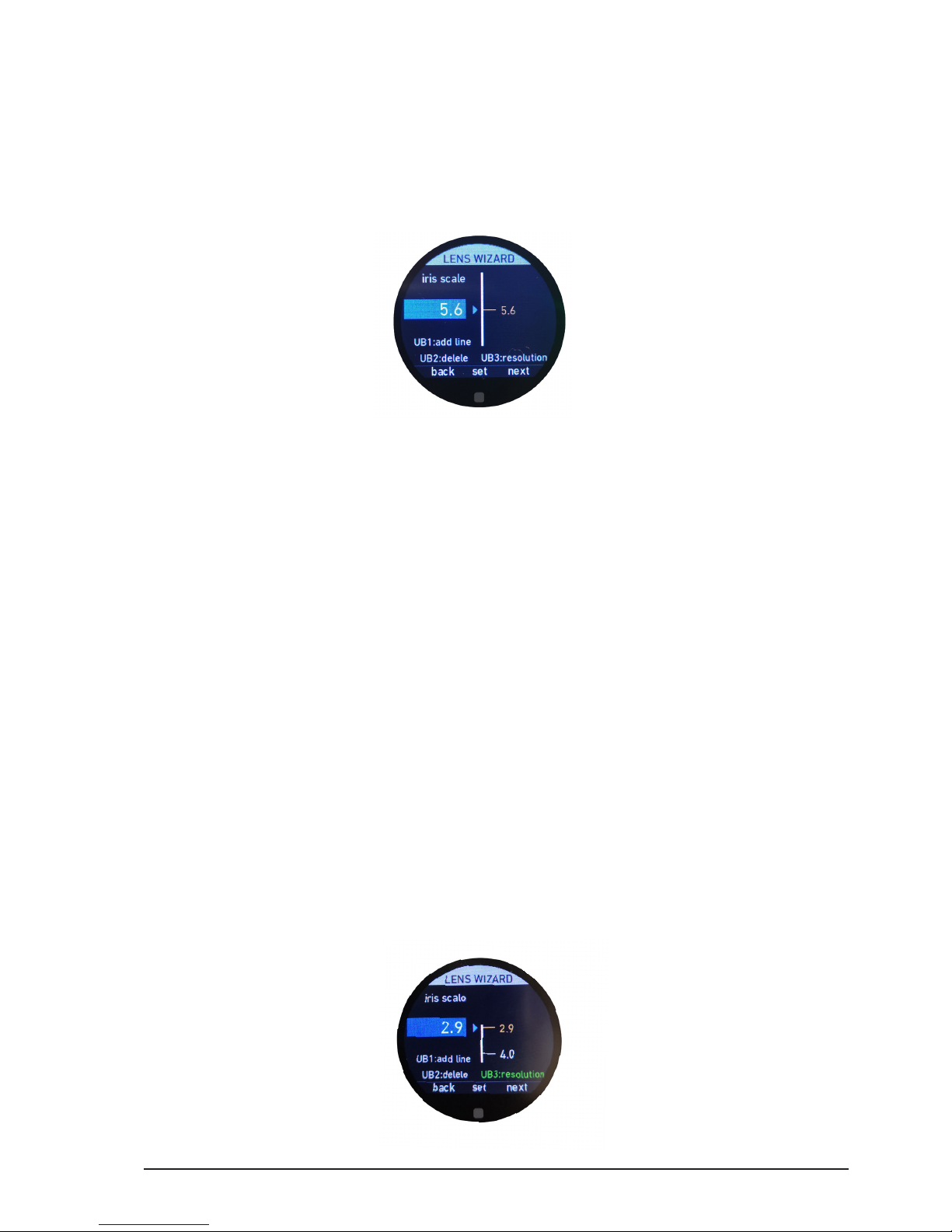
All content © 2018, cmotion GmbH. All specications are subject to change without further notice.
http://www.cmotion.eu
page 49 of 80
6.2.3.3.3.8. Iris scale
In general, you can start creating the iris scale from either open or closed.
Note: If you are not using an iris motor, please enter the wide open iris value of your lens.
Move the control interface assigned to iris (slider as default) until the datum line on your
lens matches the desired T-stop value.
Use the thumb wheel to scroll clockwise or counter-clockwise until you see the
corresponding numeric value in the blue input box. As an alternative, you can also swipe
the touch screen up or down.
Once the desired value is highlighted in the blue input box, press “set” (MB2) and the
value mark will be set on the gracal scale bar. As an alternative, you can also tap the
touch screen to conrm your selection or press the back button (BB1).
Move the control interface to the next line and value on your lens.
If you move the lens from the last set value in one direction, the lens wizard will predict
the next value.
If the predicted value is not a value marked on your lens, use the thumb wheel to scroll
clockwise or counter-clockwise until you see the desired value in the blue input box. As
an alternative, you can also swipe the touch screen up or down.
Once the desired value is highlighted in the blue input box, press “set” (MB2) and the
value mark will be set on the gracal scale bar. As an alternative, you can also tap the
touch screen to conrm your selection or press the back button (BB1).
Continue this procedure until you have set all important values on your lens.
Note: It is not necessary to assign every single lens value because the cPRO system will
predict missing values automatically. However, to achieve the best matching lens data, it is
recommended to input and assign as many values as possible using this procedure.
Page 50
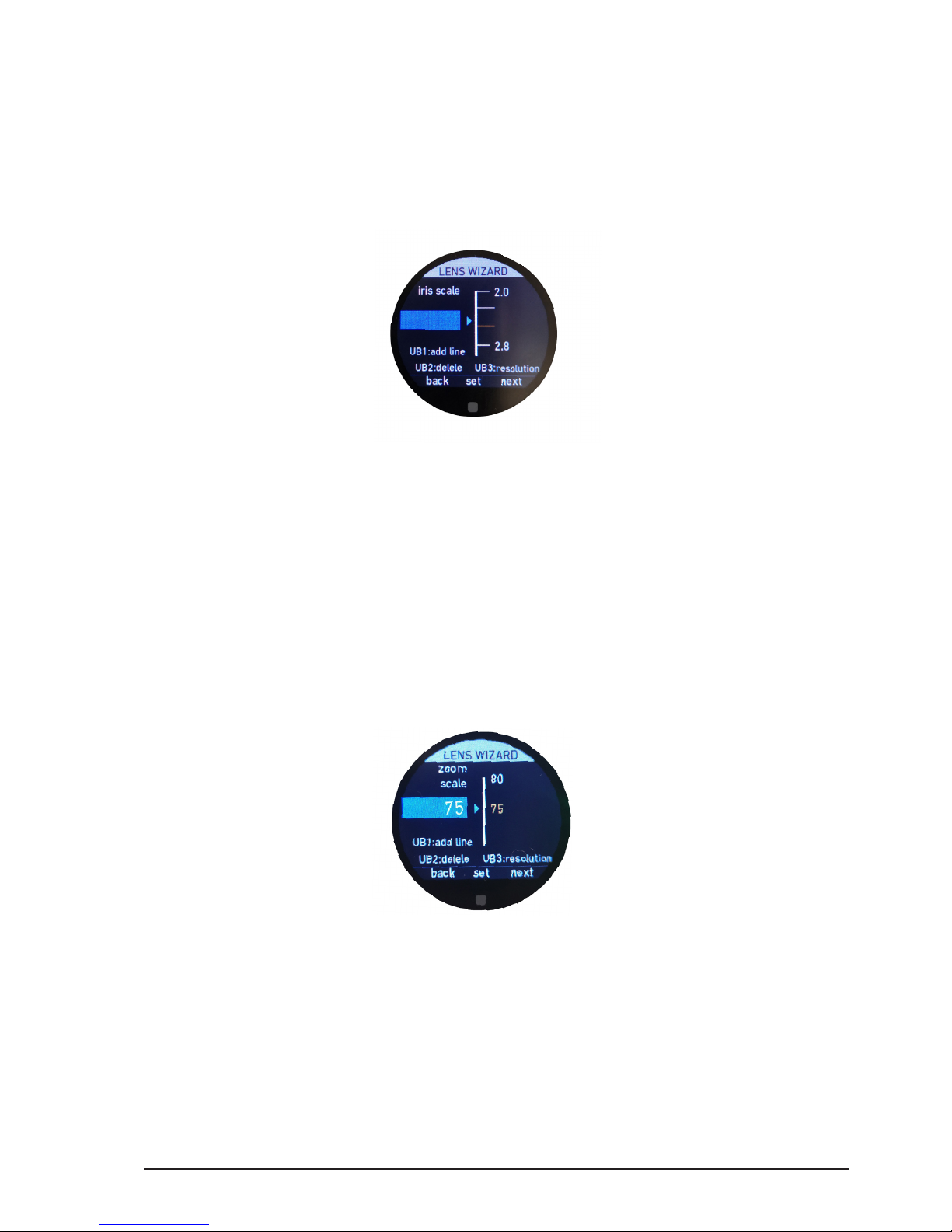
All content © 2018, cmotion GmbH. All specications are subject to change without further notice.
http://www.cmotion.eu
page 50 of 80
If a lens value is not displayed in the predicted list, press UB3 to change the resolution of
the input box. This allows you to enter any value. The text “UB3:resolution” will illuminate
green while the high resolution remains active. Press UB3 again to return to the original
resolution.
As long as a value is highlighted in yellow, you can delete it by pressing UB2. You can also
reposition the mark by moving lens to the new position and pressing “set” (MB2), tapping
the touch screen or pressing the back button (BB1).
UB1 allows you to set lines (without a value) in order to create a perfect animated depiction
of your lens. Lines can either be added between values or added separately after all the
values have been created.
6.2.3.3.3.9. Zoom scale
In general, you can start creating the zoom scale from either the long end or wide end of
the lens.
Note: If you are using a prime lens, please enter the focal length.
Move the control interface assigned to zoom (joystick as default) until the datum line on
your lens matches the desired focal length.
Use the thumb wheel to scroll clockwise or counter-clockwise until you see the
corresponding numeric value in the blue input box. As an alternative, you can also swipe
the touch screen up or down.
Once the desired value is highlighted in the blue input box, press “set” (MB2) and the
value mark will be set on the gracal scale bar. As an alternative, you can also tap the
touch screen to conrm your selection or press the back button (BB1).
Move the control interface to the next value on your lens.
If you move the lens from the last set value in one direction, the lens wizard will predict
the next value.
Page 51
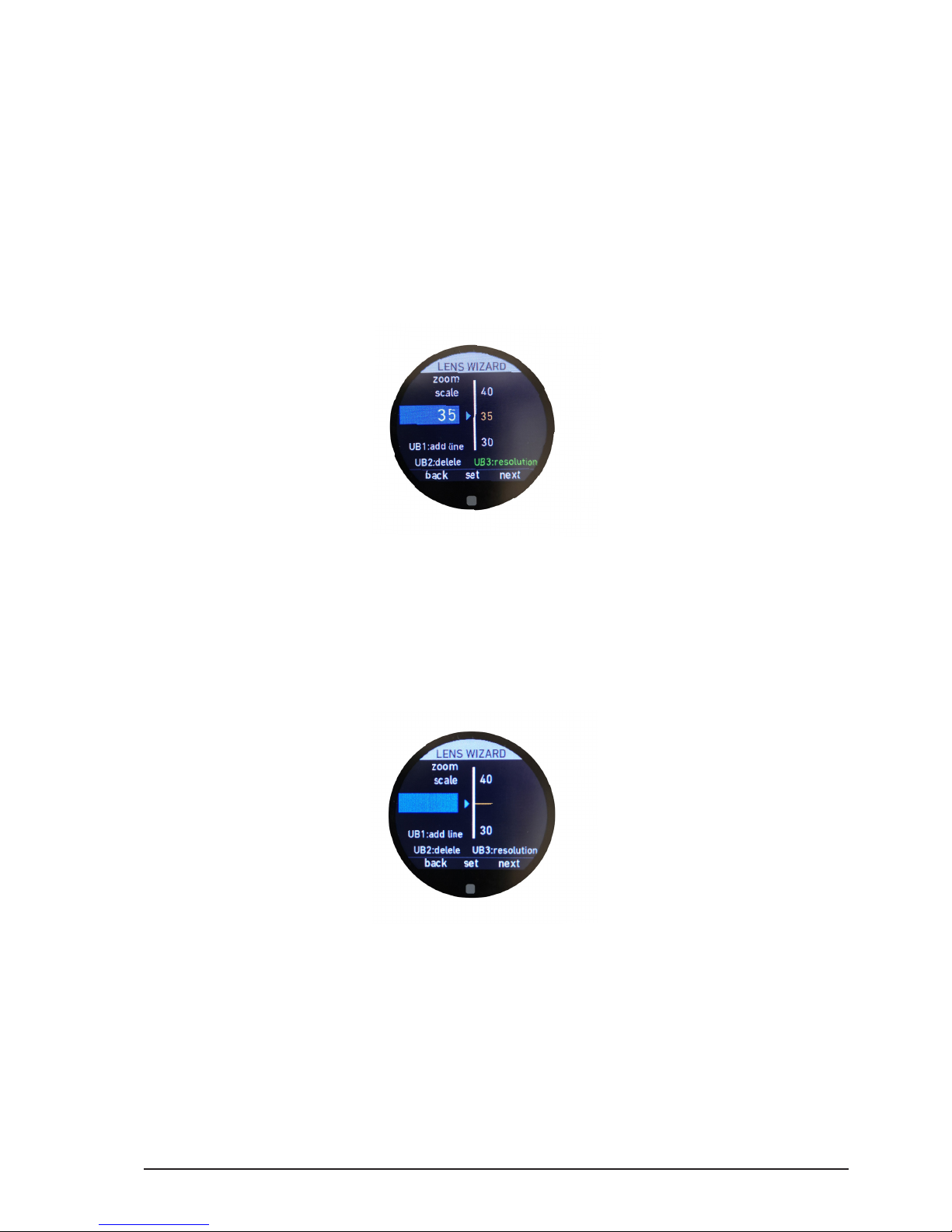
All content © 2018, cmotion GmbH. All specications are subject to change without further notice.
http://www.cmotion.eu
page 51 of 80
If the predicted value is not a value marked on your lens, use the thumb wheel to scroll
clockwise or counter-clockwise until you see the desired value in the blue input box. As
an alternative, you can also swipe the touch screen up or down.
Once the desired value is highlighted in the blue input box, press “set” (MB2) and the
value mark will be set on the gracal scale bar. As an alternative, you can also tap the
touch screen to conrm your selection or press the back button (BB1).
Continue this procedure until you have set all important values on your lens.
Note: It is not necessary to assign every single lens value because the cPRO system will
predict missing values automatically. However, to achieve the best matching lens data, it is
recommended to input and assign as many values as possible using this procedure.
If a lens value is not displayed in the predicted list, press UB3 to change the resolution of
the input box. This allows you to enter any value. The text “UB3:resolution” will illuminate
green while the high resolution remains active. Press UB3 again to return to the original
resolution.
As long as a value is highlighted in yellow, you can delete it by pressing UB2. But you can
also reposition the mark by moving the lens to the new position and pressing “set” (MB2),
tapping the touch screen or pressing the back button (BB1).
UB1 allows you to set lines (without a value) in order to create a perfect animated depiction
of your lens. Lines can either be added between values or added separately after all the
values have been created.
Page 52
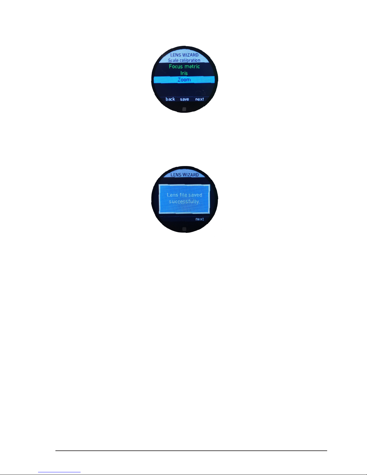
All content © 2018, cmotion GmbH. All specications are subject to change without further notice.
http://www.cmotion.eu
page 52 of 80
6.2.3.3.3.10. Save
As soon as at least one value is set per scale, the “save” icon will illuminate white. Press
MB2 to save the lens le to the internal memory of the cPRO hand unit. With the present
rmware release, up to 30 lens les can be saved.
Please close the lens wizard by pressing “next” (MB3) and return to the main menu.
Page 53
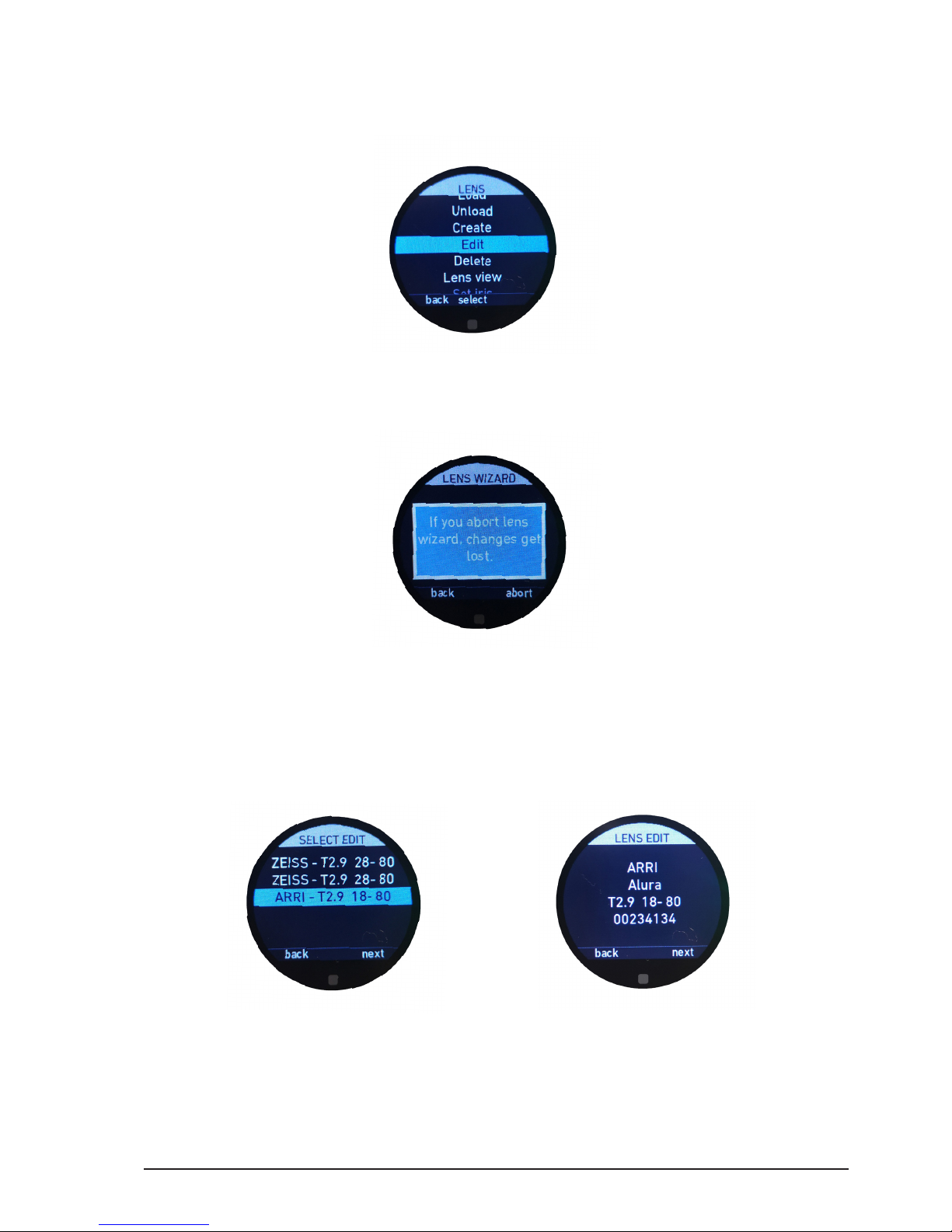
All content © 2018, cmotion GmbH. All specications are subject to change without further notice.
http://www.cmotion.eu
page 53 of 80
6.2.3.3.4. Edit
The edit menu allows you to edit existing lens les on the cPRO hand unit using the lens
wizard.
Note: If you are editing a lens le and you leave the lens wizard by pressing the back function
(MB1) or the HOME button, changes will not be saved. The following warning message will
be displayed.
You can then conrm whether you do want to leave the lens wizard by pressing “abort”
(MB3), or return to the lens wizard by pressing “back” (MB1).
The “edit lens” feature follows the exact same procedure as the “create lens” function
with the exeption, that you have to select the lens le you want to edit from the dynamic
list.
Press “next” (MB3) to select the lens le you want to edit. Press “back” (MB1) if you want
to select a dierent lens le.
Page 54
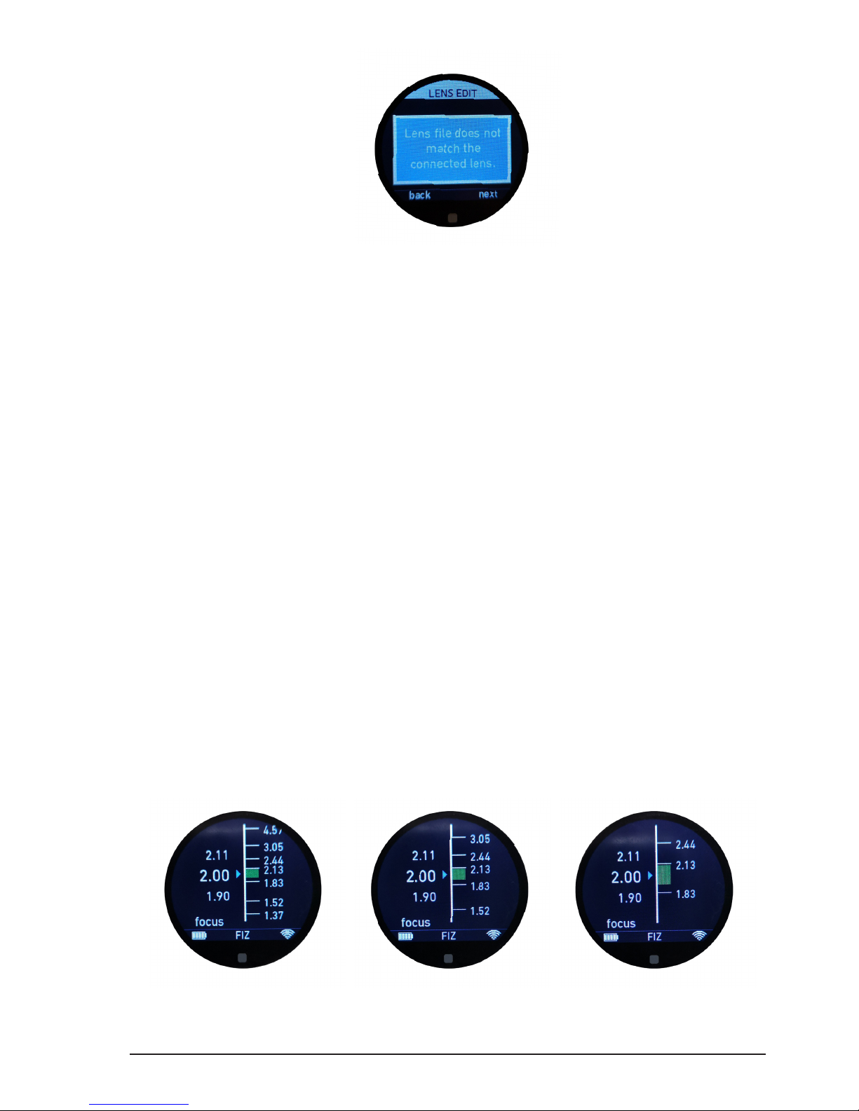
All content © 2018, cmotion GmbH. All specications are subject to change without further notice.
http://www.cmotion.eu
page 54 of 80
If the lens le you have selected does not match the motor calibration range, or e.g.
you select a prime lens and 3 motors connected, or a zoom lens with only one motor
connected, a warning message will appear. Press “next” (MB3) to continue, or press
“back” (MB1) to select a dierent lens le.
For additional information on the “edit lens” procedure, please refer to section “6.2.3.3.4.
Edit” on page 53 in this manual.
6.2.3.3.5. Delete
The delete menu allows you to delete an individual lens le from the cPRO hand unit’s
internal memory.
Once selected from the dynamic list, detailed lens information about the lens will be
displayed on the following page. To delete this lens, simply press “delete” (MB3). The lens
le will be deleted without further conrmation required and cannot be recovered. If you
want to choose a dierent lens le to delete, simply press “back” (MB1) or swipe right to
return to the lens le list.
6.2.3.3.6. Lens view
The lens view menu allows you to change the size of the FIZ scales for the GUI in the main
screens to small medium or large.
small medium large
Page 55

All content © 2018, cmotion GmbH. All specications are subject to change without further notice.
http://www.cmotion.eu
page 55 of 80
6.2.3.3.7. Set iris
The set iris menu allows you to enter a xed iris value if no iris motor is connected, in order
to allow valid lens data calculation.
Note: A lens le needs to be loaded. Set iris uses a xed iris value when the axis is not
motorized. This value needs to be changed each time the iris is changed on the lens.
6.2.3.3.8. Set zoom
The set zoom menu allows you to enter a xed zoom value if no zoom motor is connected,
in order to allow valid lens data calculation.
Note: A lens le needs to be loaded. Set zoom uses a xed zoom value when the axis is not
motorized. This value needs to be changed each time the zoom is changed on the lens.
6.2.3.3.9. Circle of confusion
The circle of confusion menu allows you to enter a value depending on your cameras
sensor size and image format, in order to allow valid lens data calculation. The circle of
confusion (CoC) is used to determine depth of eld.
Note: A lens le needs to be loaded. This value needs to be set before shooting with a new
camera. For the correct circle of confusion value for your camera, please refer to the camera
manual or contact the camera manufacturer.
Page 56
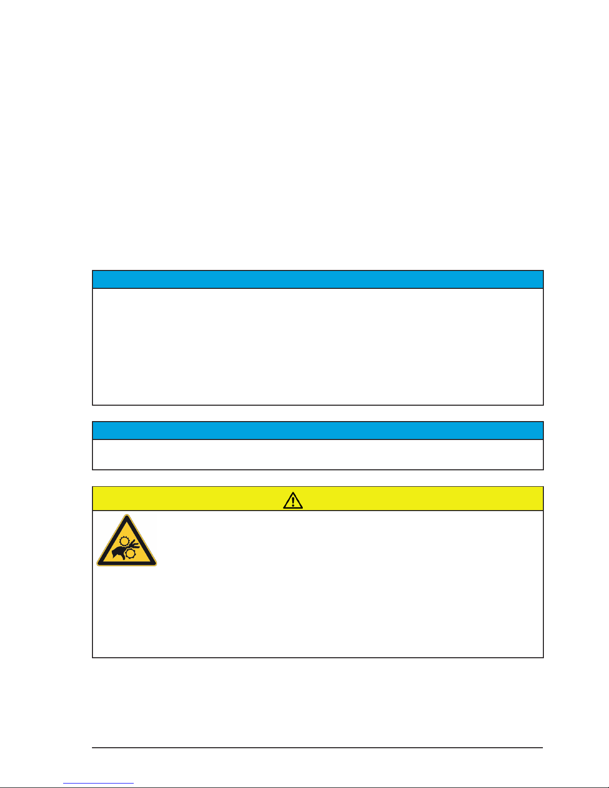
All content © 2018, cmotion GmbH. All specications are subject to change without further notice.
http://www.cmotion.eu
page 56 of 80
6.2.3.4. MOTORS
The motors menu contains all settings related to motor functions. These consist of:
Calibration all
Motor settings
Stealth mode
6.2.3.4.1. Calibration all
The calibration all menu allows you to calibrate all motors at once. Selecting calibration all
will calibrate all connected motors without further conrmation required.
NOTICE
The lens motors must be recalibrated under the following conditions:
- When a motor is detached from the lens
- After changing motors
- After changing lenses
- After a change in a motor position while powered down
NOTICE
Omitting motor calibration might lead to damage of the lens due to the high level of motor
torque!
CAUTION!
Risk of injury! Do not touch the motor gear while motor is powered up!
This device is not intended for use by children. Keep body parts out of the motion path.
Disconnect the plug if the device is not used for a longer period of time.
IEC 60417-6056 (2011-05) for other moving parts
Page 57
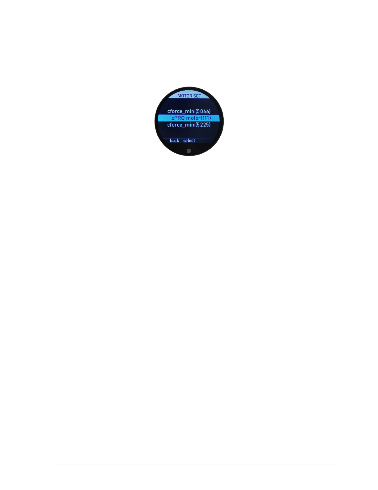
All content © 2018, cmotion GmbH. All specications are subject to change without further notice.
http://www.cmotion.eu
page 57 of 80
6.2.3.4.2. Motor settings
The motor settings menu contains all settings related to motor behaviour. Once you have
entered the motor settings menu, please select the motor you want to adjust from the
dynamic motor list.
Each motor menu consists of:
Axis (status)
Direction (status)
Ramp (status)
Torque (status)
Calibrate
6.2.3.4.2.1. Axis
The axis menu allows you to change the motor assigment to focus, iris or zoom.
Note: The axis menu changes the motor assignment not the assignemnt of the control
interface. With cforce motors you can change the motor assignment on the motor itself by
pressing the FIZ button. In order to change the motor assignement for a cPRO motor, please
refer to the cPRO motor user guide.
6.2.3.4.2.2. Torque
The torque menu allows you to adjust the strength of the motor to min, weak, strong and
max.
Note: Increasing the motor torque drains more power of the system and can place stress
on the lens. Only increase the torque as much is necessary, in order to achieve reactive and
uent lens control.
6.2.3.4.2.3. Direction
The direction menu allows you to set the side of the camera which the lens motor is
mounted on to either left or right.
Note: The direction is dened from the operators point of view, from behind the camera.
Page 58
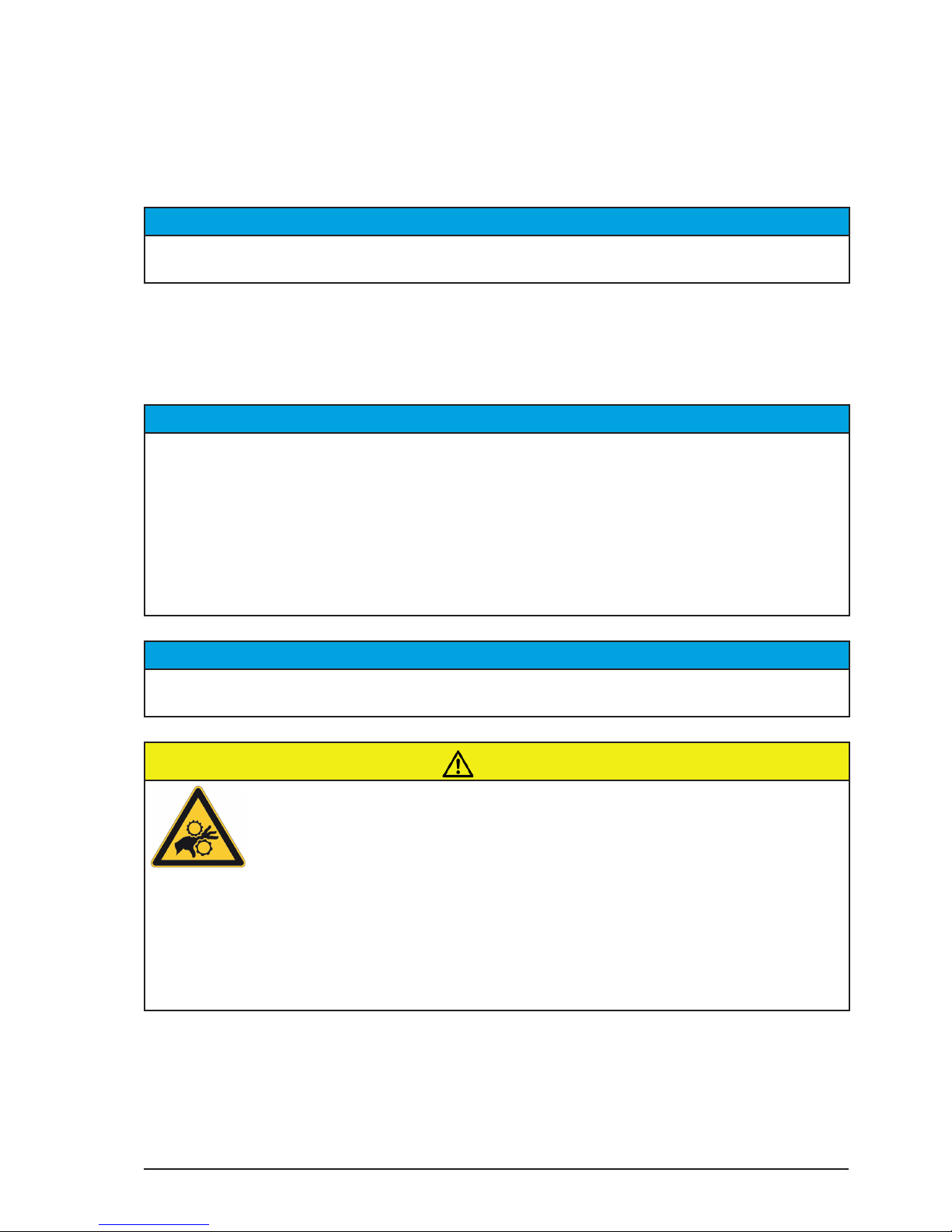
All content © 2018, cmotion GmbH. All specications are subject to change without further notice.
http://www.cmotion.eu
page 58 of 80
6.2.3.4.2.4. Ramp
The ramp menu allows you to adjust the start and stop acceleration of the motor to min,
short, long and max. This allows for both smooth speed-up and slow-down curves.
NOTICE
The motor settings menu can be reached from all motors main screens quickly by tapping and
holding the touch display or by pressing and holding menu button 2 (MB2).
6.2.3.4.2.5. Calibrate
The calibrate menu allows you to calibrate each motor axis individually. Selecting calibrate
will calibrate the corresponding lens motor without conrmation required.
NOTICE
The lens motors must be recalibrated under the following conditions:
- When a motor is detached from the lens
- After changing motors
- After changing lenses
- After a change in a motor position while powered down
NOTICE
Omitting motor calibration might lead to damage of the lens due to the high level of motor
torque!
CAUTION!
Risk of injury! Do not touch the motor gear while motor is powered up!
This device is not intended for use by children. Keep body parts out of the motion path.
Disconnect the plug if the device is not used for a longer period of time.
IEC 60417-6056 (2011-05) for other moving parts
6.2.3.4.3. Stealth mode
The stealth mode menu can activate and deactivate the cPRO’s stealth mode. When
stealth mode is on, the illumination of all LBUS connected cforce motors will be turned o
(e.g. if the camera angle is critical because of camera reection in the picture).
Page 59

All content © 2018, cmotion GmbH. All specications are subject to change without further notice.
http://www.cmotion.eu
page 59 of 80
6.2.3.5. RANGEFINDER
The rangender menu contains all settings related to the use of rangenders. This consists
of:
Oset
Limits
Sensitivity
Autofocus (status)
Laser pointer
Stealth mode
6.2.3.5.1. Oset
The oset menu allows you to input an oset measurement between the rangender’s
sensor and the camera’s sensor.
How to preceed:
Measure the distance from the datum line of the rangender to the sensor plane of your
camera and enter the measured distance into the oset menu usning the thumb wheel.
Conrm your settings by pressing select.
Note: If the rangender is mounted in front of the camera´s sensor plane, enter a positive
value. If the rangender is mounted behind the camera´s sensor plane enter a negative value.
6.2.3.5.2. Limits
The limit menu allows you to dene your range of interest. If in AF mode, autofocus will
be active in this range only.
How to preceed:
limit max: - use the thumb wheel to enter a far distance limit
- press next in order to switch to the next digits or to limit min
- press select in order to conrm your settings
Note: If in AF mode, focus will not be adjusted for measurements beyond limit max.
limit min: - use the thumb wheel to enter a close distance limit
- press next in order to switch to the next digits or to limit max
- press select in order to conrm your settings
Note: If in AF mode, focus will not be adjusted for measurements below limit min.
Note: The limits icon in the rangender main screen will turn green if a rangender limit other
than limit max = inf and limit min = 0 is set, otherwise the icon illuminates white.
Page 60

All content © 2018, cmotion GmbH. All specications are subject to change without further notice.
http://www.cmotion.eu
page 60 of 80
6.2.3.5.3. Sensitivity
The invisible laser used in cnder III makes 300 measurements every second. To make
this rapid distance information more suitable for both viewing and motorised lens control,
cnder III calculates an average distance that is then displayed on the screen and used to
control the focus motor when autofocus is active.
Sensitivity allows you to increase or decrease the rate at which the ‚average‘ value is
calculated. By increasing sensitivity, cnder III will display an increased number of distance
values per second and adjust the motor position accordingly (= faster / snap reaction).
By decreasing sensitivity, cnder III will display fewer distance values per second and
adjust the motor position accordingly (= slower / smoother reaction).
Note: To track a fast moving target, increase sensitivity for a faster motor response. To track
a slow moving or xed target, reduce sensitivity for a smoother motor response.
Note: Sensitivity is available with cmotion cnder III or with other rangenders via ARRI
LCUB-1 only.
6.2.3.5.4. Autofocus
Autofocus will seamlessly match distance measurement data from the rangender with
lens data from the cPRO hand unit to control the focus scale of the lens automatically.
If autofocus “on“ is selected within the autofocus menu, focus will be adjusted permanently
until turned o again.
Autofocus can be activated through a cPRO hand unit user function as well. This supports
various autofocus trigger options including autofocus press, autofocus toggle, and
autofocus pinpoint. (For further information, please refer to section “6.2.3.6. BUTTONS”
on page 61 in this manual)
Note: In order to use autofocus with a cPRO hand unit, a lens le needs to be loaded, a lens
motor needs to be connected, engaged with the lens and assigned to focus. (For further
information on how to create lens data, please refer to section “6.2.3.3. LENS” on page 42
in this manual or to the cworld user guide.)
6.2.3.5.5. Laser pointer
The laser pointer menu allows you to turn the rangender’s laser pointer on or o. When
the laser pointer is turned on, it will remain active for one minute before turning o
automatically. During this time, you can turn it o manually by selecting “o“
Note: The laser pointer icon in the rangender main screen turns green if the laser pointer is
on. If the laser pointer is o it illuminates white.
Note: The laser pointer can be activated through a cPRO hand unit user function as well.
This allows the laser to remain active as long as the user button is being pressed. (For further
information, please refer to section “6.2.3.6. BUTTONS” on page 61 in this manual.)
Note: All laser pointer functions are available with cmotion cnder III only.
Page 61

All content © 2018, cmotion GmbH. All specications are subject to change without further notice.
http://www.cmotion.eu
page 61 of 80
6.2.3.6. BUTTONS
The buttons menu allows you to assign user functions to any assignable user button on
the cPRO hand unit. Once a user function is assigned to a button, the button will illuminate
and the buttons assignment will be displayed in the buttons main screens. If the button is
assigned to no function (o) the corresponding user button will not be illuminated.
Note: With the exception of of the REC button, the HOME button and the menu button 2
(MB2) all other buttons can be assigned individually. All buttons, with the exception of the
back button, illuminate once assigned to a user function.
6.2.3.6.1. Assignable user buttons
Assignable user buttons User button functions
UB1
UB2
UB3
BB1
MB1
MB3
O
Focus limits set
Iris limits set
Zoom limits set
Focus calibration
Iris calibration
Zoom calibration
Calibration all
ZAP
Joystick speed up
Joystick speed down
Autofocus press
Autofocus toggle
Autofocus pinpoint
System unit
Steath mode
Laser pointer
Camera rec
Lock knob
Lock slider
Lock joystick
Lock thumb wheel
Page 62

All content © 2018, cmotion GmbH. All specications are subject to change without further notice.
http://www.cmotion.eu
page 62 of 80
6.2.3.6.2. User button functions
User button function Description
O turns the user button o / no function / the
user button illumination will turn o
Focus limits set please refer to the detailed explenation be-
low
Iris limits set please refer to the detailed explenation be-
low
Zoom limits set please refer to the detailed explenation be-
low
Focus calibration calibrates the focus motor only
Iris calibration calibrates the iris motor only
Zoom calibration calibrates the zoom motor only
Calibration all calibrates all connected motors at once
ZAP sets the joystick speed to maximum as
long as the button is being pressed
Joystick speed up turns the joystick speed up (press and hold
to speed the adjustment up)
Joystick speed down turns the joystick speed down (press and
hold to speed the adjustment up)
Autofocus press activates autofocus as long as the user
button is being pressed / after releasing
the user button, the focus will move to the
preset knob position.
Autofocus toggle activates autofocus by a single press of the
user button / press again to deactivate /
after deactivating the autofocus, the focus
will move to the preset knob position
Autofocus pinpoint please refer to the detailed explenation be-
low
System unit changes the scale units between imperial
or metric
Steath mode all turns the illumination of all LBUS devices
on the camera side o or on
Laser pointer turns the laser pointer on as long as the
button is being pressed
Camera rec starts and stops the camera
Lock knob digitally locks and unlocks the knob
Lock slider digitally locks and unlocks the slider
Lock joystick digitally locks and unlocks the joystick
Lock thumb wheel digitally locks and unlocks the thumb wheel
Page 63
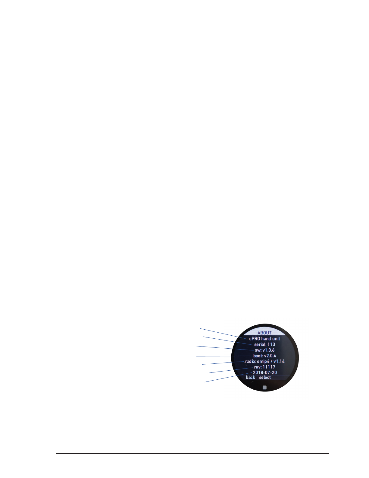
All content © 2018, cmotion GmbH. All specications are subject to change without further notice.
http://www.cmotion.eu
page 63 of 80
Focus limits set: This user button function allows you to limit the focus scale to a certain
range. If you move the controller beyond this range, its position will not be forwarded to
the lens motor. The lens motor will move within the set range only. The focus limit function
works like a digital end stop.
Iris limits set: This user button function allows you to limit the iris scale to a certain range.
If you move the controller beyond this range, its position will not be forwarded to the lens
motor. The lens motor will move within the set range only. The iris limit function works like
a digital end stop.
Zoom limits set: This user button function allows you to limit the zoom scale to a certain
range. If you move the controller beyond this range, its position will not be forwarded to
the lens motor. The lens motor will move within the set range only. The zoom limit function
works like a digital end stop.
Autofocus pinpoint: This user button function takes continuous readings from the
rangender and focuses automatically. If the user button is pressed and held, autofocus
will remain active until the button is relased. After releasing the user button, the focus
will stay at the last measured distance. Turning the knob over the xed focus position,
assigns the control back to the knob automatically.
6.2.3.7. ABOUT
The about menu displays information about the current rmware installed on the cPRO
hand unit and each connected component. It also allows you to update rmware and
perform a factory reset. The menu consists of:
cPRO hand unit
LBUS DEVICES
Firmware update
Factory reset
6.2.3.7.1. cPRO hand unit
1 Device ID
2 Serial number
3 Software version
4 Bootloader version
5 Radio module ID / rmware version
6 Revision number
7 Built date
The cPRO hand unit ABOUT menu shows you all relevant data about your cPRO hand
unit.
Note: Please have this data available, if contacting the cmotion support team with any
technical enquiries.
1
2
3
4
6
5
7
Page 64
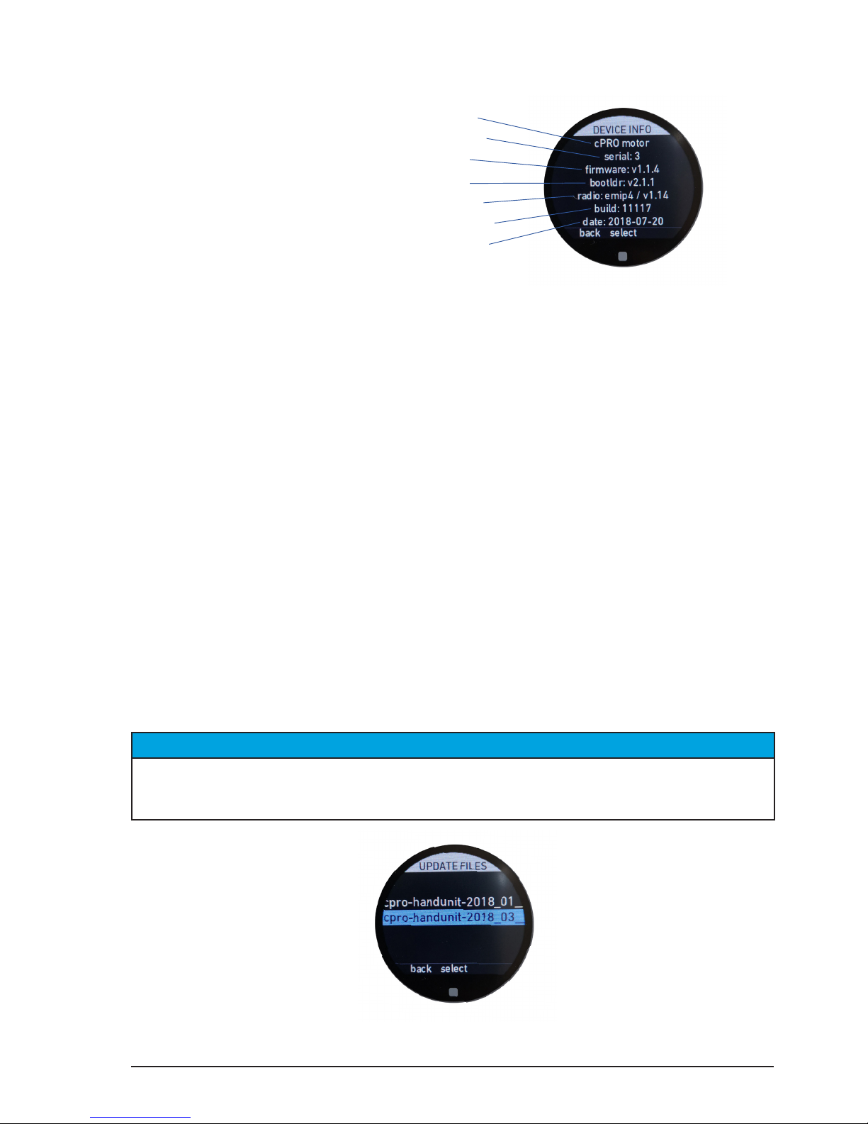
All content © 2018, cmotion GmbH. All specications are subject to change without further notice.
http://www.cmotion.eu
page 64 of 80
6.2.3.7.2. LBUS devices
1 Device ID
2 Serial number
3 Software version
4 Bootloader version
5 Radio module ID / rmware version
6 Revision number
7 Built date
The LBUS device ABOUT menu shows you all relevant data about the connected LBUS
devices. Please select the LBUS device form the dynamic list of devices you want more
information on.
Note: Please have this data available, if contacting the cmotion support team with any
technical enquiries.
6.2.3.7.3. Firmware update
The rmware update menu allows you to update your cPRO hand unit as well as other
connected LBUS devices.
Note: In order to perform an update, a USB stick formated in ExFAT or FAT32 loaded with
the appropriate update le for the cPRO hand unit or an other LBUS device needs to be
inserted in the USB slot on the back side of the cPRO hand unit. The USB drive will be
recognized and mounted automatically.
Please select cPRO hand unit if you want to update your hand unit or LBUS devices and
the corresponding LBUS device form the dynamic list if you want to update another LBUS
product. The update procedure is the same for any device as follows.
NOTICE
In order to update LBUS devices, the cPRO hand unit needs to be hard-wired to the
corresponding LBUS device using any LCB cable. The cPRO motor and cPRO camin can
also be updated through their CAM interface using the cable CAM (7p) - LBUS [K2.0015760].
Please select the update le form the USB drive which you want to up- or down-grade to.
1
2
3
4
6
5
7
Page 65
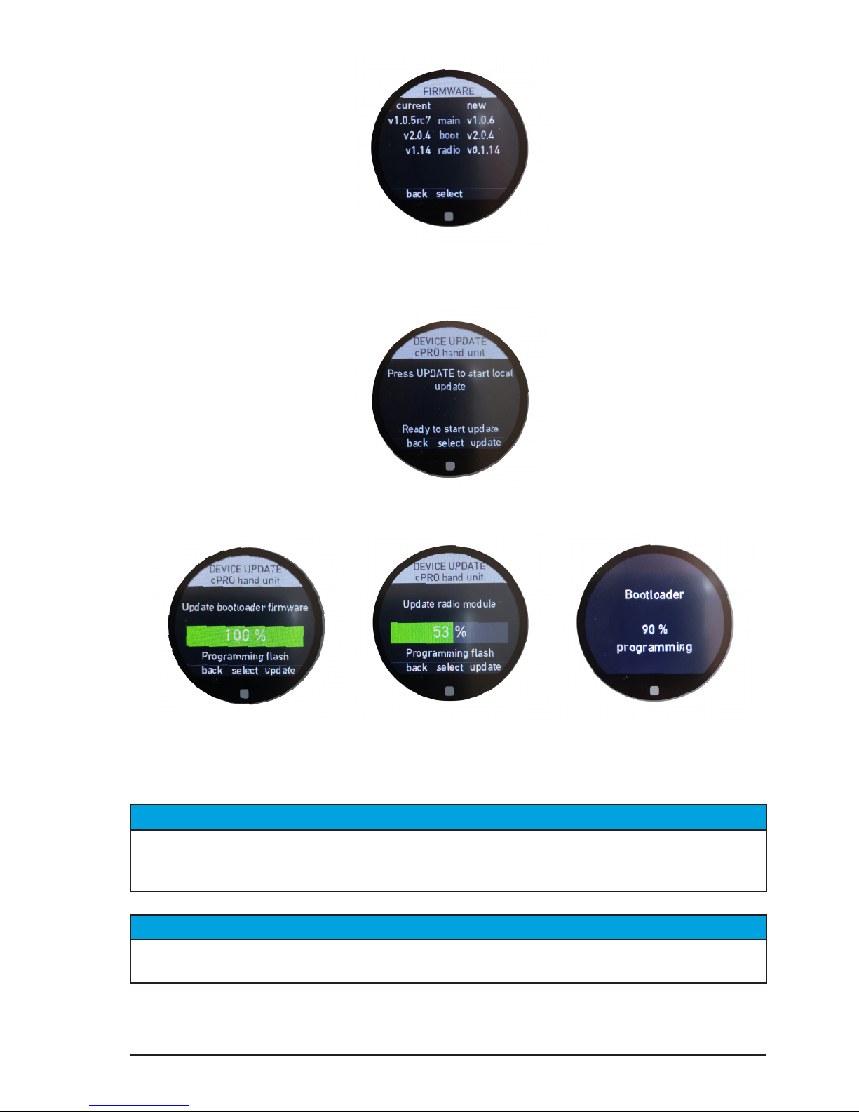
All content © 2018, cmotion GmbH. All specications are subject to change without further notice.
http://www.cmotion.eu
page 65 of 80
Please check the current rmware status and the new rmware upgrade option. Press
select if you want to procceed, press back if you want to select another update le.
Please conrm the update by pressing update. Press back to return to the previous page.
The update will procceed in various steps if required updating your main software, your
radio module and your bootloader software. Once nished the cPRO hand unit or the
connected LBUS device will restart automatically.
NOTICE
Please ensure the battery of the cPRO hand unit is completely charged before starting any
update! Do not remove the battery or the USB drive from the cPRO hand unit while the update
is in progress!
NOTICE
Do not power o the cPRO hand unit or the connected LBUS devices while the update is in
progress as this may damage the device!
Note: Please check cmotion`s website for the latest rmware packages.
Page 66
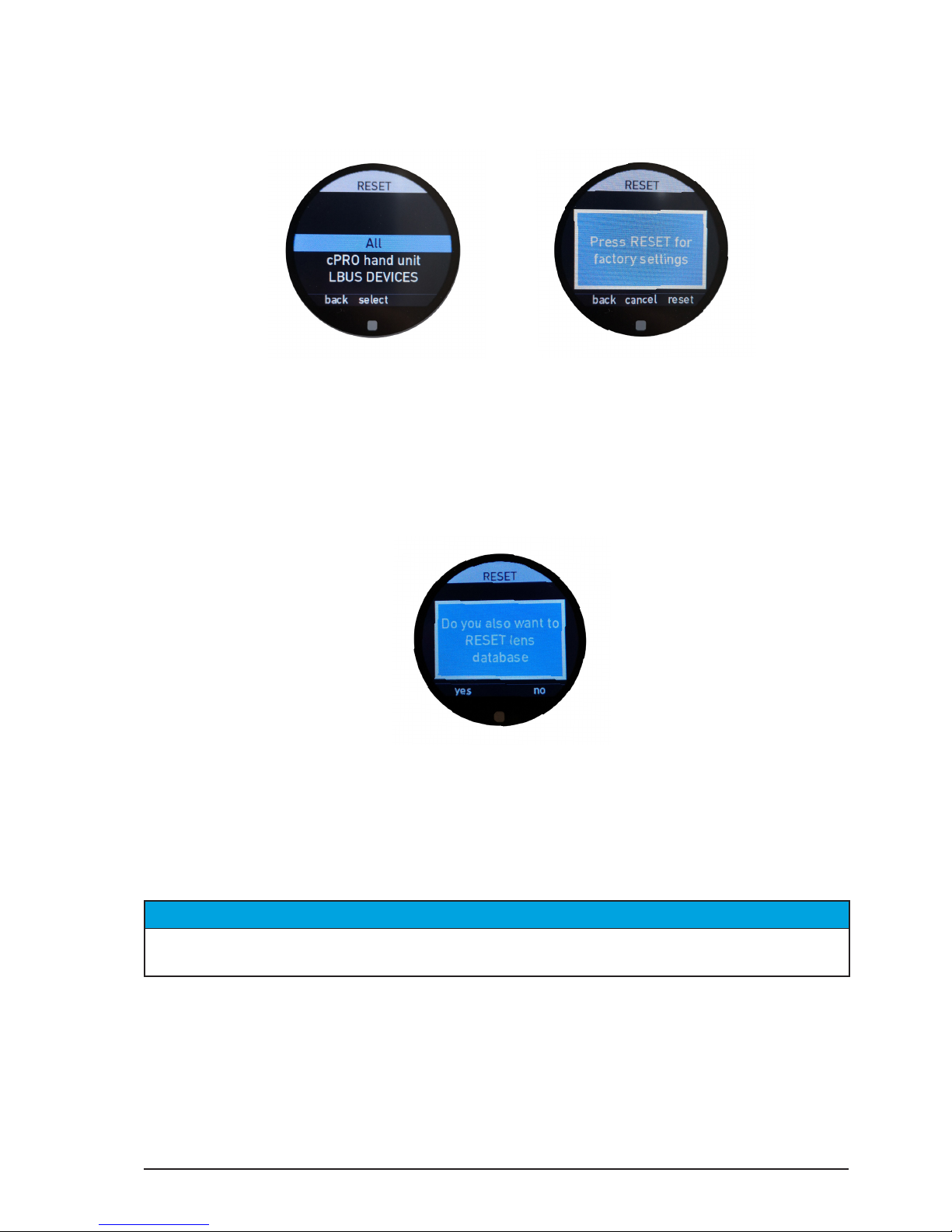
All content © 2018, cmotion GmbH. All specications are subject to change without further notice.
http://www.cmotion.eu
page 66 of 80
6.2.3.7.4. Factory reset
The factory reset menu allows you to reset the cPRO hand unit and all connected LBUS
devices to manufacturer settings.
Please select all if you want to reset all connected LBUS devices and the cPRO hand unit.
Select cPRO hand unit if you want to reset the cPRO hand unit only. Select LBUS devices
and then one device from the dynamic LBUS device list if you want to reset a specic
LBUS device only.
Please conrm your selection by pressing reset in order to reset the selected device or
back / cancel in order to cancel the procedure.
When performing a factory reset on the cPRO hand unit, you will be asked to conrm
whether you also want to reset the internal lens database. If you do want to delete ALL
lens les saved on the cPRO hand unit, press “yes”. Press “no” to perform a factory reset
without deleting the entire lens database.
NOTICE
Do not power o the cPRO hand unit or the connected LBUS devices while the factory reset
is in progress as this may damage the device!
Page 67
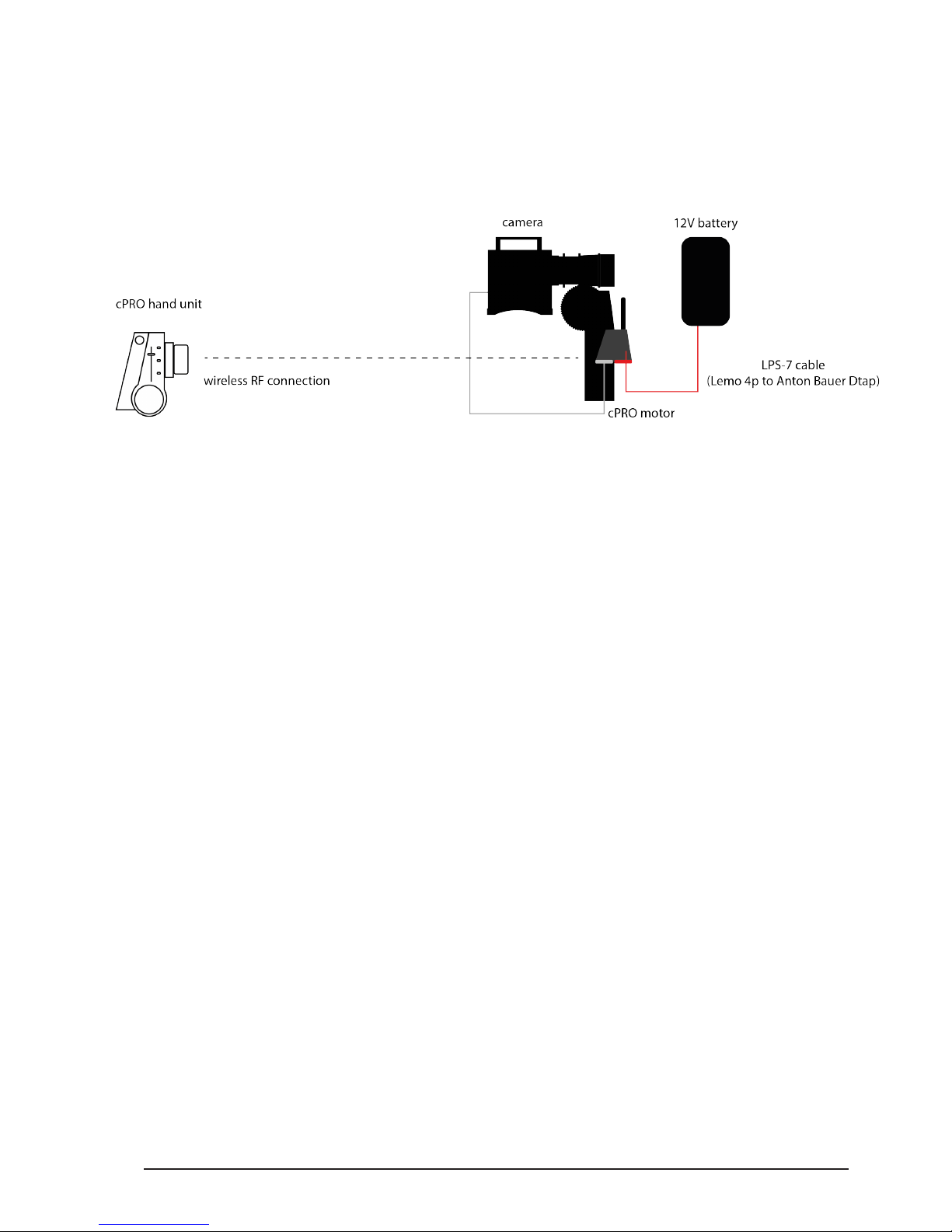
All content © 2018, cmotion GmbH. All specications are subject to change without further notice.
http://www.cmotion.eu
page 67 of 80
7. Setting up the cPRO system
7.1. using the cPRO motor
7.1.1. Mounting and connecting cables:
• mount the cPRO motor on a 15mm / 19mm support rod and engage it with the lens
(please refer to the cPRO motor manual)
• mount the cforce motors on the 15mm /19mm support rod and engage with the lens
(please refer to the cforce motor manual)
Note: Up to 2 additional cforce motors can be daisy-chained using any LCB cable from one
motor to the other.
• connect the cPRO motor to the power supply e.g. D-Tap battery using cable LPS-7.
• depending on your camera, connect the corresponding camera interface cable
between the CAM port on the cPRO motor and the camera.
7.1.2. Setting up cPRO hand unit and cPRO motor
7.1.2.1. Establishing a wireless RF connection
• turn on the cPRO hand unit by pressing the HOME button
• select the same RF channel on the cPRO hand unit and the cPRO motor
• cPRO hand unit: double press the HOME button to enter the adjustment menu;
go to MAIN / RADIO / Channel to change the RF channel (0-13)
• cPRO motor: press the lower button to change the RF channel (0-13)
Note: The RF connection will be established automatically
Note: please double check if the region settings are set to the region you are located in.
• cPRO hand unit: double press the HOME button to enter menu; go to MAIN /
RADIO / Region to change the region settings. The region will be set on the cPRO
motor automatically.
Page 68
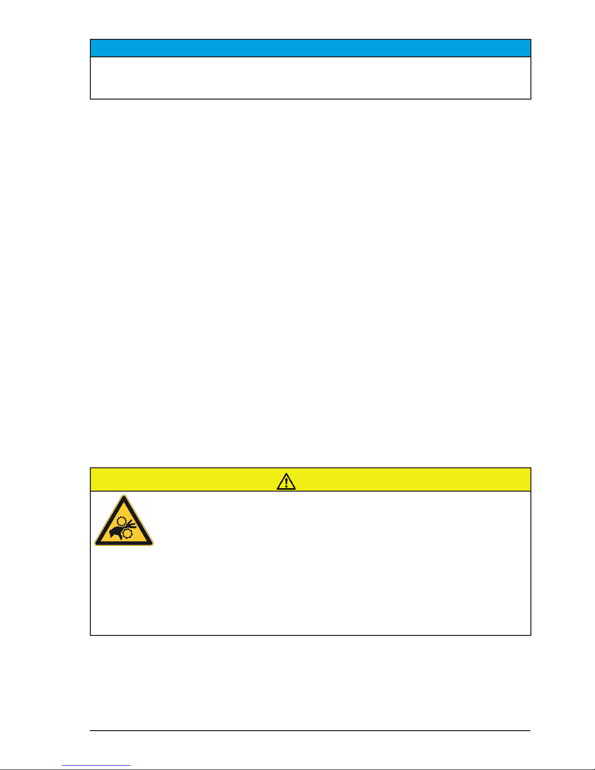
All content © 2018, cmotion GmbH. All specications are subject to change without further notice.
http://www.cmotion.eu
page 68 of 80
NOTICE
It may not be legal to operate the cPRO hand unit in a country/region other than the country/
region selected in the region menu. Select ROW (Rest of world) or use the device in hard-
wired mode if you are unsure of the correct region setting.
Note: If multiple hand units are used, please set all cPRO hand units you want to connect
to the network to the same radio channel as the cPRO motor. Once a cPRO hand unit is set
to the same radio channel like the cPRO motor, the device will connect automatically. Up
to 3 cPRO hand units can be connected to a cPRO motor at a time (available with Software
Release Package v2.0 / license required for each hand unit).
7.1.2.2. Assigning the cPRO and other motor’s control axis
• To assign the cPRO motor to the corresponding lens axis, press the upper button
repeatedly until the correct axis name is displayed.
• To assign a cforce mini or cforce plus motor to the corresponding lens axis, press the
FIZ button repeatedly until the correct axis character is illuminated.
(F=Focus / I=Iris / Z=Zoom)
• alternatively assign the cPRO / cforce motors control axis using the cPRO hand unit;
double press the HOME button to enter the adjustment menu; go to MOTORS / Motor
Settings /select the right motor / Axis
7.1.2.3. Calibrating the cPRO / cforce motors
• calibrate the cPRO motor by pressing and holding the upper button for 3 seconds
• calibrate the cforce motors by pressing and holding the FIZ button on each cforce
motor for 3 seconds
• alternatively calibrate the cPRO / cforce motors using one of the cPRO hand unit
functions „calibrate“ e.g. double press the HOME button to enter the adjustment
menu; go to MOTORS / Calibrate all)
CAUTION!
Risk of injury! Do not touch the motor gear while motor is powered up!
This device is not intended for use by children. Keep body parts out of the motion path.
Disconnect the plug if the device is not used for a longer period of time.
IEC 60417-6056 (2011-05) for other moving parts
Page 69
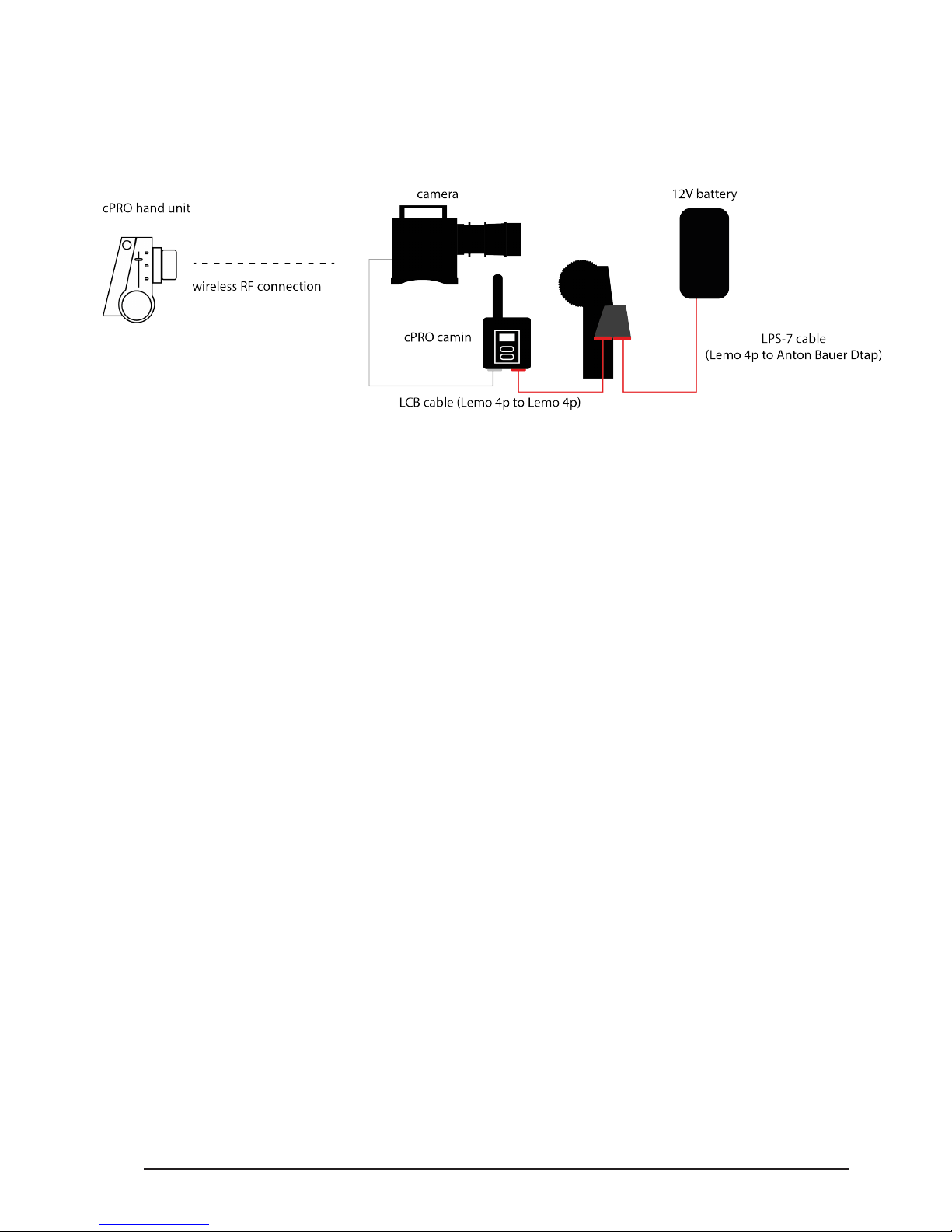
All content © 2018, cmotion GmbH. All specications are subject to change without further notice.
http://www.cmotion.eu
page 69 of 80
7.2. using the cPRO camin
with cforce motors
7.2.1. Mounting and connecting cables:
• mount the cPRO camin on the camera using e.g the cPRO camin bracket
(please refer to the cPRO camin manual)
• mount the cforce motors on the 15mm / 19mm support rods and engage them with
the lens (please refer to the cforce motor manual)
Note: Up to 3 cforce motors can be daisy-chained using LCB cables from one motor to the
other.
• connect the cPRO camin with the rst cforce motor using a LCB cable
(e.g. cable LCB-A)
• connect the last cforce motor in the daisy-chain to the D-Tap power source using
cable LPS-7.
• for camera data and run/stop control, connect the corresponding camera interface
cable to the camera and the CAM connector to the cPRO camin
7.2.2. Setting up cPRO hand unit and cPRO camin
7.2.2.1. Establishing a wireless RF connection
• turn on the cPRO hand unit by pressing the HOME button
• select the same RF channel on the cPRO hand unit and the cPRO camin
• cPRO hand unit: double press the HOME button to enter the adjustment menu; go
to MAIN / RADIO / Channel to change the RF channel (0-13)
• cPRO camin: press the lower or upper button to change the RF channel (0-13) up
or down
Note: The RF connection will be established automatically
Note: please double check if the region settings are set to the region you are located in.
• cPRO hand unit: double press the HOME button to enter menu; go to MAIN /
RADIO / Region to change the region settings. The region will be set on the cPRO
camin automatically.
Page 70
All content © 2018, cmotion GmbH. All specications are subject to change without further notice.
http://www.cmotion.eu
page 70 of 80
NOTICE
It may not be legal to operate the cPRO hand unit in a country/region other than the country/
region selected in the region menu. Select ROW (Rest of world) or use the device in hard-
wired mode if you are unsure of the correct region setting.
Note: If multiple hand units are used, please set all cPRO hand units you want to connect
to the network to the same radio channel as the cPRO camin. Once a cPRO hand unit is set
to the same radio channel like the cPRO camin, the device will connect automatically. Up
to 3 cPRO hand units can be connected to a cPRO camin at a time (available with Software
Release Package v2.0 / license required for each hand unit).
7.2.2.2. Assigning the motor’s control axis
• To assign a cforce mini or cforce plus motor to the corresponding lens axis, press
the FIZ button repeatedly until the correct axis character is illuminated.
(F=Focus / I=Iris / Z=Zoom)
• alternatively, assign the cforce motors control axis using the cPRO hand unit; double
press the HOME button to enter the adjustment menu; go to MOTORS / Motor
Settings /select the corresponding motor / Axis
7.2.2.3. Calibrating the cforce motors
• calibrate the cforce motors by pressing and holding the FIZ button on each cforce
motor for 3 seconds
• alternatively calibrate the cforce motors using one of the cPRO hand unit functions
„calibrate“ e.g. double press the HOME button to enter the adjustment menu; go to
MOTORS / Calibrate all
CAUTION!
Risk of injury! Do not touch the motor gear while motor is powered up!
This device is not intended for use by children. Keep body parts out of the motion path.
Disconnect the plug if the device is not used for a longer period of time.
IEC 60417-6056 (2011-05) for other moving parts
Page 71
All content © 2018, cmotion GmbH. All specications are subject to change without further notice.
http://www.cmotion.eu
page 71 of 80
8. Compatibility
The cPRO hand unit is directly compatible with the following cmotion / ARRI products:
■ cPRO motor / cPRO camin
■ cforce mini lens motor
■ cforce plus lens motor
■ cdistance
■ cnder III
■ steady zoom / pan-bar zoom
■ UDM-1 (Ultrasonic Distance Measure) via LCUBE CUB-1
■ Master Grips
Note: run/stop control is supported for all standard digital cameras (ARRI, BLACKMAGIC,
CANON, RED, SONY, PANAVISION) using optional CAM interface cables.
9. Power connection and
disconnection
9.1. Power connection
Warning!
Requirement for the external power supply:
Limited power source according to IEC60950-1 or PS2 classied IEC62368-1 and short-
circuit current < 8A.
9.2. Power disconnection
CAUTION!
To disconnect the device safely from the power source, remove the cable connector from the
cPRO hand unit´s LBUS port.
Mount and operate the device in an orientation to ensure easy access to the connectors.
Page 72
All content © 2018, cmotion GmbH. All specications are subject to change without further notice.
http://www.cmotion.eu
page 72 of 80
10. Appendix
10.1. Antenna connector
Radio connection can be established between the cPRO hand unit and cPRO motor / cPRO
camin when an antenna is mounted on each device. It is recommended to only use certied
antennas supplied by cmotion.
Warning!
Please ensure the antenna connector is covered by the antenna or the safety cap at any
time. The radio module can suer damage from electrostatic discharge if the antenna
connector is left exposed.
10.2. Specications
Electrical data
Temperature range: -20 to +50° C (-4 to +122° F)
Battery type: NP-FM500H, 7,2V, 2040mAh
Warning!
To reduce risk of re or burns using the NP-FM500H battery, do not disassamble, crush,
puncture short external contacts or dispose o re and water.
CAUTION!
Only the originally supplied battery should be used with the cPRO hand unit.
Radio system
The cPRO hand unit contains a radio unit that enables wireless lens control with a red coded
radio module. A red ring at the base of the antenna mount on both the cPRO motor and
cPRO camin identies this. There are 14 channels to choose from:
Channel Frequency
0 2.410 GHz
1 2.415 GHz
2 2.430 GHz
3 2.435 GHz
4 2.450 GHz
5 2.455 GHz
6 2.470 GHz
7 2.475 GHz
Page 73
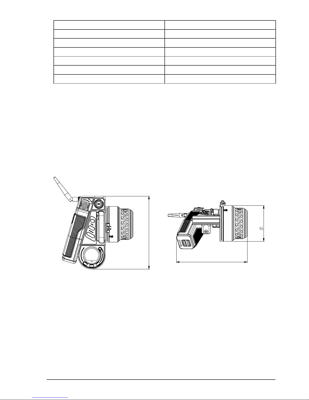
All content © 2018, cmotion GmbH. All specications are subject to change without further notice.
http://www.cmotion.eu
page 73 of 80
Channel Frequency
8 2.420 GHz
9 2.425 GHz
10 2.440 GHz
11 2.445 GHz
12 2.460 GHz
13 2.465 GHz
Note: cmotion red radio and ARRI white radio are not compatible. This means the cPRO
hand unit will not communicate with an ARRI white enabled camera or UMC. However,
because both modules use the same radio frequency, it is important to have each system
set to a dierent radio channel when being used in parallel.
10.3. Dimensions and weight
Dimensions:
Weight:
cPRO hand unit: appx. 0,89 kg (< 32 oz) (incl. battery and antenna)
3
6
7
?
9
80,50
160
164,3
POS-NR.
BENENNUNG
BESCHREIBUNG
ID-Nr
1
C0EK_G20_Mittelkonsole
Center Console / Mittelkonsole
K4.0016694
2
C0EK_G60_Knob
ASM Knob / BG Drehknopf
K4.0018914
3
C0EK_T10_Handgriff
ASM Grip / BG Handgriff
K4.0017075
4
C0EK_G50_Schnellbefestigung
ASM Quick Fastening / BG Schnellbefest.
K2.0019832
5
C0EK_G92_Typenschild
Nameplate / Typenschild
K5.0018927
6
ISO 14583 TX - M3 - 30mm
Flachkopfschraube TX - M3 - 30mm
50.0016229
7
ISO 14583 TX - M3 - 8mm
Flachkopfschraube TX - M3 - 8mm
O5.17028.0
8
Dipol Antenne Dipole Antenna / Dipol Antenne
K2.0001996
9
Vinylabdeckkappe
Cap / Abdeckkappe
O5.21965.0
protection notice DIN EN ISO 16016 |
Schutzvermerk nach ISO 16016 beachten
BG
09.01.18
MT
+0,1
-0,25
0
-0,15
C0EK
cPro-basic
cm
2
803g
Edges |
Werkstückkanten
DIN ISO 13715
Surface area|
Oberfläche
Mass | Masse
Toleration
Gen.-tol.
DIN 7167
ISO2768-fH
Surface treatment | Oberfl. Behandlung
Surface finish to |
Oberfläche nach
DIN ISO 1302
Material
25.08.2017
Name
Date
Checked
Created
Scale | Maßstab
Title | Bennenung
Project | Projekt
Filename | Dateiname
Date
Cng.Nr.
ID-Nr.:
Ver
K2.0016602
00
01
02
W01360
W01298
F06585
14.08.2018
06.04.2018
09.01.2018
7
6
5
4
3
2
1
03
W0
7
?
80,50
160
POS-NR.
BENENNUNG
BESCHREIBUNG
ID-Nr
1
C0EK_G20_Mittelkonsole
Center Console / Mittelkonsole
K4.0016694
2
C0EK_G60_Knob
ASM Knob / BG Drehknopf
K4.0018914
3
C0EK_T10_Handgriff
ASM Grip / BG Handgriff
K4.0017075
4
C0EK_G50_Schnellbefestigung
ASM Quick Fastening / BG Schnellbefest.
K2.0019832
5
C0EK_G92_Typenschild
Nameplate / Typenschild
K5.0018927
6
ISO 14583 TX - M3 - 30mm
Flachkopfschraube TX - M3 - 30mm
50.0016229
7
ISO 14583 TX - M3 - 8mm
Flachkopfschraube TX - M3 - 8mm
O5.17028.0
8
Dipol Antenne Dipole Antenna / Dipol Antenne
K2.0001996
9
Vinylabdeckkappe
Cap / Abdeckkappe
O5.21965.0
protection notice DIN EN ISO 16016 |
Schutzvermerk nach ISO 16016 beachten
7
6
5
4
3
2
1
Page 74

All content © 2018, cmotion GmbH. All specications are subject to change without further notice.
http://www.cmotion.eu
page 74 of 80
10.4. Pinouts
The cPRO hand unit is equipped with one LBUS connector (Lemo 4 pin).
LBUS connector
1 GND
2 CAN-L
3 V-BAT
4 CAN-H
10.5. Part numbers
K2.0016602 cPRO hand unit basic set
The cPRO hand unit basic set includes:
■ cPRO hand unit unit
■ K2.0001996 swivel antenna for SMC-1, EMC-1, AMC-1, cPRO hand unit /
motor / camin
■ K2.0019833 cPRO plain white iris strip
■ K2.0020890 plain white focus ring for cPRO hand unitK2.0019832 cPRO truss
NOTICE
The cPRO hand unit basic set does not include an LBUS or CAM cable. LBUS cables are
available in various lengths and need to be ordered separately.
Antenna part numbers
Radiall/Larsen K2.0002007 Dipole / Reverse SMA
Wanshih 50.0013627 Dipole / Reverse SMA
Proant K2.0001996 Dipole / Reverse SMA
Nearson O5.20112.0 Dipole / Reverse SMA
Page 75

All content © 2018, cmotion GmbH. All specications are subject to change without further notice.
http://www.cmotion.eu
page 75 of 80
Accessories: The following accessories are compatible with the cPRO hand unit:
K2.0019832 cPRO truss
K2.0019827 cPRO monitor bracket
K2.0019830 cPRO v-lock plate
K2.0019824 cmotion battery
K2.0019822 cmotion battery charger
Focus rings / Iris strips:
K2.0020890 plain white focus ring for cPRO hand unit
K2.0019833 plain white iris strip for cPRO hand unit
Pre-marked focus ring sets:
K2.0019834 pre-marked focus ring imperial set
K2.0019835 pre-marked focus ring metric set
Pre-marked focus rings:
K2.0020897 pre-marked focus ring 3 feet 6 inch for cPRO hand unit
K2.0020904 pre-marked focus ring 20 inch for cPRO hand unit
K2.0020903 pre-marked focus ring 14 inch for cPRO hand unit
K2.0020902 pre-marked focus ring 12 inch for cPRO hand unit
K2.0020901 pre-marked focus ring 8 inch for cPRO hand unit
K2.0020896 pre-marked focus ring 1.0m for cPRO hand unit
K2.0020891 pre-marked focus ring 0.5m for cPRO hand unit
K2.0020894 pre-marked focus ring 0.35m for cPRO hand unit
K2.0020893 pre-marked focus ring 0.25m for cPRO hand unit
K2.0020892 pre-marked focus ring 0.20m for cPRO hand unit
Pre-marked iris strips:
K2.0019836 pre-marked iris strip T 22-2.8 for cPRO hand unit
K2.0019838 pre-marked iris strip T 22-2.0 for cPRO hand unit
K2.0019837 pre-marked iris strip close- T 1.0 for cPRO hand unit
Page 76

All content © 2018, cmotion GmbH. All specications are subject to change without further notice.
http://www.cmotion.eu
page 76 of 80
Camera interface cables:
K2.0015754 Cable CAM (7p) - RS
Connects ARRI cforce RF motor / cmotion cPRO motor and camin to RS connector.
Provides power, camera RUN/STOP and tally function on ARRI WCU-4 / cmotion cPRO
hand unit.Works with ALEXA and AMIRA cameras.
K2.0015755 Cable CAM (7p) - EXT (16p)
Connects ARRI cforce RF motor / cmotion cPRO motor and camin to the EXT connector of
an ALEXA EV camera.
Provides camera RUN/STOP function, tally and camera status information on ARRI WCU-4
/ cmotion cPRO hand unit.
K2.0015756 Cable CAM (7p) - EXT (6p)
Connects ARRI cforce RF motor / cmotion cPRO motor and camin to AMIRA EXT connector.
Provides camera RUN/STOP function, tally, camera status information and remote camera
set up with ALEXA Remote Licence on ARRI WCU-4 / cmotion cPRO hand unit.
K2.0015757 Cable CAM (7p) - LANC/D-Tap
Connects ARRI cforce RF motor / cmotion cPRO motor and camin to LANC connectors (e.g.
Canon C300 / C500) and D-Tap power source.
Provides camera RUN/STOP function and tally on ARRI WCU-4 / cmotion cPRO hand unit.
K2.0015758 Cable CAM (7p) - RED CTRL/D-Tap
Connects ARRI cforce RF motor / cmotion cPRO motor and camin to RED CTRL connector
on RED Epic DSMC-2 and RED Weapon cameras and D-Tap power source.
Provides camera RUN/STOP function, tally, camera status information and control of EF
lenses on ARRI WCU-4 / cmotion cPRO hand unit.
K2.0015759 Cable CAM (7p) - ENG (12p)
Connects ARRI cforce RF motor / cmotion cPRO motor and camin to the AMIRA/ALEXA
Mini or 3rd-party cameras Lens connector.
Provides camera RUN/STOP function, tally and camera status information on ARRI WCU-4
/ cmotion cPRO hand unit.
Page 77

All content © 2018, cmotion GmbH. All specications are subject to change without further notice.
http://www.cmotion.eu
page 77 of 80
K2.0018814 Cable CAM (7p) - Sony F5/55 CTRL/D-Tap
Connects ARRI cforce RF motor / cmotion cPRO motor and camin to Sony F5/F55/Venice
cameras and D-Tap power source.
Provides camera RUN/STOP function and tally.
K2.0015760 Cable CAM (7p) - LBUS
Connects ARRI cforce RF motor / cmotion cPRO motor and camin to LBUS devices or
LBUS power source.
Provides power to LBUS daisy chain or LBUS device features on ARRI WCU-4 / cmotion
cPRO hand unit.
Note: REQUIRED for cPRO motor / camin rmware update.
Power cables:
K2.0018813 Cable CAM (7p) - D-Tap
Connects ARRI cforce RF motor / cmotion cPRO motor and camin CAM connector to D-Tap
power source.
K2.0006758 Cable LPS-7
Connects ARRI cforce RF motor / cmotion cPRO motor and camin LBUS connector to
D-Tap power source.
Page 78

All content © 2018, cmotion GmbH. All specications are subject to change without further notice.
http://www.cmotion.eu
page 78 of 80
10.6. Service contacts
1. cmotion GmbH
Wiedner Hauptstraße 135/B3
1050 Wien
http://www.cmotion.eu
[email protected]
+43 1 7891096
2. camadeus Film Technologies, Inc.
314 N. Victory Blvd.
Burbank, CA 91502
http://www.camadeus.com
[email protected]
Service Hotline +1 (321) 345-6765
3. ARRI China (Beijing) Co. Ltd
China, Chaowai SOHO Suite C0656
Chaowai Dajie Yi 6, Chaoyang Qu,
100020, Beijing
Page 79

All content © 2018, cmotion GmbH. All specications are subject to change without further notice.
http://www.cmotion.eu
page 79 of 80
10.7. International declarations
EU-Declaration of Conformity
This designated product conforms with the specications of the following European directives:
Directive 2014/53/EU of the European Parliament and the Council of 16 April 2014 on the
harmonization of the laws of the Member States relating to the making available on the market
of radio equipment and repealing Directive - OJ L 153, 22.5.2014, S. 62–106.
Directive 2011/65/EU of the European Parliament and the Council of 8 June 2011 on
the restriction of the use of certain hazardous substances in electrical and electronic
equipment - OJ L 174, 1.7.2011, S. 88–110.
The compliance with the requirements of the European Directives was proved by the application
of the following standards:
■ EN 62368-1:2014 + AC:2015-05 + AC:2015-11
■ EN 301 489-1 V2.1.1; EN 301 489-17 V3.1.1
■ EN 300 328 V2.1.1
■ EN 50581:2012
To evaluate the respective information we used:
http://ec.europa.eu/growth/single-market/european-standards/harmonised-standards/index_
en.htm
FCC Class A Statement
Note: This equipment has been tested and found to comply with the limits for a Class A
digital device, pursuant to Part 15 of the FCC Rules. These limits are designed to provide
reasonable protection against harmful interference when the equipment is operated in a
commercial environment. This equipment generates, uses, and can radiate radio frequency
energy and, if not installed and used in accordance with the instruction manual, may cause
harmful interference to radio communications. Operation of this equipment in a residential
area is likely to cause harmful interference in which case the user will be required to correct
the interference at his own expense.
Industry Canada Compliance Statement
Complies with the Canadian ICES-003 Class A specications.
Cet appareil numérique de la Classe A est conforme à la norme NMB-003 du Canada. This device
complies with RSS 210 of Industry Canada. Cet appareil est conforme à CNR-210 d’Industrie
Canada. This Class A device meets all the requirements of the Canadian interference-causing
equipment regulations. Cet appareil numérique de la Classe A respecte toutes les exigences
du Réglement sur le matériel brouilleur du Canada.
Page 80

All content © 2018, cmotion GmbH. All specications are subject to change without further notice.
http://www.cmotion.eu
page 80 of 80
Japan MIC Statement
Complies with Ministry of Internal Aairs and Communications notication Article 88, Annex 43.
Radio Module
The cPRO hand unit contains the following radio module:
FCC ID: Y7N-EMIP400
IC ID: 9482A-EMIP400
CMIT ID: 2017DJ7863C(M)
MIC ID: 020-180030
NCC: CCAH18LP0660T0
KC: R-CRM-ARg-EMIP400
EMIP400s: ETA:1385/2018/ERLO
 Loading...