

CMOSTEK CMT2300AW User Manualline

AN148
Rev 0.8 | Page 1/13
www.cmostek.com
Summary
The CMT2300AW evaluation platform is designed to help users evaluate the performance of
CMOSTEK's wireless transceiver chip CMT2300AW. The evaluation platform consists of a pair of universal
wireless evaluation boards (RF-EB) and a pair of wireless modules(CMT2300AW-EM). Users can evaluate
the main characteristics of the CMT2300AW chip through the platform, such as the actual environment
communication distance, signal strength and packet loss rate.
The part numbers covered in this document are shown below.
Table1. The part numbers covered in this document
Part No.
Frequency
Modem
Function
Configuration
Package
CMT2300AW
127 - 1020MHz
(G)FSK/OOK
Transceiver
Register
QFN16
AN148
CMT2300AW RF-EB User Guideline
Copyright © By CMOSTEK

AN148
Rev 0.8 | Page 2/13
www.cmostek.com
Table of Contents
Summary .......................................................................................................................................................... 1
1. Hardware Platform ................................................................................................................................... 3
1.1 Evaluation Motherboard (RF-EB) ....................................................................................................... 3
1.2 Wireless Module (CMT2300AW-EM) ................................................................................................. 4
2. User Operation Guideline for Evaluation Platform ............................................................................... 6
2.1 LCD Function Icon .............................................................................................................................. 6
2.2 Evaluation Platform Operation Process ............................................................................................. 6
2.3 Configure Interface Parameter ........................................................................................................... 6
2.3.1 Chip Function Configuration Interface (Chip Setting) .............................................................. 7
2.3.2 Wireless Parameter Configuration Interface1 (RF Parameters) .............................................. 8
2.3.3 Wireless Parameter Configuration Interface2 (RF Parameters) .............................................. 9
2.3.4 Data Frame Configuration Interface....................................................................................... 10
2.3.5 Configuration Information Display Interface ........................................................................... 10
3. Document Modification Record ............................................................................................................ 12
4. Contact Information ............................................................................................................................... 13
AN148
Rev 0.8 | Page 3/13
www.cmostek.com
1. Hardware Platform
1.1 Evaluation Motherboard (RF-EB)
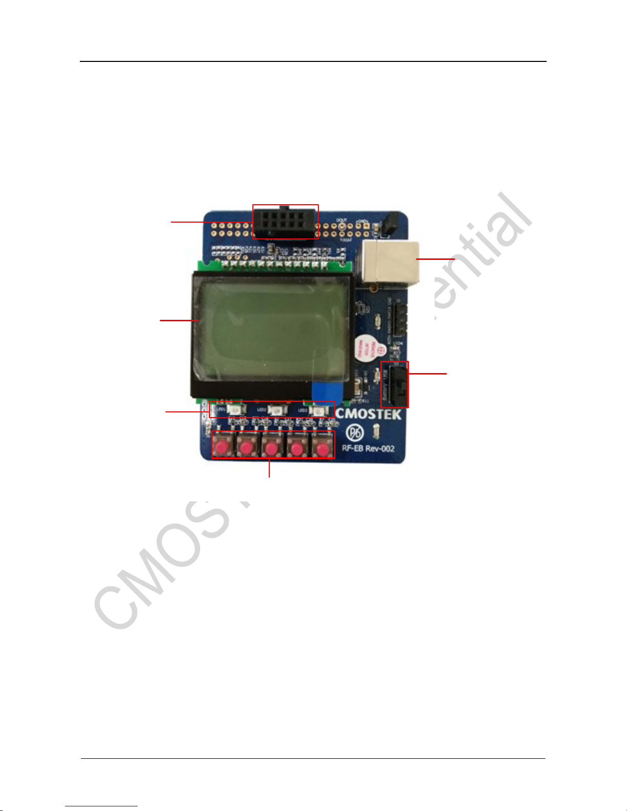
The main components of the evaluation motherboard are as shown in figure 1.
模块连接头
LCD
LED
按键
电源开关
USB插座
Figure1. Evaluation Motherboard
1. Module Connector (EM-Connector) – The module connector is a 10 pins, 2.54mm female connector,
mainly connecting the evaluation motherboard and the wireless module.
2. LED –There are 3 LEDs on the evaluation motherboard, indicating the working state of the evaluation
motherboard.
LED1 –Blinking once indicates that the RF-EB has successfully transmitted one packet.
LED2 –Blinking once indicates that the RF-EB has successfully received one packet.
LED3 –Blinking once indicates that the RF-EB failed to transmit or receive one packet.
3. Power Switch - The power switch (S3) determines the power supply of the RF-EB. When the power
switch is switched to 'USB', the RF-EB voltage is supplied by the USB socket. When the power switch is
switched to 'Battery', the RF-EB voltage is supplied by the battery.
AN148
Rev 0.8 | Page 4/13
www.cmostek.com
4. USB Socket –The USB socket connects the RF-EB with the PC, powering for the RF-EB.
5. LCD –RF-EB has a 128X64 pixels LCD, used for the wireless module configuration information display
and the feature performance demonstration.
6. Button–RF-EB has five buttons (K1-K5). The user can configure the wireless module according to the
information provided by the LCD.
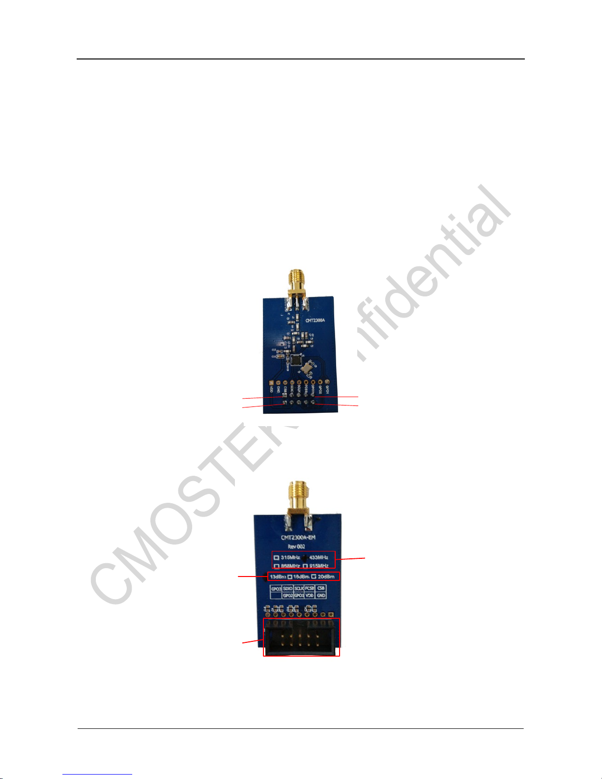
1.2 Wireless Module (CMT2300AW-EM)
CMT2300AW-EM is the evaluation module of the wireless transceiver chip CMT2300AW provided by
CMOSTEK. It consists of the simple peripheral circuit, the matching network and the CMT2300AW chip. The
top and bottom view of CMT2300AW-EM are shown below. The pins are defined as shown in the following
table.
1
2
9
10
Figure2. CMT2300AW-EM Top View
模块连接头
模块类型
模块频段
Figure3. CMT2300AW-EM Bottom View
 Loading...