

CMOSTEK CMT2150A, CMT2250A, CMT2251A-EM, CMT2251A, CMT2150A-EM User Manual
...
AN113
Rev 1.0 | Page 1 / 34
www.cmostek.com
AN113
CMT2150A/2250(1)A One-Way RF Link Development Kits User’s Guide
Introduction
The purpose of this docum ent is to provide the guidelines f or the users to use the CMT2150A/2250(1)A One-Way RF Link
Development Kit s ( Devel opment K it s) in different applicati on s chemes . The r elat ed p art number s cover ed by t his doc ument is
shown in table below.
Table 1. Part Numbers Covered in this Document
Part Number Description
CMT2150A
CMT2250A
CMT2251A
The Development Kits are a set of the hardware and software tools designed to help the users to easily evaluate the
performance and demonstrate the features of products CMT2150A, CMT2250A and CMT2251A. These devices are part of the
CMOSTEK Microelectronics Co., Ltd. (CMOSTEK) NextGenRF
receivers and transceivers. They are optimized for the low system cost, low power consumption, battery-pow ered one-way RF
link applicat ion with their highly integrated and low power design .
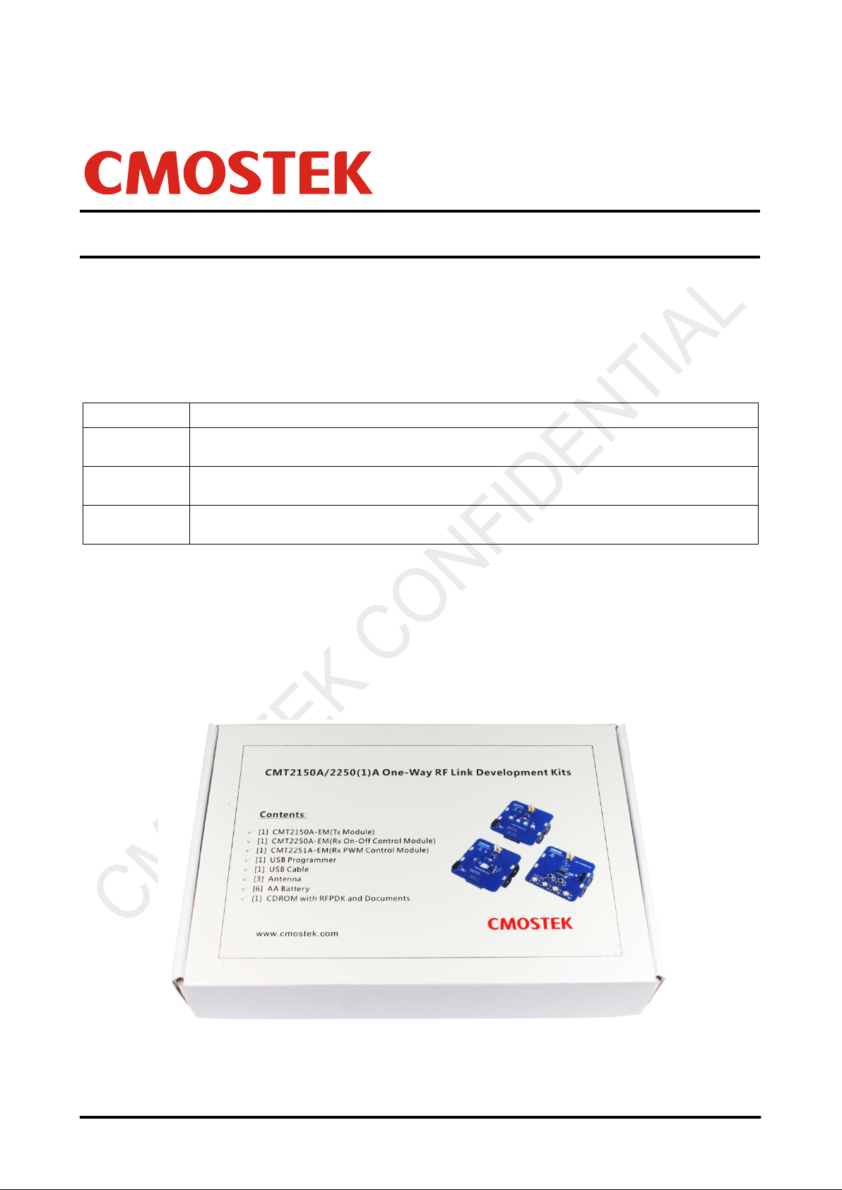
The package of the Development Kits is shown i n Figure 1.
True single-chip, highly flexible, high performanc e, OOK RF transmitter with embedded d ata encoder
ideal for 240 to 480 MHz w ireless applications
True single-chip, ultra low power and high perf ormance device t hat consists of an OOK RF recei ver, a
data decoder and 4 data output pins for various 300 to 480 MHz wireless applications
True single-chip, ultra low power and hi gh performance devi ce that consi sts of an OOK RF receiver , a
data decoder and 1 PWM output pin for various 300 to 480 MHz wireless appl ications.
TM
family, which includes a complete line of transmitters,
Copyright © By CMOSTEK
Figure 1. CMT2150A/2250(1)A One-Way RF Link Development Kits

AN113
Rev 1.0 | Page 2 / 34
www.cmostek.com
Table of Contents
1. Development Kits Contents ........................................................................................................................................ 4
2. Application Schemes .................................................................................................................................................. 6
2.1 LED On/Off............................................................................................................................................................ 7
2.2 Pulse ..................................................................................................................................................................... 8
2.3 Periodic Tx .......................................................................................................................................................... 10
2.4 PWM ................................................................................................................................................................... 12
2.5 Normal ................................................................................................................................................................ 14
3. CMT2150A-EM ............................................................................................................................................................ 17
4. CMT2250A-EM ............................................................................................................................................................ 19
5. CMT2251A-EM ............................................................................................................................................................ 21
6. USB Programmer ....................................................................................................................................................... 23
6.1 EM-Connector ..................................................................................................................................................... 23
6.2 LED Indicators ..................................................................................................................................................... 23
6.3 USB Socket ......................................................................................................................................................... 24
7. RFPDK ........................................................................................................................................................................ 25
7.1 Installation Steps ................................................................................................................................................. 25
7.2 Starting the RFPDK ............................................................................................................................................. 25
7.3 Device Control Panel .......................................................................................................................................... 27
7.3.1 Basic Mode and Advanced Mode............................................................................................................. 27
7.3.2 Configuration List and Chip Parameters .................................................................................................. 27
7.3.3 List, Export and Burn ............................................................................................................................... 27
7.3.4 Status and Notice..................................................................................................................................... 28
7.4 Burn Log.............................................................................................................................................................. 28
7.5 Read Device ........................................................................................................................................................ 29
8. Frequently Asked Questions .................................................................................................................................... 30
9. Document Change List.............................................................................................................................................. 31
10. Appendix: CMT2150A-EM and CMT2250(1)A-EM Schematics ............................................................................... 32
11. Contact Information .................................................................................................................................................. 34

Rev 1.0 | Page 3 / 34
www.cmostek.com
API
PCB
CDROM
PWM
Err
RFPDK
ksps
Tx
OOK
USB
Abbreviations
Abbreviations used in this document are described below.
AN Application Notes PC Personal Computer
Application Programming Interface
BOM Bill of Materi als PER Packet Err or Rate
Compact Disk Read O nly Memory
EM Evaluation Module(s) RF Radio Fr equency
Error
ID Identification Rx Receiving, Receiver
Kilo Symbols Per Second
LED Light Emitting Diode SR Symbol Rate
On-Off Keying
PA Power Amplifier
Printed Circuit Board
Pulse Width Modulation
RF Products Development Kit
Transmission, Transmitter
Universal Serial Bus
AN113
AN113
Rev 1.0 | Page 4 / 34
www.cmostek.com
1. Development Kits Contents
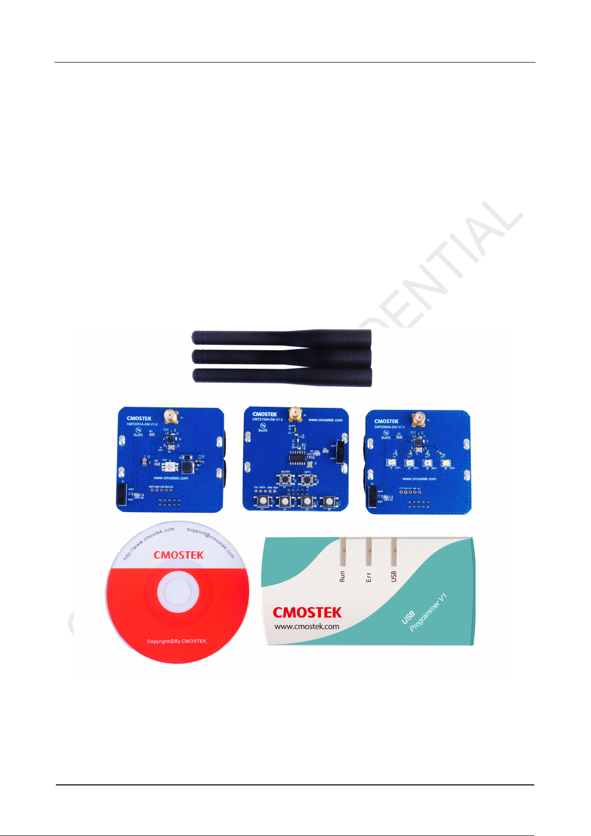
The Development Kit s contain the following c om ponents:
1 x CMT2150A-EM V1.0 Tx modul e
1 x CMT2250A-EM V1.0 Rx on-off control module
1 x CMT2251A-EM V1.0 Rx PWM control module
1 x USB Programmer V1
1 x CDROM with RFPDK i nstaller and documents
1 x USB Cable
6 x AA Batteries
3 x Antennas
Please note that t he CMT21 50A-EM is by default configur ed to work in pair with CM T2250A-E M. U sing t he RFPDK, t he us er
can easily program the PWM function into the CMT2150 A, so that it can work in pair with CMT2251A-EM. Please refer to
“Chapter 2 Application Schemes” for the detail of the configuration.
Figure 2. Development Kits Contents
Rev 1.0 | Page 5 / 34
www.cmostek.com
Off control feature, and work in pair with
CMT2150A-EM
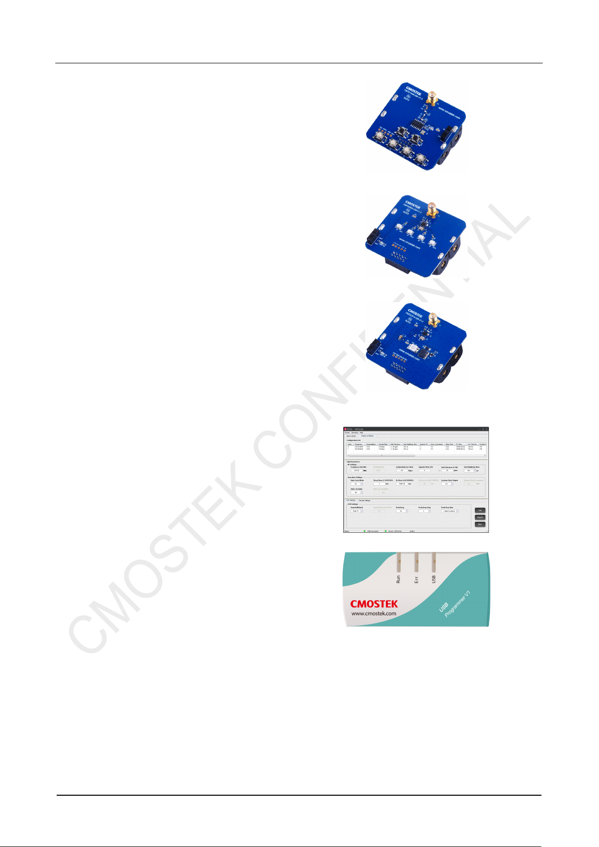
The CMT2150A-EM is the Tx evaluat ion module, it can be
used to work in pair with CMT2250A-EM to demonstrate
the OnCMT2251-EM to demons trate the PWM control feature.
CMT2250A-EM
The CMT2250A-EM is the On-Off control Rx evaluation
module. The user can use it to evaluate the CMT2250A
On-Off control feature.
CMT2251A-EM
AN113
The CMT2251A-EM is the PWM control Rx evaluation
module. The user can use it to evaluate the CMT2251A
PWM control feature.
RFPDK
CMOSTEK provides the PC application that allows the
users to confi gure all the product features to CMOSTEK
NextGenRF
installation pack can be found on the CDROM of the
CMT2150A/2250(1)A One-Way RF Link Development Kits.
TM
products in the most intuitional way. The
USB Programme r
It transmits data between the EM and the PC via two
interfaces: USB t o PC and s eri al port to E M. T he prot oc ols
of the serial por t differ f or different parts (c hips). The USB
programmer automatically identifies the part on the EM
once it is connect ed, and t h en u ses t he des ir ed prot oc ol t o
communicate to t he part.
AN113
Rev 1.0 | Page 6 / 34
www.cmostek.com
Pulse manner
PWM signal generated by the CMT2251A
2. Application Schemes
In order to help to us er to star t using the Dev elopment K its easi ly, CMOSTEK has defined a f ew confi gurations with different
application sc hemes on the RFPDK. The user only needs to follow the guideli nes in the subs ections of t his chapter, program
the configuration to the corresponding evaluation modules and start the evaluation. The appli cat ion sc hemes ar e lis ted in t he
tables below with the different modules required.
Table 2. Application Schemes for CMT2150A-EM in Pair with CMT2250A-EM
Application
Schemes
LED On/Off
Pulse
Periodic Tx
CMT2150A CMT2250A
Basic/Advanced Index Basic/Advanced Index
Basic 1 Basic 1
Basic 2 Basic 2
Advanced 1 Advanced 1
Description
To control the LEDs on CM T2250A-EM in On/Off
manner
To control the LEDs on CM T2250A-EM in Short
Periodic transmission from CMT2150A-EM to
CMT2250A-EM
Table 3. Application Scheme for CMT2150A-EM in Pair with CMT2251A-EM
Application
Schemes
PWM
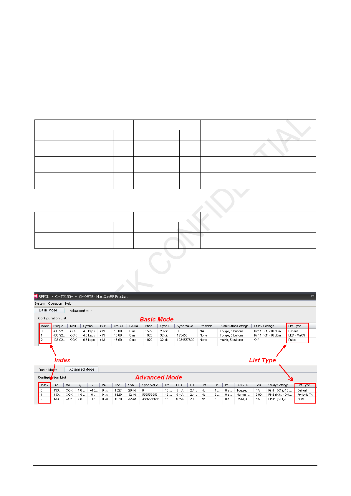
The configurations of each appl icat ion schem e are by default provide d on the RFPD K. The In dex number is shown i n the 1
(left) column of the configur ation lis t, while t he name of the applicati on list (also called “List Type”) is shown in the last (ri ght)
column. An example of the CMT2150A configurat ion lists in Basic / Advanc ed modes are shown in the figures below.
CMT2150A CMT2251A
Basic/Advanced Index Basic/Advanced Index
Advanced 2 Advanced 1
Description
To control the LED on the CMT2251A-EM with
st
After selecting and program ming the application sc heme into the devices, the corr esponding functions can be imm ediately
demonstrated. Thos e functions are introduced in the below sub-sections.
Figure 3. Configuration Lists of the CMT2150A
AN113
Rev 1.0 | Page 7 / 34
www.cmostek.com
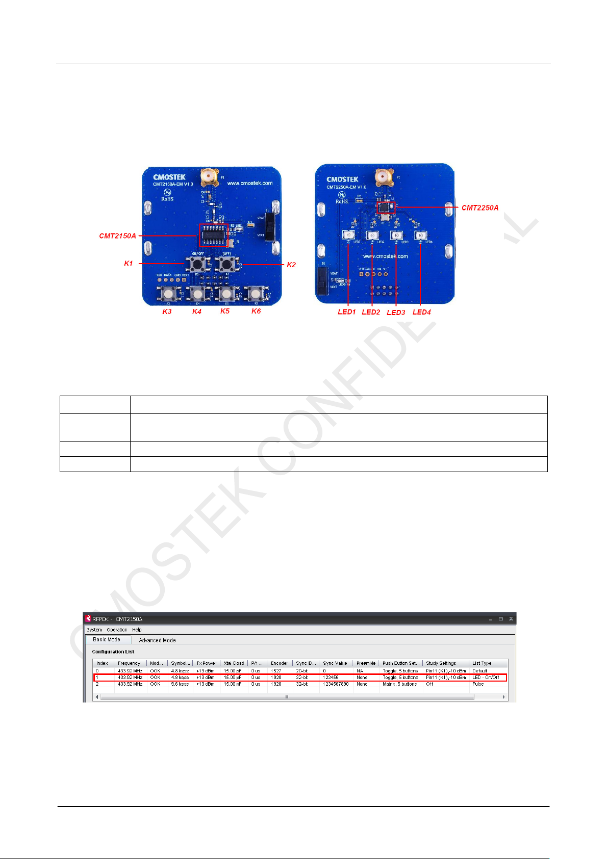
2.1 LED On/Off
In the LED On/Off scheme, the user can experi enc e to pus h but t ons on the transmitter module to turn on and off t he LEDs on
the receiver module. Pus h buttons on the CMT2150A-EM and t he 4 LEDs on CMT2250A-EM are shown and descr ibed as
below.
Figure 4. EMs Used to Experience LED On/Off Scheme
Table 4. Push Buttons Functions Definition of LED On/Off Scheme
Push Button Function Description
K1
K2 Not us ed. It could be used as Off button if the On/Off button(s) is set as “Separated” on the RFPDK.
K3, K4, K5, K6 Turn on and off the LED1, LED2, LE D 3 and LED4 on CMT2250A-EM respectively.
The user can follow bel ow instructions to experience the LED On/Off scheme.
1. Instal l the lat est RFPD K on the PC (r efer t o “Sect ion 7. 1 I nst al lation S teps ”) and c onnec t t he USB pr ogr ammer to t he PC
with a USB cable, t hen start the RFPDK on the PC.
2. Connect the CMT2150A-EM to the USB Programmer with EM-Connector, select CMT2150A on the RFPDK, stay in Basic
Mode, select the LED On/Off scheme on the configuration list, as shown in figure bel ow , and burn the configuration to the
CMT2150A-EM.
Global On/Off cont rol button, turns on or off the 4 LEDs on CMT2250A-EM . Press K1 more than for 5
seconds will send out the study packet.
3. Repeat step 2 to burn the LED On/Off configuration to the CM T 2250A-EM on the RFPDK
Figure 5. Selecting the LED On/Off Configuration of CMT2150A
AN113
Rev 1.0 | Page 8 / 34
www.cmostek.com
Figure 6. Selecting the LED On/Off Configuration of CMT2250A
4. After both of the modules are programmed done successfully, the user can start evaluate the LED On/O ff control scheme.
A few key parameters settings in this application scheme are:
Frequency = 433.92 MHz
Symbol Rate = 4.8 ksps
Encoder = 1920
Push Button Setting = Toggle, 5 buttons
Study Function = on
Study Button = Pin11 (K1)
Notes:
1. Please r efer to the “AN112 CMT215 0A Configurat ion Guideline ” for the introducti on of Toggle mode of the push but ton
setting and the 1920 encoding format.
2. The study f unction is enabled in this sc heme, while the Sync ID on bot h of the Tx and Rx side are set to the sam e by
default. In order t o experience the st udy function, the user should s et the Sync ID to the di fferent values bef ore burning
the configurati ons to the Tx and Rx devices. Pin11 (K1) is assigned as the study button in Periodic Tx scheme.
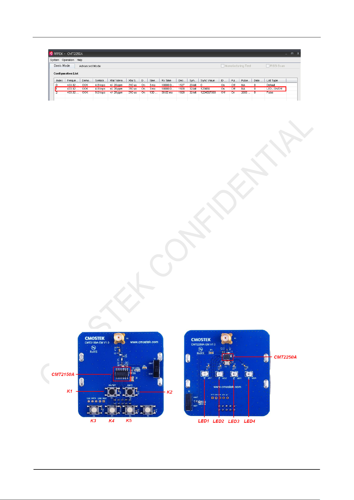
2.2 Pulse
In the Pulse scheme, the user can experienc e to push butto ns on the tr ansmitter module to turn on and of f the LEDs on the
receiver module. Each time an instruction is issued by pr essing t he button(s ), t he corresponding LEDs will only be turned on
for 2 seconds and then automatically swit ched off. The push buttons are shown and described in the figure/table below:
Figure 7. EMs Used to Experience Pulse Scheme
AN113
Rev 1.0 | Page 9 / 34
www.cmostek.com
Table 5. Push Buttons Functions Definition of Pulse Scheme
Push Button Function Description
K1, K2,K3, K4, K5
K6 Not us ed in this scheme
The user can follow bel ow instructions to exper ience the Pulse scheme.
1. Instal l the lat est RFPD K on the PC (r efer t o “Sect ion 7. 1 I nst al lation S teps ”) and c onnec t t he USB pr ogr ammer to t he PC
with a USB cable, then start the RFPDK on the PC.
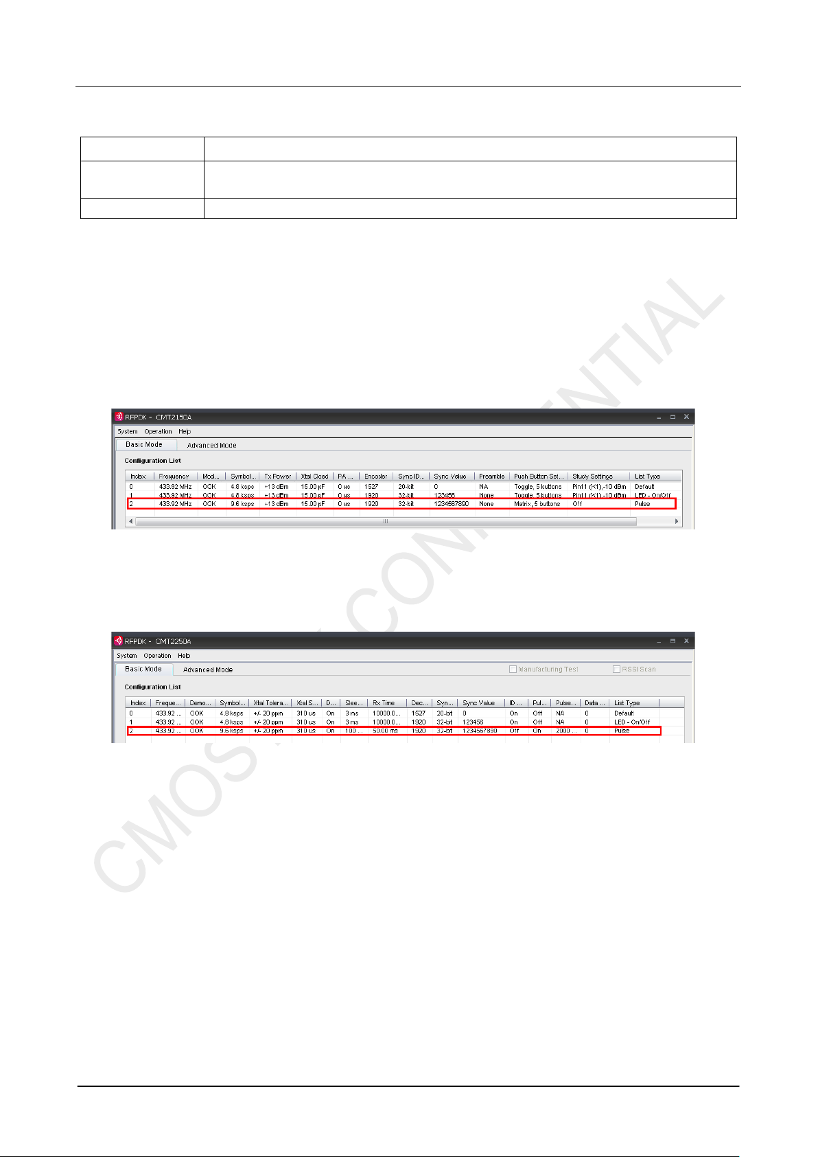
2. Connect the CMT2150A-EM to the USB Programmer with EM-Connector, select CMT2150A on the RFPDK, stay in Basic
Mode, select the Pul s e c onfi gurat i on on th e c onfi gur ati on li s t, as s hown in f i gure b el ow, an d burn the configuration t o th e
CMT2150A-EM.
Turn on the LED(s) on the CMT225 0A-EM for 2 seconds in the manner s hown in Table 6, and then
the LED(s) will be switched off automatic ally.
Figure 8. Selecting the Pulse Configuration o f CMT2150A
3. Repeat step 2 to burn the Pulse conf iguration to the CMT2250A-EM on the RFPDK
Figure 9. Selecting the Pulse Configuration o f CMT2250A
4. After the programming is done, the user can start to use the evaluation modules in Pulse scheme.
In this scheme, pus h button K1-K5 are used t o control the LED1-4 wi th the mapping rule sho wn in the table below, K 6 is
unused in this scheme.
 Loading...