

CMOSTEK CMT2219B User Manual

AN166
Rev0.7 | 1/8
www.cmostek.com
Overview
This document discusses RSSI related registers and their usage as well as the calibration methods of the CMT2219B.
The product models covered in this document are shown in the below table.
Table 1. Product Models Covered in the Document
Product Model
Frequency Range
Modulation Type
Main Function
Configuration Mode
Packaging
CMT2219B
127 - 1020 MHz
(G)FSK/OOK
Receiver
Register
QFN16
Before reading this document, it is recommended to read the AN161-CMT2219B Quick Start Guide to understand the
basic information of the CMT2219B.
AN166
CMT2219B RSSI User Guide
Copyright © By CMOSTEK

AN166
Rev0.7 | 2/8
www.cmostek.com
Table of Contents
1 RSSI Measurement and Comparison .............................................................................................. 3
1.1 RSSI Measurement Related Registers ............................................................................................................... 3
1.2 RSSI Measurement and Comparison in FSK mode ........................................................................................... 4
1.3 RSSI Measurement and Comparison in OOK Mode .......................................................................................... 5
1.4 RSSI Measurement Result Compensation ......................................................................................................... 6
2 Revise History ................................................................................................................................... 7
3 Contacts ............................................................................................................................................. 8
AN166
Rev0.7 | 3/8
www.cmostek.com
1 RSSI Measurement and Comparison
The purpose of RSSI measurement is to help users get the accurate value of the currently received signal strength. The
measurement value of the RSSI of a received signal can be regarded to some extent as the equivalence of the communication
distance at a constant transmission power.
In the procedure of RSSI comparison, it compares the current real-time RSSI value to a threshold to generate a signal indicating
whether the RSSI is valid. This indication signal can be mapped to the RSSI_VLD interrupt for application usage or sent to the
chip to implement super-low power (SLP) receiver.
1.1 RSSI Measurement Related Registers
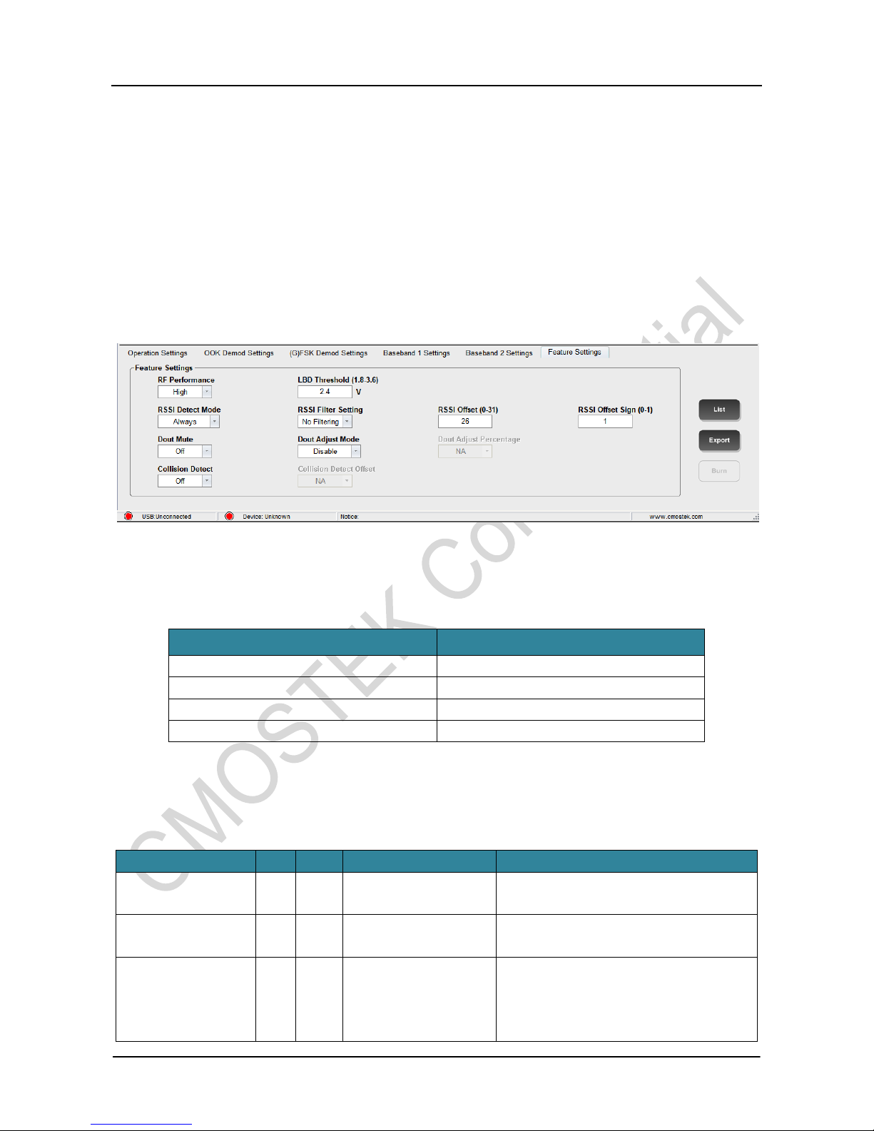
The corresponding RFPDK UI screen and parameters are shown in the below figure.
Figure 1. RFPDK UI Screen and Parameters for RSSI
Table 2. RSSI Related Bit Flags
Register Bit Flag for RFPDK
Register Bits
RSSI offset sign
RSSI_OFFSET_SIGN
RSSI offset
RSSI_OFFSET<4:0>
RSSI detection mode
RSSI_DET_SEL<1:0>
RSSI filter setting
RSSI_AVG_MODE<2:0>
See the below table for the register descriptions.
Table 3. Registers in Configuration Area
Name
Bits
R/W
Bit Flag
Description
CUS_CMT9 (0x08)
7
RW
RSSI_OFFSET_SIGN
The sign bit of the error compensation value for
RSSI measurement.
CUS_RSSI (0x0B)
7:3
RW
RSSI_OFFSET<4:0>
Error compensation value for RSSI
measurement.
CUS_SYS11 (0x16)
4:3
RW
RSSI_DET_SEL<1:0>
RSSI measurement time.
0: measure continuously
1: measure when PREAM_OK is active
2: measure when SYNC_OK is active
 Loading...