

CMOSTEK CMT2300A, CMT2119B, CMT2219B User Manual
AN199
Rev0.7 | 1/8
www.cmostek.com
Product Model
Frequency Range
Modulation Type
Main Function
Configuration Mode
Packaging
CMT2300A
126.33 - 1020 MHz
(G)FSK/OOK
Transceiver
Register
QFN16
CMT2119B
126.33 - 1020 MHz
(G)FSK/OOK
Transmitter
Register
QFN16
CMT2219B
126.33 - 1020 MHz
(G)FSK/OOK
Receiver
Register
QFN16
AN199
CMT2300A/CMT2119B/CMT2219B RF Frequency Calculation Guide
Copyright © By CMOSTEK
Overview
This document discusses the RF frequency calculation formula for CMT2300A / CMT2119B / CMT2219B, which helps on further
design and application based on the products.
The product models covered in this document are shown in the below table.
Table 1. Product Models Covered in This Document
Before reading this document, it is recommended to read the AN142-CMT2300A Quick Start Guide, AN184-CMT2119B Quick
Start Guide and AN161-CMT2219B Quick Start Guide to understand the basic information of the 3 products.

AN199
Rev0.7 | 2/8
www.cmostek.com
Table of Contents
1 RF Frequency Calculation.................................................................................................................3
1.1 Configuring RF Parameters of RX ...................................................................................................................... 3
1.2 Configuring RF Parameters of TX ...................................................................................................................... 6
2 Revise History ....................................................................................................................................7
3 Contacts ..............................................................................................................................................8
AN199
Rev0.7 | 3/8
www.cmostek.com
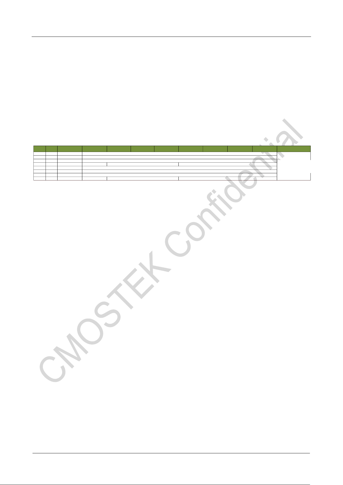
Addr R/W Name Bit 7 Bit 6 Bit 5 Bit 4 Bit 3 Bit 2 Bit 1 Bit 0 Function
0x18 RW CUS_RF1
0x19 RW CUS_RF2
0x1A RW CUS_RF3
0x1B RW CUS_RF4 FREQ_PALDO_SEL
0x1C RW CUS_RF5
0x1D RW CUS_RF6
0x1E RW CUS_RF7
0x1F RW CUS_RF8 FSK_SWT
频率区
FREQ_TX_N [7:0]
FREQ_TX_K [7:0]
FREQ_TX_K [15:8]
FREQ_VCO_BANK [2:0] (000)
FREQ_TX_K [19:16]
FREQ_RX_N [7:0]
FREQ_RX_K [7:0]
FREQ_RX_K [15:8]
FREQ_DIVX_CODE [2:0]
FREQ_RX_K [19:16]
Frequency Area
1 RF Frequency Calculation
The RF frequency calculation and manual configuration methods for the 3 products are described below. Note that the
description of RX part is not applicable to the CMT2119B and the statement of TX part is not applicable to the CMT2219B.
In general, when configuring RF frequency, it's recommended for users to generate parameters using RFPDK and write them to
the registers in the frequency area. If users need to configure the frequency of TX and RX separately in applications while not
using the fast frequency hopping mechanism, it's required for users to know the detail information of the register configuration
and related value calculation. The registers in the frequency area are listed in the below table.
Table 2. Registers in Frequency Area
In the table, the value of FSK_SWT is generated by RFPDK, with no depending on frequency. Do not change this value when
configuring other bits of the register.
1.1 Configuring RF Parameters of RX
To configure the frequency of RX, the below items need to be configured.
FREQ_VCO_BANK <2:0>
FREQ_DIVX_CODE <2:0>
FREQ_RX_N <7:0>
FREQ_RX_K <19:0>
AFC_OVF_TH <7:0>
Among them, N is the integer part of the frequency word, K is the fractional part of the frequency word, DIVX CODE is used to
select the division factor of the PLL, and VCO BANK is used to select the operating frequency range of the VCO. The calculation
is as follows.
First, check the table to get the value of FREQ_VCO_BANK<2:0> and FREQ_DIVX_CODE<2:0> (both need to be written to the
registers) and DIVIDER (frequency dividing factor, used to calculate N and K) according to the target frequency band where the
configured frequency is located.
 Loading...