

CMOSTEK CMT2110A, CMT2210A User Manual
AN103
Rev 1.0 | Page 1 / 23
www.cmostek.com
AN103
CMT2110A/2210A One -Way RF Link Development Kits User’s Guide
Introduction
CMT2110A/2210A One-Way RF Link Development Kits (Development Kits) are a set of the hardware and
software tools designed to help the users to easily evaluate the performance and demonstrate the features of
products CMT2110A and CMT2210A. These two devices are part of the CMOSTEK Microelectronics Co., Ltd.
TM
(CMOSTEK) NextGenRF
CMT2110A is an ultra low-cost, highly flexible, high performance, single-chip OOK transmitter for various 240 to
480 MHz wireless applications. The CMT2210A is an ultra low-cost, highly flexible, high performance, single-chip
OOK receiver for various 300 to 480 MHz wireless applications. These two devices are optimized for the low
system cost, low power consumption, battery-powered one-way RF link application with their highly integrated
and low power design.
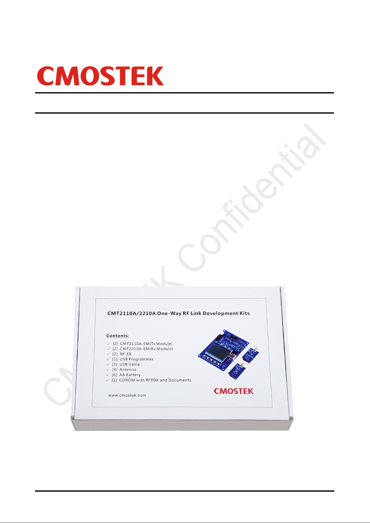
The Development Kits c ontain the components of two evaluation boards named RF-EB, a Tx evaluation module
named CMT2110A-EM, an Rx evaluation module named CMT2210A-EM, a USB Programmer and a PC
application named RFPDK (RF Products Development Kit). The package of the Development Kits is shown in
Figure 1.
family, which include a complete line of transmitters, receivers and transceivers. The
Copyright © By CMOSTEK
Figure 1. CMT2110A/2210A One-Way RF Link Development Kits

AN103
Rev 1.0 | Page 2 / 23
www.cmostek.com
Table of Cont e nt s
1. Development Kits Contents ........................................................................................................................ 4
Application Schemes .................................................................................................................................. 6
2.
Evaluation Scheme ................................................................................................................................ 6
2.1
2.2
Configuration Scheme ........................................................................................................................... 6
CMT2110A-EM .............................................................................................................................................. 8
3.
CMT2210A-EM .............................................................................................................................................. 9
4.
RF-EB .......................................................................................................................................................... 10
5.
Main Components ................................................................................................................................ 10
5.1
5.2
LCD Functional Icons ........................................................................................................................... 11
USB Programmer ....................................................................................................................................... 13
6.
EM-Connector ...................................................................................................................................... 13
6.1
6.2
LED Indicators ..................................................................................................................................... 13
6.3
USB Socket .......................................................................................................................................... 14
RFPDK ........................................................................................................................................................ 15
7.
Installation Steps .................................................................................................................................. 15
7.1
7.2
Starting the RFPDK ............................................................................................................................. 15
7.3
Device Control Panel ........................................................................................................................... 17
7.3.1
Basic Mode and Advanced Mode ............................................................................................. 17
7.3.2 Configuration List and Chip Parameters .................................................................................. 17
7.3.3
List, Export and Burn ................................................................................................................ 17
7.3.4
Status and Notice ..................................................................................................................... 18
7.4
Burn Log .............................................................................................................................................. 18
7.5
Read Device ........................................................................................................................................ 19
Frequently A ske d Questions .................................................................................................................... 20
8.
Document Change List ............................................................................................................................. 21
9.
Appendix: CMT2110A-EM and CMT2210A-EM Schematics .................................................................. 22
10.
Contact Information .................................................................................................................................. 23
11.

Rev 1.0 | Page 3 / 23
www.cmostek.com
Abbreviations
Abbreviations used in this document are described below.
AN
API
BOM
CDROM
EB
EM
Err
OOK
PA
Application Notes
Application Programming Interface
Bill of Materials
Compact Disk Read Only Memory
Evaluation Board
Evaluation Module(s)
Error
On-Off Keying
Power Amplifier
PC
PER
RF
RFPDK
Rx
Tx
SR
USB
AN103
Personal Computer
Packet Error Rate
Radio Frequency
RF Products Development Kit
Receiving, Receiver
Transmission, T ransm itter
Symbol Rate
Universal Serial Bus
Rev 1.0 | Page 4 / 23
www.cmostek.com
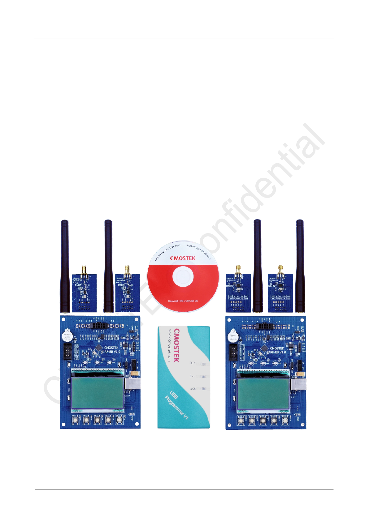
1. Development Kits Contents
The Development Kits contain the following components:
2 x RF-EB V1.0 evaluation boards
2 x CMT2110A-EM V1.0 Tx module
2 x CMT2210A-EM V1.0 Rx module
1 x USB Programmer V1
1 x CDROM with RFPDK installer and documents
1 x USB Cable
6 x AA Batt eries
4 x Antennas
AN103
Figure 2. Development Kits Contents
Rev 1.0 | Page 5 / 23
www.cmostek.com
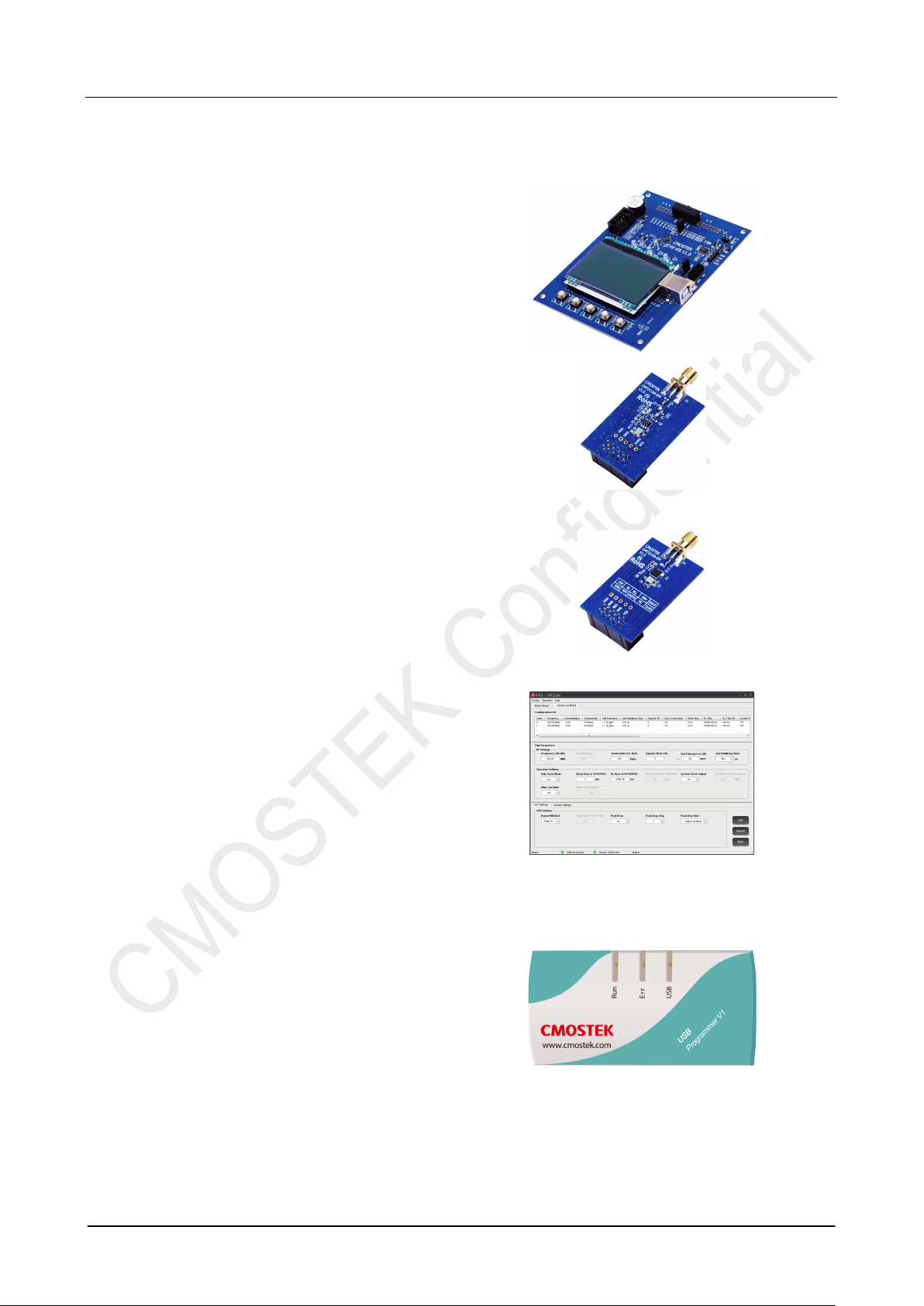
evaluation board for the
The user can use it to evaluate the CMT2110A
The user can use it to evaluate the CMT2210A
(chips). The USB programmer automatically
RF-EB
General purpose
CMOSTEK RF products. It can be used to evaluate
and demonstrate the main features of CMT2110A,
CMT2201A and other RF products.
CMT2110A-EM
The CMT2110A-EM is the Tx evaluation module.
performance and features.
AN103
CMT2210A-EM
The CMT2210A-EM is the Rx evaluation module.
performance and features.
RFPDK
CMOSTEK provides the PC application that allows
the users to configure all the product features to
TM
CMOSTEK NextGenRF
intuitional way. The installation pack can be found on
the CDROM of the CMT2110A/2210A One-Way RF
Link Development Kits.
products in the most
USB Programme r
It transmits data between the EM and the PC via two
interfaces: USB to PC and serial port to EM. The
protocols of the serial port differ for different parts
identifies the part on the EM once it is connected,
and then uses the desired protocol to communicate
to the part.

AN103
Rev 1.0 | Page 6 / 23
www.cmostek.com
2. Application Schemes
The Development Kits can be used in 2 different application schemes.
Evaluation Scheme:
Configuration Scheme:
2.1 Evaluation Scheme
The necessary components of the evaluation scheme are:
Two RF-EBs
CMT2110A-EM
CMT2210A-EM
Main product features can be evaluated and demonstrated in this scheme. Follow the step-by-step instructions to
start working in the Evaluation Scheme.
1. Turn off the RF-EB power switch (SW1, see Figure 6 in Page 10). It is always good practice to plug in or out
the evaluation modules after the RF-EB is powered off.
2. Switch the Power Mode Jumper (J7, see Figure 6 in Page 10) to the USB or BAT side to select the available
power supply source.
3. Plug the evaluation modules into both RF-EBs respectively. Please note that there are 2 sets of evaluation
modules and antennas, the user should pair them properly according to their frequency labeled on them.
4. Turn on the power switch (SW1) of the RF-EB. The LED indicator for the power supply indication will be light
up to show to “ON” status of the RF-EB.
5. Start to configure the evaluation modules according to the instructions displayed on the LCD and then
evaluate the main features/performance.
2.2 Configuration Scheme
The necessary components of the configuration scheme are:
RFPDK
USB Programmer
CMT2110A-EM or CMT2210-EM
This scheme allows the user to freely customize all product features and program them into the chips. Once the
programming is done successfully, the evaluation module is ready to be integrated into the user’s own application
systems. Moreover, the users can program chip configurations to their self-designed CMT2110A/2210A modules
as long as the programming interface is reserved.
Main product features can be configured and evaluated/demonstrated in this
scheme.
All product features of can be configured in this scheme.
 Loading...