

Page 1
DIGITAL VIDEO RECORDER
1
WARNING
This symbol is intended to alert the user to the presence of unprotected
“Dangerous voltage" within the product's enclosure that may be strong
enough to cause a risk of electric shock.
This symbol is intended to alert the user to the presence of
important operating and maintenance (servicing)
instructions in the literature accompanying the appliance.
WARNING
TO REDUCE THE RISK OF FIRE OR ELECTRIC SHOCK, DO NOT EXPOSE THIS
APPLIANCE TO RAIN OR MOISTURE.
NOTE: This equipment has been tested and found to comply with the limits for a class
digital device, pursuant to part 15 of the FCC Rules. These limits are designed to provide
reasonable protection against harmful interference when the equipment is operated in a
commercial environment. This equipment generates, uses, and can radiate radio frequency
energy and, if not installed and used in accordance with the instruction manual, may cause
harmful interference to radio communications. Operation of this equipment in a residential
area is likely to cause harmful interference in which case the user will be required to correct
the interference at his own expense.
Disposal of Old Electrical & Electronic Equipment
(Applicable in the European Union and other European countries with separate
collection systems)
This symbol on the product or on its packaging indicates that this product shall not be treated as
household waste. Instead it shall be handed over to the applicable collection point for the recycling
of electrical and electronic equipment. By ensuring this product is disposed of correctly, you will
help prevent potential negative consequences for the environment and human health, which could
otherwise be caused by inappropriate waste handling of this product. The recycling of materials will
help to conserve natural resources. For more detailed information about recycling of this product,
please contact your local city office , your household waste disposal service or the shop where you
purchased the product.
Page 2

2
PRECAUTIO
N
• Make sure to switch the power off before you install the DVR.
• There is the danger of an electric shock if the DVR is opened by an unqualified service
engineer or installer.
• Avoid using the DVR outside of the reference temperature and humidity indicated in the
specification.
• Avoid exposing the DVR to violent movement or vibration.
• Do not use or store the DVR in direct sunlight or near to any source of heat.
• Do not place any object into the holes used for air circulation.
• Always use the DVR in a well ventilated location to prevent overheating.
• Risk of explosion if battery is replaced by an incorrect type.
• Dispose of used batteries according to the instructions.
• When the cooling fan is stopped, the below warning message will be displayed
at the monitor.
“ COOLING FAN IS STOPPED, TURN THE POWER OFF AND CHECK COOLING FAN”
In this case, do the power off right away and check the cooling fan working.
• The HDD is recommended to use enhanced IDE Hard Disc Drive type made by
Western Digital, Seagate, Hitachi and IBM, Samsung Electronics.
EXTERNAL HDD BAY (If specified as an accessory)
• Always attach the joining cable lead between the DVR and the HDD Bay for correct system
management. (Refer to the section describing the installation procedure for the EXTERNAL
HDD BAY)
• While the EXTERNAL HDD BAY is in operation never disconnect the power or connecting
cable. Before opening the top cover, you must turn off the power by the switch on the front
panel of the DVR. And then disconnect the power cord and other cables. Failure to follow
this procedure will result in lost data or malfunction of the system.
• When replacing any HDD always make certain that the replacement par t is fitt ed in the same
place and with the same connections as the original.
All the safety and operating instructions must be read before the unit is operated.
Page 3

DIGITAL VIDEO RECORDER
3
CONTENT
TABLE OF CONTENTS
1. FEATURE LIST ----------------------------------------------------------------------------------
2. PACKING DETAIL ------------------------------------------------------------------------------------------
3. LOCATION AND CONTROL -----------------------------------------------------------------
3.1 FRONT PANEL CONTROLS -------------------------------------------------------------------------------
3.2 REAR PANEL CONNECTORS -----------------------------------------------------------------------------
4. INSTALLATION ---------------------------------------------------------------------------------------------
4.1 TOTAL CONNECTION LAY-OUT -------------------------------------------------------------------------
4.2 INDIVIDUAL CONNECTION --------------------------------------------------------------------------------
4.2.1 CAMERA --------------------------------------------------------------------------------------------
4.2.2 AUDIO -----------------------------------------------------------------------------------------------
4.2.3 MONITOR -----------------------------------------------------------------------------------------------
4.2.4 EXTERNAL HDD BAY --------------------------------------------------------------------------
4.2.5 USB 2.0 Ports -------------------------------------------------------------------------------------
5. OPERATION --------------------------------------------------------------------------------------
5.1 FACTORY DEFAULT ----------------------------------------------------------------------------------
5.2 BUTTON CONTROLS ---------------------------------------------------------------------------
------
5.2.1 POWER ON / OFF ------------------------------------------------------------------------------
5.2.2 SCREEN DISPLAY ------------------------------------------------------------------------------
5.2.3 RECORD -------------------------------------------------------------------------------------------
5.2.4 SEARCH & PLAYBACK ------------------------------------------------------------------------
5.2.5 PLAY BUTTON INFORMATION --------------------------------------------------------------
5.2.6 DIGITAL ZOOM------------------------------------------------------------------------------------
5.2.7 SCREEN SELECT (LV/PB) ----------------------------------------------------------------------
5.2.8 SPOT MONITOR -----------------------------------------------------------------------------------
5.2.9 COPY ------------------------------------------------------------------------------------------------
5.2.10 DVR STATUS ------------------------------------------------------------------------------------
5.2.11 PTZ CONTROL ------------------------------------------------------------------------------------
5.2.12 FUNCTION BUTTON ---------------------------------------------------------------------------
5.2.13 AUDIO SELECT --------------------------------------------------------------------------------
5.2.14 PIP CONTROL ------------------------------------------------------------------------------------
5.3 REMOTE CONTROLLER ---------------------------------------------------------------------------
5.4 MOUSE CONTROL ---------------------------------------------------------------------------
-------
6. MENU SETUP ----------------------------------------------------------------------------------------------------
6.1 QUICK SETUP -----------------------------------------------------------------------------------------------
6.2 SCREEN ------------------------------------------------------------------------------------------------------
6.2.1 AUTO SEQUENCE ------------------------------------------------------------------------------
6.2.2 DISPLAY ---------------------------------------------------------------------------------------
6.2.3 TITLE -------------------------------------------------------------------------------------------
6.2.4 MULTI SCREEN ---------------------------------------------------------------------------------
6.2.5 COVERT ----------------------------------------------------------------------------------------------
6.2.6 SPOT ------------------------------------------------------------------------------------------------
6.2.7 CAMERA ------------------------------------------------------------------------------------------------
6
8
9
9
10
11
11
12
12
12
13
14
15
16
16
20
20
20
22
23
28
29
30
30
31
35
35
37
37
37
38
38
39
39
41
41
43
45
46
47
48
48
Page 4

4
CONTEN
T
6.3 RECORD ---------------------------------------------------------------------------------------------------------
6.3.1 RECORD SETUP -----------------------------------------------------------------------------------
6.3.2 RECORD PROGRAM -----------------------------------------------------------------------------
6.3.3 IMAGE QUALITY --------------------------------------------------------------------------------------
6.3.4 AUDIO RECORD -------------------------------------------------------------------------------------
6.3.5 REPEAT RECORD ---------------------------------------------------------------------------------
6.3.6 PLAY MODE -----------------------------------------------------------------------------------------
6.3.7 BACKUP MODE --------------------------------------------------------------------------------------
6.3.8 HOLIDAY -------------------------------------------------------------------------------------------------
6.4 EVENT ------------------------------------------------------------------------------------------------------------
6.4.1 MOTION DETECTION -----------------------------------------------------------------------------
6.4.2 EVENT SCREEN MODE -------------------------------------------------------------------------
6.4.3 EVENT CHECK --------------------------------------------------------------------------------------
6.4.4 EVENT MESSAGE ---------------------------------------------------------------------------------
6.4.5 EVENT MESSAGE RESET -----------------------------------------------------------------------
6.4.6 EVENT BUZZER ------------------------------------------------------------------------------------
6.4.7 SENSOR INPUT --------------------------------------------------------------------------------------
6.4.8 RELAY OUTPUT -------------------------------------------------------------------------------------
6.5 SYSTEM ---------------------------------------------------------------------------------------------------------
6.5.1 HDD -----------------------------------------------------------------------------------------------------
6.5.2 CLOCK ------------------------------------------------------------------------------------------------
6.5.3 VIDEO STANDARD ---------------------------------------------------------------------------------
6.5.4 LANGUAGE -------------------------------------------------------------------------------------------
6.5.5 REMOTE CONTROL ID ---------------------------------------------------------------------------
6.5.6 KEY SOUND --------------------------------------------------------------------------------------------
6.5.7 ADVANCE SETUP ---------------------------------------------------------------------------------
6.5.7.1 PASSWORD CHECK ---------------------------------------------------------------
6.5.7.4 DVR MENU SET -----------------------------------------------------------------------
6.5.8 FIRMWARE UPGRADE --------------------------------------------------------------------------
6.6 LINK ----------------------------------------------------------------------------------------------------------------
6.6.1 NETWORK --------------------------------------------------------------------------------------------
6.6.2 RS232C ------------------------------------------------------------------------------------------------
6.6.3 RS485 --------------------------------------------------------------------------------------------------
6.6.4 PTZ ------------------------------------------------------------------------------------------------------
6.6.5 E-MAIL --------------------------------------------------------------------------------------------------
6.7 SEARCH ----------------------------------------------------------------------------------------------------------
6.8 COPY -------------------------------------------------------------------------------------------------------------
6.9 EXIT ---------------------------------------------------------------------------------------------------------------
7. EXTERNAL TERMINAL INFORMATION -------------------------------------------------------
7.1~2 RS-485 / T.ADJ ---------------------------------------------------------------------------------------------
7.3~4 RELAYOUT / ALARM --------------------------------------------------------------------------------------
7.5~6 VGA / SERIAL ----------------------------------------------------------------------------------------------
7.7~8 ETHERNET/USB -------------------------------------------------------------------------------------------
8. SPECIFICATIONS -------------------------------------------------------------------------------
9. 256 CAMERA INTEGRATION SYSTEM --------------------------------------------------
49
49
50
56
57
58
58
58
59
60
60
61
61
61
61
62
62
63
64
64
66
67
68
68
68
68
69
69
71
72
72
75
75
76
76
79
79
80
81
81
82
83
84
85
88
Page 5

DIGITAL VIDEO RECORDER
5
CONTENT
10. HDD INSTALLATION ------------------------------------------------------------------------
10.1 INTERNAL HDD INSTALLATION -----------------------------------------------------------------------
10.2 DVD±RW(or CD-RW) installation-----------------------------------------------------------------------
11. NETWORK VIEWER --------------------------------------------------------------------------------------
11.1 SYSTEM REQUIREMENT --------------------------------------------------------------------------------
11.2 Be sure to setup THREE of files together when you execute the viewer program PC------
11.3 INSTALLING THE DVR VIEWER -----------------------------------------------------------------------
11.4 DVR VIEWER - LAYOUT ------------------------------------------------------------------------------------
11.5 DVR VIEWER - LIVE MODE -----------------------------------------------------------------------------
11.6 DVR VIEWER - PLAYBACK MODE -------------------------------------------------------------------
11.7 DVR PALYER - SETUP ------------------------------------------------------------------------------------
APPENDIX----------------------------------------------------------------------------------------------------------------
89
89
92
94
94
94
95
96
112
114
121
133
Page 6

6
FEATURE
S
Chapter 1 Features
Operation
Playback, recording, backup and transmission simultaneously
Real time single or multi-screen display
Pan & Tilt, 2X digital zoom and PIP display
Easy operation by IR remote controller, external keypad controller and USB 2.0 Mouse
Hidden camera option (covert)
User-friendly setup menu and operation
Playback
Multi-screen playback (Full/4/6/7/9/10/13/16 split)
Search by date, time and camera
Preview window on event search mode
Playback mode(frame/ field) setup
Recording
Select of the recording quality grade for each channel
Individual camera frame rate can be set by user
The recording speed of max. 120 images per second (NTSC)
Manual, schedule and event recording
Pre & Post-alarm recording
Select of the recording image size for each channel
4 channels audio recording
Select of the event mode for each channel
Network
Live and playback viewing
Remote control on a networked PC with the exclusive client viewer
(The viewer software is supplied for free.)
Flexible connections - 10/ 100 Mbps Ethernet/ ADSL
Up to 16 network users access simultaneously
Audio transmission between DVR and Client
Dynamic IP is available
Page 7

DIGITAL VIDEO RECORDER
7
FEATURES
External storage
Automatic backup to selected backup HDD (Event backup/ Mirroring)
Own external storage device to extend the HDD capacity
You can install 10 HDDs in 1 external HDD Bay and connect up to 4 Bay with this DVR.
(250GB X 40HDDs = 10TB, 500GB X 40HDD = 20TB, 1TB X 40HDD = 40TB)
Audio
4 channels audio recording in real time
Audio channel select for each channel
Copy
USB 2.0 external HDD
USB 2.0 memory stick
CD-R/ CD-RW/ DVD±RW/ DVD-RAM (optional)
General
Software downloading facility via network and USB memory stick
Auto detection of PAL / NTSC
Built-in software Watchdog
Automatic time adjustment through Network
VGA output for PC monitor(Optional)
Optional external CDRW or DVD±RW
Loop-through connections
Support of multiple Languages
Graphic User Interface for the MENU screen
Analog Spot
Page 8
8
PACKING DETAI
L
Chapter 2 Packing Detail
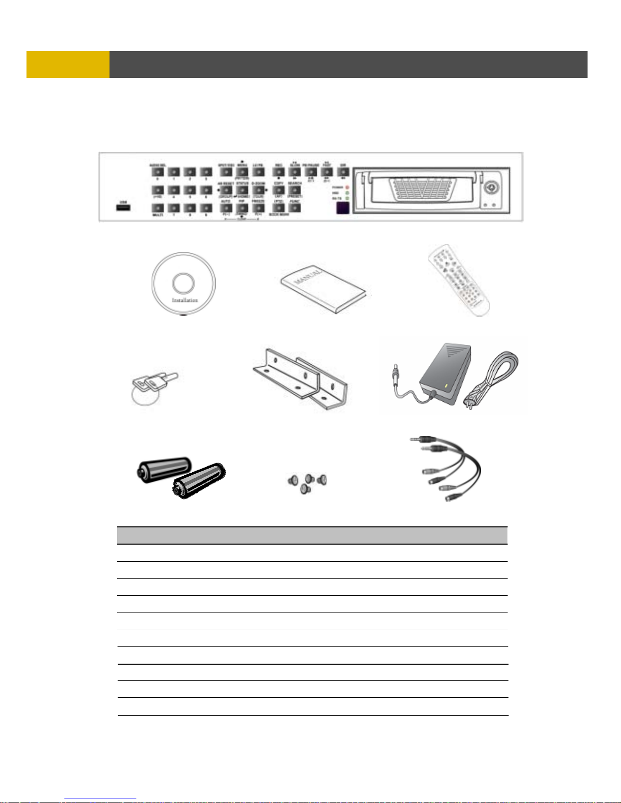
1. DVR
2. Network Viewer Program CD
3. User’s Manual
4. Remote Controller
5. R-HDD Rack Key
6. Rack Mounts
7. AC Adaptor & Power Cord
8. Batteries (For Remote Controller)
9. HDD Screws
10. Audio cable
4. Remote controller
3. User’s Manual
1. DVR
2. Network Viewer Program CD
5. R-HDD Rack Key
7. AC Adaptor & Power Cord
6 Rack Mounts
9. HDD Screws
8. Batteries
10. Audio cable
Page 9
DIGITAL VIDEO RECORDER
9
LOCATION AND CONTROL
Chapter 3 Location and Control
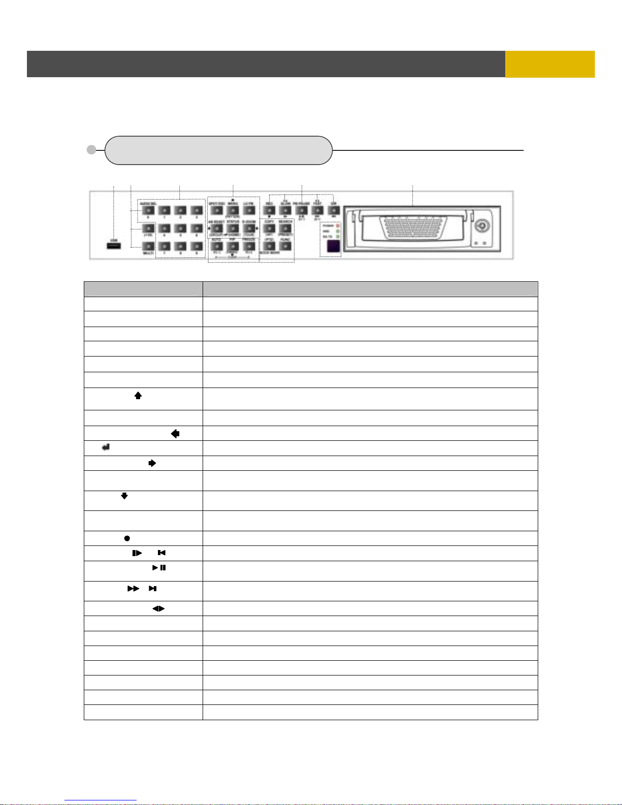
3.1 FRONT PANEL CONTROLS
Name Description
① USB USB 2.0 port to use a USB memory stick, Mouse or USB external devices
② CHANNEL SELECT
Buttons to select the camera or input the password
③ AUDIO SEL / 0
Audio select button / Button to select the camera or input the password
③ (+10) Button to select the camera(+10)+(0~6) 10/11/12/13/14/15/16
③ MULTI
Multi-channel select button
④ SPOT / ESC
Button to control spot monitor/ return to the previous menu/ Not use password
④ MENU /
Button to display the setup menu/ move to the upper direction
/ TILT up in PTZ mode
④ LV / PB
Button to convert the screen into real view mode or into playback mode
④ ALARM RESET /
Button to release the event signal/ move the left direction/ PAN left in PTZ mode
④ / STATUS/ ( HOME )
Button to enter the next step/ display the status/ return to home position in PTZ mode
④ D-ZOOM /
Button to control the digital zoom/ move to the right direction/ PAN right in PTZ mode
⑤ AUTO / F / ( - ) / A
Button to begin the auto sequence mode/ decrease the value/ focus in PTZ mode/
Button to set the section repetition playback
⑤ PIP / / CLEAR
Button to control PIP function/ move to the lower direction/ TILT down in PTZ mode/
Button to release the section repetition playback
⑤ FREEZE / F / ( + ) / B
Button freeze image/ increase the value/ focus in PTZ mode/ Button to set the section
repetition playback
⑥ REC( )
Button to begin and stop recording
⑥ SLOW( )/
Button to slow down the playback speed/ Backward playback button in pause mode
⑥ PB / PAUSE( )/ (Z-)
Button to start the playback. If press again, a still picture is displayed during
playback./ Zoom out of PTZ camera
⑥ FAST( )/ / (Z+)
Button to speed up the playback speed/ Forward playback button in pause mode/
Zoom in of PTZ camera
⑥ DIRECTION( )
Button to change the direction of playback/ Last Record backward playback
⑦ COPY(AF)
Button to display the copy menu/ automatically focus in PTZ mode
⑦ SEARCH(PRESET)
Button to display the search menu/ preset in PTZ mode
⑦ PTZ/ BOOKMARK Button to control PTZ camera/ Bookmark marking button
⑦ FUNCTION
Relay4 User action(FUNCTION + “+” / “-“)/ PTZ speed control
⑧ LED Display
Display of the status of power(POWER), HDD(HDD) and network(RX / TX)
⑧ Remote Sensor
Input sensor for the remote controller
⑨ R.HDD RACK
Removable HDD rack (Option: Built-in CD-RW or DVD±RW)
○
1
○
7
○
3
○
5
○
6
○4 ○
2
○
8
○
9
Page 10
10
LOCATION AND CONTRO
L
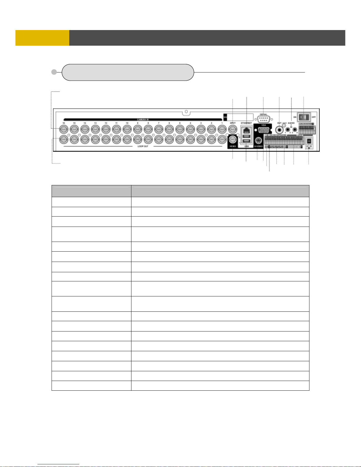
3.2 REAR PANEL CONNECTORS
Name Description
○
1
CAMERA IN
BNC input ports for cameras
○
2
CAMERA OUT
BNC output(looping) ports for cameras
○
3
SPOT
BNC output port for spot monitor
○
4
VIDEO OUT
BNC output port for the main monitor
(Same as the RCA video output of the front panel)
○
5
AUDIO IN
Stereo Jack input ports for an audio signal(4CH Line input)
○
6
AUDIO OUT
Stereo Jack output port for an audio signal
○
7
ETHERNET
Port for 10/ 100Mbps Ethernet/ xDSL
○
8
USB1 / USB2
USB 2.0 ports to use USB memory stick, Mouse or the external devices
○
9
VGA OUT
Output port for the VGA monitor
This DVR is compatible with TFT LCD monitor in PAL mode.
○
10
SERIAL
Connector for debugging. This DVR can be controlled by the other device
through this connector(RS-232C).
○
11
S-VIDEO OUT
Output port for the S-video output
○
12
GROUND
Earth ground port to connect with the external devices
○
13
RS-485
Terminal blocks of RS-485
○
14
T-ADJ
Input and output terminal blocks for time synchronization among DVRs
○
15
RELAY OUT
4 relay output terminal blocks
○
16
ALARM IN
Input terminal blocks for alarm signals
○
17
POWER IN
Socket for a 12V/6.67A power cord
○
18
POWER SWITCH
AC Power switch
○4
○
7
○
8
○
10
○
9
○
17
○14 ○16
○
6
○
12
○
13
○
11
○15
○1
○
2
○3 ○5
○18
Page 11
DIGITAL VIDEO RECORDER
11
INSTALLATION
Chapter 4 Installation
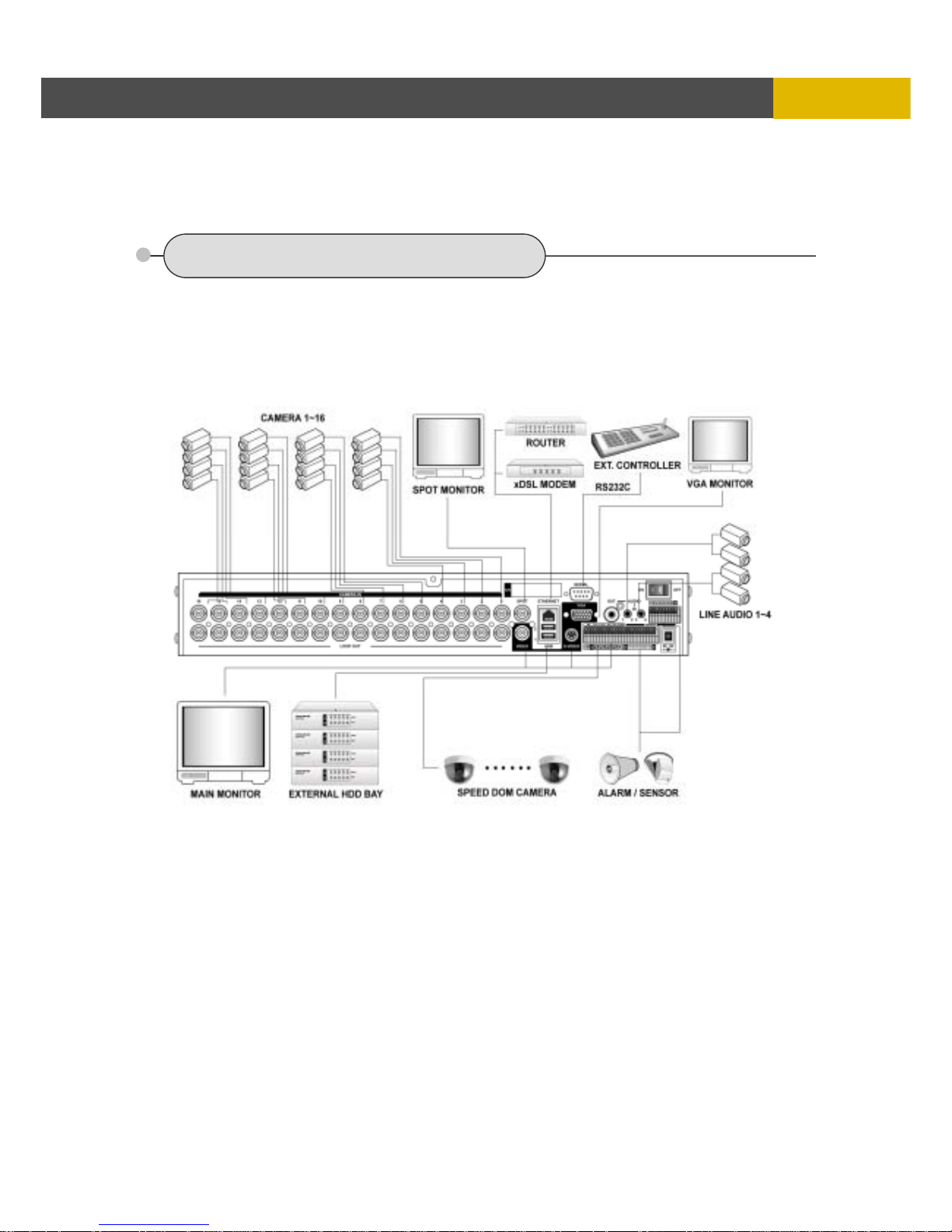
4.1 TOTAL CONNECTION LAY-OUT
Page 12
12
INSTALLATION
4.2 INDIVIDUAL CONNECTION
4.2.1 Camera
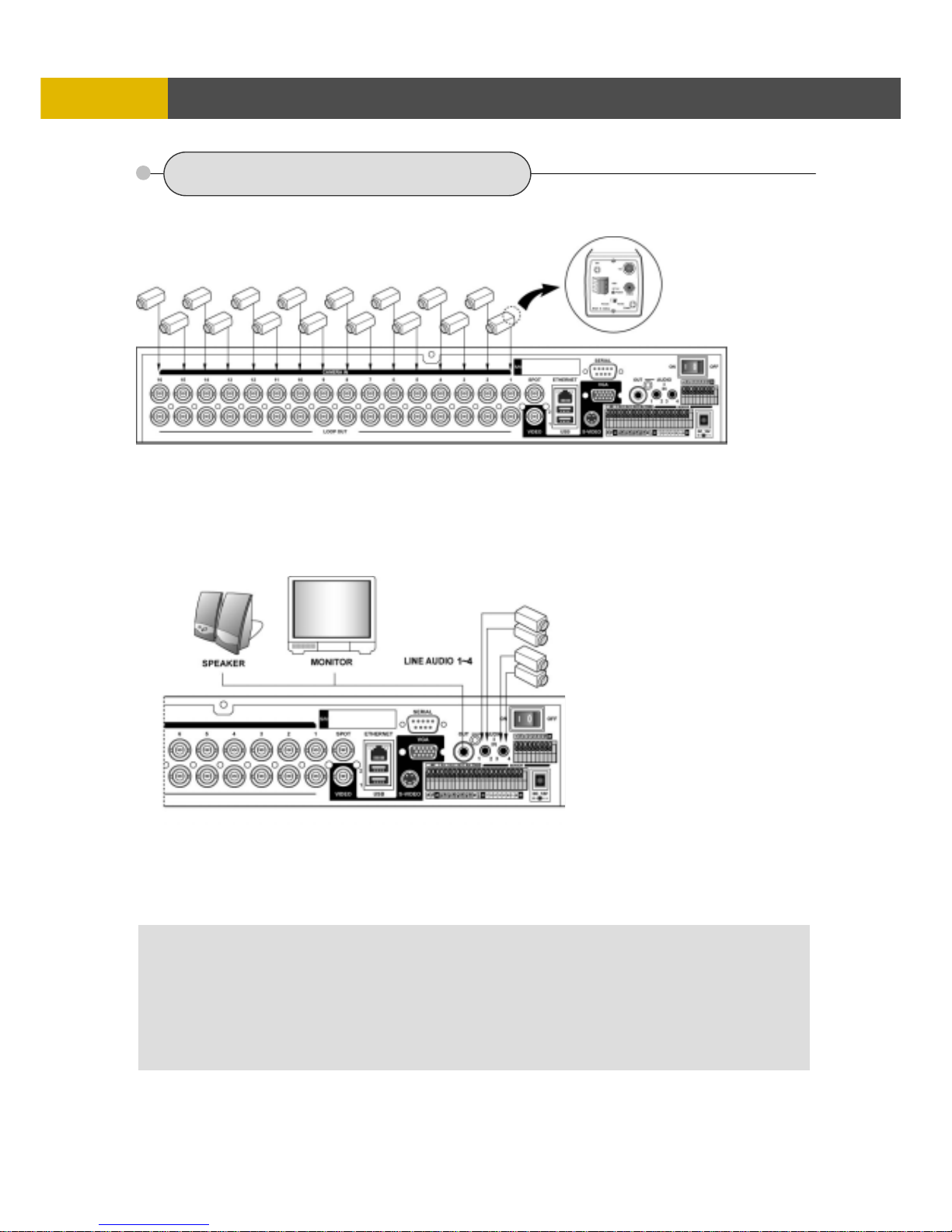
* Connect a female BNC connector of each camera to a male BNC connector, “CAMERA IN” port.
* Connect the looping BNC output to other inputs as required
4.2.2 Audio (*Refer to the specification)
Audio Input
- AUDIO IN : Connect the RCA Line Jack of the relevant equipment (for example, a camera with
a built-in microphone) to the AUDIO IN port
Audio Output
- AUDIO OUT : Connect the RCA Line output to a monitor with a built-in speaker
NOTE
This DVR can be connected only with a line audio and not support a microphone for audio input and output.
To record audio should be enable in the AUDIO setup at the MENU setup.
You can select audio channels regardless of cameras.
** Please refer to 5.2.13 AUDIO SELECT.
Page 13
DIGITAL VIDEO RECORDER
13
INSTALLATION
4.2.3 Monitor
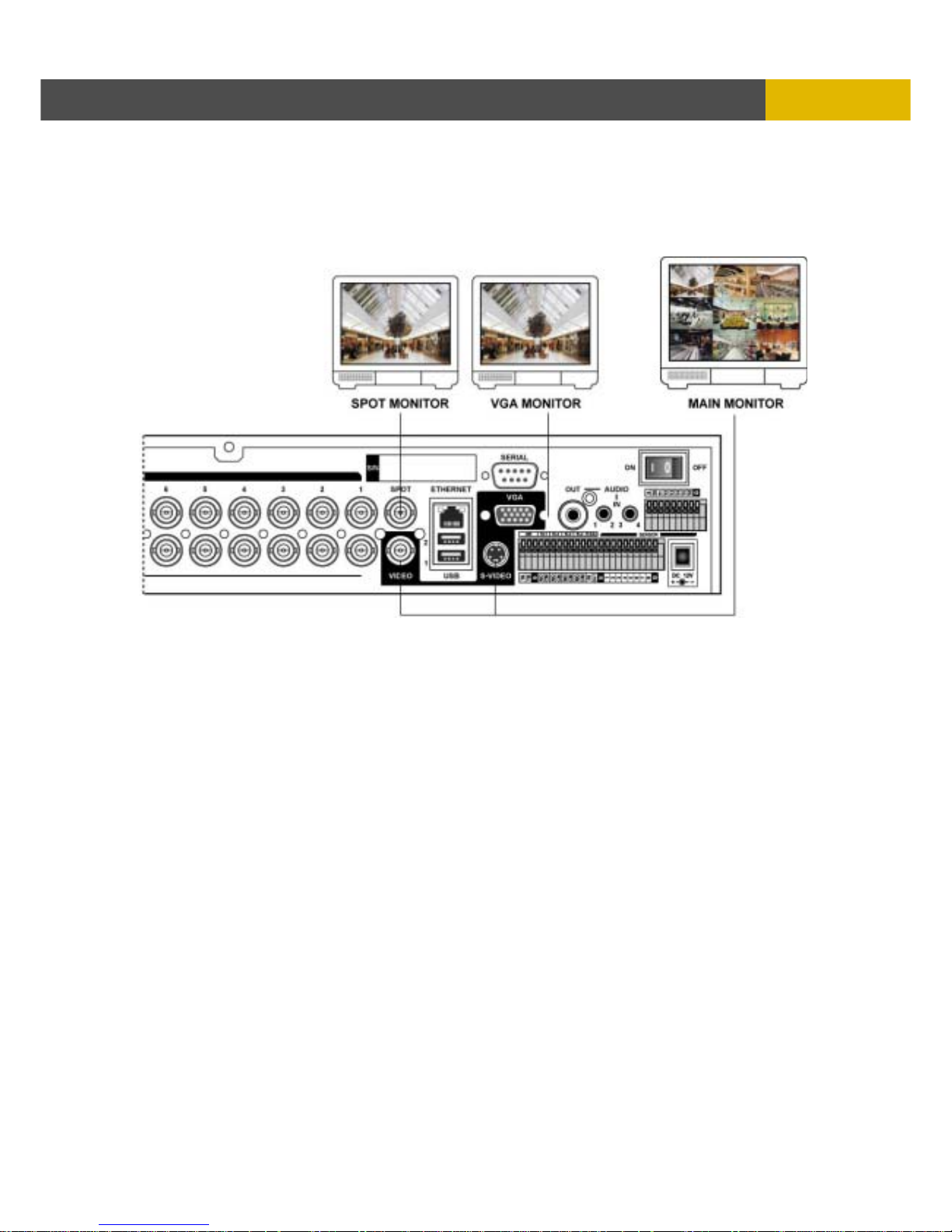
- Connect the female BNC for monitor output.
- Connect the male Y/C cable socket for S-VIDEO monitor output.
Page 14
14
INSTALLATION
4.2.4 External HDD Bay
(USB output)
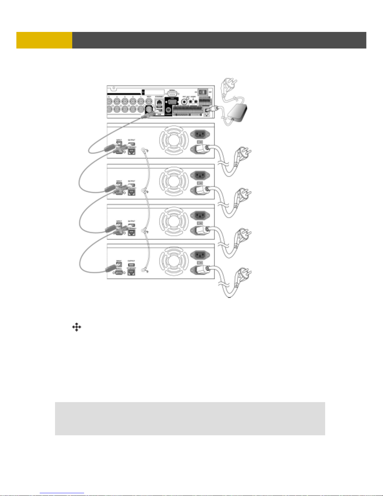
INSTALLATION PROCESS.
1) Turn off the power of DVR.
2) Connect the grounding conductor between DVR and external HDD bay.
3) Connect the USB cable between DVR and external HDD bay.
4) Connect the power cords of DVR and each external HDD bay.
5) Plug the power cords of DVR and each external HDD bay.
6) Turn the power of DVR on.
7) After booting the system automatically, press the STATUS button and check the system
information of setting the HDD. (If the HDD is not recognized properly, turn the power of
DVR off first and check the cable connections referring to user’s manual of external bay.
CAUTION - Do not disjoint the external HDD Bay from DVR in normal operating condition.
NOTE - Please refer to the external ba
y
manual for more information.
Page 15
DIGITAL VIDEO RECORDER
15
INSTALLATIO
N
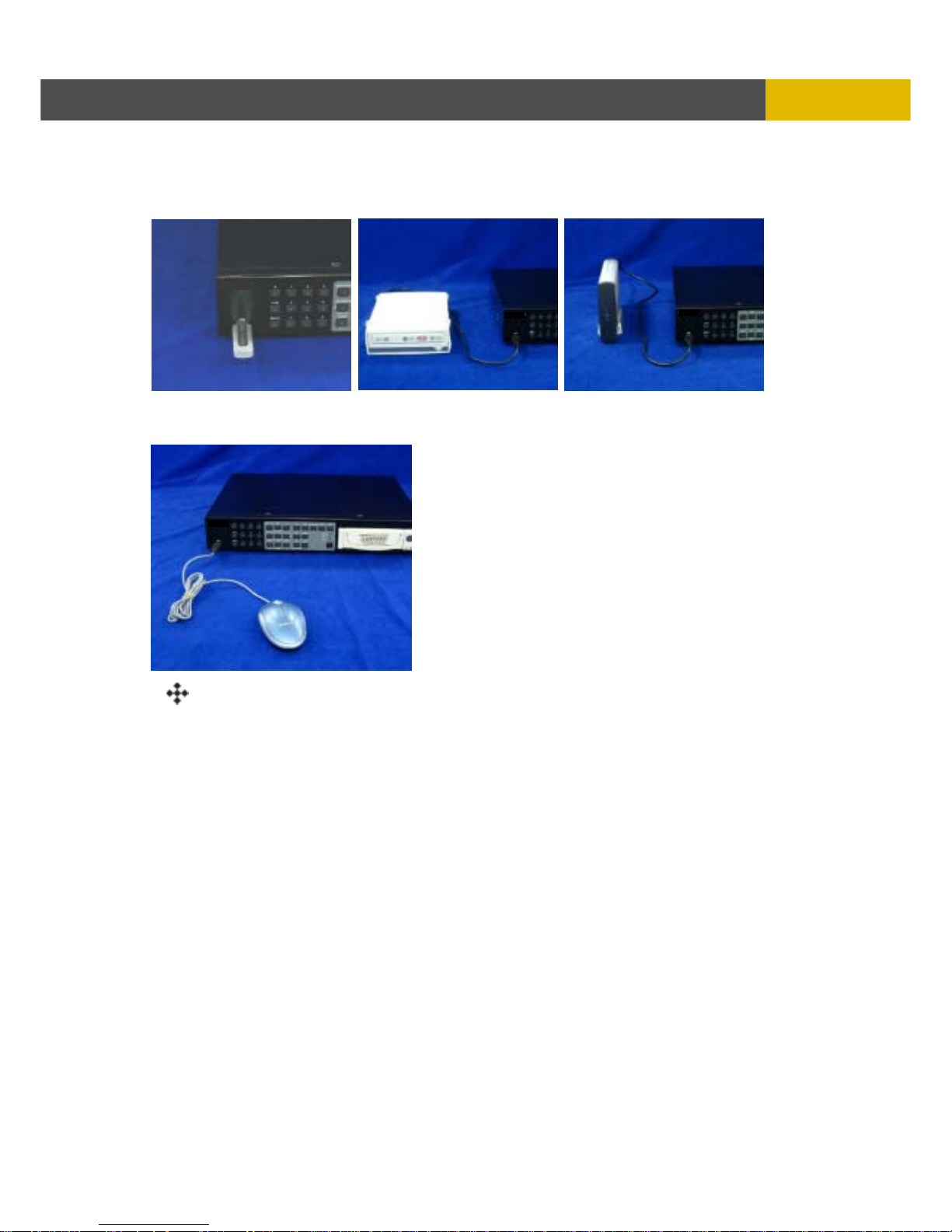
4.2.5 USB 2.0 ports
○
1
Three USB ports are provided to connect a USB memory stick, One USB port is on the front
panel and the other two are on the rear panel.
○
2
A USB mouse can be connected to one of the ports. You can use the mouse to navigate
through the screens and menus much like you would on a computer.
INSTALLATION PROCESS.
Connect the desired device with DVR as the above pictures.
(For example, USB memory stick, mouse, external storage device etc.)
NOTE: You have to turn on the power of USB storage devices after DVR is booted completely.
Page 16

16
OPERATION
Chapter 5 Operation
5.1 FACTORY DEFAULT
* 16CH DVR
MENU Setup>
QUICK SETUP>
QUICK SETUP…………………….….…….…..…...OFF
IMAGE SIZE……………………….………………....720x240
RECORD FRAME……………………….……….…..60
EVENT……….…………………………...…………...ALL
PRE RECORD TIME……….…………...….………..5SEC
POST RECORD TIME………………….…...……....10SEC
IMAGE QUALITY…..…………………………………FINE
AUDIO RECORD…………………………….……….OFF
REMOTE CONTROL ID…………….…..……….…..ALL
SCREEN>
AUTO SEQUENCE
QUAD-A~E/ SIX/ SEVEN/
NINE-A~B/ TEN/ THIRTEEN/ SIXTEEN….3SEC
ADD AUTO SINGLE….………………..…...OFF
AUTO-SINGLE CH1~16………………..…..3SEC
VIDEO LOSS SKIP..…………………….…..ON
DISPLAY
HDD FREE SPACE.……………….………..ON
HDD FREE SPACE MODE..…...…………..PERCENT
RECORD STATUS..………………………...ON
CLOCK DISPLAY…………………..……..…ON
DATE & TIME MODE..…………….……..… YY/MM/DD
TITLE DISPLAY………………………....…..ON
TITLE MODE…………………………..….....TEXT
BORDER COLOR.………………………..…WHITE
REMOTE CONTROL ID..………….……..…OFF
TITLE
CH 1~CH 16………………………….……….CH 1~CH16
MULTI SCREEN
MULTI 4E………………………………….….2/ 4/ 6/ 8
MULTI 6……………………………………….1/ 2/ 3/ 4/ 5/ 6
MULTI 7……………………………………….1/ 2/ 3/ 4/ 5/ 6/ 7
MULTI 9B……………………………………..10/11/12/13/14/15/16/1/2
MULTI 10………………………………………1/ 2/ 3/ 4/ 5/ 6/ 7/ 8/ 9/ 10
MULTI 13………………………………………1/ 2/ 3/ 4/ 5/ 6/ 7/ 8/ 9/ 10/ 11/ 12/ 13
COVERT
CH 1~16………………………….….….……..OFF
SELECT……………………………….……….LV&PB&NW
COVERT TITLE DISPLAY……………………OFF
SPOT
SPOT MODE……………………….………….MANUAL
SPOT SEQUENCE TIME….……………..…..3SEC
VIDEO LOSS SKIP……………………………ON
CAMERA
CHANNEL …………………………………….... 1
Page 17

DIGITAL VIDEO RECORDER
17
OPERATIO
N
BRIGHTNESS ……………………………….…. 50%
CONTRAST………………………………….….. 50%
HUE ……………………………………………… 50%
SATURATION…………………………………... 50%
RECORD>
RECORD SETUP
RECORD PROGRAM..…………………….....6
RECORD PROGRAM (Refer to 6.3.2)
IMAGE QUALITY
RECORD QUALITY………………………........FINE
AUDIO RECORD
AUDIO 1~4………………..…………………......OFF
REPEAT RECORD
REPEAT RECORD……....……………………..ON
REPEAT RECORD ALARM.……………….…..5%
PLAY MODE.…………………………………….….......FRAME
BACKUP MODE..……………………………….…........OFF
HOLIDAY
HOLIDAY RECORD………………………….….OFF
HOLIDAY SETUP(MM/DD) ………………..…..00/00
EVENT>
MOTION DETECTION
CHANNEL…………………………………...…...1
SENSITIVITY…………………………...….…….5
EVENT SCREEN MODE…………………...…….….…SCREEN HOLD
EVENT CHECK.………………………….…..…….……OFF
EVENT MESSAGE..…………………………….……....OFF
EVENT MESSAGE RESET……………….……......….5SEC
EVENT BUZZER..…………………………………..…...OFF
SENSOR INPUT
SENSOR 01~16 INPUT TYPE..………………..NOT USED
RELAY OUTPUT
CH 1~16: ALARM/ V-LOSS/ MOTION..…….…1/ 2/ 3
RELAY 1~3 OUTPUT TIME..……………...……1SEC
RELAY 4 SELECT.….………………….…..……POWER
SYSTEM>
HDD
HDD CONFIGURATION
REMOVABLE/ FIXED-01~02...……..…. NO HDD
REC HDD INITIALIZE.…..…………………..……NO
BACKUP HDD INITIALIZE……………………….NO
CLOCK
DATE & TIME
TIME ADJUST
INTERNET TIME ADJUST...………… OFF
SELECT TIME SERVER …………….. NONE
SELECT TIME ZONE …………….. GMT+09:00
DAYLIGHT SAVING TIME..…….……. OFF
START TIME ……………………… APR/1ST/SUN/02/AM
END TIME …………………………. OCT/4TH/SUN/02/AM
VIDEO STANDARD…………….………………………...AUTO
LANGUAGE……………….………..………………….….ENGLISH
REMOTE CONTROL ID.…………….………..………… ALL
KEY ECHO…..………………….………………..……….ON
Page 18

18
OPERATION
ADVANCED SETUP
PASSWORD CHECK…………………….……….OFF
SET PASSWORD
ADMIN PASSWORD…..…….……….…..11111111
USER1 PASSWORD.…………..…….…..22222222
USER2 PASSWORD.…………..…….…..33333333
USER3 PASSWORD.…………..…….…..44444444
USER4 PASSWORD.…………..…….…..55555555
USER AUTHORITY
AUTHORITY U1U2U3U4
RECOFFOFFOFFOFF
SEARCH&PLAYOFFOFFOFFOFF
COPYOFFOFFOFFOFF
LIVEAUDIOOFFOFFOFFOFF
DVRSETUPOFFOFFOFFOFF
DVRSTATUSOFFOFFOFFOFF
PTZCONTROLOFFOFFOFFOFF
DVR MENU SETUP
MENU INITIALIZE….…………..………...NO
LOAD MENU FROM FILE
SAVE MENU TO FILE
FIRMWARE UPGRADE………………….……….………NO
LINK>
NETWORK
DHCP……..………………………………….………OFF
IP ADDRESS………………………………………..192 168 000 002
SUBNET MASK……………………………………..255 255 255 000
GATEWAY…………………………………………..192 168 000 001
DNS…………………………………………………..000 000 000 000
PORT……………………………………….………..5400
DYNAMIC IP SERVER…………………………….211.174.251.155
BACKUP IP SERVER……………………………...211.174.251.160
NETWORK FRAME..............................................STILL
RS232C
BAUD RATE..………………….…………….……..115200
DATA BIT……..……………………………….…….8
PARITY BIT….……..……………………….………NONE
STOP BIT……..…………………………….……….1
RS485
SYSTEM ID……..…………………………….…….1
BAUD RATE..………………….……………….…..115200
DATA BIT……..………………………………….….8
PARITY BIT….……..………………………….……NONE
STOP BIT……..……………………………….…….1
PTZ
CH 1~16: MODEL/SPEED/ID….…………………..NONE/9600/1
E-MAIL
SEND E-MAIL………………………………... OFF
SMTP SERVER……………………………… NONE
DVR E-MAIL ADDR…………………………. NONE
OPTIONAL
USER ID……………………………….. NONE
PASSWORD…………………………… NONE
E-MAIL ADDR 1~10…………………… NONE
Page 19

DIGITAL VIDEO RECORDER
19
OPERATIO
N
SEARCH>
CALENDAR SEARCH
SEARCH©
HDD ID………………………………………. NORMAL
CHANNEL…………………………………… ALL
TIME SEARCH
HDD ID………………………………………. NORMAL
CHANNEL…………………..………………. ALL
EVENT SEARCH
HDD ID………………………………………. NORMAL
CHANNEL…………………..………………. ALL
EVENT…………………..…………………… ALL
BLOCK SEARCH
HDD ID………………………………………. NORMAL
FILE SEARCH
MEDIA……………………………………….. USB_FRONT
BOOKMARK SEARCH
LOG FILE
COPY>
COPY
MEDIA……………………………………….. USB_FRONT
HDD ID………………………………………. NORMAL
CHANNEL…………………………………… ALL CHANNEL SELECT
COPY STATUS
COPY START/ END/ CUR TIME.………….………2000/00/00 00:00:00
MEDIA FORMAT
FORMAT MEDIA..…………………………. USB_FRONT
MEDIA FORMAT
MEDIA INFORMATION
MEDIA TOTAL ……………………………… 0MB
EXIT>
EXIT …………………………………………………. SAVE ONLY
Page 20
20
OPERATION
5.2 BUTTON CONTROLS
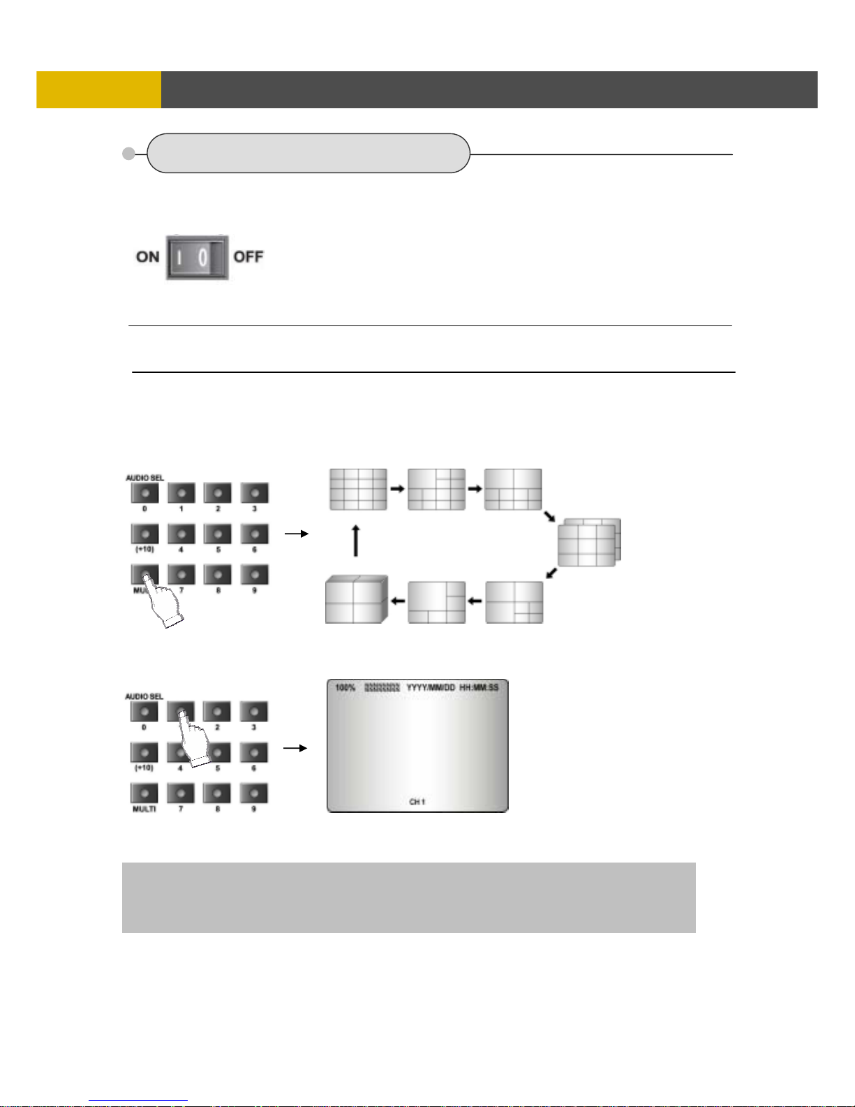
5.2.1 POWER ON /OFF
After the connection of power cord and other devices with this DVR, turn the power on.
a. The video signal system (NTSC or PAL) is set to AUTO.
b. Power Failure Recovery
This DVR automatically reverts back to programmed record
parameters upon power restoration.
5.2.2 SCREEN DISPLAY
5.2.2.1 Multi-Display & Full Screen display
a. Multi display
To change a single camera display to the multi camera, press the MULTI button.
b. Full screen display
Press the desired camera number button to display on the monitor.
• If there is no video signal at the video signal system is “AUTO”, the video signal system is set to NTSC. Do not input the PAL
type video signal or it may cause the DVR’s malfunction. In this case, turn off and on again.
Use the +10 Button when you select two digit camera numbers.
EX) Camera Number 12 = Press the +10 Button, and then press the No. 2 Button.
CAMERA/NUMBER INPUT buttons are used to input the password in the password lock function.
Page 21
DIGITAL VIDEO RECORDER
21
OPERATION
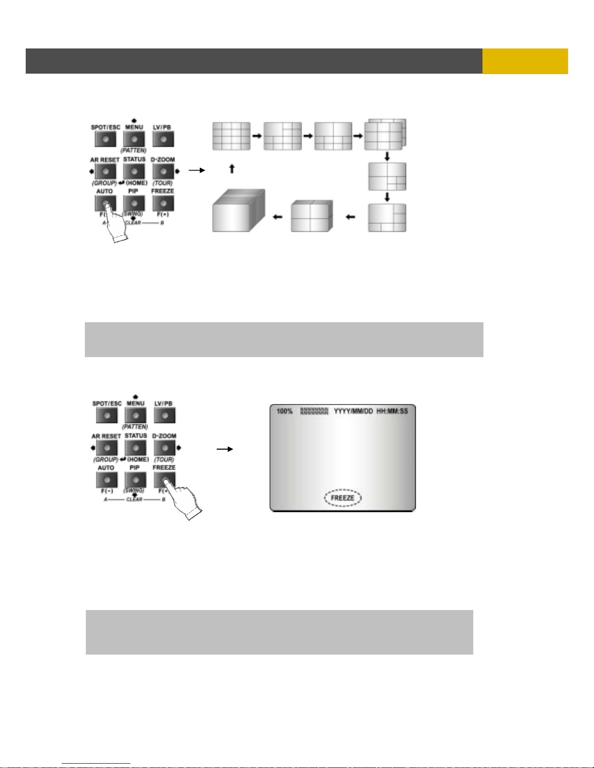
5.2.2.2 Auto Sequence Display
<ADD AUTO SINGLE : ON>
- Press the AUTO button, each screen display will be automatically switching according to the AUTO
SEQUENCE setup.
- If you set up “ADD AUTO SINGLE : OFF” in the AUTO SEQUENCE setup menu, the single display
will be skipped.
- To view the single display, set up “ADD AUTO SINGLE : ON” in the AUTO SEQUENCE setup
menu and the single display will be included in the auto sequence display.
- Press the AUTO button again to exit the AUTO mode.
5.2.2.3 Freeze
MULTI SCREEN MODE
At the Multi display mode, press the FREEZE button and then select the desired camera number.
Press the FREEZE button again to release the FREEZE mode.
SINGLE SCREEN MODE
Press the FREEZE button after the desired channel is selected.
Press the FREEZE button again to release the FREEZE mode.
- If you press the MULTI button after pressing the FREEZE button, all the channels will display
still images.
- FREEZE function is not available, when auto mode is selected.
(Refer to AUTO SEQUENCE in the SCREEN menu for further information)
If an event takes place, the AUTO SEQUENCE mode will be cancelled.
Please refer to the AUTO SEQUENCE of Chapter 6 MENU setup for more information.
Page 22
USER’S MANUAL
22
OPERATION
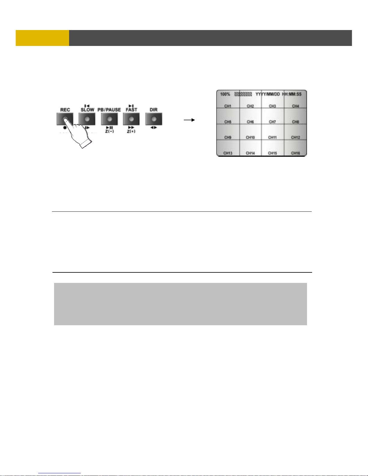
5.2.3 RECORD
Press the REC button and the following message will be displayed as below;
MANUAL MODE
Press the REC button to begin recording.
To stop recording, press the REC button again. The screen will be turned into real time display
mode.
SCHEDULE MODE
When Schedule mode is selected, the recording will be automatically executed according to the
recording schedule. (Please refer to the SCHEDULE SETUP in the RECORD setup.)
The record indication ( NNNNNNNN ) on the screen will be changed according to the type of
recording and refer to the following.
- “ N ” : Manual recording status.
- “ S ” : Schedule recording status.
- “ E ” : Event recording status. (Motion detection/ Video loss/ Sensor)
- “ - ” : Not recording.
- All channels will be displayed by “E” in case of setting by “ALL CHANNELS” in RECORD PROGRAM
even if an event happened just on one channel.
- “E” will be displayed because in case of “ALL CHANNELS” mode, this unit enters the event record mode
when event happened.
- If a channel has an event, all channels will be recorded by event recording frame rate to be set
in RECORD PROGRAM menu.
Page 23
DIGITAL VIDEO RECORDER
23
OPERATIO
N
5.2.4 SEARCH & PLAYBACK
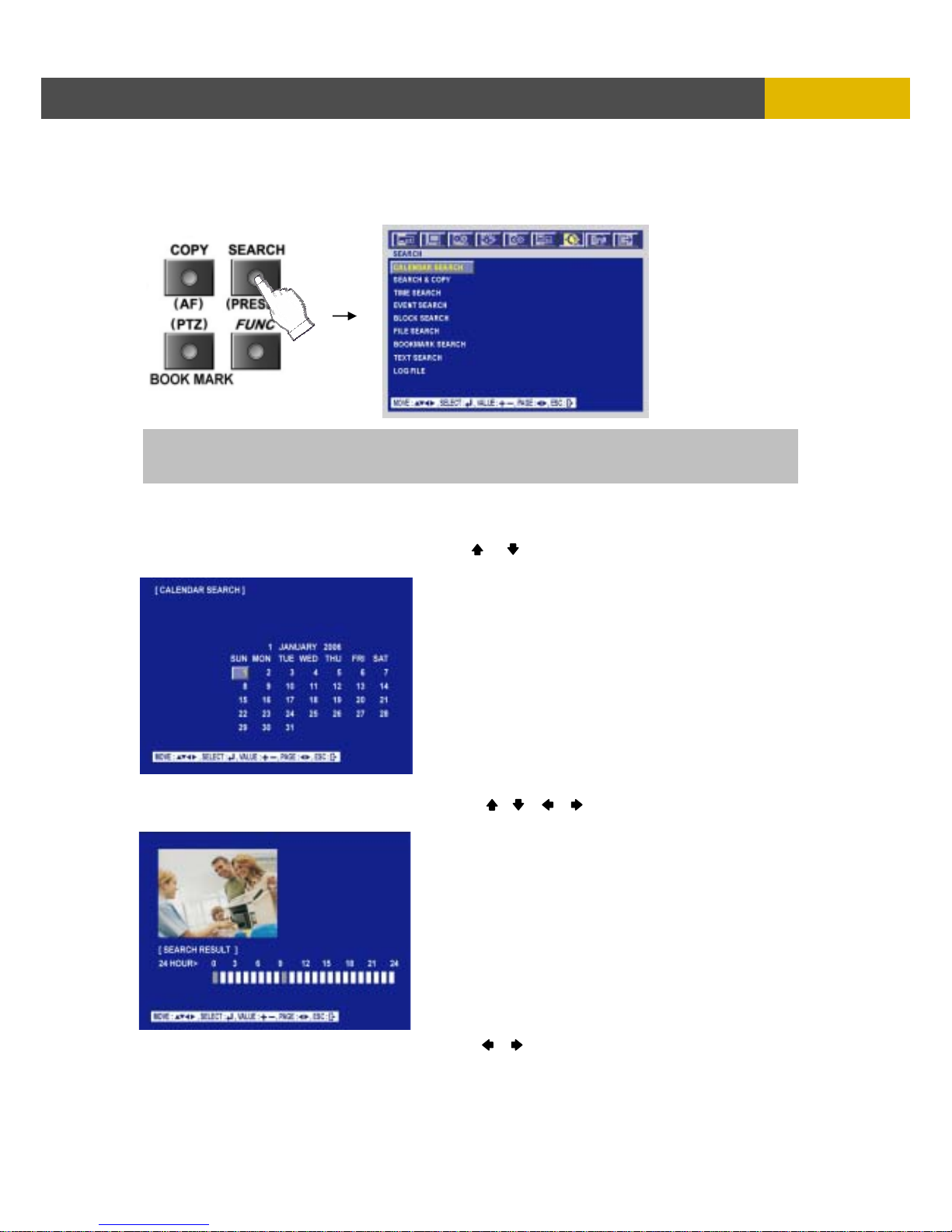
Press the SEARCH button, the SEARCH menu screen appears.
TIME SEARCH
5.2.4.1 CALENDAR SEARCH
At the SEARCH menu;
① Move the cursor to CALENDAR SEARCH using or button.
② Press the ENTER button and the CALENDAR SEARCH screen appears.
* The date is displayed by white in case of no data.
③ Move the cursor to the desired position using the , , , buttons.
④ And then press the ENTER button, and the following screen appears.
⑤ Move the cursor to the desired position using the , buttons and then press the ENTER
button to play the selected time.
If you press the PLAY button in the real time screen mode, playback will be executed from the end of
the previous time search and press the desired channel select button.
To exit the playback mode and see the live screen again, press LV/PB button.
Page 24
USER’S MANUAL
24
OPERATION
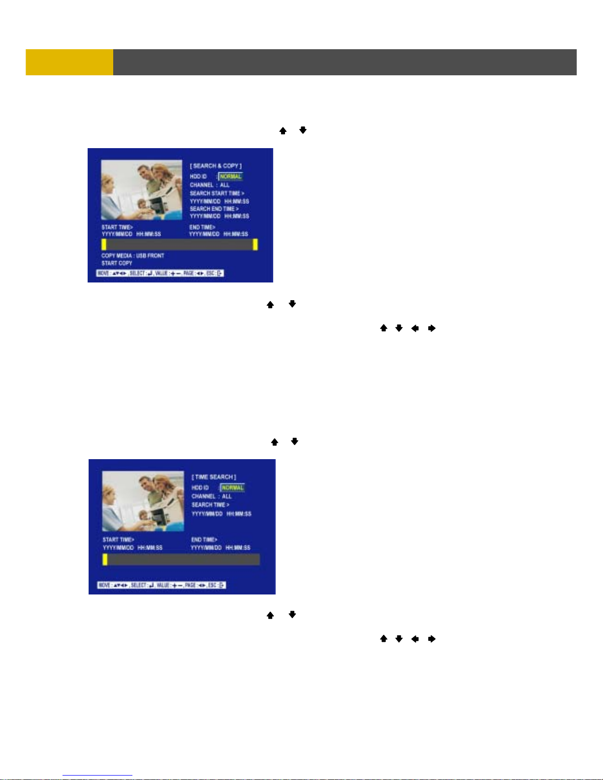
5.2.4.2 SEARCH & COPY
At the SEARCH menu;
① Move the cursor to SEARCH© using or button.
② Press the ENTER button and SEARCH© screen appears.
③ Select the desired HDD ID using the (-) or (+) button.
④ Move the cursor to CHANNEL using the or button and select the desired channel using the
(-) or (+) button.
⑤ Move the cursor to the desired position of SEARCH TIME using the , , , buttons, and
then set up the desired time using the(-), (+) buttons.
⑥ Press the ENTER button and you can playback.
⑦ Press ESC button to go to the previous menu.
⑧ Move the cursor to START COPY and then press the ENTER button to copy.
○
9
Enter a password if you want to protect your file.
If you don’t want a password, press ESC button to start to copy.
5.2.4.3 TIME SEARCH
At the SEARCH menu;
① Move the cursor to TIME SEARCH using or button.
② Press the ENTER button and TIME SEARCH screen appears.
③ Select the desired HDD ID using the (-) or (+) button.
④ Move the cursor to CHANNEL using the or button and select the desired channel using the
(-) or (+) button.
⑤ Move the cursor to the desired position of SEARCH TIME using the , , , buttons, and
then set up the desired time using the(-), (+) buttons to set the search time.
⑥ Press the ENTER button and you can playback.
⑦ Press the LV/PB button to exit this menu.
Page 25
DIGITAL VIDEO RECORDER
25
OPERATIO
N
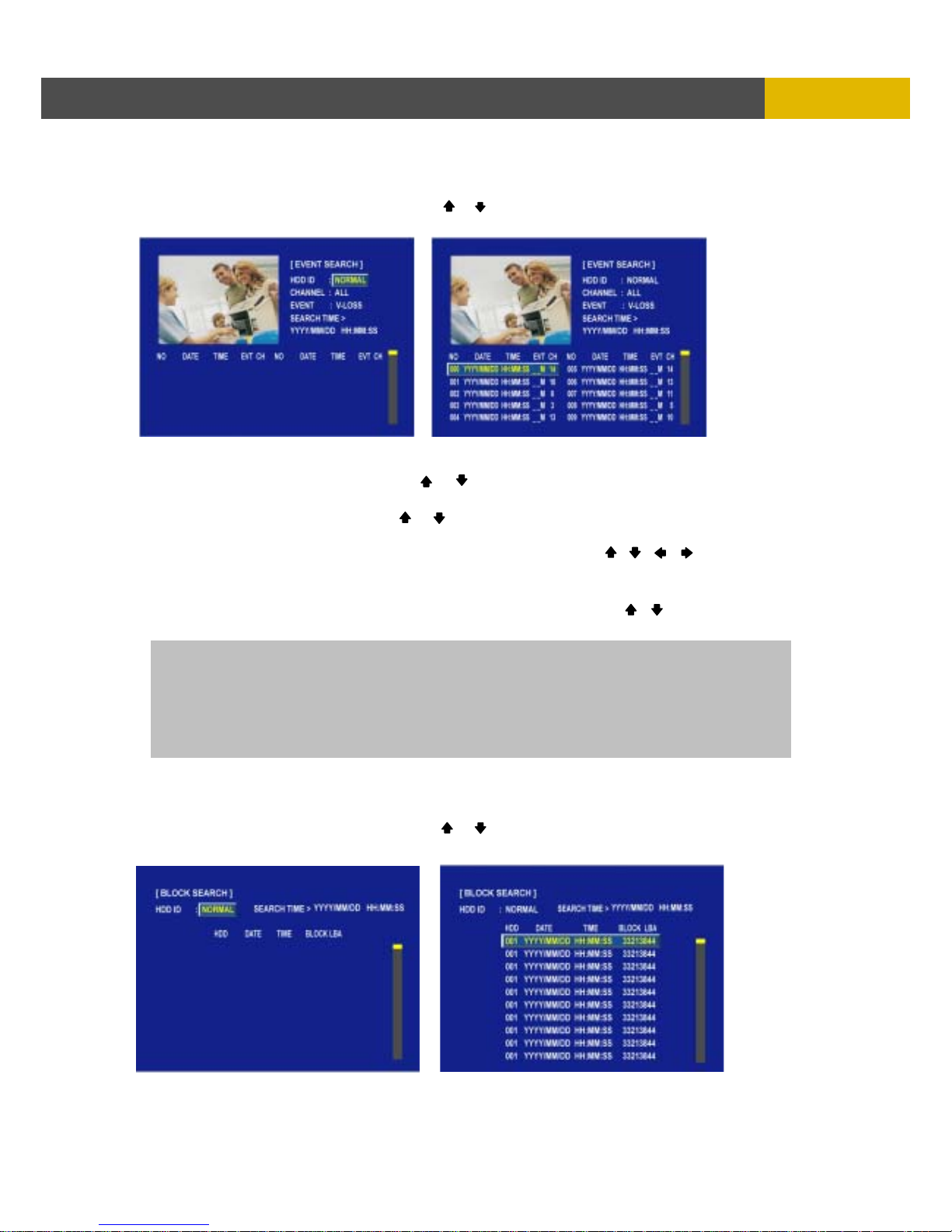
5.2.4.4 EVENT SEARCH
At the SEARCH menu;
① Move the cursor to EVENT SEARCH using or button.
② Press the ENTER button and the EVENT SEARCH menu screen appears.
③ Select the desired HDD ID using the (-) or (+) button.
④ Move the cursor to CHANNEL using the or button and select the desired channel using the
(-) or (+) button.
⑤ Move the cursor to EVENT using the or button and select the event type to search using
the (-) or (+) button.
⑥ Move the cursor to the desired position of SEARCH TIME using the , , , buttons, and
then set up the desired time using the(-), (+) buttons.
⑦ Press the ENTER button, and the event list searched appears.
⑧ When the event list appears on the screen, select the desired list using , buttons and
press the ENTER button for the playback.
5.2.4.5 BLOCK SEARCH
At the SEARCH menu;
① Move the cursor to BLOCK SEARCH using or button.
② Press the ENTER button and the BLOCK SEARCH menu screen appears.
- When video loss is detected, up to five seconds of pre-recording data is stored on the HDD and the
details will be listed in the EVENT LIST. The beep sounds and the LED of the ALARM RESET button will
flicker. Press the ALARM RESET button to remove this signal.
- When the unit receives a signal from the sensor input, DVR begins to record the input data according
to the PRE/POST TIME in the RECORD setup and the details will be listed in the EVENT LIST.
Page 26
USER’S MANUAL
26
OPERATION
③ Select the desired HDD ID using the (-) or (+) button.
④ Move the cursor to the desired position of SEARCH TIME using the , , , buttons, and
then set up the desired time using the(-), (+) buttons.
⑤ Press the ENTER, and the list searched appears.
⑥ When the list appears on the screen, select the desired list using , buttons and press the
ENTER button for the playback.
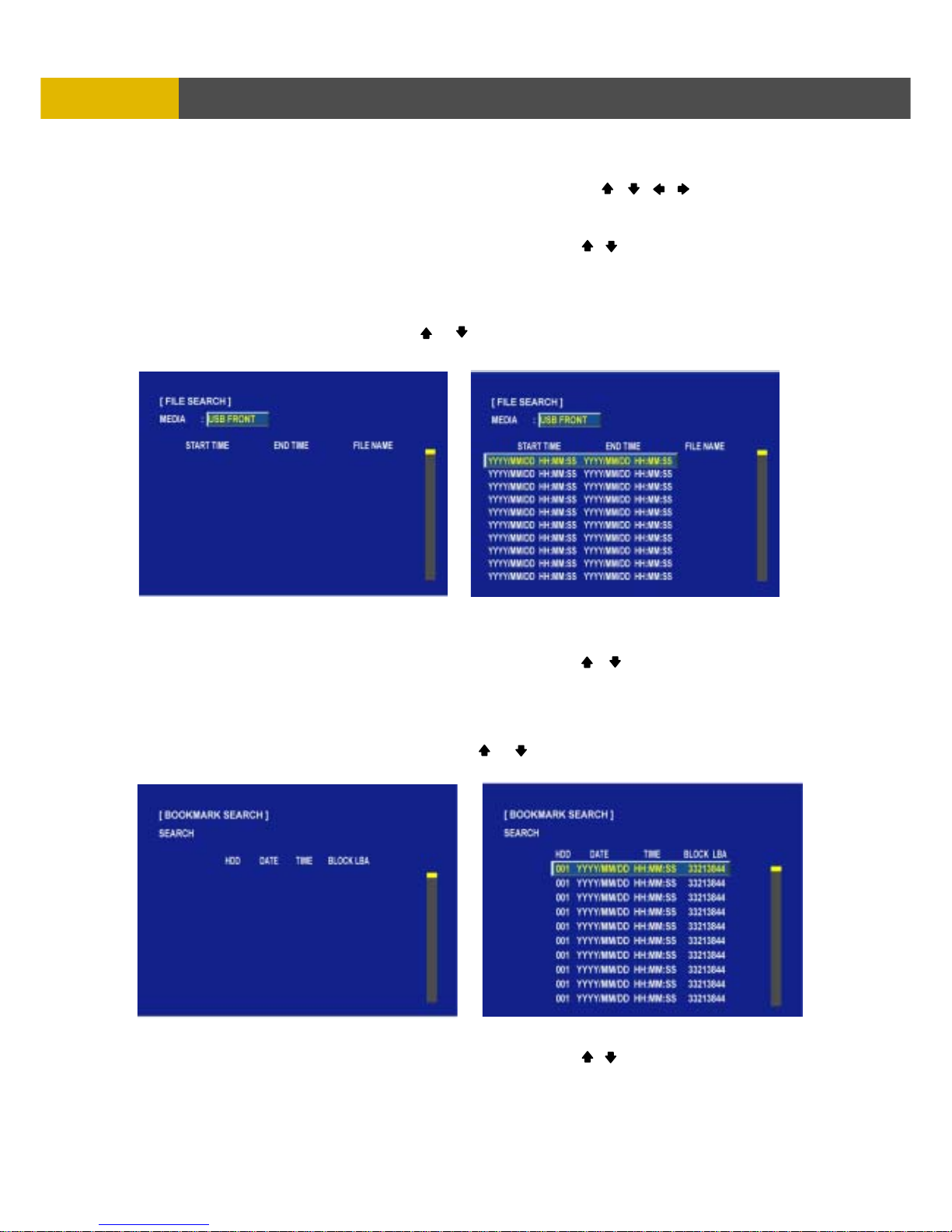
5.2.4.6 FILE SEARCH
At the SEARCH menu;
① Move the cursor to FILE SEARCH using or button.
② Press the ENTER button and the FILE SEARCH screen appears.
③ Select the desired type of MEDIA using the (-) or (+) button.
④ Press the ENTER button, and the list searched appears.
⑤ When the list appears on the screen, select the desired list using , buttons.
⑥ Press the ENTER button for the playback.
5.2.4.7 BOOKMARK SEARCH
At the SEARCH menu;
① Move the cursor to BOOKMARK SEARCH using or button.
② Press the ENTER button and the BOOKMARK SEARCH screen appears.
③ Press the ENTER button, and the list searched appears.
④ When the list appears on the screen, select the desired list using , buttons.
⑤ Press the ENTER button for the playback.
Page 27
DIGITAL VIDEO RECORDER
27
OPERATIO
N
<How to make Bookmark list>
① Press the “PB/PAUSE” button to playback.
② Find the desired image using the SLOW, FAST, DIR buttons.
③ Press the “PB/PAUSE” button to see the still picture of the desired image.
④ Press the “PTZ” button to add the BOOKMARK list.
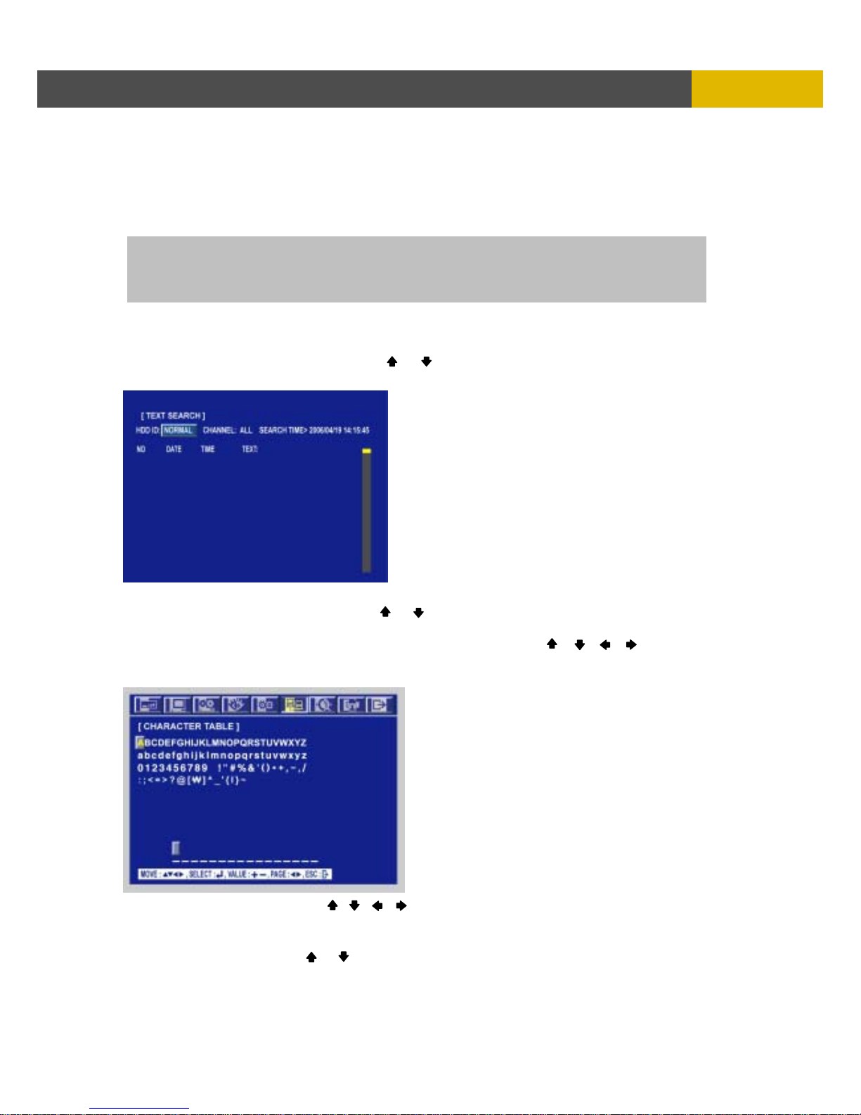
5.2.4.8 TEXT SEARCH
At the SEARCH menu;
① Move the cursor to TEXT SEARCH using or button.
② Press the ENTER button and the TEXT SEARCH screen appears.
③ Select the desired HDD ID using the (-) or (+) button.
④ Move the cursor to CHANNEL using the or button and select the desired channel using the
(-) or (+) button.
⑤ Move the cursor to the desired position of SEARCH TIME using the , , , buttons,
and then set up the desired time using the(-), (+) buttons.
⑥ Move the cursor to TEXT and press the ENTER button and the following screen appears.
○
7
Select the character using the , , , buttons and then press the ENTER button.
○
8
To exit this CHARACTER TABLE screen, press the ESC button.
○
9
Press the ENTER button and the list searched appears.
○
10
Select the desired list using or button and then press the ENTER button to play.
CAUTION
ⓐ If the internal HDD(s) is initialized, all of the event images will be deleted.
ⓑ When the unit is in normal recording status, the pre-recording will not be executed.
Character 입력 메뉴
그림 추가
Page 28
USER’S MANUAL
28
OPERATION
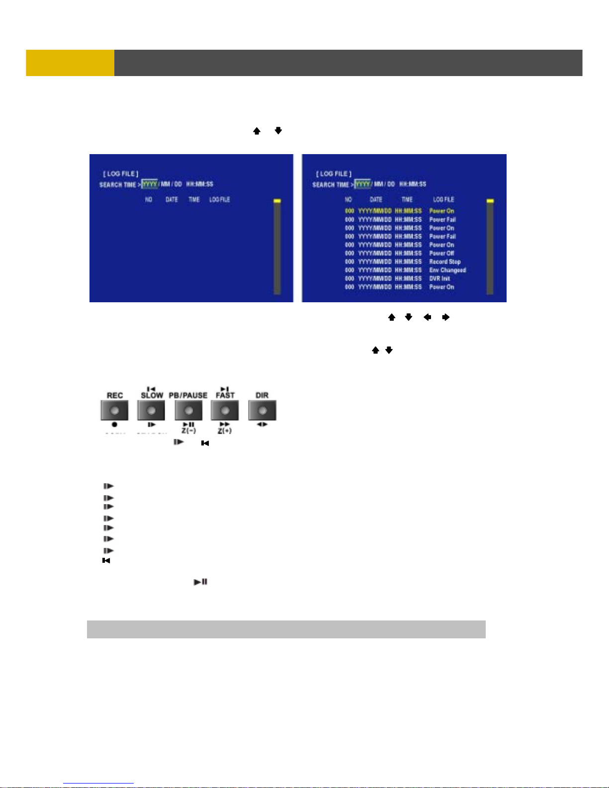
5.2.4.9 LOG FILE
At the SEARCH menu;
① Move the cursor to LOG FILE using or button.
② Press the ENTER button and the LOG FILE screen appears.
③ Move the cursor to the desired position of SEARCH TIME using the , , , buttons,
and then set up the desired time using the(-), (+) buttons.
④ Press the ENTER button, and the list searched appears.
⑤ When the list appears on the screen, select the desired list using , buttons.
5.2.5 PLAY BUTTON INFORMATION
5.2.5.1 SLOW ( )
Press this button to make the speed level which is slower than normal speed (X1) and displayed it at
the upper left side of screen as below;(If you press this button again, the playback speed will be
changed in the order of the below seven speed level)
i. 1/2 - 2 times slower than normal playback speed
ii. 1/4 - 4 times slower than normal playback speed
iii. 1/8 - 8 times slower than normal playback speed
iv. 1/16 - 16 times slower than normal playback speed
v. 1/32 - 32 times slower than normal playback speed
vi. 1/64 - 64 times slower than normal playback speed
vii. 1/128 - 128 times slower than normal playback speed
** : Backward playback still images after pausing of playback image.
5.2.5.2 PB / PAUSE ( ) ( Z- )
Press this button to begin playback at normal speed (X1).
Press this button again to pause the playback.
** ( Z- ) : Zoom out of live view in PTZ mode.
NOTE If you press the “PB” button to playback, it will playback from the end of played final image.
Page 29
DIGITAL VIDEO RECORDER
29
OPERATIO
N
<How to playback a section repeatedly>
① Press the “AUTO” button to set up the A position(starting position) and “(A- )” will be displayed on
upper right of the screen.
② And then press the “FREEZE” button to set up the B position(ending position) and “(A-B)” will be
displayed on upper right of the screen and played between A to B repeatedly.
<How to release the section repetition playback>
Press the “PIP(CLEAR)” button and section repetition playback will cancel.
5.2.5.3 FAST ( ) ( Z+ )
Press this button to make faster the speed level which is higher than normal speed (X1) and
displayed at the upper left side of screen as below:
i. 2 - 2 times faster than normal playback speed
ii. 4 - 4 times faster than normal playback speed
iii. 8 - 8 times faster than normal playback speed
iv. 16 - 16 times faster than normal playback speed
v. 32 - 32 times faster than normal playback speed
vi. 64 - 64 times faster than normal playback speed
vii. 128 - 128 times faster than normal playback speed
(However much data may be recorded can be searched in 3 seconds)
** : Forward playback still images after pausing of playback image.
** ( Z+ ) : Zoom in of live view in PTZ mode.
5.2.5.4 DIRECTION ( )
Press this button to change direction to forward ( )or backward ( ) in playback mode.
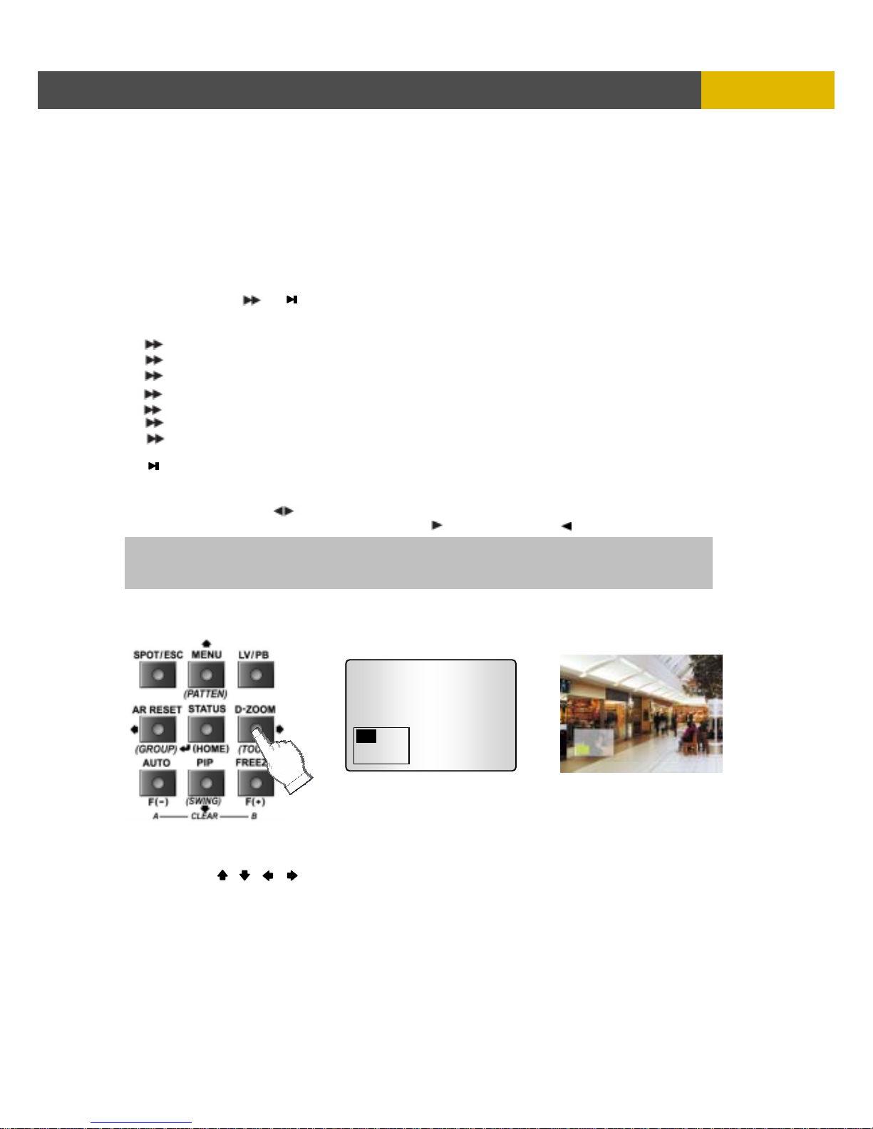
5.2.6 DIGITAL ZOOM
① Press the desired camera number button you wish to display on the monitor.
② Press the D-ZOOM button. The indication screen appears on the main screen.
③ Press the , , , buttons to select the desired location.
④ Press the ESC button to exit this screen.
NOTE
Press DIR button to make a reversed playback from the end of recorded or played images
during the real time display mode.
Page 30
USER’S MANUAL
30
OPERATION
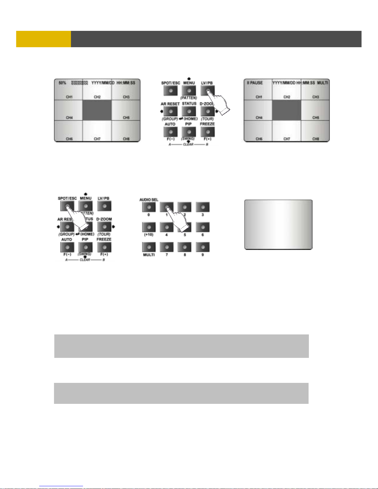
5.2.7 SCREEN SELECT(LV/PB)
During the playback, press the LV/PB button to convert the screen into real time display mode.
(Press this button again to return to the playback mode.)
5.2.8 SPOT MONITOR
Set up the desired mode in “SPOT” of “SCREEN MENU” before executing the SPOT mode.
5.2.8.1 MANUAL MODE
① Press the “SPOT” button on the front panel to toggle “SPOT” mode indicated on the main monitor.
② Press a camera button to display that camera on the spot monitor.
③ OSD of the selected channel will be indicated at the upper left of screen in live mode.
5.2.8.2 EVENT MODE
The Spot monitor will display the channel which an event happened if you select this mode and an
event happens.
5.2.8.3 SEQUENCE MODE
Full screen and split screens will be displayed on the Spot monitor in sequence.
** Please refer to 6.2.6 SPOT of SCREEN.
NOTE
If you press the “SPOT” button after setting this mode, you can control the spot monitor manually.
NOTE
If you press the “SPOT” button after setting this mode, you can control the spot monitor manually.
Spot Monitor
Page 31
DIGITAL VIDEO RECORDER
31
OPERATIO
N
5.2.9 COPY
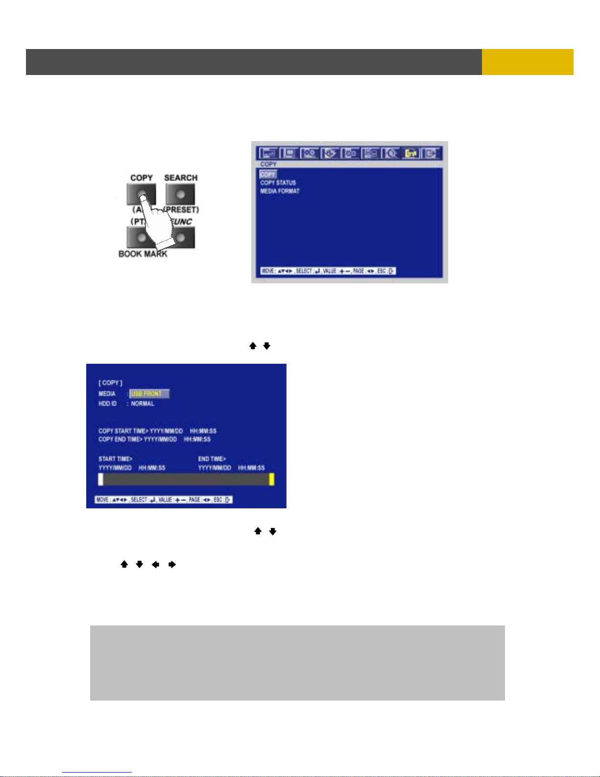
Press the COPY button to copy the recorded images into other media and the COPY MENU screen
appears.
5.2.9.1 COPY
5.2.9.1-1 COPY TO EXTERNAL HDD
At the COPY menu,
① Move the cursor to COPY using the , buttons.
② Press the ENTER button and the following screen appears.
③ Select the desired MEDIA using (-), (+) buttons.
④ Move the cursor to HDD ID using the , buttons and select the desired HDD to copy among
HDD IDs using the (-), (+) buttons.
⑤ Move the cursor to the desired position of COPY START TIME/ COPY END TIME using
the , , , buttons and press the (-) or (+) button to set up the time to set up the COPY
START TIME and COPY END TIME.
** Scroll bar - It can operate with just Mouse click.
⑥ Press the ENTER button to copy.
** You can see a password input message. You need this password when opening the file in
network viewer.
NOTE
When the copy is in process, the copying status (ex. “COPY 30%” ) will be displayed on the right side of
the monitor.
You can search and playback the copied images in HDD with DVR itself
(Please refer to 5.2.4.6 FILE SEARCH.)
** You have to format in case of the media to be used in DVR for the first time.
Page 32
USER’S MANUAL
32
OPERATION
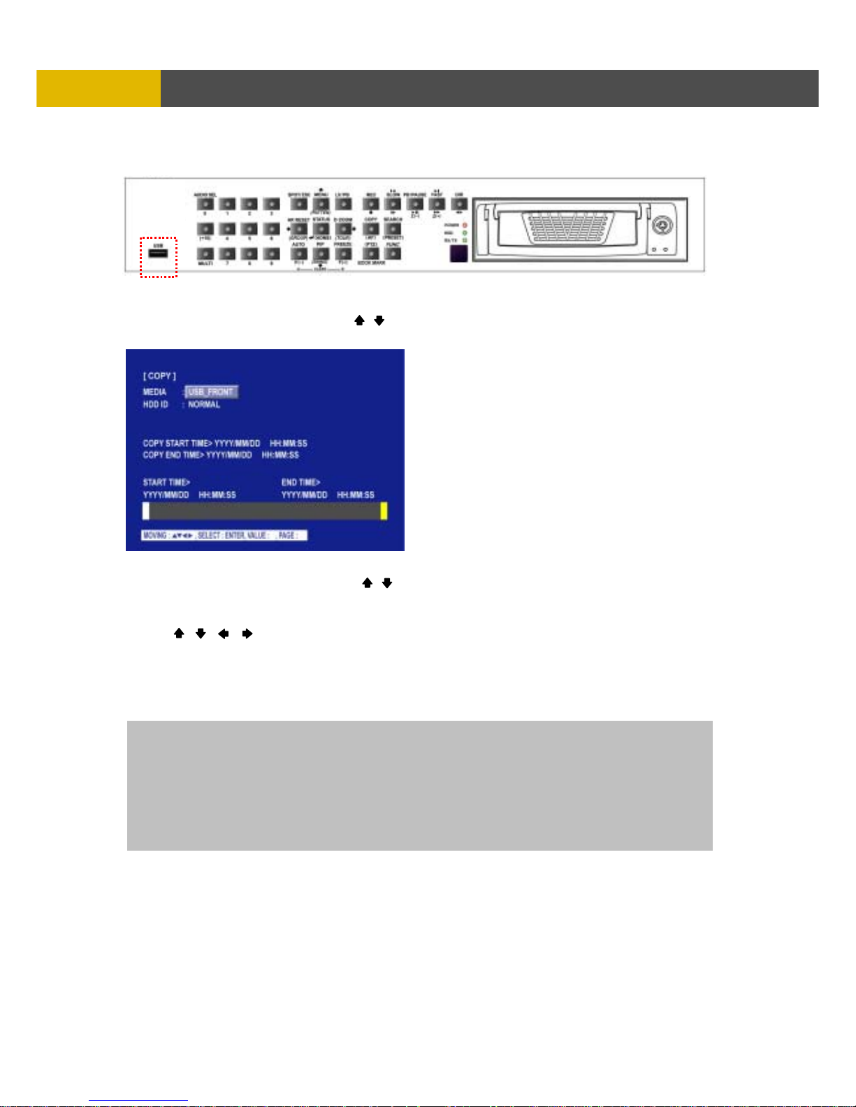
5.2.9.1-2 COPY TO USB memory stick
At the COPY menu,
① Move the cursor to COPY using the , buttons.
② Press the ENTER button and the following screen appears.
③ Select the desired MEDIA using (-), (+) buttons.
④ Move the cursor to HDD ID using the , buttons and select the desired HDD to copy among
HDD IDs using the (-), (+) buttons.
⑤ Move the cursor to the desired position of COPY START TIME/ COPY END TIME using
the , , , buttons and press the (-) or (+) button to set up the time to set up the COPY
START TIME and COPY END TIME.
** Scroll bar: - It can operate with just Mouse click.
⑥ Press the ENTER button to copy.
** You can see a password input message. You need this password when opening the file in
network viewer.
When the copy is in process, the copying status(ex. “COPY 30%”) will be displayed on the right side
of the monitor.
You can search and playback the copied images in USB stick memory with DVR itself as well as PC.
(Please refer to 5.2.4.6 FILE SEARCH.)
** You have to format in case of the media to be used in DVR for the first time.
Page 33
DIGITAL VIDEO RECORDER
33
OPERATIO
N
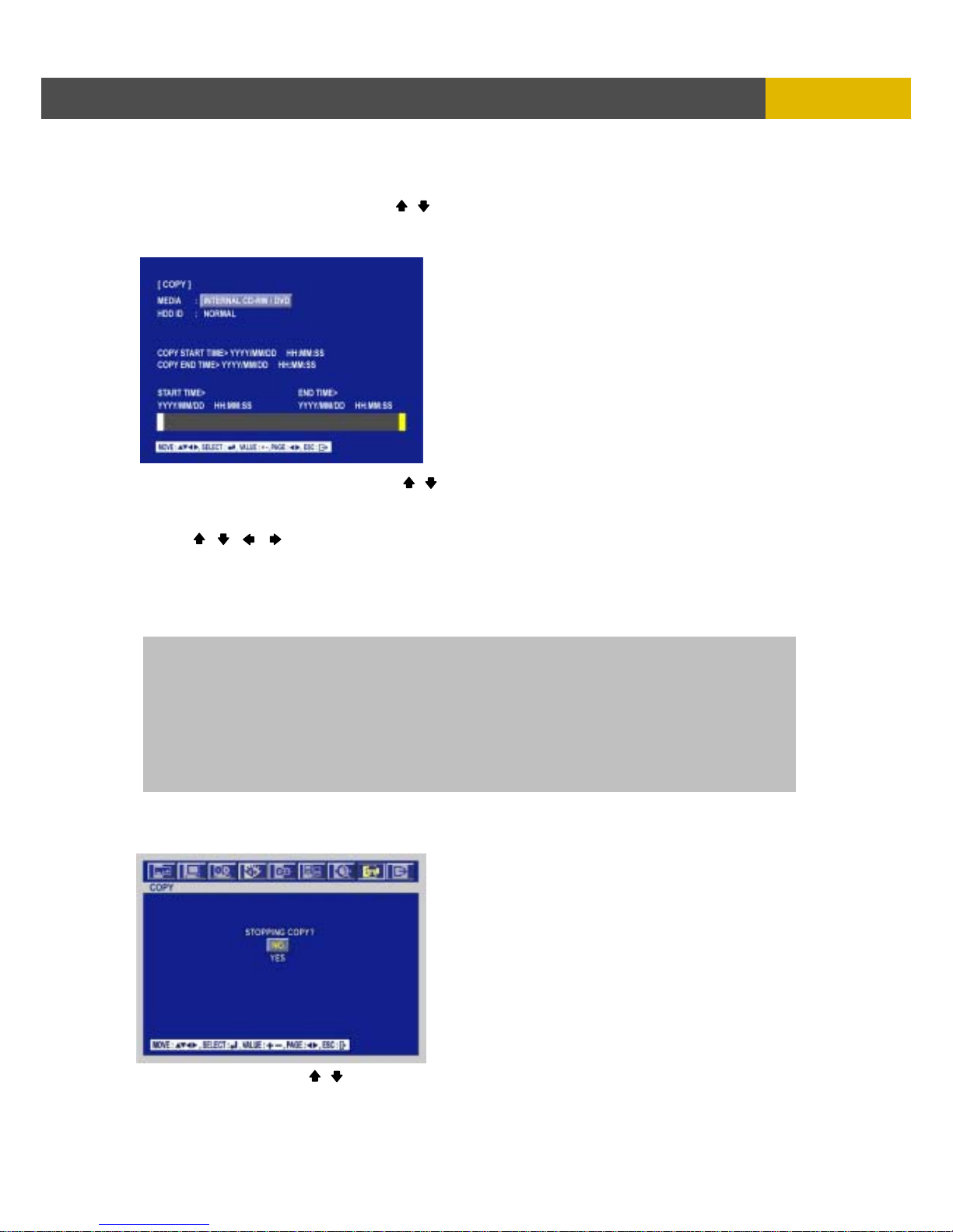
5.2.9.1-3 COPY TO CD-R/ CD-RW/ DVD±RW/ DVD-RAM
At the COPY menu,
① Move the cursor to COPY using the , buttons.
② Press the ENTER button and the following screen appears.
③ Select the desired MEDIA(INTERNAL CD-RW/DVD) (-), (+) buttons.
④ Move the cursor to HDD ID using the , buttons and select the desired HDD to copy among
HDD IDs using the (-), (+) buttons.
⑤ Move the cursor to the desired position of COPY START TIME/ COPY END TIME using
the , , , buttons and press the (-) or (+) button to set up the time to set up the COPY
START TIME and COPY END TIME.
** Scroll bar: - It can operate with just Mouse click.
⑥ Press the ENTER button to copy.
** You can see a password input message. You need this password when opening the file in
network viewer.
5.2.9.1-4 STOPPING COPY
Press the COPY button to stop copying and the following screen appears.
Move the cursor using the , buttons and select “YES” or “NO” and then press the ENTER
button.
NOTE
- CD-R, CD-RW or DVD±RW/RAM is option and this DVR need the interface board to install
a built-in CDR, CD-RW or DVD±RW/RAM.
** You can’t use DVD±R media.
- If you want a external CD-RW or DVD±RW, must purchase it from a authorized dealer.
- You can search and playback the copied images in CD or DVD with DVR itself as well as PC.
- The ‘FileViewer’ for the playback of the copied stream is copied to the media also.
(Please refer to 5.2.4.6 FILE SEARCH.)
** You have to format in case of the media to be used in DVR for the first time except CD-R.
Page 34
USER’S MANUAL
34
OPERATION
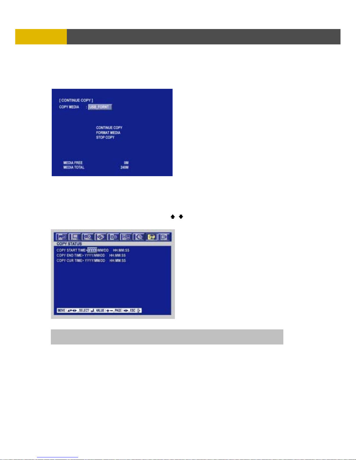
5.2.9.1-5 CONTINUE COPY
① If the media is full or fail during copying, you can see the following message, “MEDIA FULL OR
FAIL PRESS [COPY]” message.
② Press the COPY button and the following screen appears.
③ Move the cursor to the CONTINUE COPY and then press the ENTER button.
5.2.9.2 COPY STATUS
At the COPY menu,
① Move the cursor to COPY STATUS using the , buttons.
② Press the ENTER button to see the current copying status and the following screen appears.
③ Press the ESC button to exit this menu.
CUR TIME : Indicate current copying situation among the total copying data.
Page 35
DIGITAL VIDEO RECORDER
35
OPERATIO
N
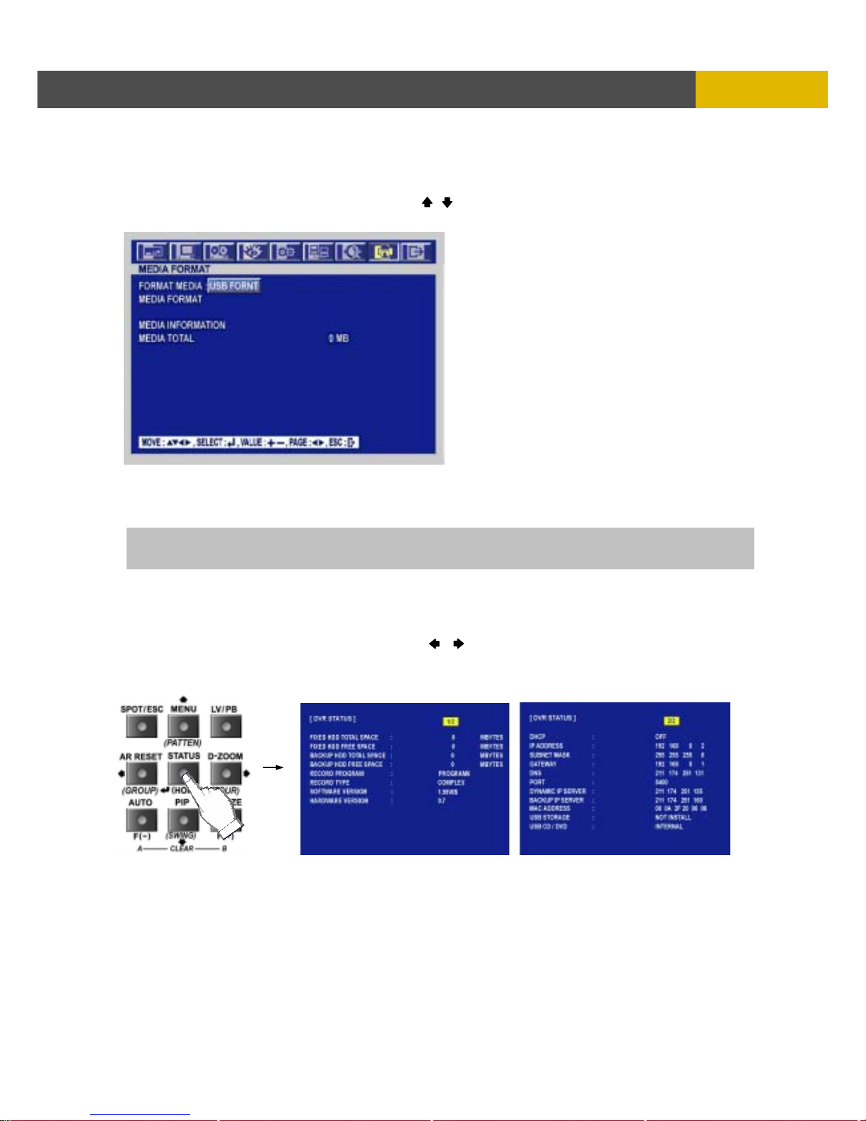
5.2.9.3 MEDIA FORMAT
At the COPY menu,
① Move the cursor to MEDIA FORMAT using the , buttons.
② Press the ENTER button and the following screen appears.
③ Select formatting media using the (-), (+) button.
④ Move the cursor to MEDIA FORMAT and then press the “ENTER” button.
⑤ The message, “FORMATTING” will be displayed while formatting.
5.2.10 DVR STATUS
Press the “STATUS” button or double-click the left button of Mouse, The SYSTEM INFOMATION
screen will appear. To see the next page, press the , or use the wheel scroll of Mouse.
Press the STATUS button again to move on next information screen or press the “ESC” button
to exit the menu.
NOTE
If you don’t connect any media, you can see the message, “Fail”.
Page 36
USER’S MANUAL
36
OPERATION
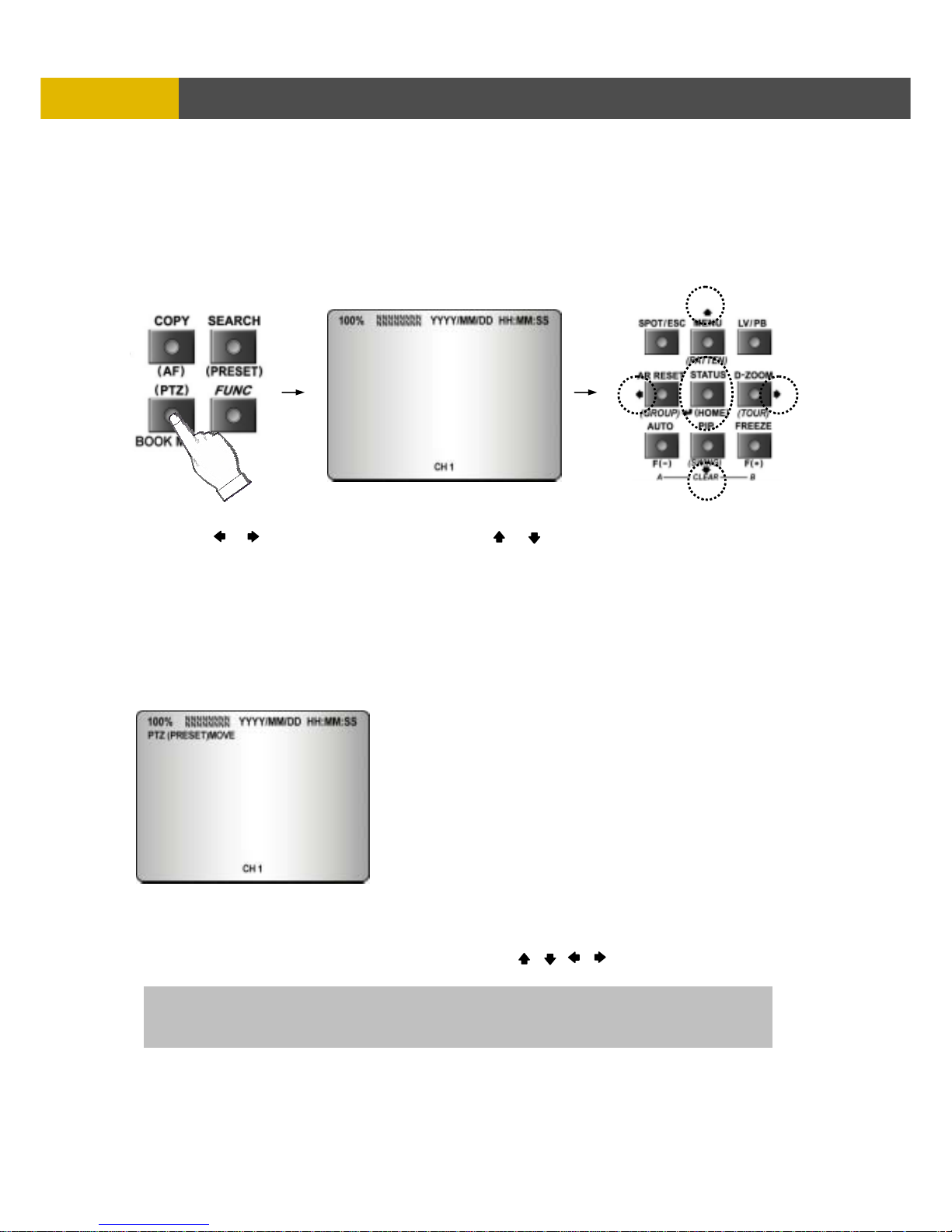
5.2.11 PTZ CONTROL
5.2.11.1 PTZ control in live view
① Press the “PTZ” button to control pan, tilt and zoom functions of PTZ camera and the PTZ
channel, model name and ID will be displayed on the left side of the monitor as the following
picture.
② Press the desired camera button to be displayed.
③ Use the or button to pan left and right and the or button to tilt up and down.
④ Press the PLAY, FAST button to zoom in and out.
⑤ Use the (-) or (+) button to focus. Or press the (AF) button for auto focusing.
⑥ Press the PTZ button again to exit the PTZ mode.
** Please refer to 6.6.4 PTZ setup of SCREEN menu.
5.2.11.2 PTZ PRESETTING
① Press the “PTZ” button to enter PTZ mode.
② Press the “PRESET” button to enter PRESET mode and “PTZ(PRESET)MOVE”, OSD will be
displayed on the left side of the monitor.
③ Move to the desired preset location using the “NUMBER” buttons.
④ Press the “PRESET” button again and “PTZ(PRESET)SET”, OSD will be displayed on the left
side of the monitor.
⑤ Make the desired setting of the PTZ camera using the , , , , (-), (+) buttons.
⑥ Press the “NUMBER” button to set up the revised presetting.
PRESETS
- A preset is a user-defined camera position using pan and tilt, zoom, and focus commands.
This DVR has the Programming capacity for 16 preset locations.
Page 37
DIGITAL VIDEO RECORDER
37
OPERATIO
N
5.2.12 FUNCTION BUTTON
You need this button to control “USER” mode of RELAY 4 SELECT.
Please refer to 6.4.8 RELAY OUTPUT.
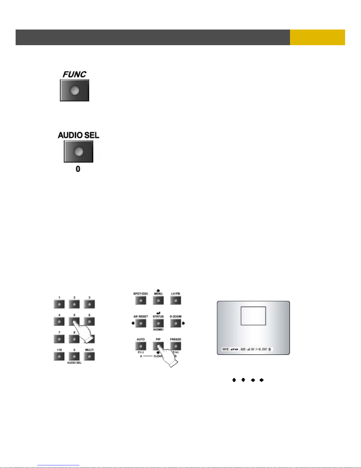
5.2.13 AUDIO SELECT
< Audio select >
You can select audio channels regardless of monitoring screen.
Press the “0(audio select)” button and then press the desired number button and you can hear audio
of selected channel regardless of monitoring screen.
< Link of audio and camera >
Press the “0(audio select)” button and then press the “MULTI” button and you can hear audio of
selected camera.
That is to say, you can hear CH 1 audio when viewing CH 1,
CH 2 audio when viewing CH 2,
CH 3 audio when viewing CH 3 and
CH 4 audio when viewing CH 4.
5.2.14 PIP CONTROL
① Select a single camera in live view, and then press the PIP button and the following screen will
be displayed.
② Select the desired camera that will be displayed on the PIP screen.
③ Press the ENTER button to make the bigger PIP screen and use the , , , buttons to
move the position of PIP screen.
④ Press the ENTER button to change the PIP Box size x2.
⑤ Press the ESC button to exit this mode.
Page 38
USER’S MANUAL
38
OPERATION
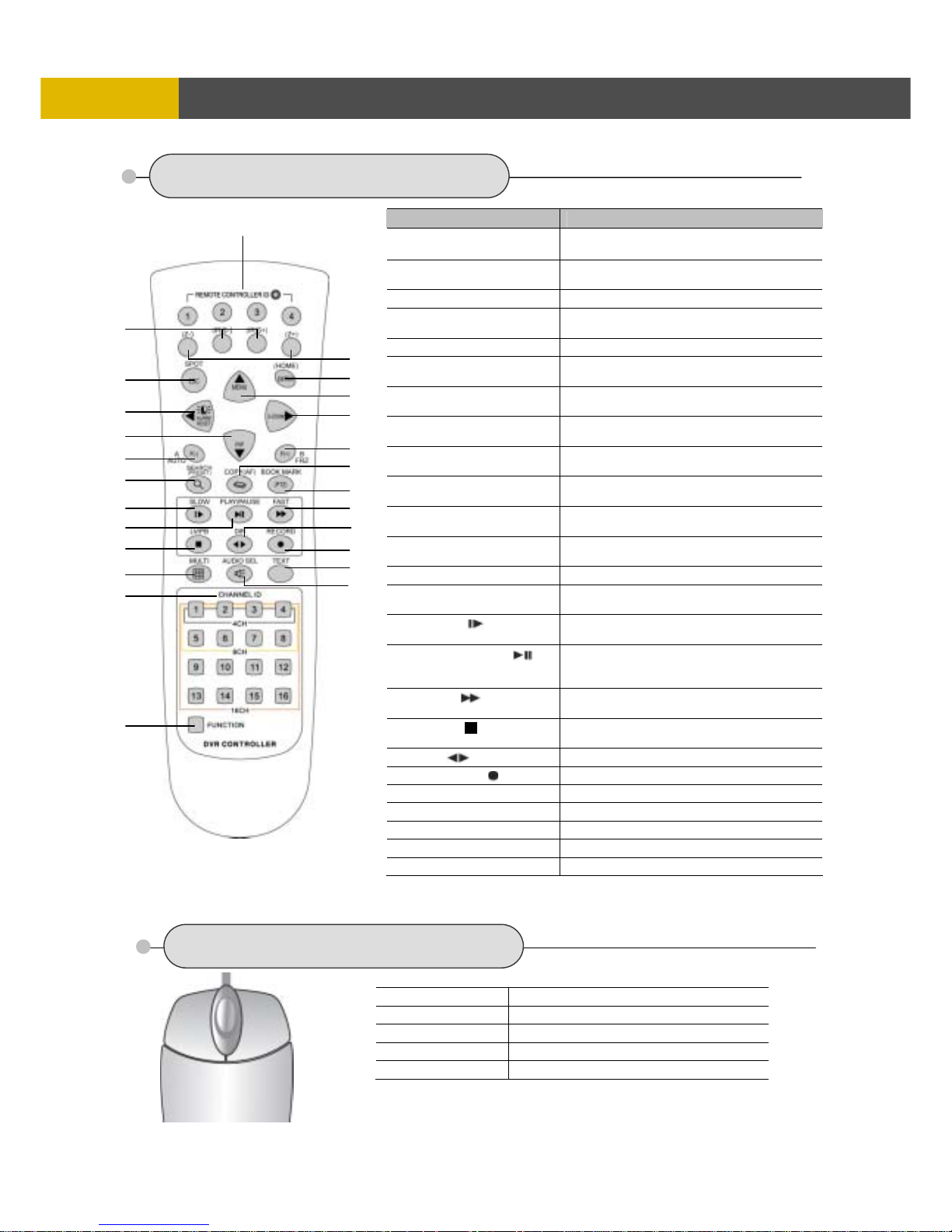
5.3 REMOTE CONTROLLER
5.4 MOUSE CONTROL
Button Name Description
○
1
REMOTE
CONTROLLER ID
Refer to 6.5.6 REMOTE CONTROLLER
ID in the system setup
○
2
(IRIS-/+)
Iris close and open of PTZ /
Frame by Frame(field by field) playback
○
3
(ZOOM-/+) Zoom in and out of PTZ
○
4
SPOT / ESC
Enter the spot mode / Return to the
previous mode
○
5
ENTER (HOME) Enter / Go home in PTZ mode
○6 ( ◀ ) / ALARM RESET
Move the cursor in left direction in the
setup menu. / Release the event signal
○7 ( ▲ ) / MENU
Move the cursor up to the next line in the
setup menu / Display the setup menu
○8 ( ▼ ) / PIP
Move the cursor down to the next line /
Enter the PIP mode
○9 ( ▶ ) / D-ZOOM
Move the cursor in right direction in the
setup menu. / Control of zoom in and out
○
10
AUTO / ( - ) / F(-)
Auto sequence / Downward value /
Focus control of PTZ
○
11
FREEZE / ( + ) / F(+)
Freeze / Up-going value /
Focus control of PTZ
○
12
SEARCH / (PRESET)
Display the search menu /
Enter the preset mode of PTZ
○
13
COPY / (AF) Display the copy menu / Auto focus of PTZ
○
14
BOOKMARK / (PTZ)
Refer to 5.2.4.7 BOOKMARK SEARCH /
Enter the PTZ mode
○
15
SLOW ( )
Press this button to slow-down playback
speed
○
16
PLAY / PAUSE ( )
Press this button to begin playback. If
press again during the playback, a still
picture is displayed
○
17
FAST ( )
Press this button to speed-up playback
speed
○18 LV/PB ( )
Convert the screen into real display mode
during the playback
○
19
DIR ( ) Change the direction of playback
○
20
RECORD ( ) Begin and stop recording
○
21
MULTI Display multi-screen
○
22
TEXT Reserved
○
23
AUDIO SELECT Audio select button
○
24
CHANNEL ID Camera number select button
○
25
FUNCTION Refer to 5.2.12 FUNCTION BUTTON
○1 Status display
Double-click of the left button
○3 Menu display
One-click of the right button
○3 Exit
Double-click of the right button
○2 Value change
Turning the wheel scroll
○1 Select
Double-click on the item or icon
○1
○2
○
3
○
1
○
4
○
3
○
8
○
10
○
11
○
14
○
13
○
19
○
18
○
22
○
23
○
2
○
5
○
6
○
9
○
12
○
15
○
16
○
17
○
20
○
21
○
25
○
24
○
7
* You can click the below keys on the MENU screen with a mouse.
Page 39
DIGITAL VIDEO RECORDER
39
M
ENU SETUP
Chapter 6 MENU setup
ENTRANCE OF THE MENU SETUP
Press the MENU button for the desired DVR setting.
6.1 QUICK SETUP
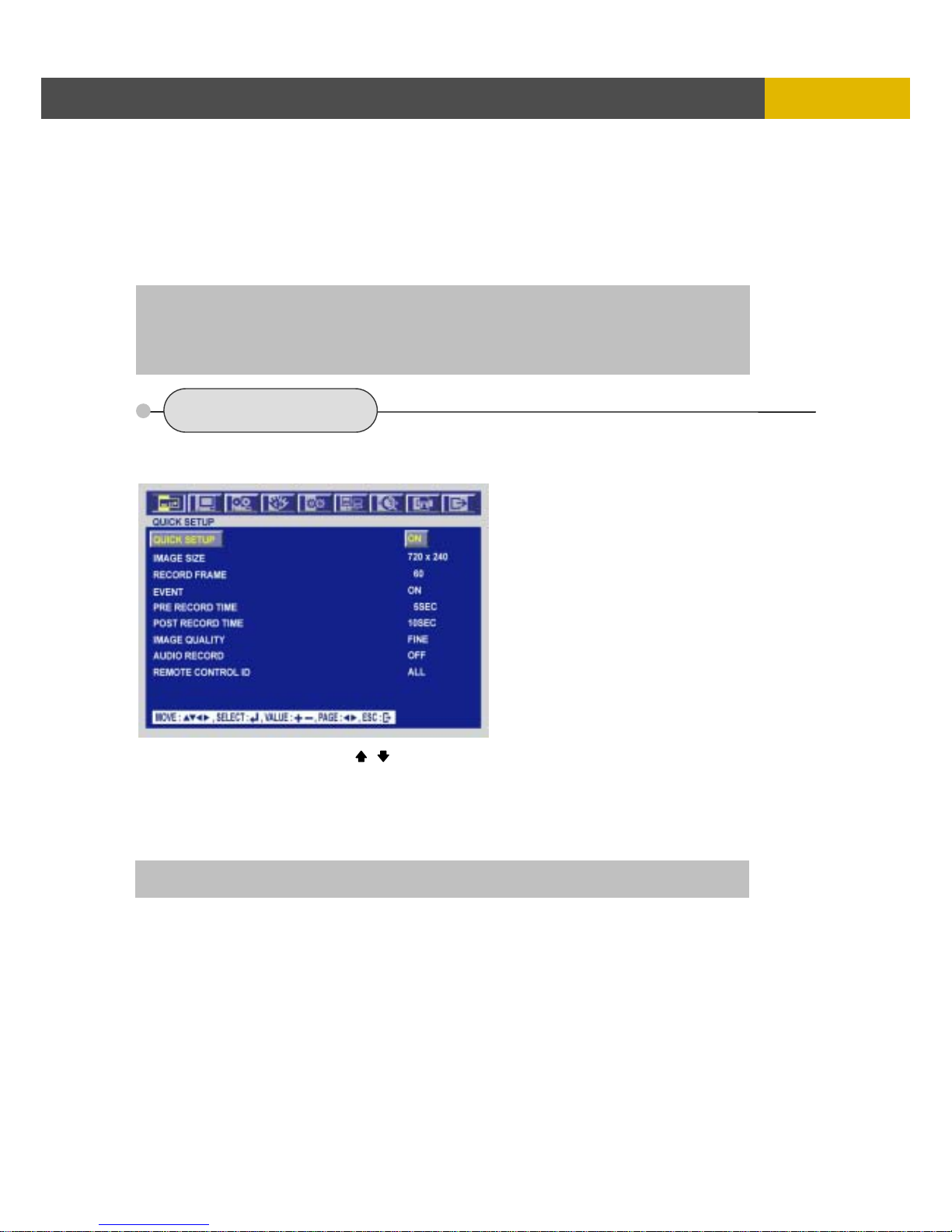
Press the MENU button and the QUICK SETUP menu appears as the following picture.
** This menu is simply used when user want to change just a few important settings.
Select the desired item using the , buttons and set up the value using the (-), (+) buttons.
6.1.1 QUICK SETUP
Select “ON” or “OFF” using the (-), (+) buttons to use the QUICK SETUP setting.
6.1.2 IMAGE SIZE
Select the desired IMAGE SIZE for recording using the (-), (+) buttons.
6.1.3 RECORD FRAME
Select the desired frame rate for normal recording using the (-), (+) buttons.
All event channels will be recorded by the setting RECORD FRAME/ 16(in case of 16CH DVR).
For example, if you set RECORD FRAME to 120, 16 each channel will be recorded by 7 ips.
** Please refer to chapter 6.3 RECORD.
You can use the mouse instead of buttons on the front panel of DVR.
Simply click the desired icon or item in case of using the mouse.
If there is no input for 1 minute during the menu screen display, the menu screen will be
closed automatically without saving of changed value.
NOTE : If you select “ON”, RECORD MENU will be disregarded.
Page 40

USER’S MANUAL
40
MENU SETUP
6.1.4 EVENT
Select a kind of EVENT using the (-), (+) buttons.
If you want to select all kind of event, choose “ALL” and if you don’t want event recording, choose
“OFF”.
The default is “ALL”.
6.1.5 PRE RECORD TIME
Select the desired time for pre-recording using the (-), (+) buttons.
When video loss, alarm or motion is detected, the DVR will store pre-recorded data during the
selected time.
The pre-recording time can be set from 0 second to 5 second and the default is “5”.
6.1.6 POST RECORD TIME
Select the desired time for post-recording using the (-), (+) buttons.
When video loss, alarm or motion is detected, the DVR will store post-recorded data during the
selected period.
The post-recording time can be set from 0 second to 60 second and the default is “10”.
6.1.7 IMAGE QUALITY
Select the desired image quality using the (-), (+) buttons.
There are 3 kinds of image quality.
Please refer to chapter 6.3 RECORD.
6.1.8 AUDIO RECORD
Select “ON” or “OFF” using the (-), (+) buttons to record audio.
6.1.9 REMOTE CONTROL ID
Refer to 6.5.5
NOTE: The pre- and post- recording is not valid in normal recording mode.
NOTE: Divide event type into three classes(alarm, loss, motion).
Page 41
DIGITAL VIDEO RECORDER
41
M
ENU SETUP
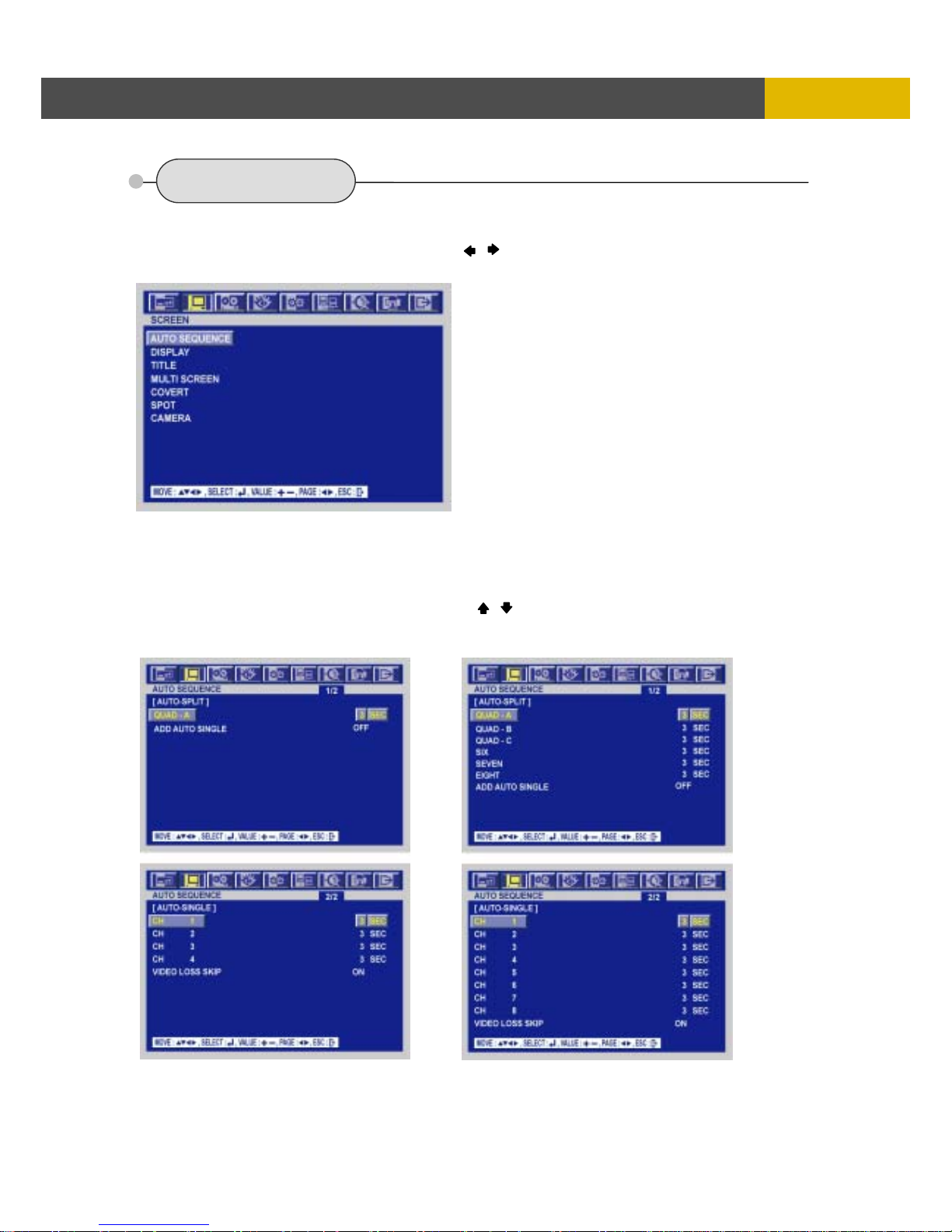
6.2 SCREEN
To set up the SCREEN menu,
① Move the cursor to the SCREEN icon using the , buttons in the MENU screen.
② Press the ENTER button when the cursor is on the SCREEN icon and the following items appear.
6.2.1 AUTO SEQUENCE
At the SCREEN menu,
① Move the cursor to the AUTO SEQUENCE using , buttons.
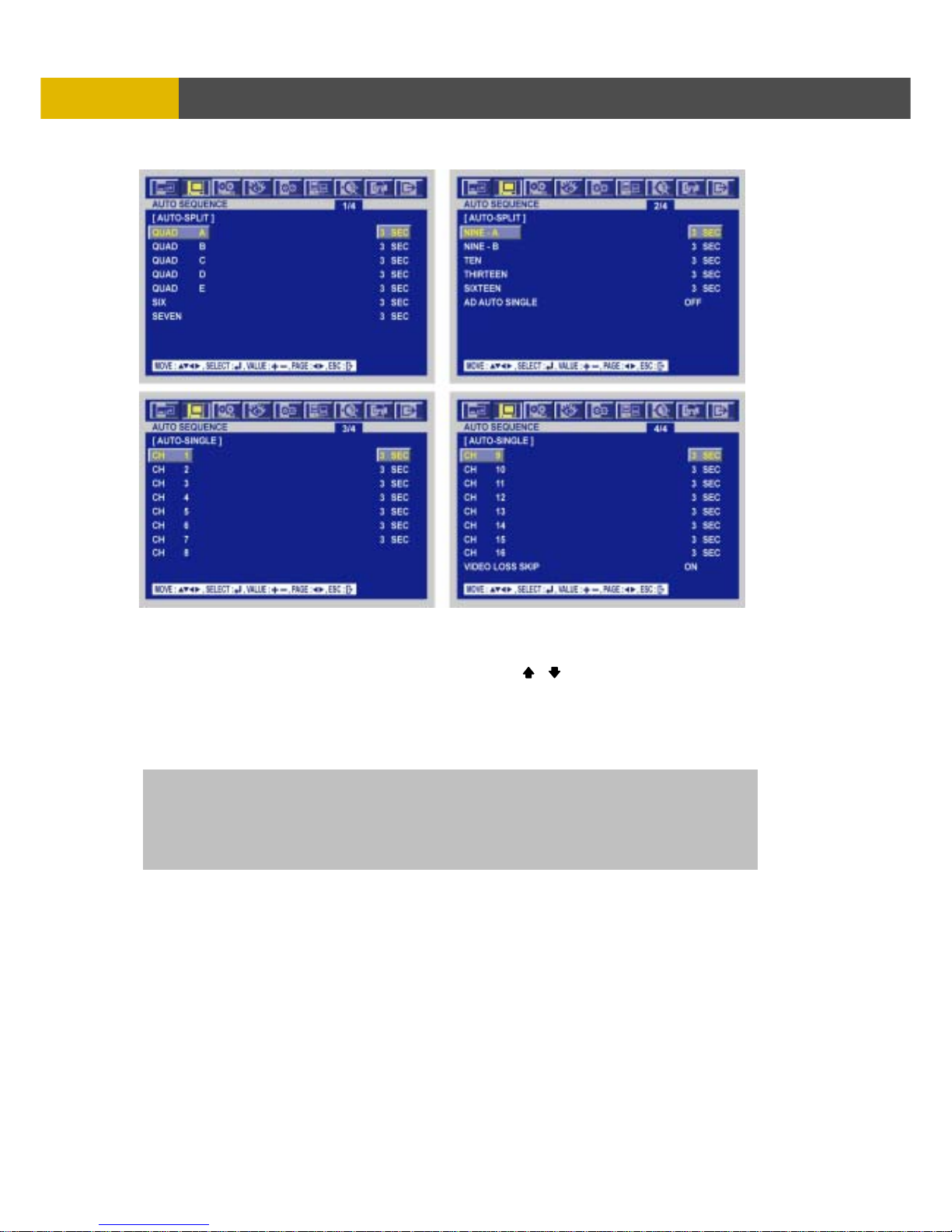
② Press the ENTER button when the cursor is on the AUTO SEQUENCE and the following screens
appear. (It’s different from models)
[ 4CH DVR ] [ 8CH DVR ]
Page 42
USER’S MANUAL
42
MENU SETUP
③ Move the cursor to each single or split channel using the , buttons.
④ When the desired channel is selected, change the value of AUTO SEQUENCE duration using
the (-), (+) buttons to set the length of time for switching each channel in sequence.
* The value is from 1SEC to 60SEC and the default is “3SEC”.
⑤ To exit this AUTO SEQUENCE menu, press the ESC button.
VIDEO LOSS SKIP : If selected ON, every VIDEO LOSS channel will be skipped in
the AUTO SEQUENCE mode. The default is “ON”.
ADD AUTO SINGLE: If selected OFF, every single channel will be skipped in
the AUTO SEQUENCE mode.
The default is “OFF”.
[ 16CH DVR ]
Page 43
DIGITAL VIDEO RECORDER
43
M
ENU SETUP
6.2.2 DISPLAY
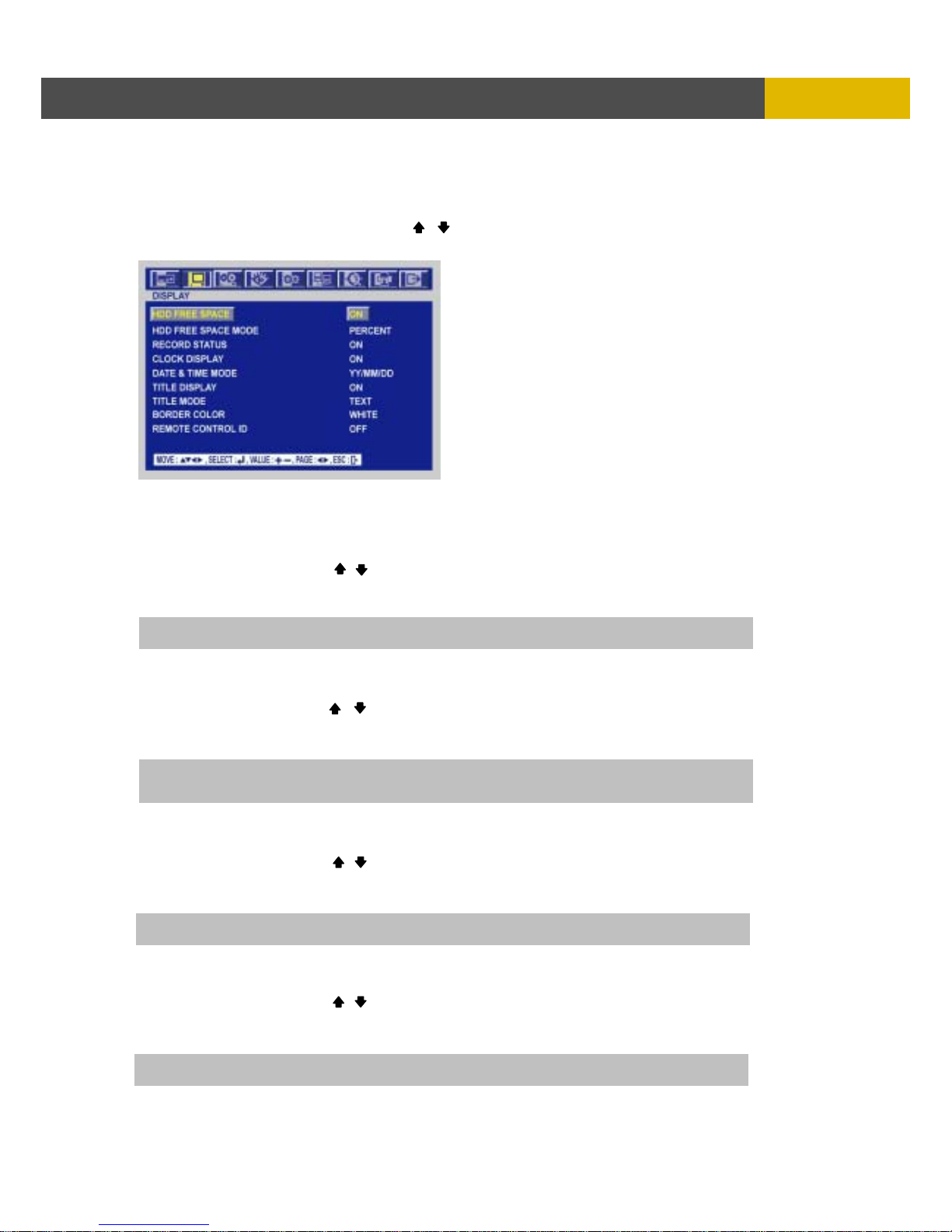
At the SCREEN menu,
① Move the cursor to the DISPLAY using , buttons.
② Press the ENTER button when the cursor is on the DISPLAY and the following items appear.
③ To exit this DISPLAY menu, press the ESC button.
6.2.2.1 HDD FREE SPACE
At the DISPLAY menu,
① Move the cursor using the , buttons to select the HDD FREE SPACE.
② Use the (-), (+) buttons to choose “ON” or “OFF”.
* The default is “ON”.
6.2.2.2 HDD FREE SPACE MODE
At the DISPLAY menu,
① Move the cursor using the , buttons to select the HDD FREE SPACE MODE.
② Use the (-), (+) buttons to choose “PERCENT” or “GIGABYTE”.
* The default is “PERCENT”.
6.2.2.3 RECORD STATUS
At the DISPLAY menu,
① Move the cursor using the , buttons to select the RECORD STATUS.
② Use the (-), (+) buttons to choose “ON” or “OFF”.
* The default is “ON”.
6.2.2.4 CLOCK DISPLAY
At the DISPLAY menu,
① Move the cursor using the , buttons to select the CLOCK DISPLAY.
② Use the (-), (+) buttons to choose “ON” or “OFF”.
* The default is “ON”.
ON: Remaining capacity of the fixed(not backup) HDDs will be displayed on the screen.
ON: The date and time will be displayed on the screen.
PERCENT: Remaining capacity of the fixed HDDs will be displayed on the screen in percent.
GIGABYTE: Remaining capacity of the fixed HDDs will be displayed on the screen in gigabyte.
ON: Displaying the recording status of each channel on the screen.
Page 44

USER’S MANUAL
44
MENU SETUP
6.2.2.5 DATE&TIME MODE
At the DISPLAY menu,
① Move the cursor using the , buttons to select the DATE&TIME MODE.
② Use the (-), (+) buttons to choose “MM/DD/YY”, “DD/MM/YY” or “YY/MM/DD”.
* The default is “YY/MM/DD”.
6.2.2.6 TITLE DISPLAY
At the DISPLAY menu,
① Move the cursor using the , buttons to select the TITLE DISPLAY.
② Use the (-), (+) buttons to choose “ON” or “OFF”.
* The default is “ ON”.
6.2.2.7 TITLE MODE
At the DISPLAY menu,
① Move the cursor using the , buttons to select the TITLE MODE.
② Use the (-), (+) buttons to choose “TEXT” or “BITMAP”.
* The default is “ TEXT”.
6.2.2.8 BORDER COLOR
At the DISPLAY menu,
① Move the cursor using the , buttons to select the BORDER COLOR.
② Use the (-), (+) buttons to choose “WHITE” or “BLACK”.
* The default is “WHITE”.
6.2.2.9 REMOTE CONTROL ID
At the DISPLAY menu,
① Move the cursor using the , buttons to select the REMOTE CONTROL ID.
② Use the (-), (+) buttons to choose “ON” or “OFF”.
* The default is “OFF”.
YY/MM/DD : All date and time will be displayed in numbers.
Ex. 2005/01/01 00:00:00
MM/DD/YY : the month section will be displayed in character.
Ex. JAN. 01 2005 00:00:00
DD/MM/YY : the day section will be displayed in character.
Ex. 01. JAN 2005 00:00:00
ON: Each channel title will be displayed on the screen. (Please refer to 6.2.3 TITLE setup)
WHITE: The color of the border line will be displayed on the multi-channel screen in white.
BLACK: The color of the border line will be displayed on the multi-channel screen in black.
ON: The remote controller ID will be displayed on the screen.
A bitmap is a type of graphics file on a computer. You can make characters with bitmap on the setup
window of network client viewer after connecting the computer with DVR. Please refer to 11.8.4.
Page 45
DIGITAL VIDEO RECORDER
45
M
ENU SETUP
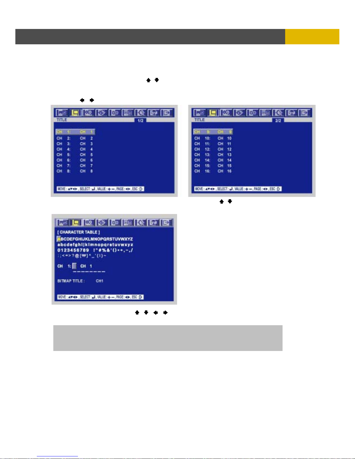
6.2.3 TITLE
At the SCREEN menu,
① Move the cursor to the TITLE using , buttons.
② Press the ENTER button when the cursor is on the TITLE and the following 2 pages screen
appears.
③ Use the , buttons to see the next page.
④ Press the ENTER button after selecting desired channel using the , buttons and the
following screen appears.
⑤ Select the character using the , , , buttons and then press the ENTER button.
⑥ To exit this CHARACTER TABLE screen, press the ESC button.
CHANNEL TITLE MODE: There are “TEXT” and “BITMAP”.
TEXT: Using the CHARACTER TABLE
BITMAP: It is possible to download new characters using the client software if you want.
Page 46
USER’S MANUAL
46
MENU SETUP
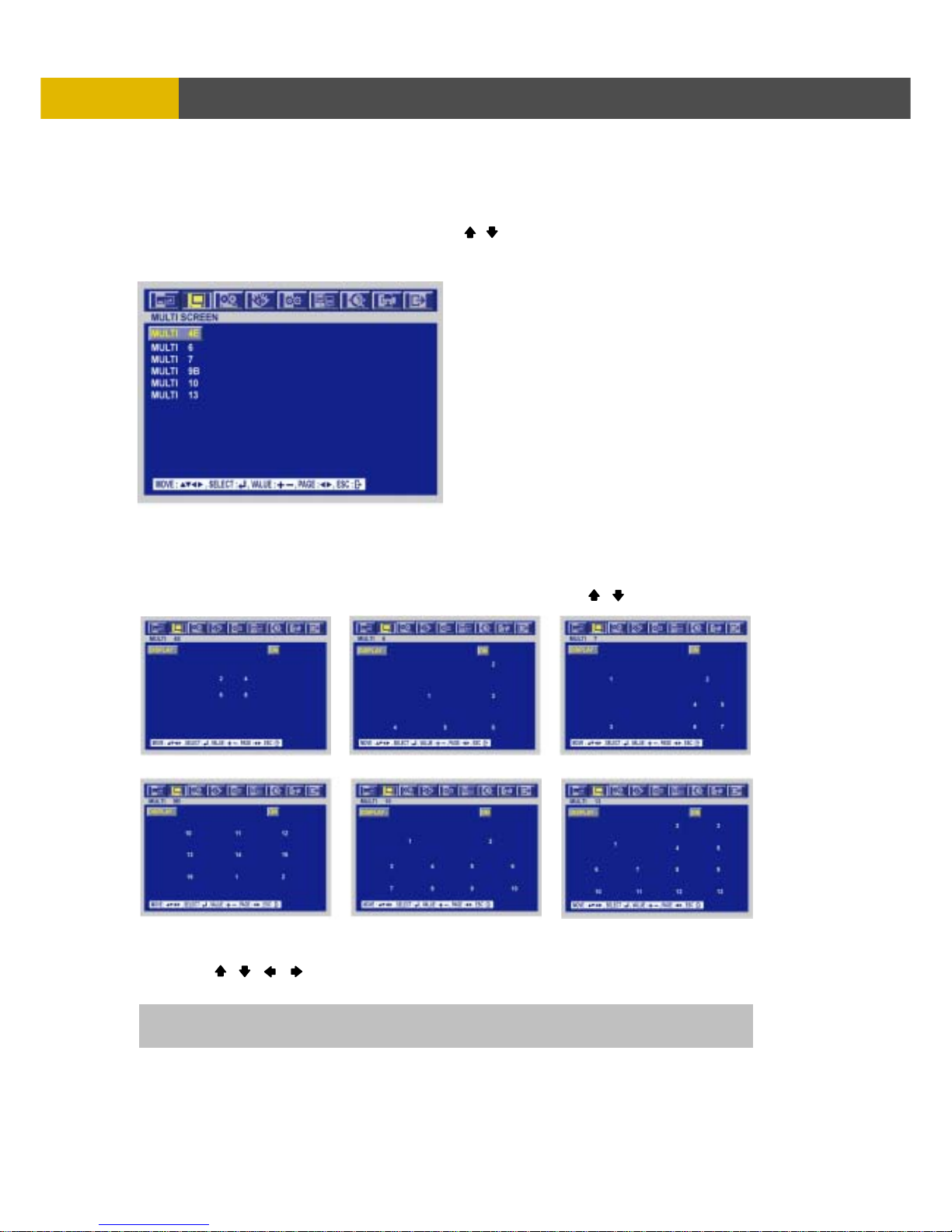
6.2.4 MULTI SCREEN
You can select the desired channels and make a 4 split screen and a 9 split screen using this menu.
At the SCREEN menu,
① Move the cursor to the MULTI SCREEN using , buttons.
② Press the ENTER button when the cursor is on the MULTI SCREEN and the following screen
appears.
③ To exit this MULTI SCREEN menu, press the ESC button.
6.2.4.1 MULTI 4E / MULTI 6 / MULTI 7 / MULTI 9B / MULTI 10 / MULTI 13
① Press the ENTER button after selecting the desired item using the , buttons.
② Set the desired number of camera in each channel screen using the (-), (+) buttons.
③ Use the , , , buttons to set the other channel screen.
④ To exit this screen, press the ESC button.
The same camera numbers should not be selected on a multi-screen.
Page 47
DIGITAL VIDEO RECORDER
47
M
ENU SETUP
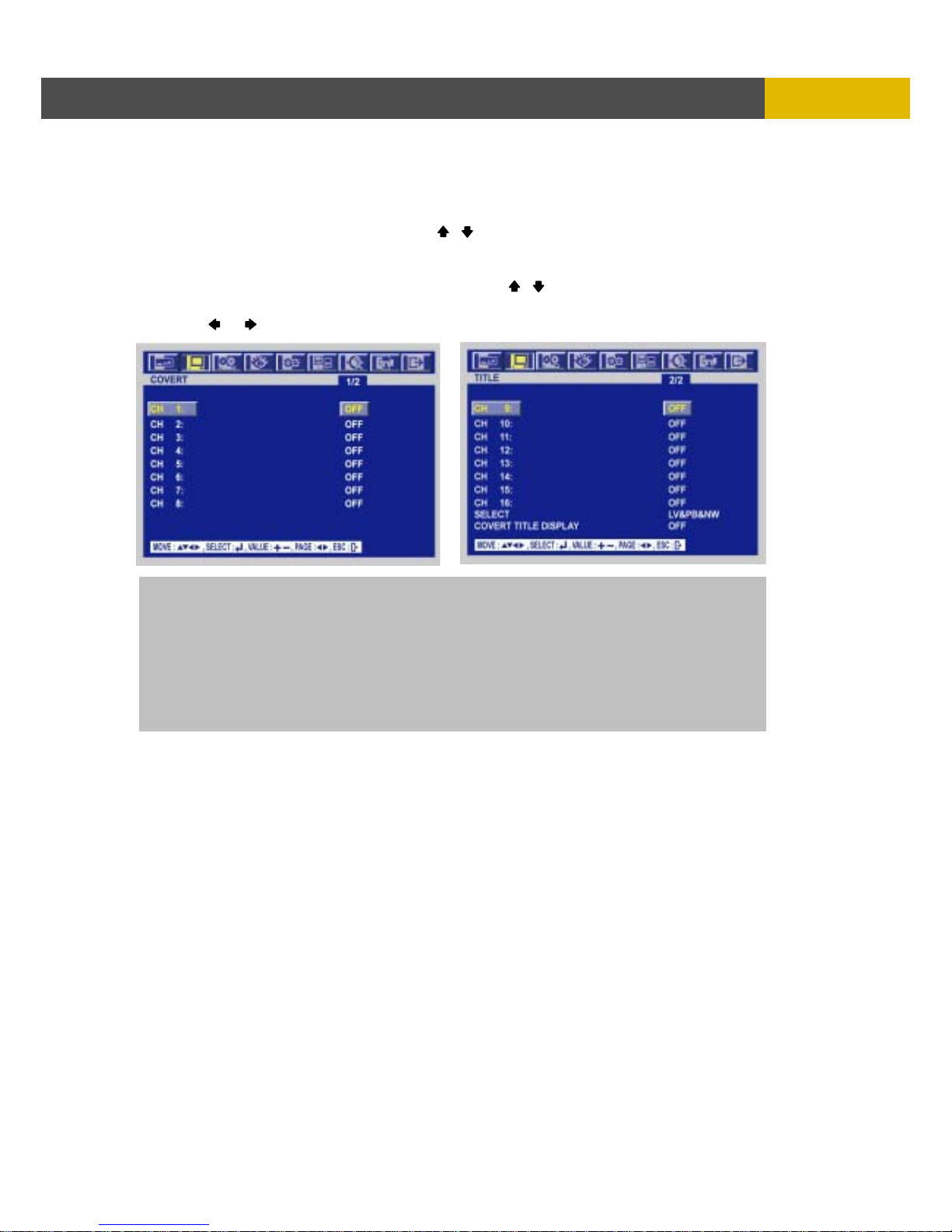
6.2.5 COVERT
At the SCREEN menu,
① Move the cursor to the COVERT using the , buttons.
② Press the ENTER button when the cursor is on the COVERT and the following 2 pages screen
appears.
③ Move the cursor and select the desired item using the , buttons.
④ Use the (-), (+) buttons to choose “ON” or “OFF”.
⑤ Use the , buttons to see the next page.
ON: Selected channel will be displayed in black screen (Hidden camera).
SELECT: It is possible to select among “LIVE&PLAYBACK&NETWORK”, “PLAYBACK&NETWORK”,
“LIVE&NETWORK”, “LIVE&PLAYBACK”, “NETWORK”, “PLAYBACK” and “LIVE”.
- LIVE: To covert selected channels on live screen
- PLAY: To covert selected channels on playback screen
- NETWORK: To covert selected channels on network viewer screen
COVERT TITLE DISPLAY : If you set “ON” on this item, the “COVERT” word will be displayed
on the covert channels.
The default is “OFF”.
Page 48
USER’S MANUAL
48
MENU SETUP
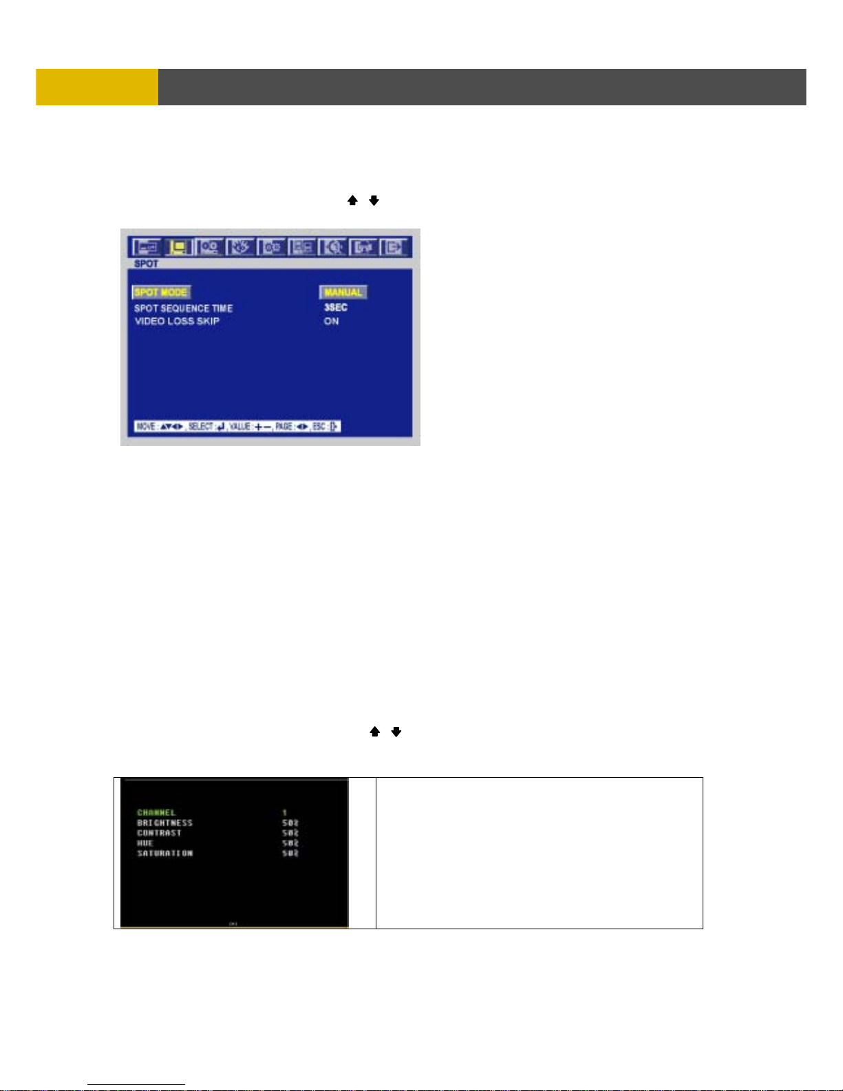
6.2.6 SPOT
At the SCREEN menu,
① Move the cursor to the SPOT using , buttons.
② Press the ENTER button when the cursor is on the SPOT and the following screen appears.
③ To exit this SPOT menu, press the ESC button.
6.2.6.1 SPOT MODE
Use the (-), (+) buttons to select the SPOT MODE.
- MANUAL: Manually select the channel of spot monitor.
- EVENT: Event channel will be displayed automatically on spot monitor.
- SEQUENCE: Every single channel will be switching and displaying in sequence.
6.2.6.2 SPOT SEQUENCE TIME
Use the (-), (+) buttons to set the SPOT SEQUENCE TIME.
The duration of spot sequence can be set from 1SEC to 60SEC.
6.2.6.3 VIDEO LOSS SKIP
Select “ON” or “OFF” using the (-), (+) buttons
If you select “ON”, loss images will be skipped.
6.2.7 CAMERA
At the SCREEN menu,
① Move the cursor to the CAMERA using , buttons.
② Press the ENTER button when the cursor is on the CAMERA and the following screen appears.
You can control brightness, contrast, hue and
saturation of each camera.
The default is 50%.
Page 49
DIGITAL VIDEO RECORDER
49
M
ENU SETUP
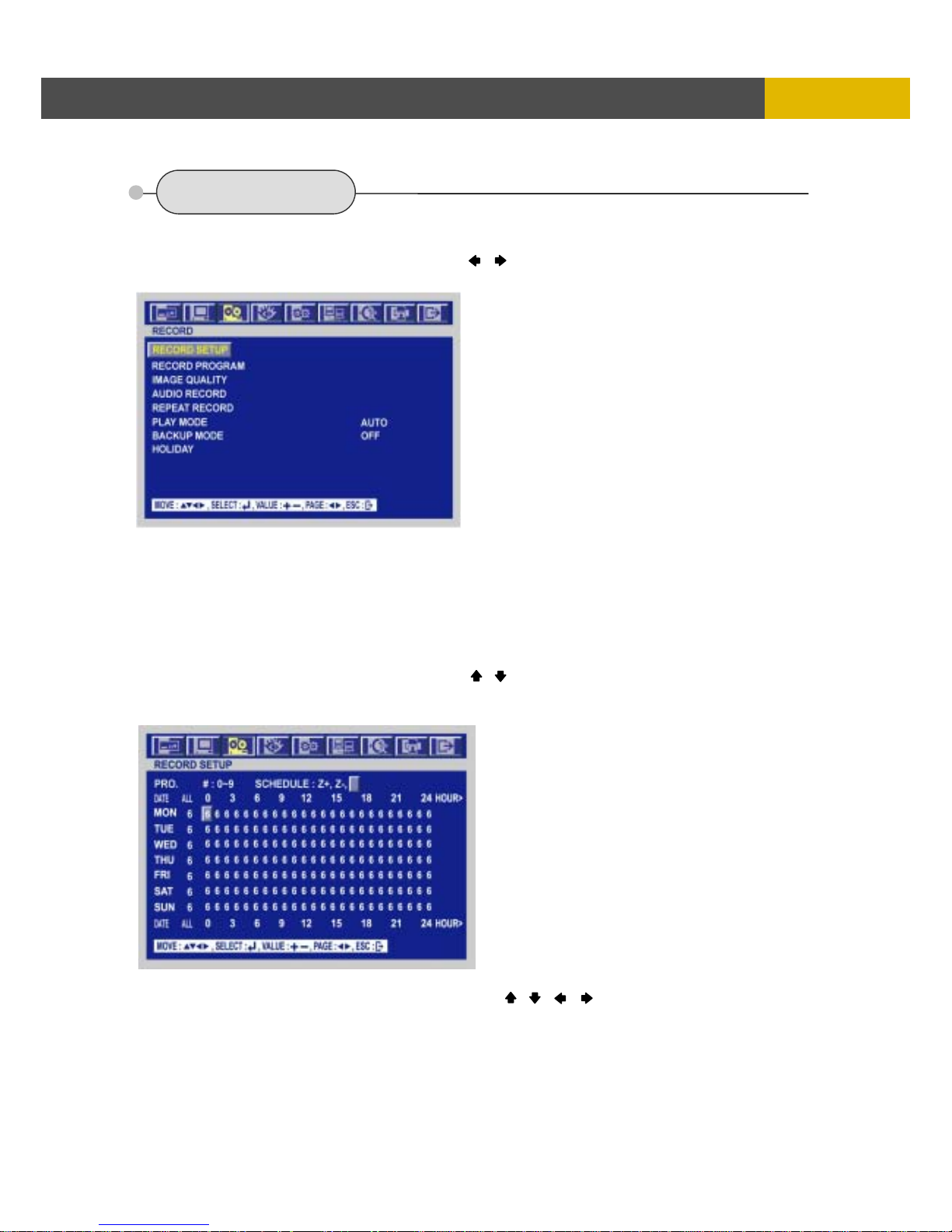
6.3 RECORD
To set up the RECORD menu,
① Move the cursor to the RECORD icon using the , in the MENU screen.
② Press the ENTER button when the cursor is on the RECORD icon and the following items appear.
6.3.1 RECORD SETUP
This menu allows you to configure a weekly recording schedule. In the schedule you must
use the predefined programs ( 0-9 ) in order to set up the recording properly. You can use
and combine different predefined programs during the week according with your own needs.
( See RECORD PROGRAM section for more information )
At the RECORD menu,
① Move the cursor to the RECORD SETUP using , buttons.
② Press the ENTER button when the cursor is on the RECORD SETUP and the following screen
appears.
③ Move the cursor to choose the desired time using the , , , buttons.
④ Select the desired program among PROGRAM 0~9.
⑤ Or move the cursor to the desired position and then click the black square next to “SCHEDULE”
using the Mouse.
⑥ Press the ESC button to exit this RECORD SETUP menu or press the ENTER button to enter
the RECORD PROGRAM menu.
Page 50
USER’S MANUAL
50
MENU SETUP
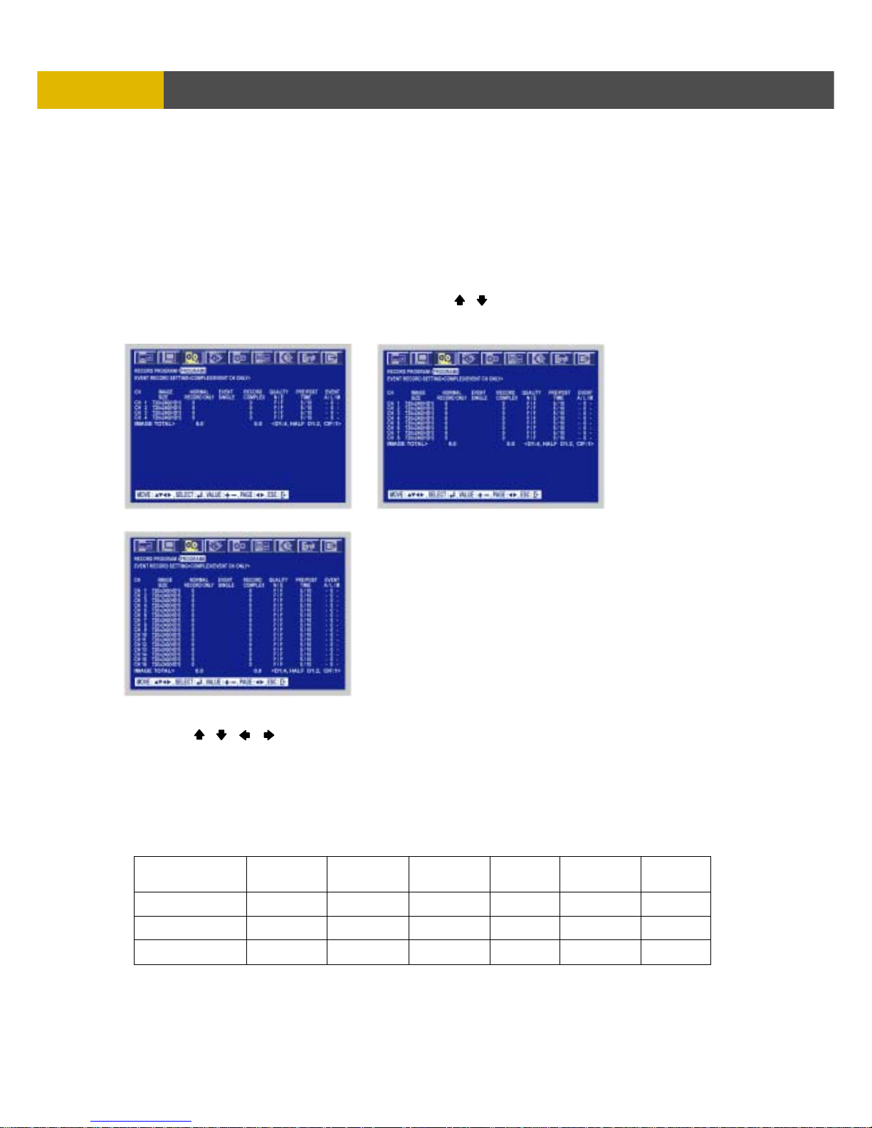
6.3.2 RECORD PROGRAM
This feature uses predefined recording modes to create new ones according with your own
needs. This means you can create different programs using existing predefined programs.
You can have up to 10 different programs (0~9) available. These programs will be used to set
up the recording schedule on the RECORD SETUP menu. For example, you can create a
program for motion detection or another for continuous recording.
At the RECORD menu,
① Move the cursor to the RECORD PROGRAM using , buttons.
② Press the ENTER button when the cursor is on the RECORD PROGRAM and the following
screen appears.
③ Use the , , , buttons to move the cursor to the desired item.
④ Select the desired RECORD TYPE using the (-), (+) buttons.
⑤ After all setting are done, exit using the ‘ESC’ key or the right-double-click of mouse.
When exiting from this menu, the DVR compute the values under this menu. And then if some
mistakes exist out of settings it will show the proper error message and return to this menu again.
And if ‘0’ IPS value is detected out of setting it will show the warning message for some seconds
and exit.
RESOLUTION
4CH
IPS/TL
IPS
per
ch ( Max)
8CH
IPS/TL
IPS
per
ch( Max)
16CH
IPS/TL
IPS
per
ch( Max)
360 x 240
CIF 120
30
CIF 120
15
CIF 120
7.5
720 x 240
D1/2 60
15
D1/2 60
7.5
D1/2 60
3.75
720 x 480
D1 30
7.5
D1 30
3.75
D1 30
1.875
[4CH DVR] [8CH DVR]
[16CH DVR]
Page 51
DIGITAL VIDEO RECORDER
51
M
ENU SETUP
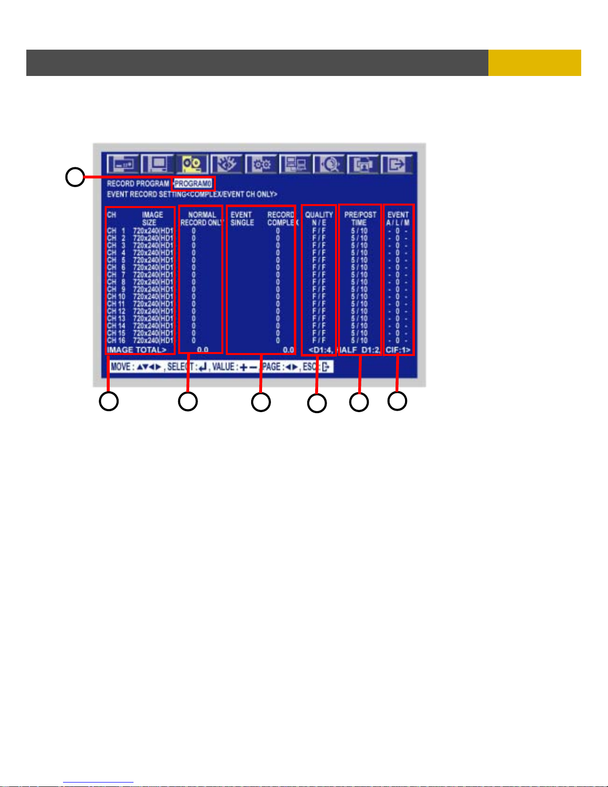
<WHAT DOES THE EACH ITEM MEANS?>
1. REC PROGRAM
Shows the current PROGRAM #. Example PROGRAM0. Select the program according with your
needs .Predefine programs are from 0 – 9.
User can choose the program number to be modified here.
2. IMAGE SIZE: Shows the actual resolution of each camera
IMAGE SIZES are : NTSC 360x240, 720x240, 720x480
PAL 360x288, 720x288, 720x576
3. NORMAL RECORD IPS: This setting allows you to configure the # of IPS for continuous
recording on each camera. The total IPS will depend on the DVR model and resolution.
The IPS value for each channel can not be over the real-time IPS.
The ‘real-time IPS’ is 30 for NTSC and 25 for PAL.
4. EVENT IPS
The EVENT recording mode will record events caused by event conditions.
These event conditions can be triggered by different events like, motion detection,
external alarm input and video loss detection.
1
2
3
4
5
6
7
Page 52

USER’S MANUAL
52
MENU SETUP
There are two types of events: SINGLE and COMPLEX.
SINGLE
EVENT CH ONLY ALL CHANNELS
Under the EVENT IPS the DVR will
record the channel triggered by any
event using the higher IPS on a
particular channel.
The rest of the channels of the
group will record based on the
NORMAL IPS set value on each
camera
Under the EVENT IPS the DVR will
record the channels triggered by any
event with the IPS value predefined or
set by the user
The rest of the channels of the group
will record sharing the remaining
NORMAL IPS among all remaining
channels.
COMPLEX
EVENT CH ONLY ALL CHANNELS
Under the EVENT IPS the DVR will
record the channels triggered by
any event .
The rest of the channels of the
group will record based on the
NORMAL IPS set value on each
camera
Note: The maximum value
between the NORMAL IPS and
the EVENT IPS determine the
allowed maximum for a channel.
The CH- SUM must not exceed
the maximum IPS of the group.
The DVR records ALL channels
triggered by events
Triggered channels use EVENT IPS
on each channel.
The rest of the channels of the group
will record based on the remaining
EVENT IPS among all remaining
channels.
EVENT CH-SUM
This item show the currently allocated sum of each channel.
(a) For SINGLE/EVENT CH ONLY
• The displayed format is ‘nn/----’.
• The value ‘nn’ of a channel means the total recording IPS of a group when the event
happens on this channel. The EVENT IPS of this channel and the sum of other channels in
a group makes this value ‘nn’.
• Any one of the CH-SUMs can not exceed the maximum IPS of a group because when event
happens with the normal record on the total IPS of a group will be the same value of this.
• ‘----‘ has no meanings.
Page 53

DIGITAL VIDEO RECORDER
53
M
ENU SETUP
(b) For SINGLE/ALL CHANNLES
• The displayed format is ‘nn/AUTO’.
• The value ‘nn’ of a channel is the recording IPS of the channel with an event.
and ‘AUTO’ means that the auto-calculated IPS of the channel when event will happen from
other channels.
• Under this mode, the ‘GROUP n SUM’ has meaning for only the NORMAL IPS and can not
exceed the maximum IPS of a group. And the total EVENT IPS is always the maximum IPS
of a group because the remains of the EVNET IPS for a channel will be allocated to other
channels evenly according to the automatic calculated value. So when event(s) happen
while the normal record is on, the maximum IPS of a group will be used.
(c) For COMPLEX/EVENT CH ONLY
• The displayed format is ‘nn/MAX’.
• The value ‘nn’ of a channel is the greater one between the NORMAL IPS and the EVENT
IPS.
• The actual event recording IPS of a channel is not the ‘nn’ but the value allocated under the
EVENT IPS.
• ‘nn’ can’t exceed the real-time IPS value.
• Because under this mode the NORMAL IPS has meaning even for the event recording
mode, the representative IPS should be the greater one.
• The total sum of all CH-SUM (GROUP n SUM of CH-SUMs) in a group can not exceed the
maximum IPS of a group.
• ‘MAX’ means the greater value of a channel between the NORMAL IPS and the
EVENT IPS. This is only the indication for user’s understanding.
(d) For COMPLEX/ALL CHANNELS
• The displayed format is ‘---/----‘.
• ‘---/----‘, CH-SUM value, has not meaning under this mode at all.
• In this case, only the ‘GROUP n SUM’s of the NORMAL IPS and the EVENT IPS have
the meaningful sum.
5. QUALITY N/E
the recording video quality for a channel.
the value under ‘N’ row is for the quality for the normal recording.
the value under ‘E’ row is for the quality for the event recording.
three step of quality exist. N means the ‘Normal Quality’, H means the ‘High Quality’ and B
means the ‘Best Quality’.
6. PRE/POST TIME
The unit of the value on this row is the second.
PRE TIME is the pre-recording duration that means how long the channel is recorded before the
event happen until the moment event issues.
POST TIME is the duration that the event channel will be recorded after the moment event issue.
PRE TIME can have the value between 0 and 5 seconds.
POST TIME can have the value between 0 and 60 seconds.
7. EVENT A/L/M
These items are the conditions under which the event recording starts
The value ‘0’ means if the ‘0’ checked event condition happen the DVR should start the event
recording for this channel and switch to the event recording mode.
The value ‘-‘ means to discard this unchecked condition as an event.
Page 54
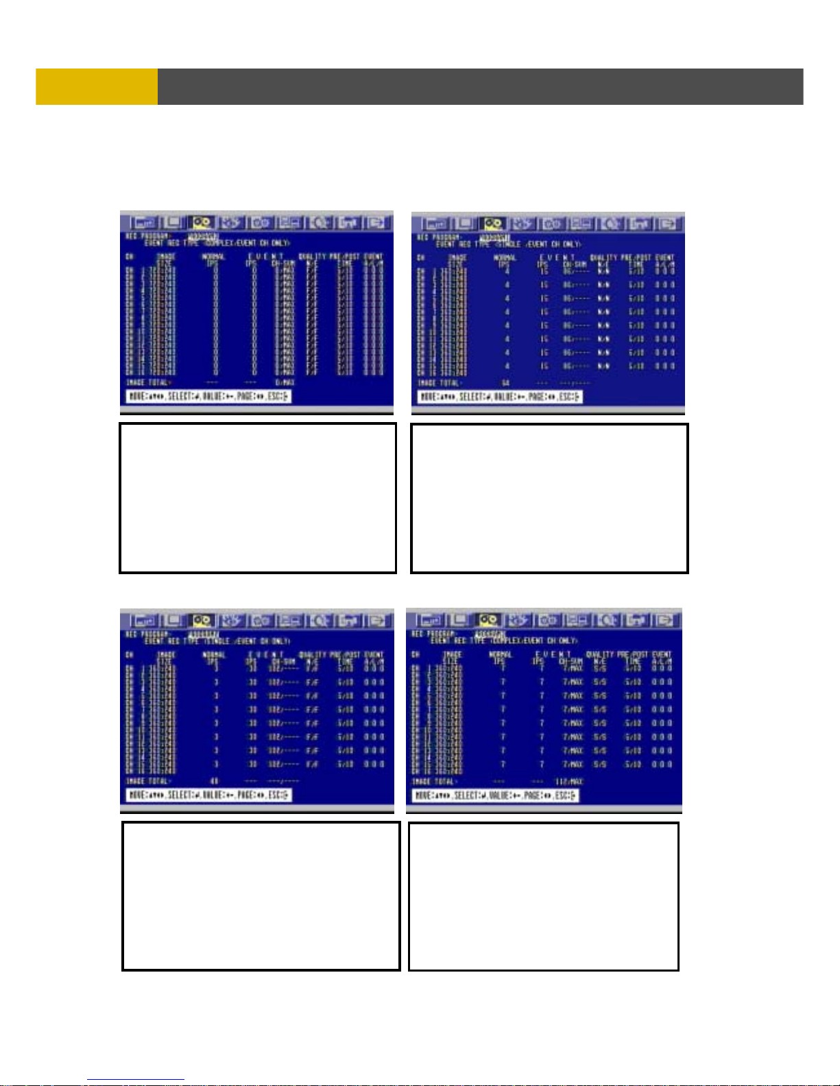
USER’S MANUAL
54
MENU SETUP
10 PREDEFINED PROGRAMS ARE INCLUDED BY DEFAULT. PROGRAMS
ARE AVAILABLE FROM 0 - 9.
PROGRAM 0. PROGRAM 1
PROGRAM 2. PROGRAM 3
FEATURES.
RECORDING MODES:
NORMAL (Continuous) : 0 ips
EVENT
COMPLEX/EVENT CH ONLY 0 ips
RESOLUTION . 720 X 240
QUALITY: F/F
PRE/POST 5/10
EVENT LOG :0 / 0 / 0. ( ALL Events= ON)
FEATURES
RECORDING MODES:
NORMAL (Continuous) : 4 fps
EVENT
SINGLE / EVENT CH ONLY 15 fps
RESOLUTION . 360 X 240 CIF
QUALITY: L/L
PRE/POST 5/10
EVENT LOG : 0 / 0 / 0. ( ALL Events= ON)
FEATURES.
RECORDING MODES:
NORMAL (Continuous) : 3 ips
EVENT
SINGLE /EVENT CH ONLY 30 ips
RESOLUTION . 360 X 240
QUALITY: F/F
PRE/POST 5/10
EVENT LOG :0 / 0 / 0.
(
ALL Events= ON
)
FEATURES.
RECORDING MODES:
NORMAL (Continuous) : 7 ips
EVENT
COMPLEX/EVENT CH ONLY 7 ips
RESOLUTION . 360 X 240
QUALITY: S/S
PRE/POST 5/10
EVENT LOG :0 / 0 / 0.
(
ALL Events= ON)
Page 55
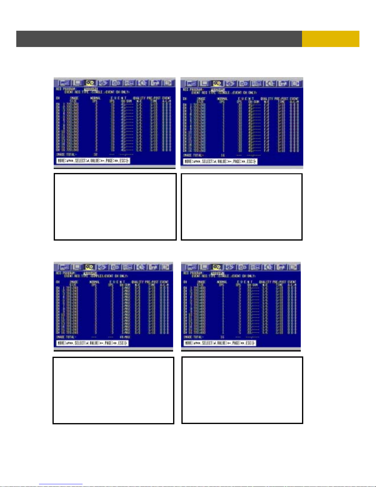
DIGITAL VIDEO RECORDER
55
M
ENU SETUP
PROGRAM 4. PROGRAM 5
PROGRAM 6. PROGRAM 7
FEATURES.
RECORDING MODES:
NORMAL (Continuous) : 2 ips
EVENT
SINGLE /EVENT CH ONLY 15 ips
RESOLUTION . 720 X 240
QUALITY: L/L
PRE/POST 5/10
EVENT LOG :0 / 0 / 0.
(
ALL Events= ON
)
FEATURES.
RECORDING MODES:
NORMAL (Continuous) : 1 ips
EVENT
SINGLE /EVENT CH ONLY 30 ips
RESOLUTION . 720 X 240
QUALITY: F/F
PRE/POST 5/10
EVENT LOG :0 / 0 / 0.
(
ALL Events= ON)
FEATURES.
RECORDING MODES:
NORMAL (Continuous) : 3 ips
EVENT
COMPLEX /EVENT CH ONLY 3 ips
RESOLUTION . 720 X 240
QUALITY: S/S
PRE/POST 5/10
EVENT LOG :0 / 0 / 0.
(
ALL Events= ON
)
FEATURES.
RECORDING MODES:
NORMAL (Continuous) : 1 ips
EVENT
SINGLE /EVENT CH ONLY 5 ips
RESOLUTION . 720 X 480
QUALITY: L/L
PRE/POST 5/10
EVENT LOG :0 / 0 / 0.
(
ALL Events= ON)
Page 56

USER’S MANUAL
56
MENU SETUP
PROGRAM 8. PROGRAM 9
< Pre-defined PROGRAM table by default>
- These are 10 kinds of program and you can change the program setting.
- The program 0 is used for the QUICK SETUP as well when QUCIK SETUP is ON.
6.3.3 IMAGE QUALITY
PROGRAM 0 1 2 3 4 5 6 7 8 9
COMPLEX SINGLE SINGLE COMPLEX SINGLE SINGLE COMPLEX SINGLE SINGLE COMPLEX
RECORD
RECORD
SETTING
EVENT
CH
ONLY
EVENT
CH
ONLY
EVENT
CH
ONLY
EVENT
CH
ONLY
EVENT
CH
ONLY
EVENT
CH
ONLY
EVENT
CH
ONLY
EVENT
CH
ONLY
EVENT
CH
ONLY
EVENT
CH
ONLY
IMAGE
SIZE
720x240 360x240 360x240 360x240 720x240 720x240 720x240 720x480 720x480 720x480
NORMAL 0 4 3 7 2 1 3 1 1 1
EVENT
SINGLE
0 15 30 0 15 30 0 5 10 0
EVENT
COMPLEX
0 0 0 7 0 0 3 0 0 1
CH - SUM 0 / MAX 86 / - 102 / - 7 / MAX 45 / - 45 / - 3 / MAX 20 / - 25 / - 1 / MAX
QUALITY
NORMAL
F L F S L F S L F S
QUALITY EVENT F L F S L F S L F S
PRE-ALARM
RECORDING
5 5 5 5 5 5 5 5 5 5
POST-ALARM
RECORDING
10 10 10 10 10 10 10 10 10 10
EVENT ON/OFF AL L ON
ALL
ON
ALL
ON
ALL ON
ALL
ON
ALL
ON
ALL ON
ALL
ON
ALL
ON
ALL ON
FEATURES.
RECORDING MODES:
NORMAL (Continuous) : 1 ips
EVENT
SINGLE /EVENT CH ONLY 10 ips
RESOLUTION . 720 X 480
QUALITY: F/F
PRE/POST 5/10
EVENT LOG :0 / 0 / 0.
(
ALL Events= ON
)
FEATURES.
RECORDING MODES:
NORMAL (Continuous) : 1 ips
EVENT
COMPLEX /EVENT CH ONLY 1 ips
RESOLUTION . 720 X 480
QUALITY: S/S
PRE/POST 5/10
EVENT LOG :0 / 0 / 0.
(
ALL Events= ON)
Page 57
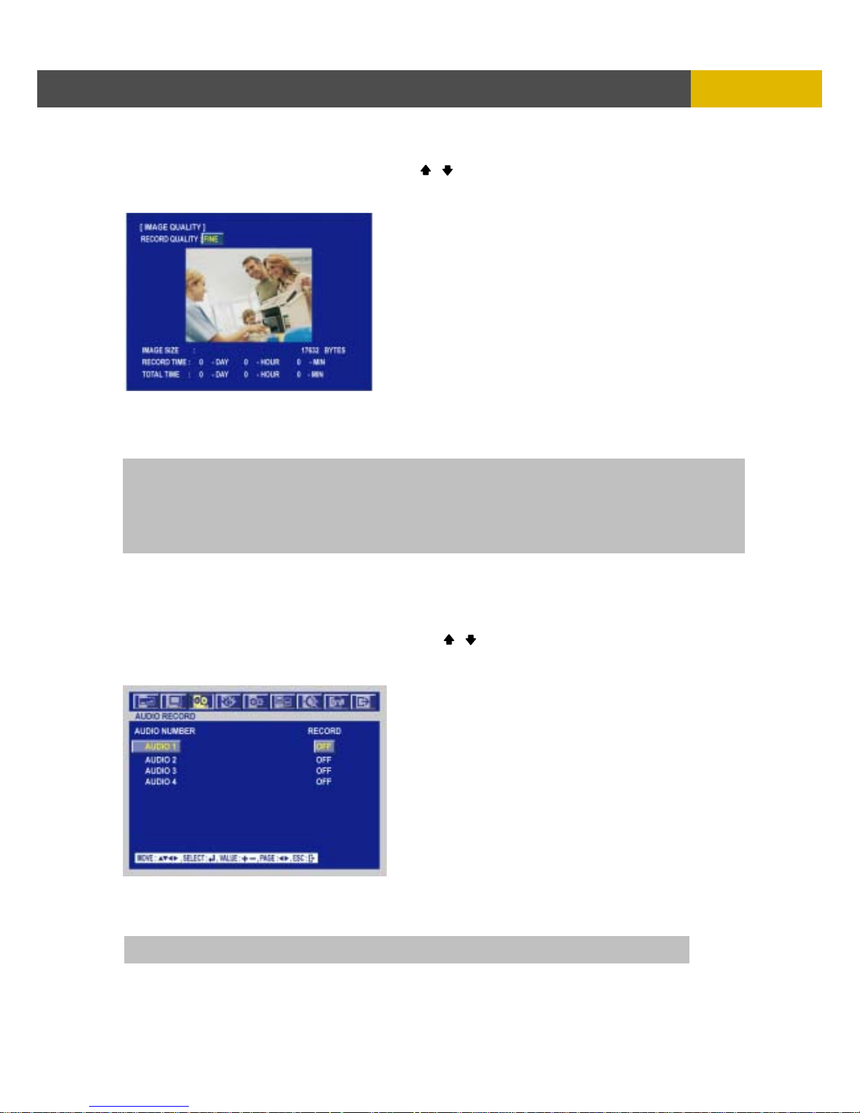
DIGITAL VIDEO RECORDER
57
M
ENU SETUP
At the RECORD menu,
① Move the cursor to the IMAGE QUALITY using , buttons.
② Press the ENTER button when the cursor is on the IMAGE QUALITY and the following screen
appears.
③ Select the desired RECORD QUALITY using the (-), (+) buttons.
④ And you can see the size of each image quality and how long you can record in the installed
HDDs by the image quality.
⑤ To exit this IMAGE QUALITY menu, press the ESC button.
6.3.4 AUDIO RECORD
At the RECORD menu,
① Move the cursor to the AUDIO RECORD using the , buttons.
② Press the ENTER button when the cursor is on the AUDIO RECORD and the following screen
appears.
③ Select the audio recording channels using the (-), (+) buttons.
④ Press the AUDIO SEL button and then press the desired channel button on the front panel after
saving this menu and you can hear the selected channel audio.
NOTE
You have to turn off the “REC” button to use the image quality menu.
RECORD TIME: A period how long you can record in free space of installed HDD(s) by setting frame rate.
TOTAL TIME: A period how long you can record in total installed HDD(s) by setting frame rate.
** The better the image quality is, the bigger the file size is and the worse the image quality,
the smaller the file size is.
NOTE : AUDIO SELECT + CHANNEL during live or playback
Page 58
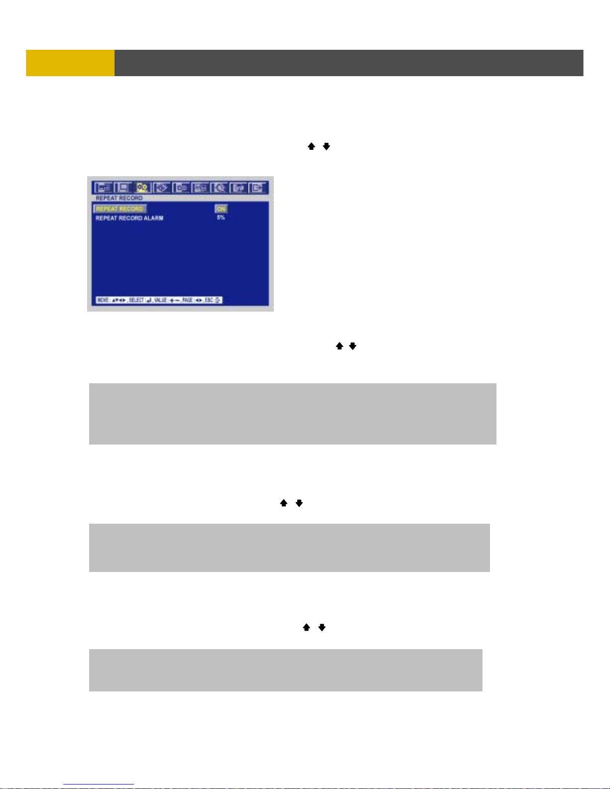
USER’S MANUAL
58
MENU SETUP
6.3.5 REPEAT RECORD
At the RECORD menu,
① Move the cursor to the REPEAT RECORD using , buttons.
② Press the ENTER button when the cursor is on the REPEAT RECORD and the following screen
appears.
③ Use the (-), (+) buttons to set “ON” or “OFF”.
④ It is possible to set a point of time to work the REPEAT RECORD ALARM.
Move the cursor to ” REPEAT RECORD ALARM” using , buttons and then select the
desired value using (-), (+) buttons.
The value is from 5% to 10% and OFF is not.
⑤ To exit this REPEAT RECORD menu, press the ESC button.
6.3.6 PLAY MODE
At the RECORD menu,
① Move the cursor to the PLAY MODE using , buttons.
② Select the PLAY MODE using the (-), (+) buttons.
6.3.7 BACKUP MODE
At the RECORD menu,
① Move the cursor to the “BACKUP MODE” using , buttons.
② Select the “BACKUP MODE” using the (-), (+) buttons.
ON: The recorded data will be overwritten when it is a point of time to work the “REPEAT RECORD”.
“REPEAT RECORD ALARM” is the rest capacity of the HDD.
If you set “REPEAT RECORD” to OFF and “REPEAT RECORD ALARM” to 5%, alarm will work when
the rest capacity of the HDD is 5%.
FRAME : It will playback images in frame mode which is useful for recorded images in high frame rate.
This may occur moving artifact with recorded images in low frame rate.
FIELD : It will playback images in field mode. This reduces the resolution, but is suitable
for recorded images in low frame rate.
EVENT : Backup only when the event occurs.
MIRROR : Recording the same images in backup HDD.
OFF : Not backup.
Page 59
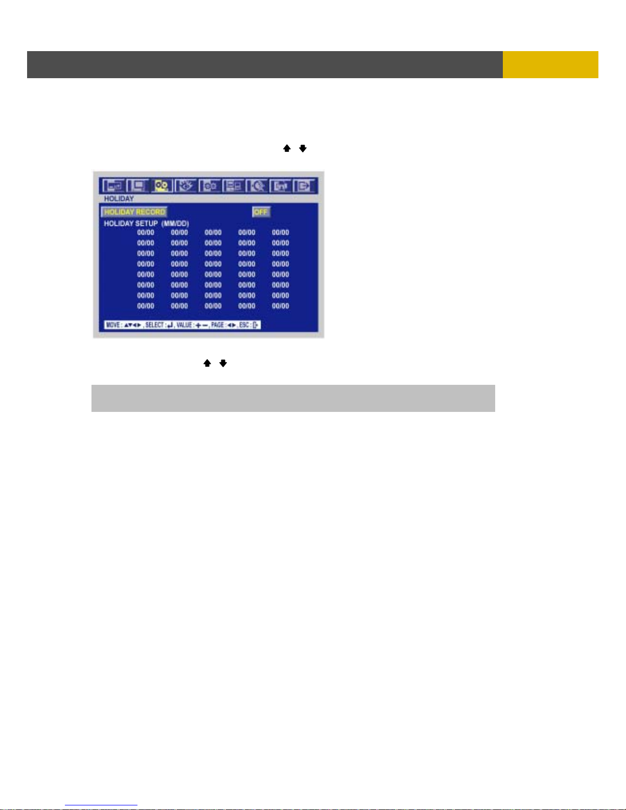
DIGITAL VIDEO RECORDER
59
M
ENU SETUP
6.3.8 HOLIDAY
At the RECORD menu,
① Move the cursor to the “HOLIDAY” using , buttons.
② Press the “ENTER” button to set up “HOLIDAY” and the HOLIDAY menu screen appears.
③ Set up “ON” or “OFF” of HOLIDAY RECORD using the (-), (+) buttons.
④ Move the cursor using , buttons and set up the value using the (-), (+) buttons.
⑤ To exit this HOLIDAY menu, press the ESC button.
NOTE: DVR will record like SUNDAY recording program on setting HOLIDAY.
Page 60
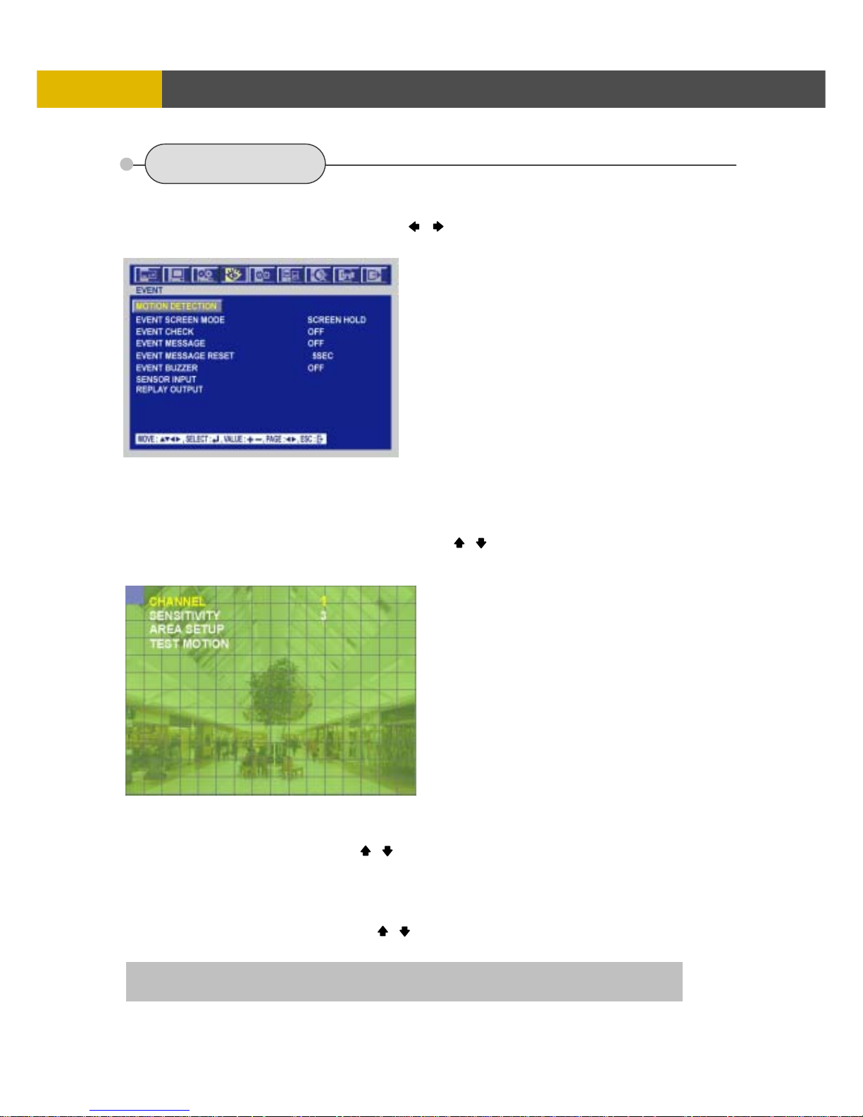
USER’S MANUAL
60
MENU SETUP
6.4 EVENT
To set up the EVENT menu,
① Move the cursor to the EVENT icon using the , in the MENU screen.
② Press the ENTER button when the cursor is on the EVENT icon and the following items appear.
6.4.1 MOTION DETECTION
At the EVENT menu,
① Move the cursor to the MOTION DETECTION using , buttons.
② Press the ENTER button when the cursor is on the MOTION DETECTION and the following
screen appears.
6.4.1.1 CHANNEL
At the MOTION DETECTION menu,
① Move the cursor to CHANNEL using , buttons.
② Select the desired channel using the (-), (+) buttons.
6.4.1.2 SENSITIVITY
At the MOTION DETECTION menu,
① Move the cursor to SENSITIVITY using , buttons.
② Select the sensitivity level using the (-), (+) buttons.
SENSITIVITY: The higher the number is, the more sensitive. 1(lowest) ~ 5(highest)
Page 61

DIGITAL VIDEO RECORDER
61
M
ENU SETUP
6.4.1.3 AREA SETUP
At the MOTION DETECTION menu,
① Move the cursor to AREA SETUP using , buttons.
② Press the ENTER button to set the motion detection area.
③ Select the motion detection area using the , , , buttons and then press the ENTER
button to save the area.
④ To exit this AREA SETUP, press the ESC button.
6.4.1.4 TEST MOTION
At the MOTION DETECTION menu,
① Move the cursor to TEST MOTION using the , buttons.
② Press the ENTER button to test the motion detection.
③ To exit this TEST MOTION, press the ESC button.
6.4.2 EVENT SCREEN MODE
At the EVENT menu,
① Move the cursor to the EVENT SCREEN MODE using , buttons.
② Select the EVENT SCREEN MODE using the (-), (+) buttons.
6.4.3 EVENT CHECK
At the EVENT menu,
① Move the cursor to the EVENT CHECK using , buttons.
② Select “ON” or “OFF” using the (-), (+) buttons.
6.4.4 EVENT MESSAGE
At the EVENT menu,
① Move the cursor to the EVENT MESSAGE using , buttons.
② Select “ON” or “OFF” using the (-), (+) buttons.
6.4.5 EVENT MESSAGE RESET
At the EVENT menu,
① Move the cursor to the EVENT MESSAGE RESET using , buttons.
② Set the time to reset the event message using the (-), (+) buttons.
ON: The warning message will be displayed when the event occurs.
SCREEN HOLD : Keeping the current screen even if the event occurs.
EVENT FULL : Display the full screen of the channel which the event occurs.
EVENT MULTI : Display the multi-screen when the event occurs.
EVENT F_RTN : Display the full screen of the channel which the event occurs and return.
EVENT M_RTN : Display the multi-screen when the event occurs and return.
NOTE: If you want to use this function, you have to set EVENT setting of each channel of
RECORD PROGRAM by “O(ON)”.
Mouse operation: Click the right button of mouse and drag to select the desired cells.
AREA SETUP GRID: 16 x 12
NOTE: If you press the PLAY button, all cells will be green and can’t detect the motion.
If you press the FAST button, all cells will be transparent and can detect the motion.
Page 62
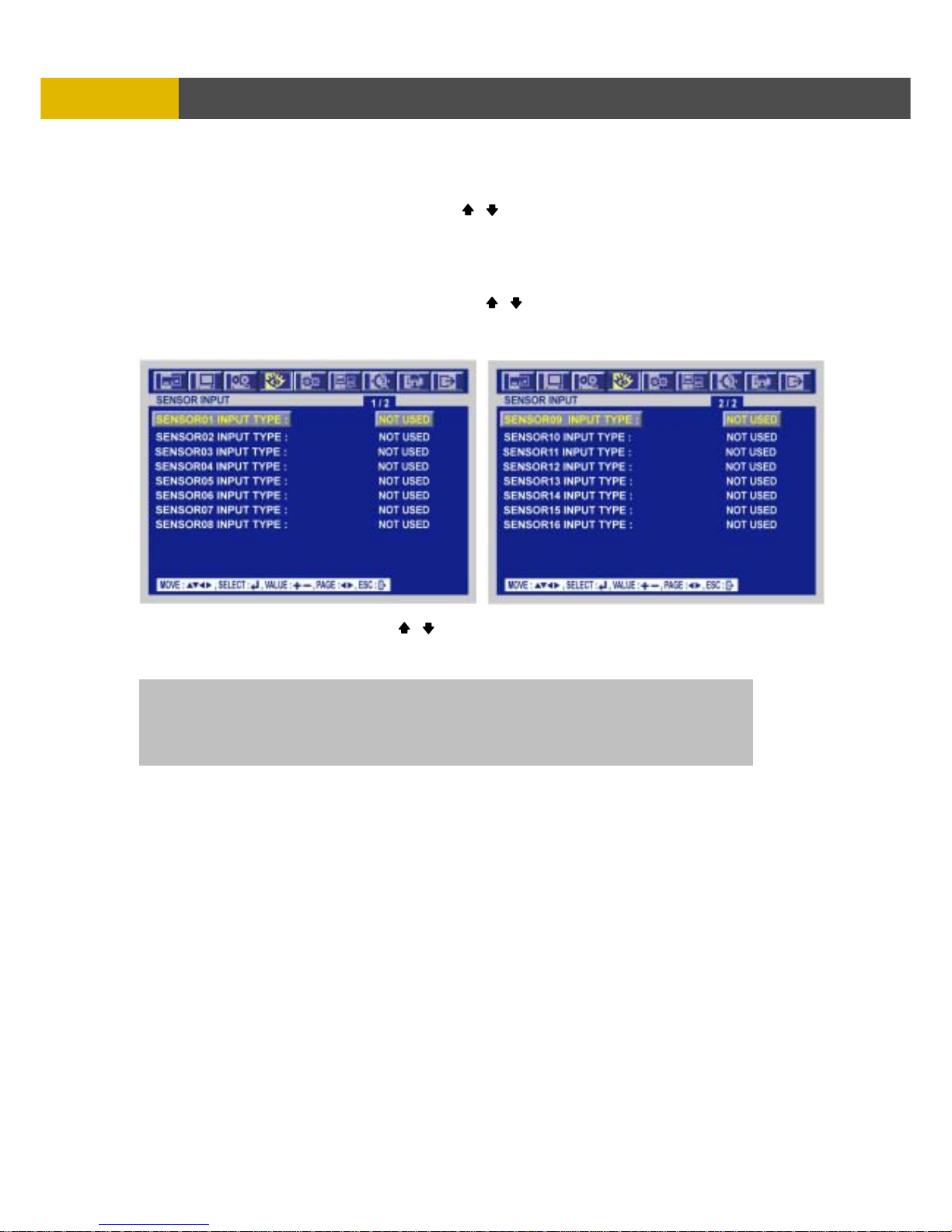
USER’S MANUAL
62
MENU SETUP
6.4.6 EVENT BUZZER
At the EVENT menu,
① Move the cursor to the EVENT BUZZER using , buttons.
② Select “ON’ or “OFF” using the (-), (+) buttons to set the event buzzer.
6.4.7 SENSOR INPUT
At the EVENT menu,
① Move the cursor to the SENSOR INPUT using the , buttons.
② Press the ENTER button when the cursor is on the SENSOR INPUT and the following 2 pages
screen appears.
③ Select the desired channel using the , buttons.
④ Select the type of sensor which is connected with DVR using the (-), (+) buttons.
⑤ To exit this SENSOR INPUT menu, press the ESC button.
Select the right sensor type according to the type of installed sensor with the unit.
NORMAL OPEN : The sensor is open in normal times.
NORMAL CLOSE : The sensor is close in normal times.
NOT INSTALLED: No sensors are connected to the DVR unit
Page 63
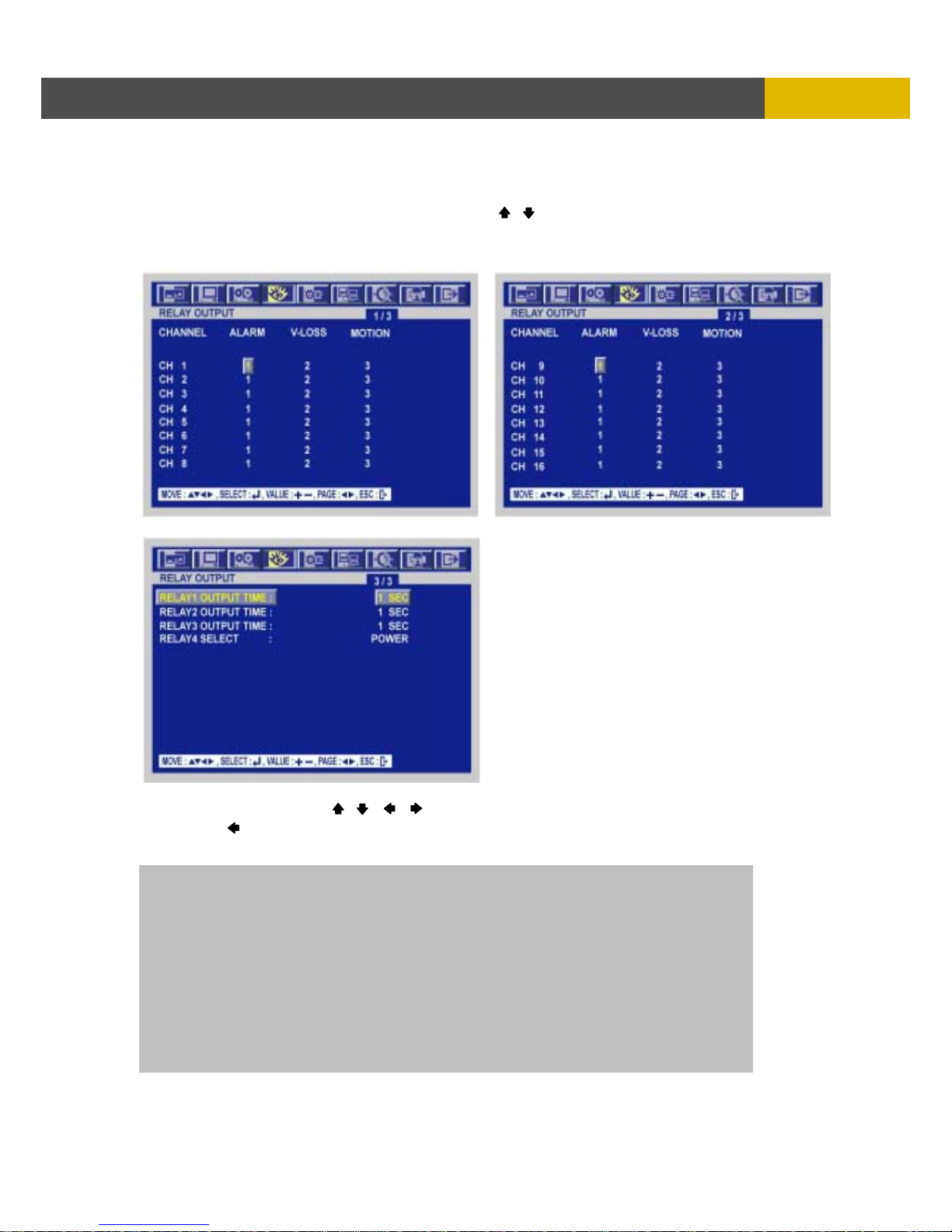
DIGITAL VIDEO RECORDER
63
M
ENU SETUP
6.4.8 RELAY OUTPUT
At the EVENT menu,
① Move the cursor to the “RELAY OUTPUT” using the , buttons.
② Press the ENTER button when the cursor is on the “RELAY OUTPUT” and the following screen
appears.
③ Move the cursor using the , , , buttons and set up the value using the (-), (+) buttons.
④ Press the button to see the next page.
⑤ To exit this screen, press the “ESC” button.
NOTE
- It is possible to set the RELAY OUTPUT of each channel in the type of event.
- Relay output is from 1 to 4 and it is possible to set the period of the relay output.
<RELAY 4 SELECT>
There are POWER, USER, NOT USED and HDD ERROR.
z POWER: The relay is working when power is off.
z USER: User can operate the relay manually.
Press the “FUNCTION” button to operate RELAY 4 manually.
NC→NO: And then press the (+) button.
NO→NC: And then press the (-) button.
Press the “FUNCTION” button again if you want to exit this mode.
(You can also use this function through network viewer.)
Page 64
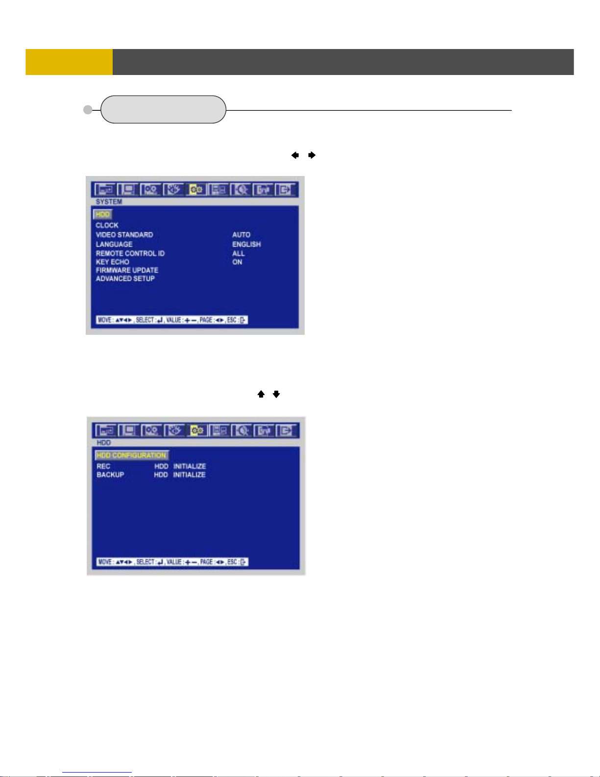
USER’S MANUAL
64
MENU SETUP
6.5 SYSTEM
To set up the SYSTEM menu,
① Move the cursor to the SYSTEM icon using the , in the MENU screen.
② Press the ENTER button when the cursor is on the SYSTEM icon and the following items appear.
6.5.1 HDD
At the SYSTEM menu,
① Move the cursor to the HDD using the , buttons.
② Press the ENTER button when the cursor is on the HDD and the following screen appears.
③ To exit this HDD menu, press the ESC button.
Page 65
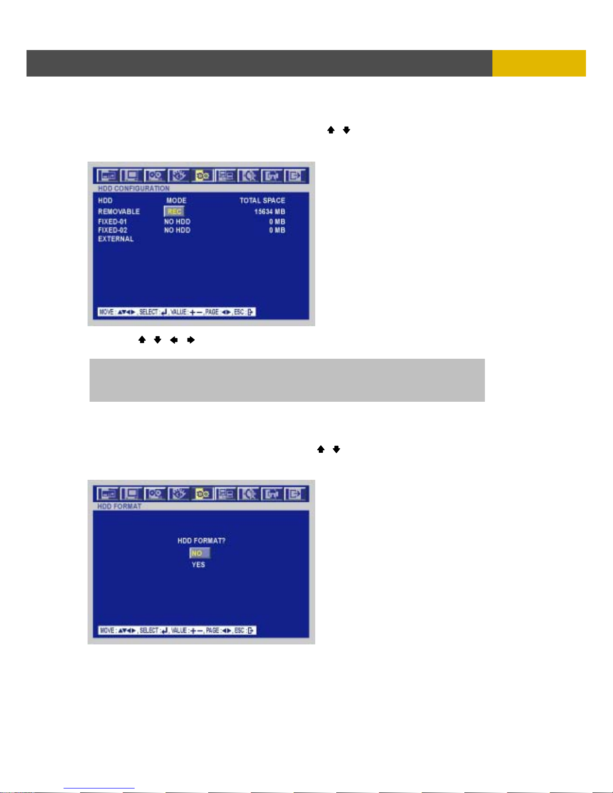
DIGITAL VIDEO RECORDER
65
M
ENU SETUP
6.5.1.1 HDD CONFIGURATION
At the HDD menu,
① Move the cursor to HDD CONFIGURATION using the , buttons.
② Press the ENTER button when the cursor is on the HDD CONFIGURATION and the following
screen appears.
③ Use the , , , buttons to move the cursor and use the (-), (+) buttons to change the
value.
6.5.1.2 REC HDD INITIALIZE
At the HDD menu,
① Move the cursor to REC HDD INITIALIZE using the , buttons.
② Press the ENTER button when the cursor is on the REC HDD INITIALIZE and the following
screen appears.
③ If you want to initialize, move the cursor to “YES” and then press the “ENTER” button.
If not, move the cursor to “NO” and then press the “ENTER” button.
④ To exit this screen, press the ESC button.
⑤ To exit this HDD menu, press the “ESC” button again.
HDD MODE
- REC: Normal and Event recording
- BACKUP: Only for backup
Page 66
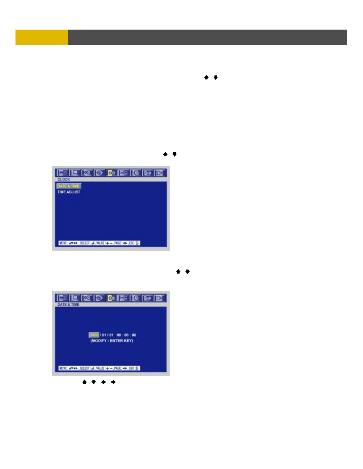
USER’S MANUAL
66
MENU SETUP
6.5.1.3 BACKUP HDD INITIALIZE
At the HDD menu,
① Move the cursor to “BACKUP HDD INITIALIZE” using the , buttons.
② Press the “ENTER” button when the cursor is on the “BACKUP HDD INITIALIZE” and the
following screen appears.
③ If you want to initialize, move the cursor to “YES” and then press the ENTER button.
If not, move the cursor to “NO” and then press the ENTER button.
④ To exit this screen, press the ESC button.
⑤ To exit this HDD menu, press the “ESC” button again.
6.5.2 CLOCK
At the SYSTEM menu,
① Move the cursor to the CLOCK using the , buttons.
② Press the ENTER button when the cursor is on the CLOCK and the following screen appears.
6.5.2.1 DATE&TIME
At the CLOCK menu,
① Move the cursor to the DATE&TIME using the , buttons.
② Press the ENTER button when the cursor is on the DATE&TIME and the following screen
appears.
③ Use the , , , buttons to move the cursor to the desired position of date or time.
④ Use the (-), (+) buttons to modify the current date and time.
- DATE: YYYY/MM/DD YEAR/MONTH/DAY
- TIME : HH:MM:SS HOUR:MINUTE:SECOND
⑤ Press the ENTER button to save the modified value.
⑥ To exit this DATE & TIME screen, press the ESC button.
Page 67
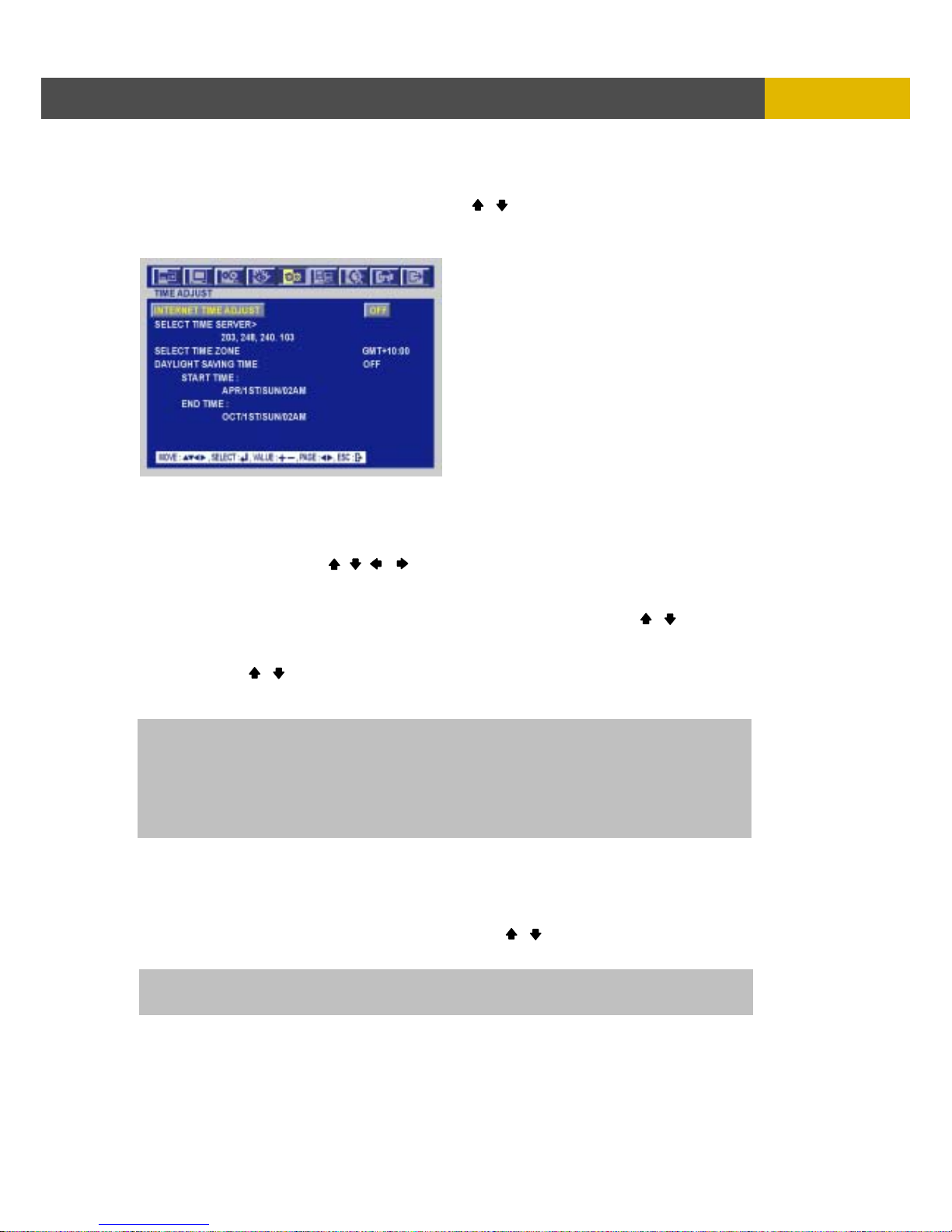
DIGITAL VIDEO RECORDER
67
M
ENU SETUP
6.5.2.2 TIME ADJUST
At the CLOCK menu,
① Move the cursor to the TIME ADJUST using the , buttons.
② Press the ENTER button when the cursor is on the TIME ADJUST and the following screen
appears.
③ Select “ON” or “OFF” using the (-), (+) buttons when the cursor is on “INTERNET TIME ADJUST”.
If the INTERNET TIME ADJUST is “ON”, the time of DVR will be adjusted to the time offered by
the internet server.
** There are 10 kinds of internet server to supply GMT in this DVR.
④ Move the cursor using the , , , buttons and then set the IP address of SELECT TIME
SERVER using the (-), (+) buttons.
⑤ Set the correct TIME ZONE standardizing GMT(Greenwich Mean Time).
⑥ Move the cursor to the DAYLIGHT SAVING TIME(Summer time) using the , buttons and
then select “ON” or “OFF” using the (-), (+) buttons.
⑦ If the DAYLIGHT SAVING TIME set “ON”, set up the starting date and time and end date and
time. Use the , buttons to move the cursor and use the (-), (+) buttons to change
the value.
⑧ To exit this TIME ADJUST menu, press the ESC button.
6.5.3 VIDEO STANDARD
At the SYSTEM menu,
① Move the cursor to the VIDEO STANDARD using the , buttons.
② Select the desired value using the (-), (+) buttons.
If you select “AUTO”, this DVR can detect NTSC/PAL automatically boot time.
The default is “AUTO”.
NOTE: If you want to use this function, you have to input DNS address.
Please refer to 6.6.1.
Manual setup: This DVR can recognize the correct time by itself. That is to say, if you input the correct
time 3 or 4 times, the DVR will recognize the clock error and display the correct time by
itself.
When you power on, you can see the TIME TRIMMING VALUE screen and modify time
correctly on this screen with AUTO button and ALARM RESET button.
Page 68
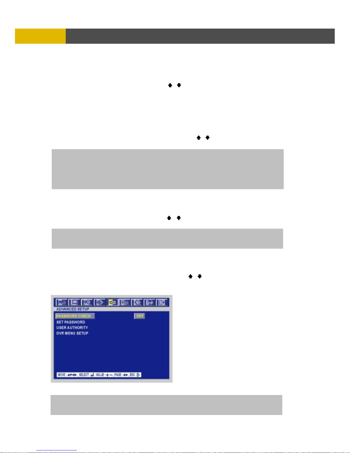
USER’S MANUAL
68
MENU SETUP
6.5.4 LANGUAGE
At the SYSTEM menu,
① Move the cursor to the LANGUAGE using the , buttons.
② Select the desired language using the (-), (+) buttons.
* Available languages: ENGLISH, KOREAN, JAPANESE , POLISH, SPANISH, RUSSIAN,
CHINESE, TAIWANESE.
6.5.5 REMOTE CONTROL ID
At the SYSTEM menu,
① Move the cursor to the REMOTE CONTROL ID using the , buttons.
② Set the REMOTE CONTROL ID using the (-), (+) buttons.
6.5.6 KEY ECHO
At the SYSTEM menu,
① Move the cursor to the KEY ECHO using the , buttons.
② Set “ON” or “OFF” using the (-), (+) buttons.
6.5.7 ADVANCED SETUP
At the SYSTEM menu,
① Move the cursor to the ADVANCED SETUP using the , buttons.
② Press the ENTER button when the cursor is on the ADVANCED SETUP and the following screen
appears.
③ To exit this ADVANCED SETUP menu, press the ESC button
If you are operating more than one DVR in the same place and wish to use the remote controller, the
remote controller ID setup is required.
Creates the Remote controller ID
Select one of ALL, 11~14, 21~24, 31~34, 41~44, and then press the same number button on the
supplied remote controller before the operation.
ON : The beep sounds when you press any buttons on the front panel.
OFF : The beep does not sound.
NOTE: In case that the PASSWORD CHECK is on, only ADMIN and MASTER can enter the
ADVANCED SETUP MENU.
Page 69
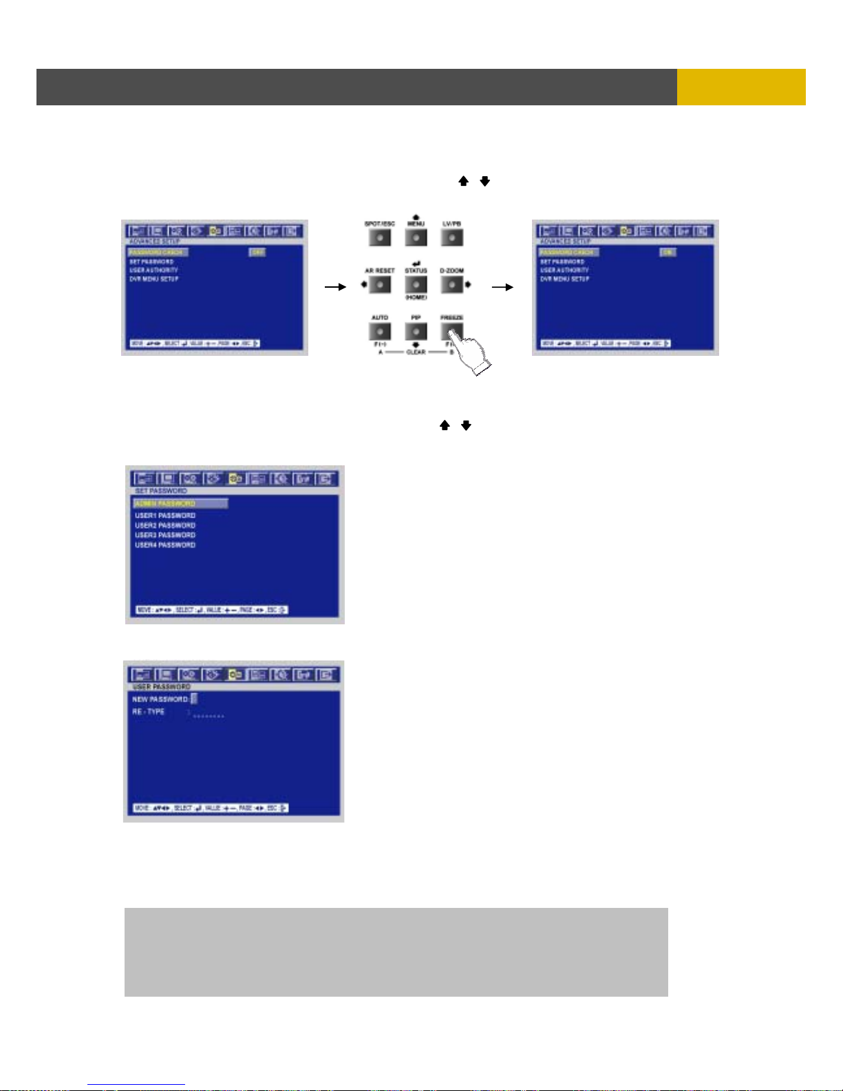
DIGITAL VIDEO RECORDER
69
M
ENU SETUP
6.5.7.1 PASSWORD CHECK
At the ADVANCED SETUP menu,
① Move the cursor to the PASSWORD CHECK using the , buttons.
② Select ON or OFF using the (-), (+) buttons. If you select OFF, password menu won’t work.
6.5.7.2 SET PASSWORD
At the ADVANCED SETUP menu,
① Move the cursor to the SET PASSWORD using the , buttons.
② Press the ENTER button when the cursor is on the SET PASSWORD and the following screen
appears.
③ Select the administrator or user1~4 to change the password and then press “ENTER” button and
you can see the following screen.
④ Insert your desired password in the eight digits marked _ _ _ _ _ _ _ _ beside NEW PASSWORD
using the CAMERA/ NUMBER INPUT buttons.
⑤ And then reinsert 8 numbers of the NEW PASSWORD in the eight digits marked _ _ _ _ _ _ _ _
beside RE-TYPE using the CAMERA/ NUMBER INPUT buttons to verify the password.
⑥ To exit this menu, press the ESC button.
NOTE: You can use only 0~9 number buttons to setup the PASSWORD.
The d efau l t of ADM I N is 11111111, U S ER1 i s 2222 2 222, USER2 is 33333333,
USER3 is 44444444, USRE4 is 55555555.
If you forget the admin password, please contact the authorized dealer.
CAUTION: Change the password after purchasing for a security.
Page 70
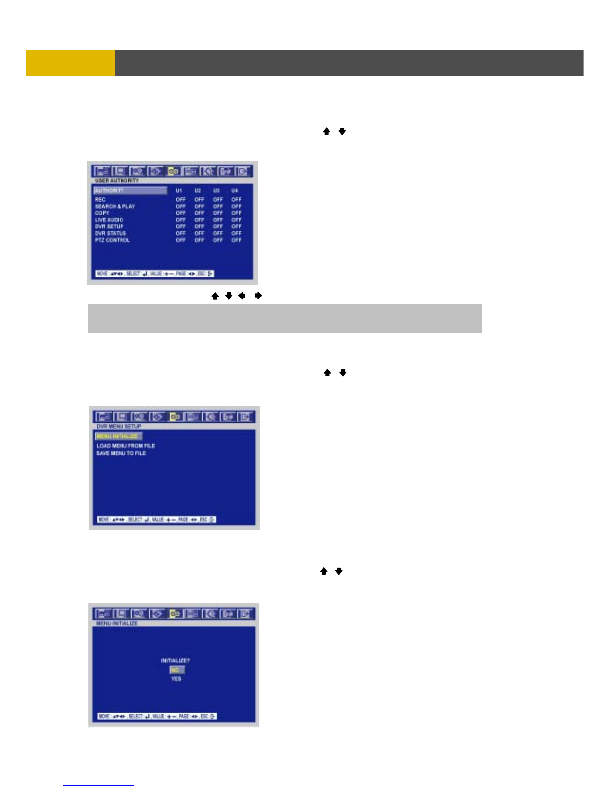
USER’S MANUAL
70
MENU SETUP
6.5.7.3 USER AUTHORITY
At the ADVANCED SETUP menu,
① Move the cursor to the USER AUTHORITY using the , buttons.
② Press the ENTER button when the cursor is on the USER AUTHORITY and the following screen
appears.
③ Move the cursor using the , , , buttons and change the value using the (-), (+) buttons.
6.5.7.4 DVR MENU SETUP
At the ADVANCED SETUP menu,
① Move the cursor to the DVR MENU SETUP using the , buttons.
② Press the ENTER button when the cursor is on the DVR MENU SETUP and the following screen
appears.
6.5.7.4.1 MENU INITIALIZE
At the DVR MENU SETUP menu,
① Move the cursor to the MENU INITIALIZE using the , buttons.
② Press the ENTER button when the cursor is on the DVR INITIALIZE and the following screen
appears.
If you set any items by “ON”, the password will be required when you start to work them.
The defaults are “OFF”.
Page 71
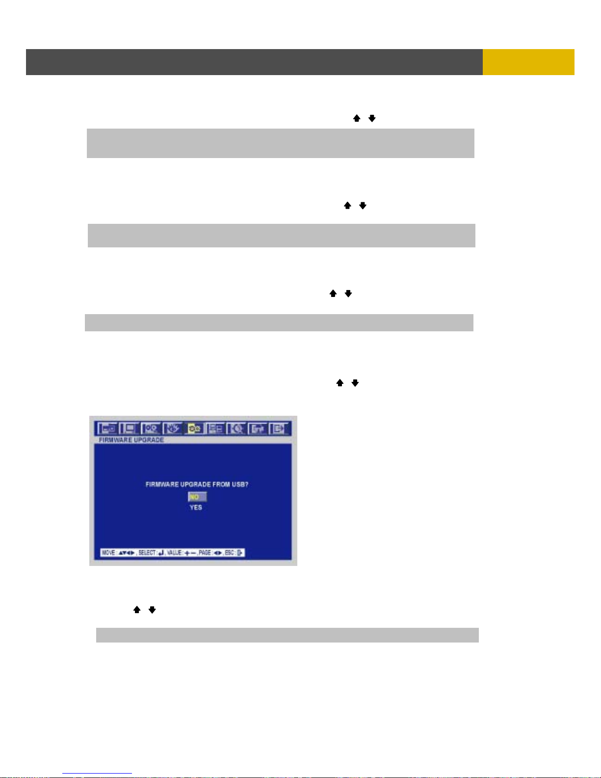
DIGITAL VIDEO RECORDER
71
M
ENU SETUP
③ If you want to initialize, move the cursor to “YES” and then press the ENTER button. If not, move
the cursor to “NO” and then press the ENTER button. Use the , buttons to move the cursor.
6.5.7.4.2 LOAD MENU FROM FILE
At the DVR MENU SETUP menu,
① Insert the USB memory stick to download the menu file from the USB memory stick.
② Move the cursor to the LOAD MENU FROM FILE using the , buttons and then press the
ENTER button.
6.5.7.4.3 SAVE MENU TO FILE
At the DVR MENU SETUP menu,
① Insert the USB memory stick to copy the current DVR menu file to the USB memory stick.
② Move the cursor to the SAVE MENU TO FILE using the , buttons and then press the
ENTER button.
6.5.8 FIRMWARE UPGRADE
At the SYSTEM menu,
① Move the cursor to the FIRMWARE UPGRADE using the , buttons.
② Press the ENTER button when the cursor is on the FIRMWARE UPGRADE and the following
screen appears.
③ If you want to update firmware using the USB port, move the cursor to “YES” and then press the
ENTER button. If not, move the cursor to “NO” and then press the ENTER button.
Use the , buttons to move the cursor.
④ To exit this FIRMWARE UPGRADE screen, press the ESC button.
NOTE : It is possible to copy and upload the menu setting only with a front USB port.
NOTE : It is possible to upgrade the firmware only with a Front USB port.
NOTE: If you do this MENU INITIALIZE, all menu setting values will be factory default.
HDD’s data will not be deleted.
NOTE: This function is to upload the menu file to be saved in USB memory stick in the DVR.
Page 72
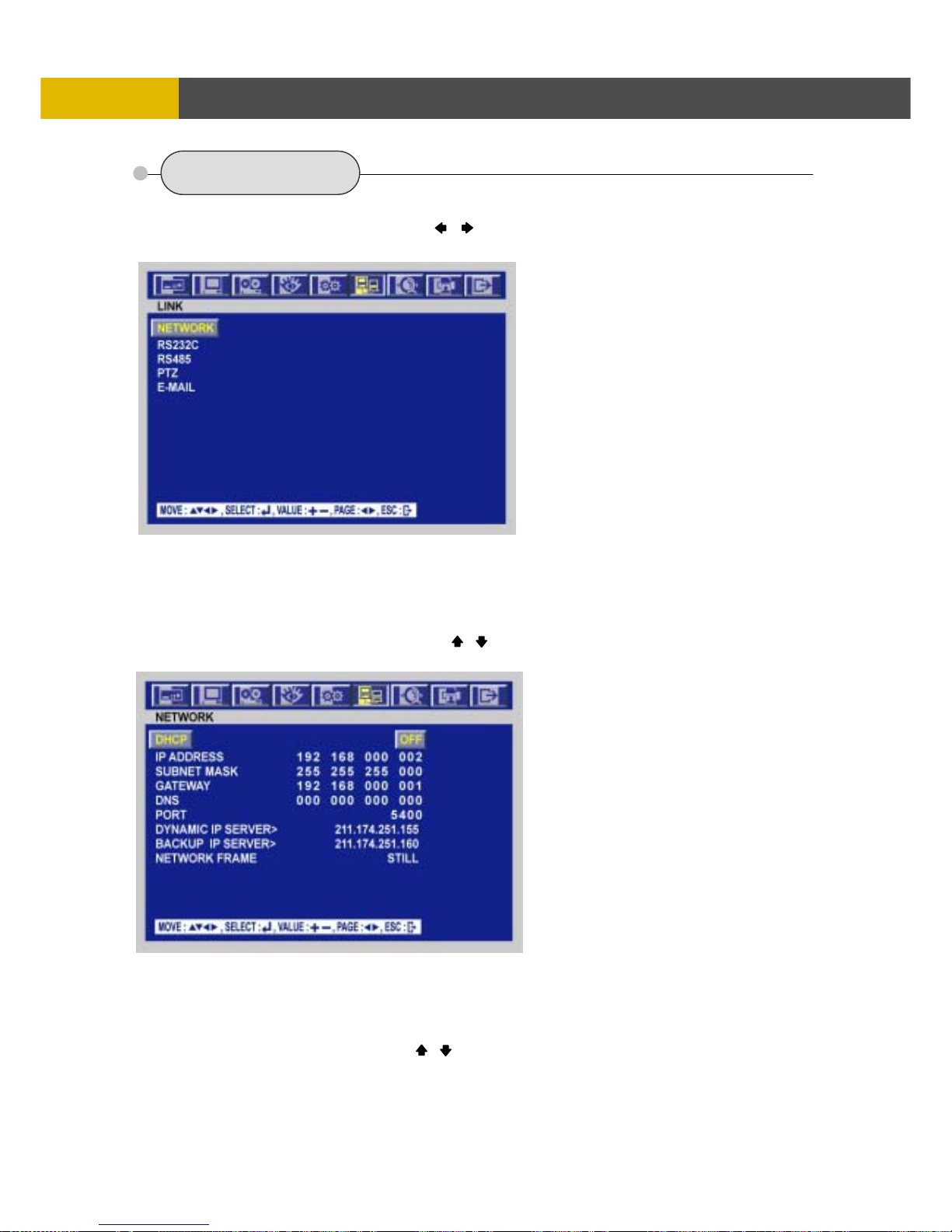
USER’S MANUAL
72
MENU SETUP
6.6 LINK
To set up the LINK menu,
① Move the cursor to the LINK icon using the , in the MENU screen.
② Press the ENTER button when the cursor is on the LINK icon and the following items appear.
6.6.1 NETWORK
At the LINK menu,
① Move the cursor to the NETWORK using the , buttons.
② Press the ENTER button when the cursor is on the NETWORK and the following screen appears.
③ To exit this NETWORK menu, press the ESC button.
<Fixed IP>
6.6.1.1 DHCP
At the NETWORK menu,
① Move the cursor to the DHCP using the , buttons.
② Select “OFF” using the (-), (+) buttons.
Page 73

DIGITAL VIDEO RECORDER
73
M
ENU SETUP
6.6.1.2 IP ADDRESS
At the NETWORK menu,
① Move the cursor to the IP ADDRESS using the , buttons.
② Select the desired position using the
, buttons and set the data value using the (-), (+)
buttons.
6.6.1.3 SUBNET MASK
At the NETWORK menu,
① Move the cursor to the SUBNET MASK using the , buttons. Select the desired position ②
using the
, buttons and set the data value using the (-), (+) buttons.
6.6.1.4 GATEWAY
At the NETWORK menu,
① Move the cursor to the GATEWAY using the , buttons.
② Select the desired position using the
, buttons and set the data value using the (-), (+)
buttons.
6.6.1.5 DNS
At the NETWORK menu,
① Move the cursor to the DNS using the , buttons.
② Select the desired position using the
, buttons and set the data value using the (-), (+)
buttons.
6.6.1.6 PORT
At the NETWORK menu,
① Move the cursor to the PORT using the , buttons.
② Select the desired position using the
, buttons and set the data value using the (-), (+)
buttons.
6.6.1.7 DYNAMIC IP SERVER
At the NETWORK menu,
① Move the cursor to the DHCP using the , buttons.
② Select “ON” using the (-), (+) buttons.
③ Move the cursor to the DYNAMIC IP SERVER using the , buttons.
④ Input the dynamic server IP using the (-), (+) buttons to change the value and
the , buttons to move the cursor.
6.6.1.8 BACKUP IP SERVER
At the NETWORK menu,
① Move the cursor to the DHCP using the , buttons.
② Select “ON” using the (-), (+) buttons.
③ Move the cursor to the BACKUP IP SERVER using the , buttons.
④ Input the backup server IP using the (-), (+) buttons to change the value and
the , buttons to move the cursor.
NOTE: Port setting on DVR and client viewer software must be matched.
NOTE: DHCP is a protocol for assigning dynamic IP addresses to devices on a network.
** You have to connect with Router in case of using a network of PPPOE type because this unit
doesn’t have a PPPOE protocol.
NOTE: DHCP is a protocol for assigning dynamic IP addresses to devices on a network.
** You have to connect with Router in case of using a network of PPPOE type because this unit
doesn’t have a PPPOE protocol.
Page 74
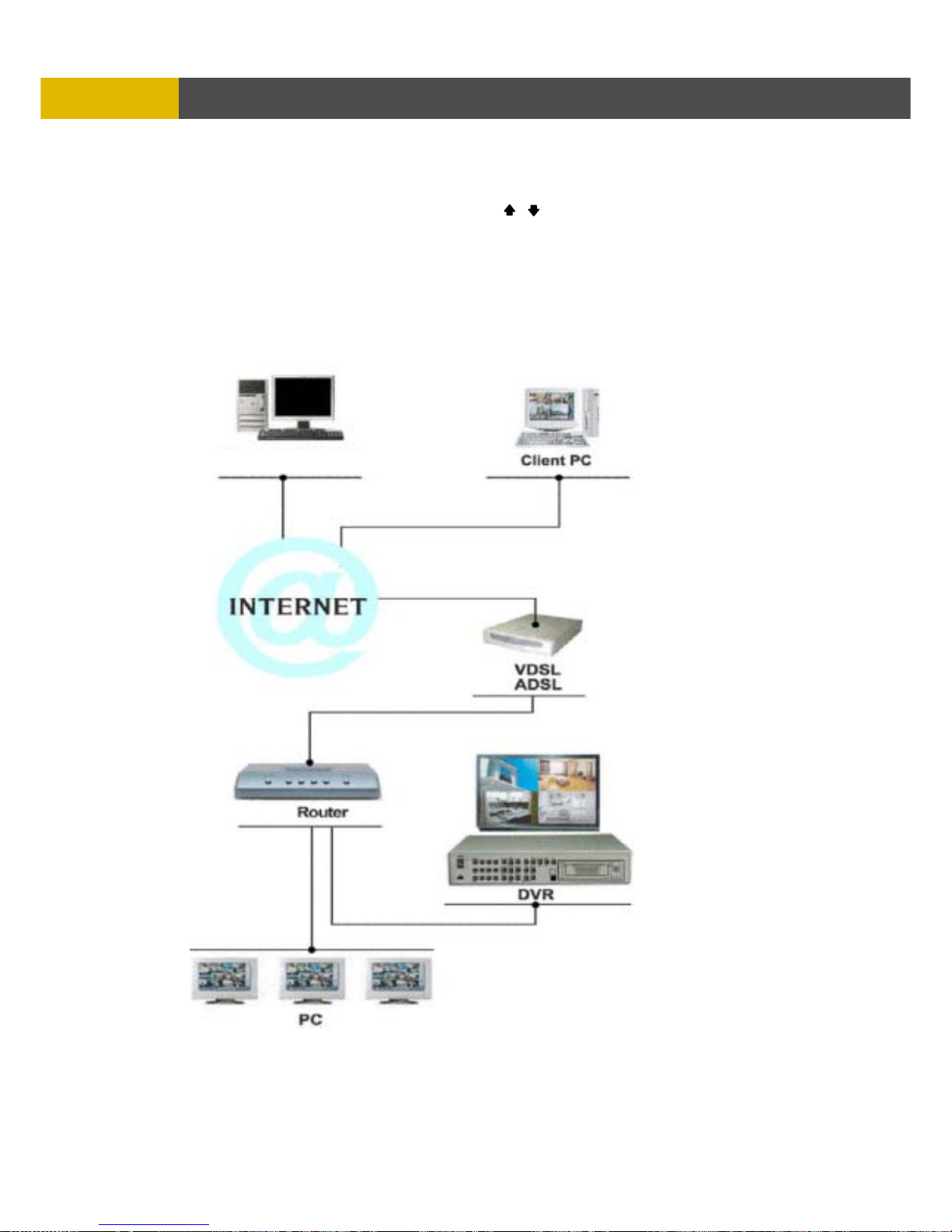
USER’S MANUAL
74
MENU SETUP
6.6.1.9 NETWORK FRAME
At the NETWORK menu,
① Move the cursor to the NETWORK FRAME using the , buttons.
② Select the value using the (-), (+) buttons.
STILL: Transmits only I-Picture of GOP(Group of Picture) to be saved in DVR.
MOTION: Transmits all images of GOP.
** Please refer to the below image in case of a PPPOE type
DDNS
Page 75
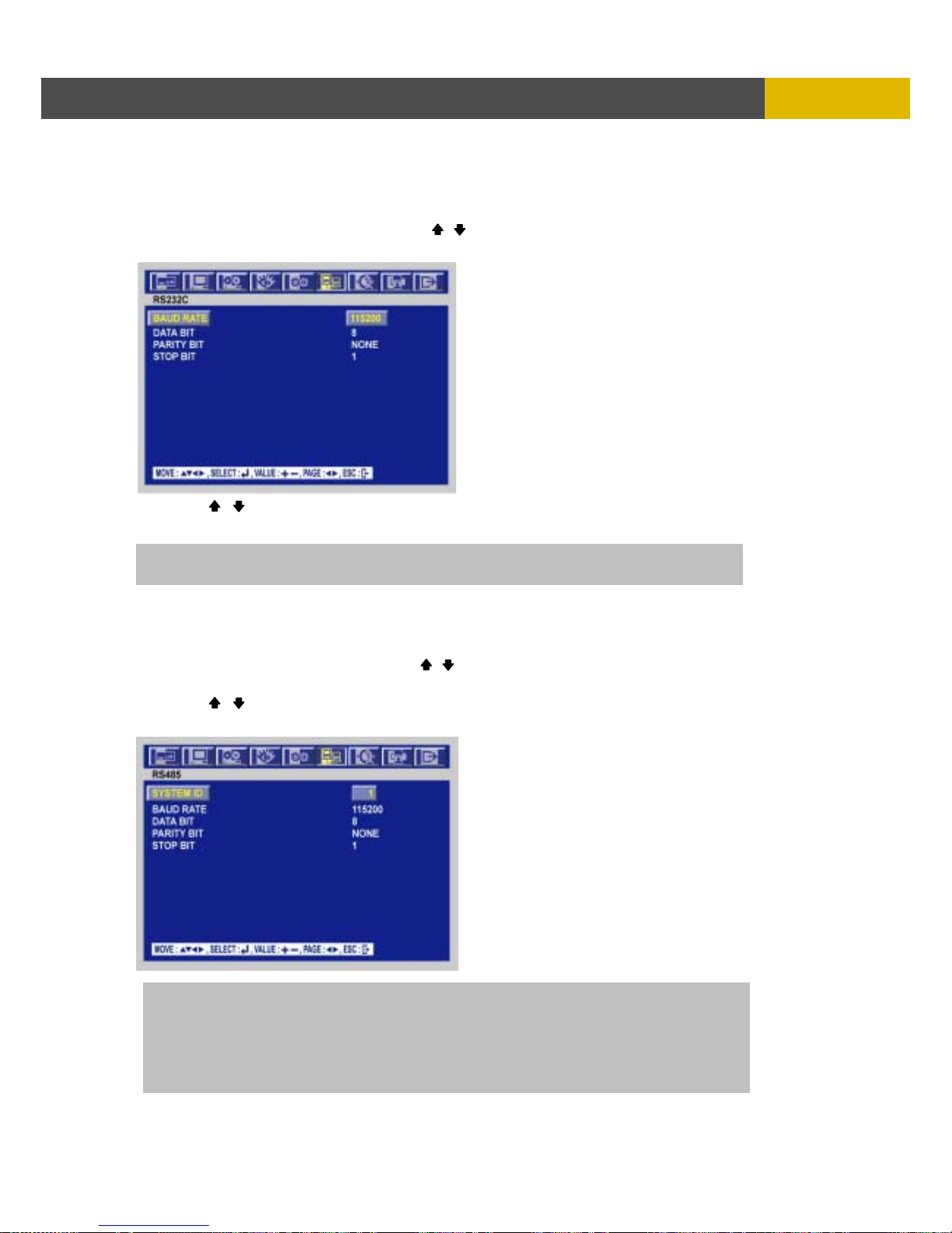
DIGITAL VIDEO RECORDER
75
M
ENU SETUP
6.6.2 RS232C
At the LINK menu,
① Move the cursor to the RS232C using the , buttons.
② Press the ENTER button when the cursor is on the RS232C and the following screen appears.
③ Use the , buttons to choose the item and use the (-), (+) buttons to set the data value.
④ To exit this RS232C menu, press the ESC button.
6.6.3 RS485
At the LINK menu,
① Move the cursor to the RS485 using the , buttons.
② Press the ENTER button when the cursor is on the RS485 and the following screen appears.
③ Use the , buttons to choose the item and use the (-), (+) buttons to set the data value.
④ To exit this RS485 menu, press the ESC button.
NOTE
SYSTEM ID : Unit distinction address at Remote keyboard.
BAUD RATE : Data transmission speed per second.
DATA BIT : Data transmission bit.
PARITY BIT : Data transmission error checking.
STOP BIT : Data transmission ending bit
NOTE: The Set of value bring about is SERIAL port at DVR near side.
Page 76
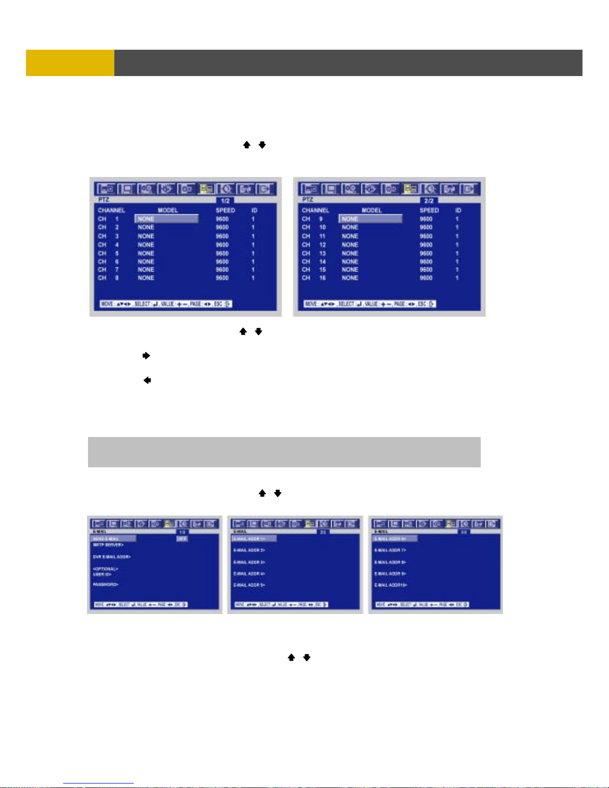
USER’S MANUAL
76
MENU SETUP
6.6.4 PTZ
At the LINK menu,
① Move the cursor to the PTZ using , buttons.
② Press the ENTER button when the cursor is on the PTZ and the following 1 or 2 pages screen
appears.
③ Select the desired channel using , buttons.
④ Use the (-), (+) buttons to select the right model of installed PTZ camera.
⑤ Press the button to set up a ID of the PTZ camera.
⑥ Use the (-), (+) buttons to select the desired ID.
⑦ Press the button to see the next page.
⑧
To exit this PTZ menu, press the ESC button.
6.6.5 E-MAIL
At the LINK menu,
① Move the cursor to the E-MAIL using , buttons.
② Press the ENTER button when the cursor is on the E-MAIL and the following screen appears.
6.6.5.1 SEND E-MAIL
At the E-MAIL menu,
Move the cursor to the SEND E-MAIL using the , buttons and select “ON” using the (-), (+)
buttons to send e-mails when an event happened.
NOTE: If you want to use this function, you have to input DNS address.
Please refer to 6.6.1.
Page 77
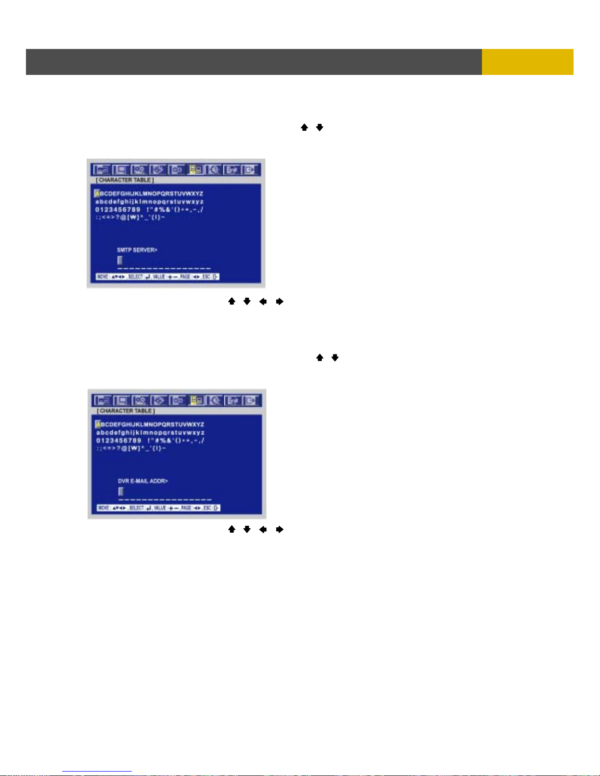
DIGITAL VIDEO RECORDER
77
M
ENU SETUP
6.6.5.2 SMTP SERVER
At the E-MAIL menu,
① Move the cursor to the SMTP SERVER using the , buttons to input the e-mail sever address
to be used by DVR.
② Press the ENTER button and the following screen appears.
③ Select the character using the , , , buttons and then press the ENTER button.
④ To exit this CHARACTER TABLE screen, press the ESC button.
6.6.5.3 DVR E-MAIL ADDR
At the E-MAIL menu,
① Move the cursor to the DVR E-MAIL ADDR using the , buttons to input the e-mail address to
receive the e-mail when an event happened.
② Press the ENTER button and the following screen appears.
③ Select the character using the , , , buttons and then press the ENTER button.
④ To exit this CHARACTER TABLE screen, press the ESC button.
Page 78
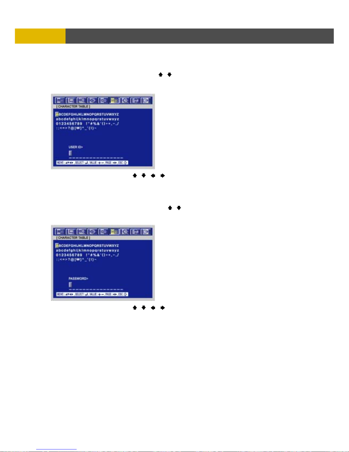
USER’S MANUAL
78
MENU SETUP
6.6.5.4 USER ID
At the E-MAIL menu,
① Move the cursor to the USER ID using the , buttons to input the e-mail account to be used
by DVR.
② Press the ENTER button and the following screen appears.
③ Select the character using the , , , buttons and then press the ENTER button.
④ To exit this CHARACTER TABLE screen, press the ESC button.
6.6.5.5 PASSWORD
At the E-MAIL menu,
① Move the cursor to the PASSWORD using the , buttons to input the account password to be
used by DVR.
② Press the ENTER button and the following screen appears.
③ Select the character using the , , , buttons and then press the ENTER button.
④ To exit this CHARACTER TABLE screen, press the ESC button.
Page 79
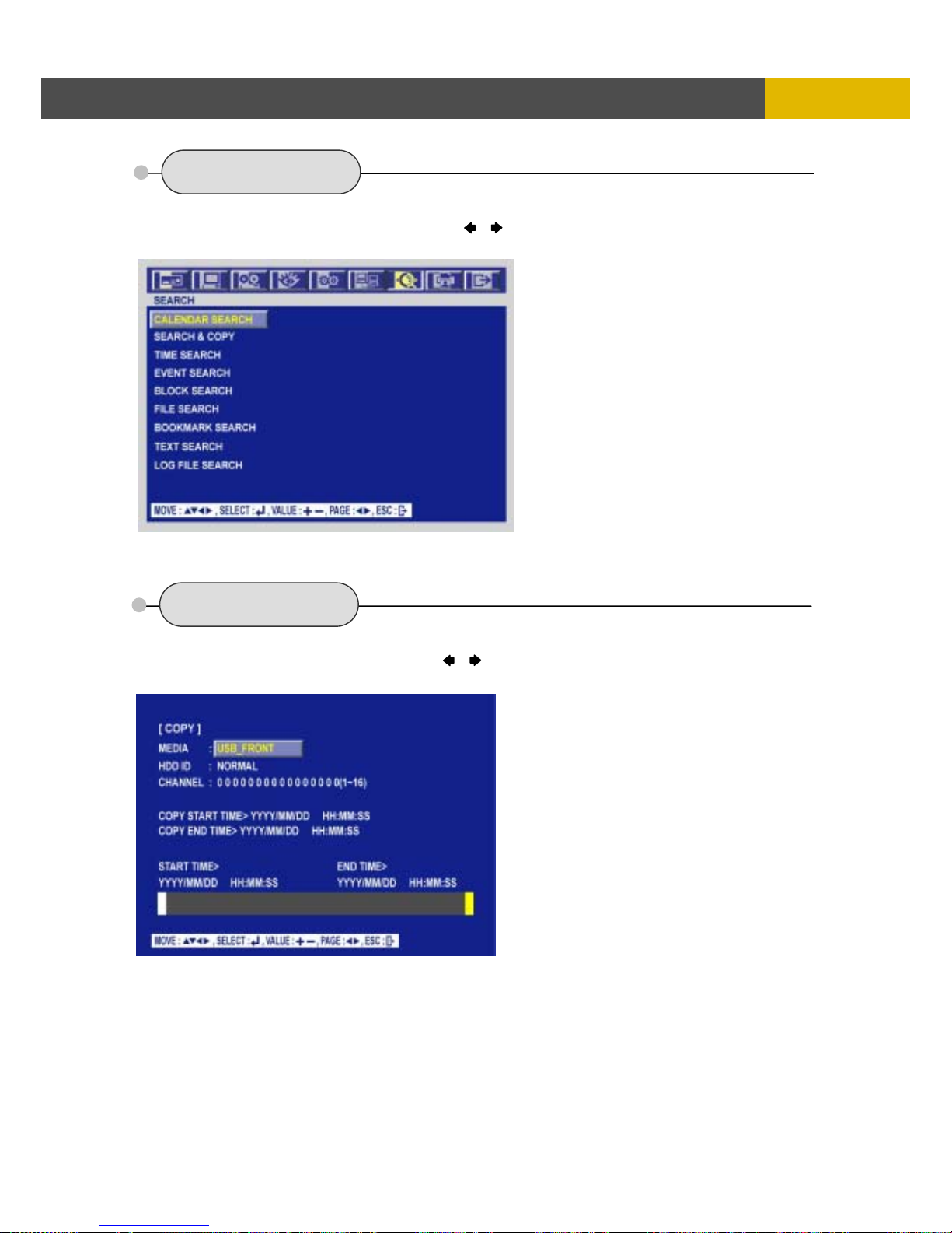
DIGITAL VIDEO RECORDER
79
M
ENU SETUP
6.7 SEARCH
To set up the SEARCH menu,
① Move the cursor to the SEARCH icon using the , in the MENU screen.
② Press the ENTER button when the cursor is on the SEARCH icon and the following items appear.
** Please, refer to Search & Playback of Chapter 5 Operation.
6.8 COPY
To set up the COPY menu,
① Move the cursor to the COPY icon using the , in the MENU screen.
② Press the ENTER button when the cursor is on the COPY icon and the following items appear.
** Please, refer to Copy of Chapter 5 Operation.
Page 80
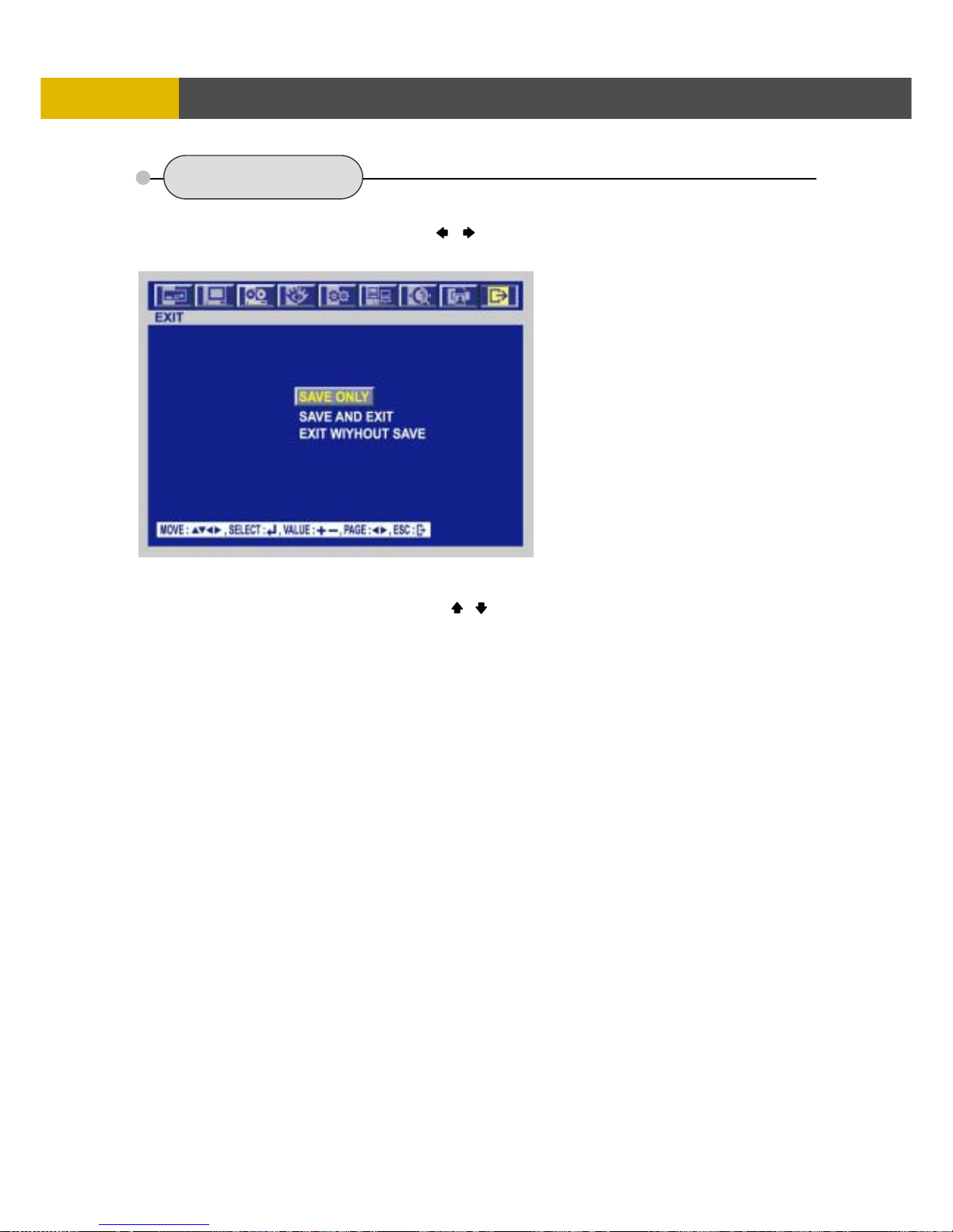
USER’S MANUAL
80
MENU SETUP
6.9 EXIT
At the MENU screen,
① Move the cursor to the EXIT icon using the , buttons.
② Press the ENTER button when the cursor is on the EXIT icon and the following items appear.
③ Move the cursor to the desired item using the , buttons and press the ENTER button.
- SAVE ONLY : Select this item if you want only to save the changed setup.
- SAVE AND EXIT : Select this item if you want to save the changed setup and exit this screen.
- EXIT WITHOUT SAVE : Select this item if you want not to save the changed setup before
exiting this screen
Page 81
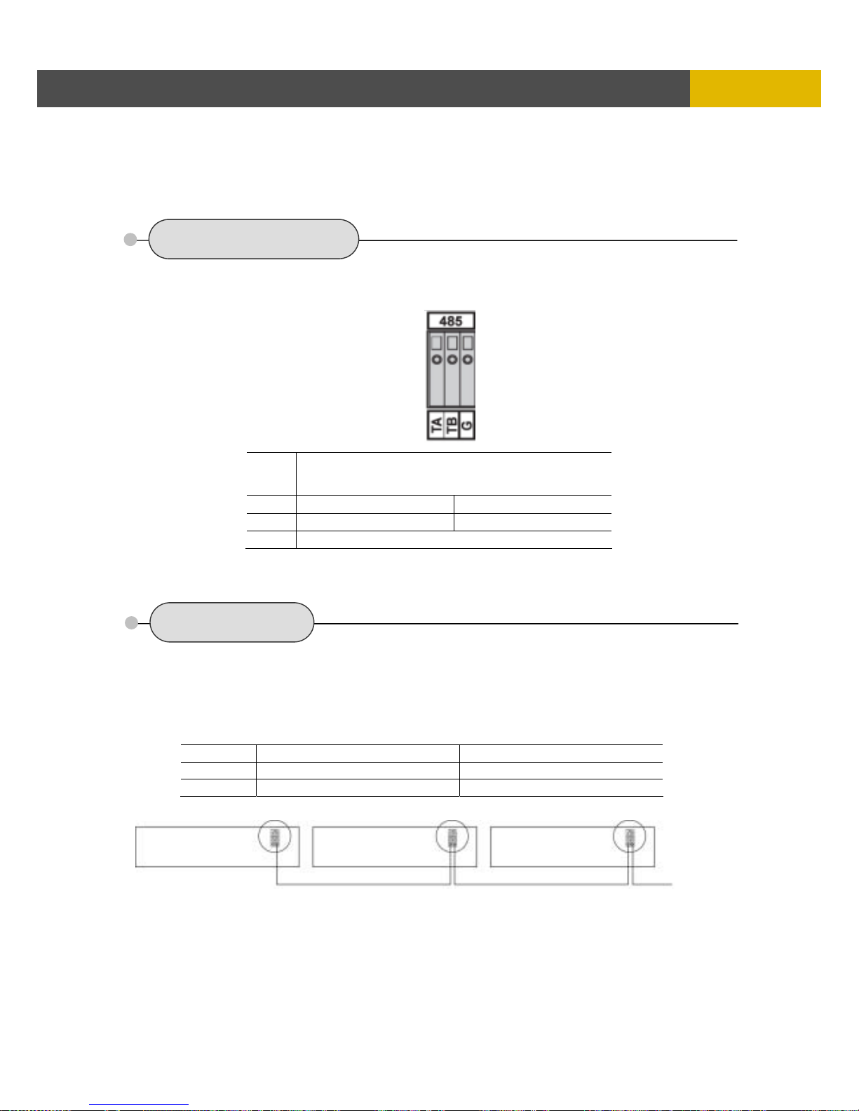
DIGITAL VIDEO RECORDER
81
EXTERNAL TERMINAL INFORMATIO
N
Chapter 7
External Terminal Information
7.1 RS-485
These ports are to control the connected PTZ cameras and can be used to connect the external
controller.
7.2 T.ADJ
Time adjust input port is high level at normal and check a signal every 100ms.
Time adjust output port is open at normal and a space cling to change
a minute at GND.
During keep up 250ms
No DESCRIPTION
1 TA(TX+) RS485:Transmit data
2 TB(TX-) RS485: Receive data
3 GND
NO DESCRIPTION FALLING EDGE
1 TIME REFERENCE INPUT TTL
2 TIME REFERENCE OUTPUT
To other T.ADJ Input
Page 82
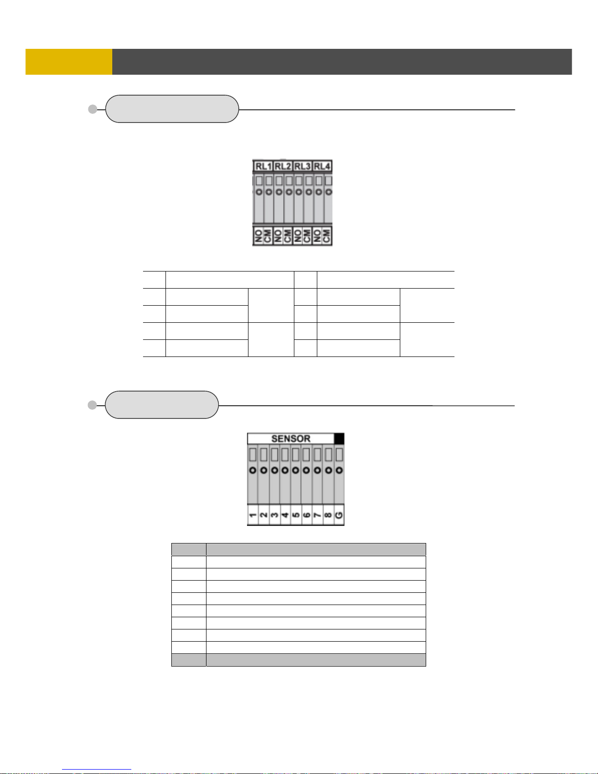
USER’S MANUAL
82
EXTERNAL TERMINAL INFORMATION
7.3 RELAY OUT
For controlling alarm output by relay
7.4 ALARM
NO DESCRIPTION NO DESCRIPTION
1 NO(Normal Open) 5 NO(Normal Open)
2 CM(Common)
ALARM
6 CM(Common)
MD
3 NO(Normal Open) 7 NO(Normal Open)
4 CM(Common)
V-LOSS
8 CM(Common)
POWER
USER
NOT USED
HDD ERROR
No DESCRIPTION
1 EXTERNAL ALARM 1 INPUT
2 EXTERNAL ALARM 2 INPUT
3 EXTERNAL ALARM 3 INPUT
4 EXTERNAL ALARM 4 INPUT
5 EXTERNAL ALARM 5 INPUT
6 EXTERNAL ALARM 6 INPUT
7 EXTERNAL ALARM 7 INPUT
8 EXTERNAL ALARM 8 INPUT
G ALARM IN COMMON GND
Page 83
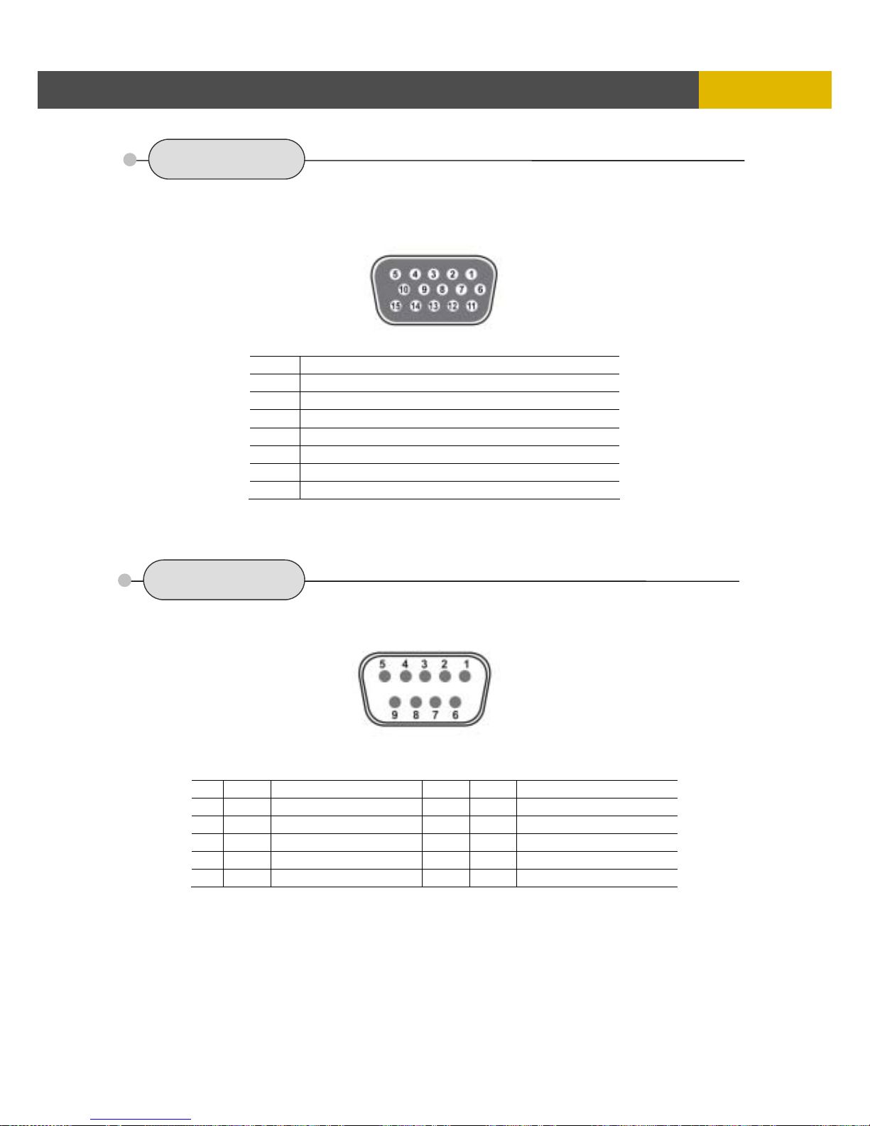
DIGITAL VIDEO RECORDER
83
EXTERNAL TERMINAL INFORMATIO
N
7.5 VGA
This DVR supports 1024 x 768 resolution & 70Hz refreshed rate in NTSC/PAL mode.
7.6 SERIAL
No DESCRIPTION
1 RED(Red Video [75ohm, 0.7Vp-p] )
2 GREEN(Green Video [75ohm, 0.7Vp-p] )
3 BLUE(Blue Video [75ohm, 0.7Vp-p] )
4~12 Reserved
13 HSYNC or CSYNC(Horizontal or Composite Sync.)
14 VSYNC(Vertical Sync.)
15 Reserved
No Description No Description
1 DCD Not used 6 DSR Not used
2 RxD Receive data 7 RTS Not used
3 TxD Transmit data 8 CTS Not used
4 DTR +12V output 9 RI Not used
5 GND Signal Ground
VGA
SERIAL
Page 84
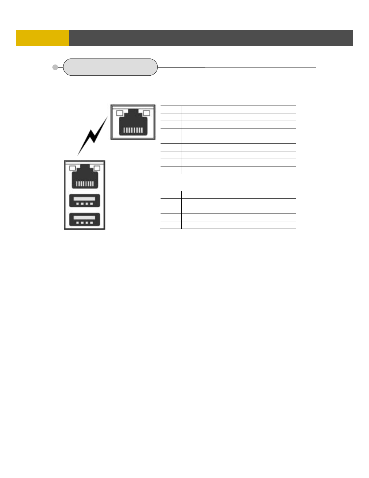
USER’S MANUAL
84
EXTERNAL TERMINAL INFORMATION
7.7 Ethernet / USB
For both 10Base-T and 100 Base-TX.
No DESCRIPTION
1 N/C (Not Connected)
2 N/C (Not Connected)
3 RX-(Receive Data-)
4 N/C (Not Connected)
5 N/C (Not Connected)
6 RX+(Receive Data+)
7 TX-(Transmit Data-)
8 TX+(Transmit Data+)
No DESCRIPTION
1 VCC
2 USB DATA -
3 USB DATA +
4 GND
ETHERNET
USB2
USB1
Page 85
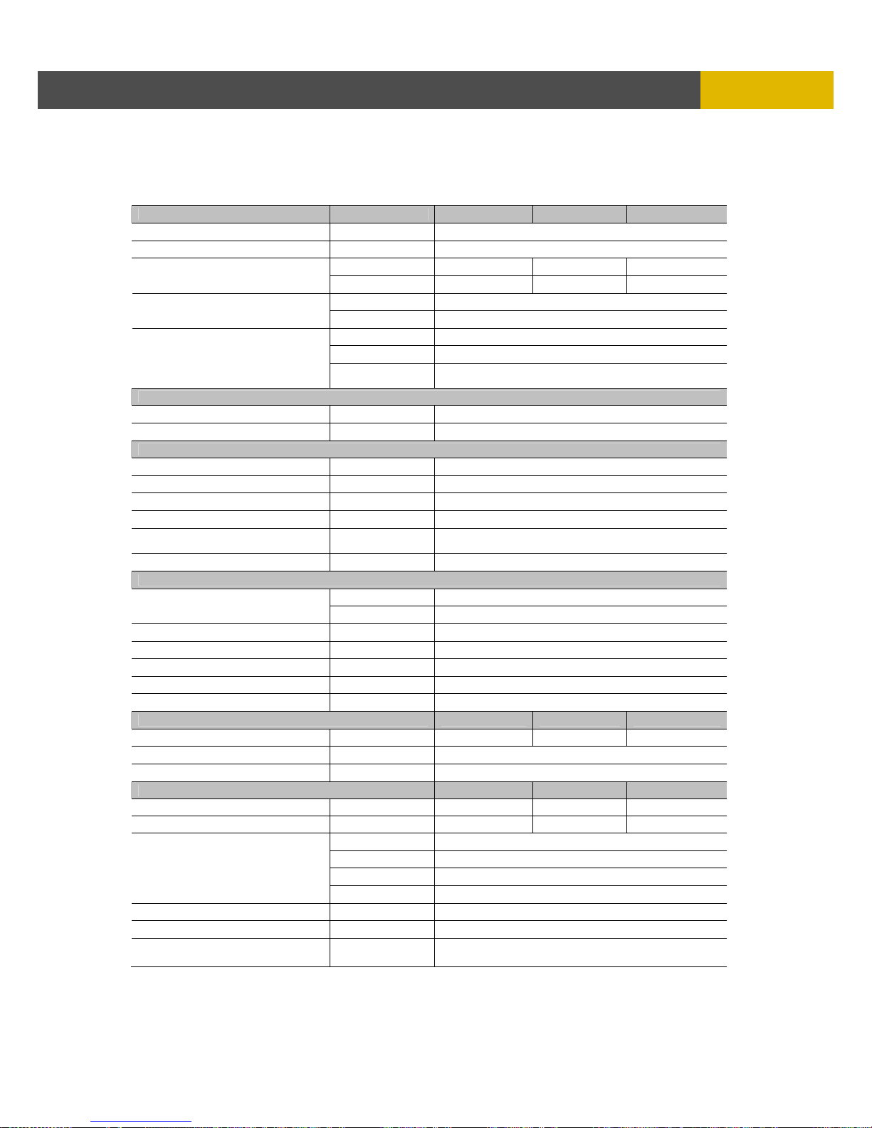
DIGITAL VIDEO RECORDER
85
SPECIFICATION
S
Chapter 8
Specifications
1. VIDEO ANX-470 ANX-870 ANX-1670
Input Level
1.0 Vp-p±10% Composite, 75Ω Balanced
Video Standard NTSC(525 lines)/ PAL(625 lines)/ AUTO
NTSC 120fps 240fps 480fps
Display Speed
PAL 100fps 200fps 400fps
NTSC 720(H) X 480(V)
Display Resolution
PAL 720(H) X 576(V)
Main
1.0Vp-p Composite, 75Ω Balanced (YC Output)
Spot
1.0Vp-p Composite, 75Ω Balanced
Monitor Output
VGA
Analogue non-interlaced RGB.
This DVR is compatible with
TFT LCD monitor that support 50Hz VGA mode in PAL
2. AUDIO
LINE Input Level
0.5~1.4Vp-p@20kΩ
Output Level
-10dB 1KΩ
3. RECORDING
*1 Compression Method MPEG4 (Refer to the below table)
*2 Recording speed Refer to the below table
Quality User Define Low/ Fine/ Superfine
Scheduling Available per hour/ each channel
Mode
Manual / Event (Motion detection, Video loss, Sensor)/
Schedule
Water Marking Available
4. HDD
Internal Storage 1 Removable HDD + 2 HDDs (1TB x 3)
Capacity
External Storage 40 HDDs (10 HDDs in an external bay x 4)
Speed Min. 5400RPM, 7200RPM
DMA 45MHz DMA
Type EIDE compatible
Seek time Faster than 9.0ms avg.
External Bay Interface USB 2.0
5. ALARM ANX-470 ANX-870 ANX-1670
Sensor Input Terminal block 4 ports 8 ports 16ports
Alarm Output 4 Relay out (Programmable), Terminal block
Motion Detection Available per each camera/ Multi-detection level
6. CONNECTORS ANX-470 ANX-870 ANX-1670
Video Input BNC 4 ports 8 ports 16ports
Loop Output BNC 4 ports 8 ports 16ports
Main BNC 1 port
Spot BNC 1 port
S-Video BNC 1 port (4 pins mini DIN)
Monitor Output
VGA(Option) BNC 1 port (15 pins female DSUB)
Audio Input Stereo 2 ports: Audio 4 CH (Line only)
Audio Output RCA 1 CH (Line only) : Rear 1 port
USB 2.0
HDD extension/ Mouse/ USB memory stick/ CD-RW/
DVD±RW (Front 1 port, Rear 2 ports)
Page 86
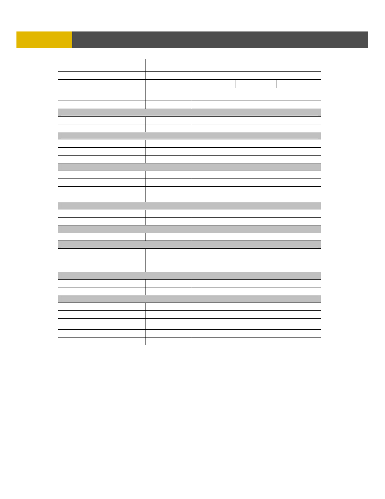
USER’S MANUAL
86
SPECIFICATIONS
Serial
External control (RS-232C) /
For debugging : 9 pins male DSUB
Terminal Block External control (RS-485)
Alarm Input 4CH 8CH 16CH
Alarm Output
4 Relay output : 3 pins terminal block
(Normal-Open, Normal-Close, Common) x 4
Ethernet RJ45 connector, 10/100 Mbps
7. ELECTRICAL
Power Source AC (AC85V-235V) to DC(+12V/6.67A)Adaptor
Power Consumption App. 45W(Including 1 HDD)
8. ENVIRONMENTAL
Operating Temperature
0℃ ~ + 40℃
Storage Temperature
-10℃ ~ + 60℃
Humidity 30 ~ 90%RH (non-condensing)
9. PHYSICAL
Construction Steel case
Color Black
Dimension 420(W) x 68(H) x 330(D) mm
Weight App. 4kg (Including 1 HDD)
10. BACKUP & COPY
Digital Backup Event Backup/ Mirroring
Copy External HDD/ CD-RW/ DVD±RW/ USB Stick (2.0)
11. SEARCHING & PLAYBACK
Searching Method Time/ Event/ File/ Bookmark/POS/ Log file
12. MULTI-REMOTE SURVEILLANCE
Monitoring Environment Client software/ Central monitoring system/ Web
Max. connection DVR 16 DVRs accessible
Max. client Supporting multi-client (16 clients accessible)
13. SYSTEM MONITORING & RECOVERY
Monitoring Software Watchdog
Recovery Auto-Reboot by Watchdog/ Automatic database recovery
14. Others
OS Embedded Linux
Duplexer or Triplexer Triplexer
Control Device
Front key/ Remote controller/ Mouse/ Network viewer
Remote keyboard
File compatibility with PC (Windows) Compatible
Number of event list/ Log file list 20,000/ 20,000
Page 87
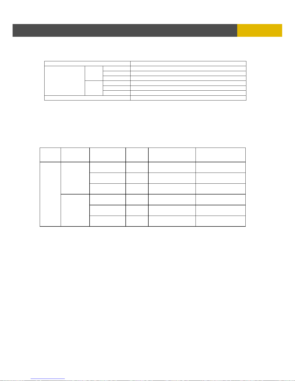
DIGITAL VIDEO RECORDER
87
256 CAMERA INTEGRATION SYSTEM
< Recording Speed Table >
*Note 1, 2 Unit : ips
Model 4CH/ 8CH /16CH
360 x 240 120
720 x 240 60
NTSC
720 x 480 30
360 x 288 100
720 x 288 50
Recording Speed
PAL
720 x 576 25
Compression Method MPEG4
RECORDING CONDITIONS (NTSC)
Based on 120GB and connecting all channels.
This DVR can support up to 45TB with external HDD storage devices.
The following table was calculated by a still image.
RECORDING TIME TABLE
MODEL
RECORD
IMAGE
IMAGE
QUALITY
IMAGE
SIZE
120ips(360x240)
60ips(720x240)
30ips(720x480)
60ips(360x240)
30ips(720x240)
15ips(720x480)
SUPERFINE
2208
Bytes
125 Hours 250 Hours
FINE
1792
Bytes
153 Hours 306 Hours
Color Bar
(Simple
image)
LOW
1288
Bytes
224 Hours 448 Hours
SUPERFINE
8680
Bytes
34 Hours 68 Hours
FINE
5640
Bytes
50 Hours 100 Hours
Mid-
class
DVR
Cross
Hatch
(Complex
image)
LOW
3696
Bytes
72 Hours 144 Hours
• The figures in the Recording Time Table were estimated under ideal recording conditions and may
vary from your actual recording situation.
• In the Recording Time Table, multiply by 2 for recording hours with an 240 GB HDD and 3 for
recording hours with a 360 GB HDD.
• The complexity of the image and the amount of motion recorded greatly influences the recording
capacity of your hard drive (HDD). The higher the frames per second and the higher the video
quality setting, the lower your HDD recording capacity will be. In the same manner, the lower the
frames per second setting and the lower the video quality setting, the higher your HDD recording
capacity will be.
• Note that the lower frame rate does not mean a lower video quality. The image quality remains the
same whether the frames per second setting is set high or low. One frame per second is the same
as taking a photo every second.
• There are several factors that influence the recording capacity of your hard drive.
(a) The number of cameras used
(b) The complexity of recording image
(c) The number of frame recorded per second
(d) The image quality setting – Superfine, Fine or Low
Page 88
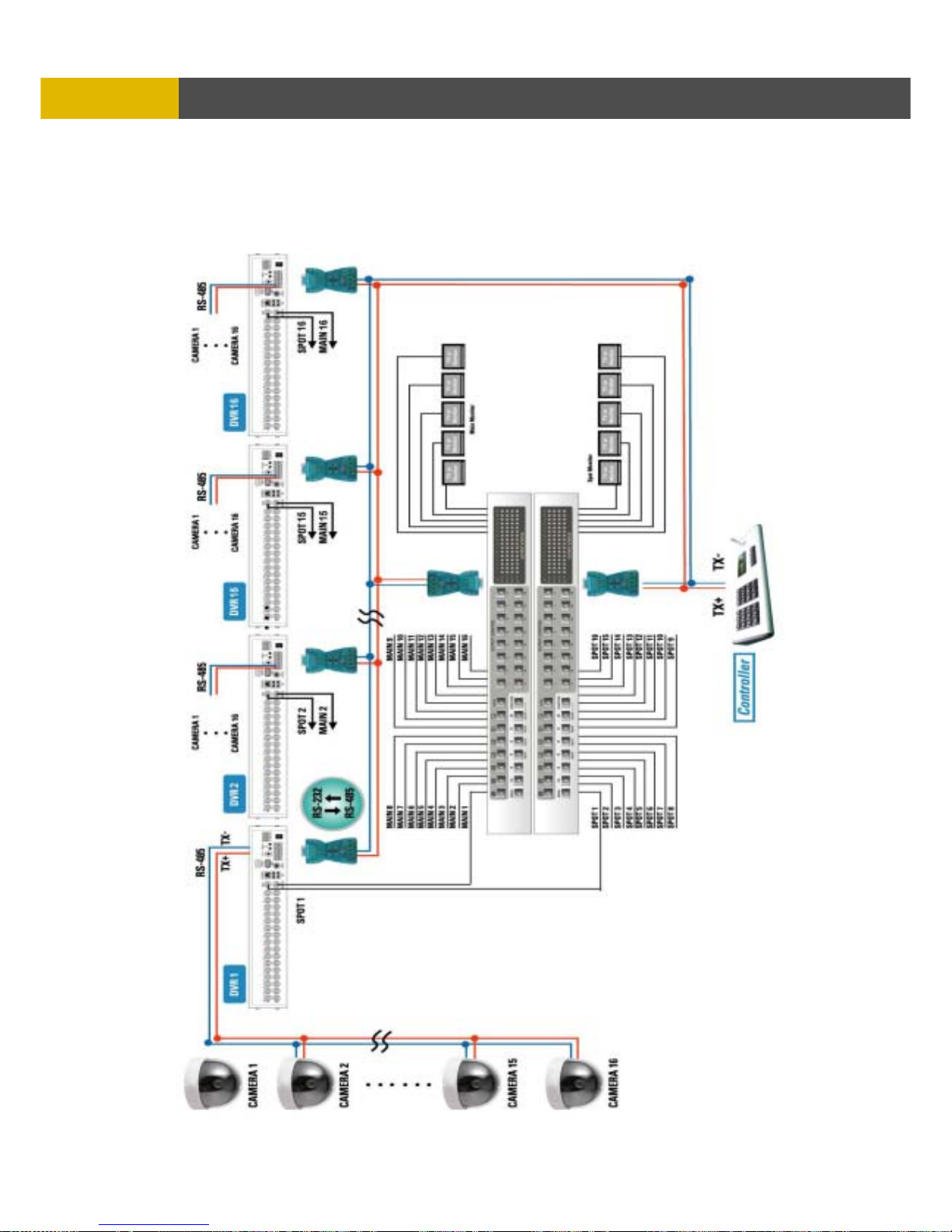
USER’S MANUAL
88
SPECIFICATIONS
Chapter 9
256 Camera Integration system
Block Diagram
Page 89
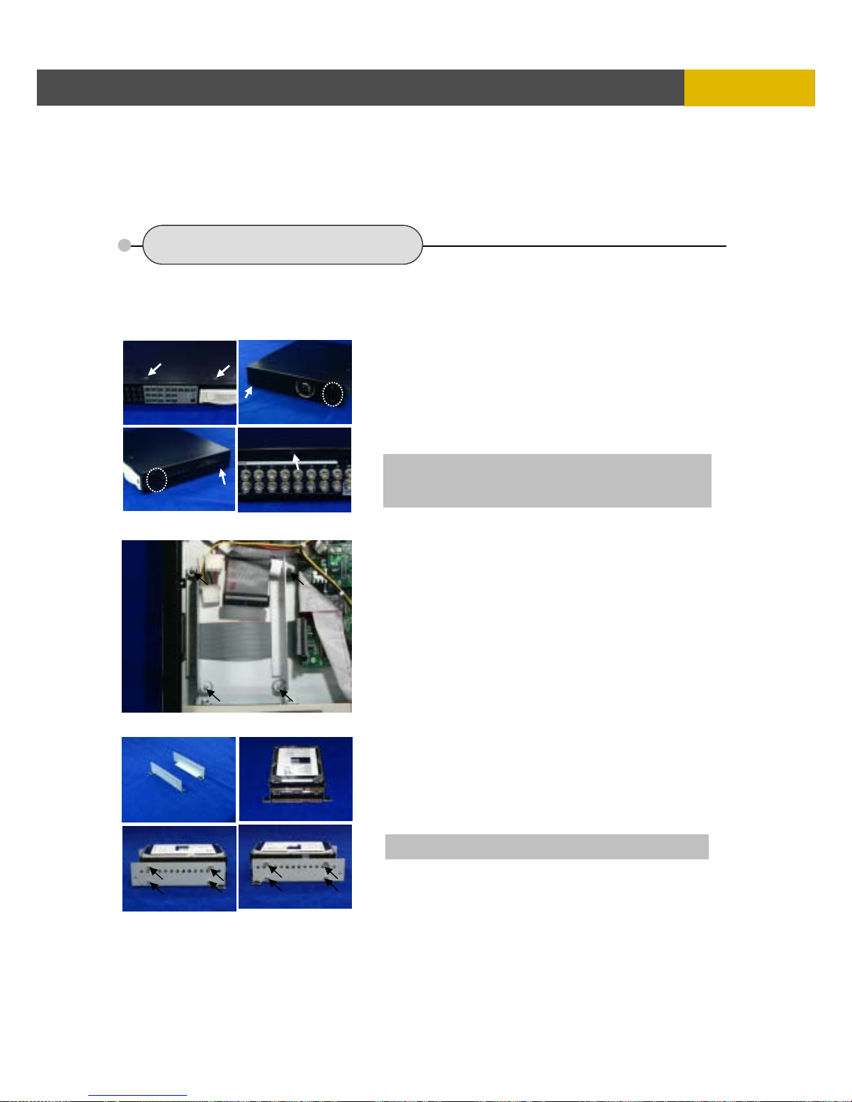
-
DIGITAL VIDEO RECORDER
89
HDD INSTALLATION PROCESS
Chapter 10
HDD Installation Process
10.1 Internal HDD installation
10.1.1 How to install the internal Hard Disk Drive(s).
1) Unscrew on the top, the side and the rear of this
unit as indicated to remove the cover.
2) Remove the upper cover from the unit and unscrew
to remove the rack mounts as indicated.
3) Fix the additional HDD to rack mount with
the screws as indicated.
Caution) Plug out the power cord before addition / removal /
change of HDD
* All HDDs must be set by slave or master
Page 90
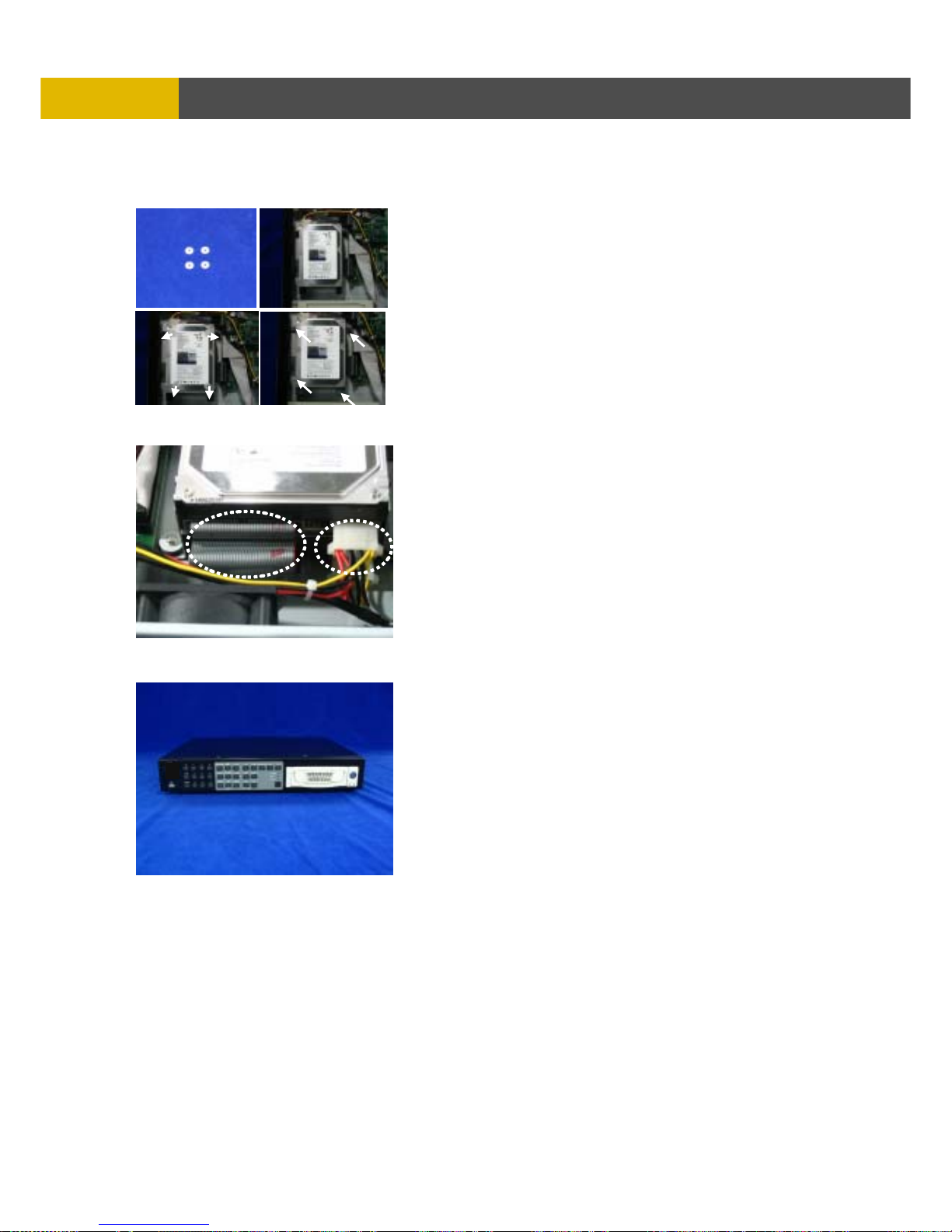
USER’S MANUAL
90
HDD INSTALLATION PROCESS
4) Place the HDD(s) on the HDD plate and screw as
indicated. Put the ring guides same as picture on
the rubber before screwing.
(Set the master or slave of HDD before fixing
the HDD(s) into DVR.
Refer to the HDD Jumper Setting Information.)
5) Connect the power and the flat cables as indicated.
6) Close the top cover and screw.
Page 91
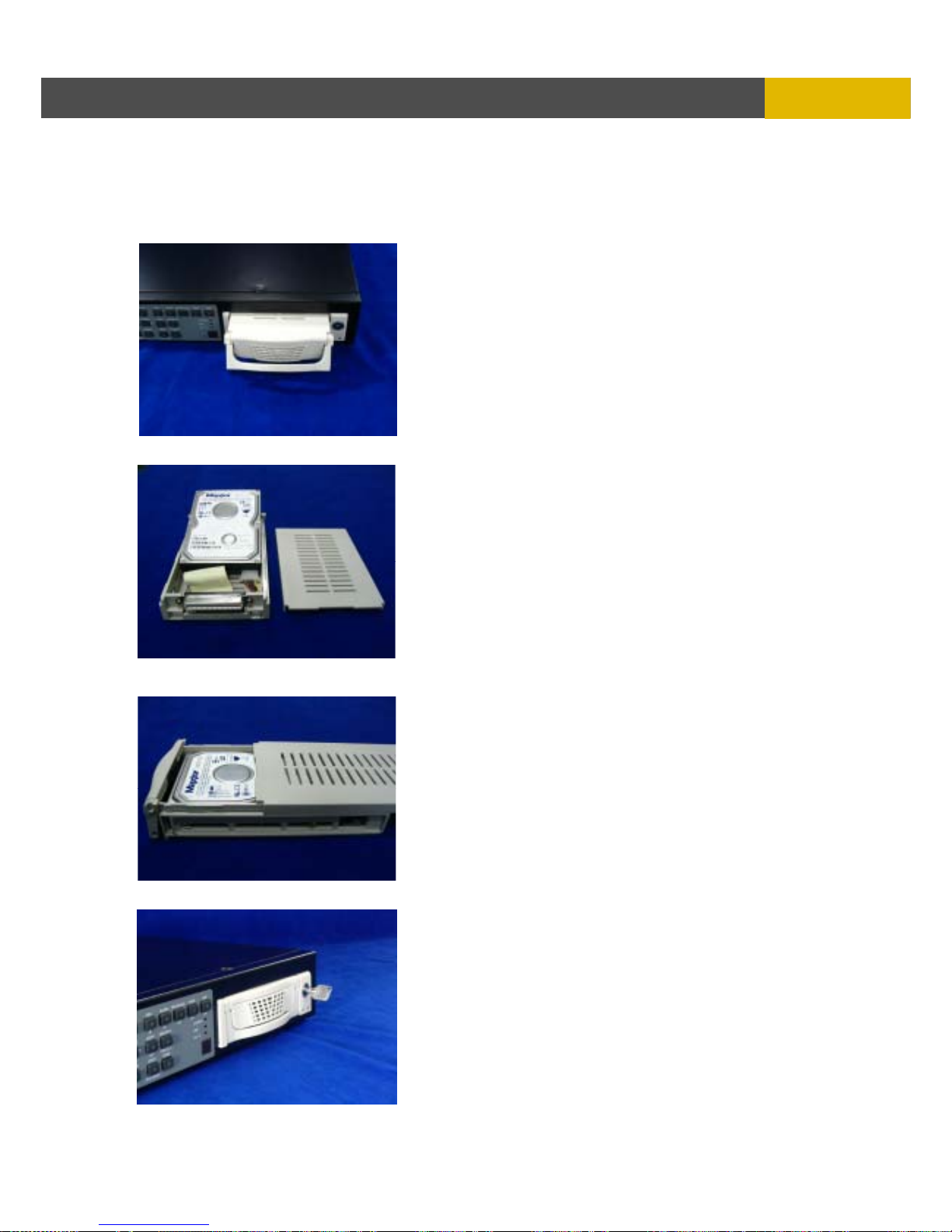
-
DIGITAL VIDEO RECORDER
91
HDD INSTALLATION PROCESS
10.1.2 How to install Hard Disk Drive(s) into the removable HDD rack.
1) Grip the strap of removable HDD rack and
pull it out.
2) Remove the cover of removable HDD rack and
connect the HDD with the cables as indicated.
3) Put the HDD into the rack and close the top cover.
4) Fix the removable HDD rack into the unit and
lock using the supplied key.
Page 92
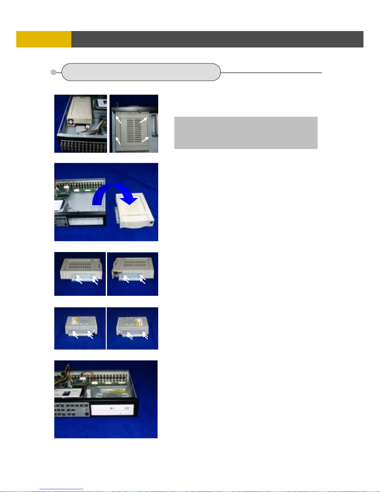
USER’S MANUAL
92
HDD INSTALLATION PROCESS
10.2 DVD±RW(or CD-RW) installation
1) Put out the cables and unscrew to remove
the removable HDD rack as indicated.
NOTE
If you want to install DVD±RW (or CD-RW) into this
DVR, you need a USB to IDE interface board.
Please ask to a seller.
2) Remove the removable HDD rack from DVR set
as the picture.
3) Unscrew to remove the HDD rack mount as
indicated.
4) Screw to fix the rack mount on DVD±RW
(or CD-RW) as indicated.
5) Put the DVD±RW(or CD-RW) into the unit as
indicated.
Page 93
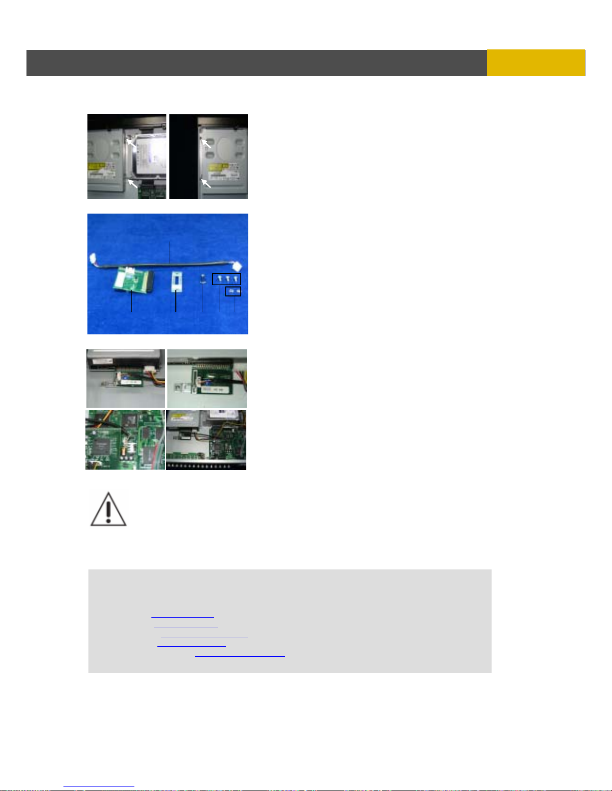
-
DIGITAL VIDEO RECORDER
93
HDD INSTALLATION PROCESS
6) Screw to fix the DVD±RW(or CD-RW) as indicated.
7) Prepare for the USB to IDE interface board and parts
to connect it as the picture.
8) Connect the USB to IDE interface board and cable as
the picture and then close the upper cover of the unit.
HDD Jumper Setting Information
Before install the Hard Disk Drive(s), please read the jumper setting information on
the label. If the jumper is not set properly, the system will be disordered.
Jumper setting is different according to HDD model.
Please visit following web sites of Hard Disk Drive manufacturer for more
information about jumper setting.
HITACHI : www.hitachi.com
MAXTOR : www.maxtor.com
SAMSUNG : www.samsunghdd.com
SEAGATE : www.seagate.com
WESTERN DIGITAL : www.westerndigital.com
○
6
○
5
○1 ○2 ○3○
4
Page 94

USER’S MANUAL
94
NETWORK VIEWER INSTALLATION
Chapter 11
Network Viewer
The DVR Viewer is a dedicated client program that connects to, monitors and manages up to 16
DVRs simultaneously.
11.1 SYSTEM REQUIREMENT
The DVR Viewer receives, decodes and displays data for up to 16 DVRs or up to 256 cameras
simultaneously requiring a powerful personal computer to take full advantage of the program. The
following is the minimum and recommended PC specification.
Minimum Recommended
OS Windows 2000 Windows XP
CPU Pentium III 1 Ghz Pentium IV 2.8 Ghz
RAM 128MB 512MB
Video Card 16MB 128MB
Free Space 50MB 2GB
Resolution 800x600x16 1024x768x32
DirectX DirectX 7.0 DirectX 9.0c
Network Ethernet 10/100B-TX Ethernet 10/100B-TX
Port Port 5400 ~ 5499 TCP Port 5400 ~ 5499 TCP
11.2 Be sure to setup THREE of files together when you
execute the viewer program on PC.
There are three of setup file on Viewer CD.
The one is viewer executer, the others are UDF Drivers.
1. What is UDF DRIVER?
The UDF Drivers is necessary to execute the copying data from CD/DVD on PC using Window XP.
If do not setup this UDF Driver files, you will be faced with following problems.
This is applying to WINDOW OS only.
2. What is happen without UDF DRIVER?
The playback of copying data of CD/DVD is normal when connect to PC at first time. But, the
second time playback is no working well on the small viewer when connect to PC.
This is no continuous with ART-DVR and Viewer, it depend on Window OS. This problem is no
appearing either latest Test and first stage of development. It caused problem from Update of
windows. When use the Media such as CD-RW, DVD on PC, it needs to setup the "UDF Driver.”
Under Window XP, our DVR automatically setup the UDF Driver. But the UDF Driver is modified
under updated windows recently.
So, User who uses the window XP have to setup the UDF Driver manually.
3. How to setup the UDF DRIVER in safety.
There are two type of acting file- "udfread_v5.1.1.213_inst.exe" and "updateudfreader_7.exe”.
De executes the “udfread_v5.1.1.213_inst.exe”
at first.
Next do executes the "updateudfreader_7.exe
”.
Please take the turns, do NOT change the order.
Page 95
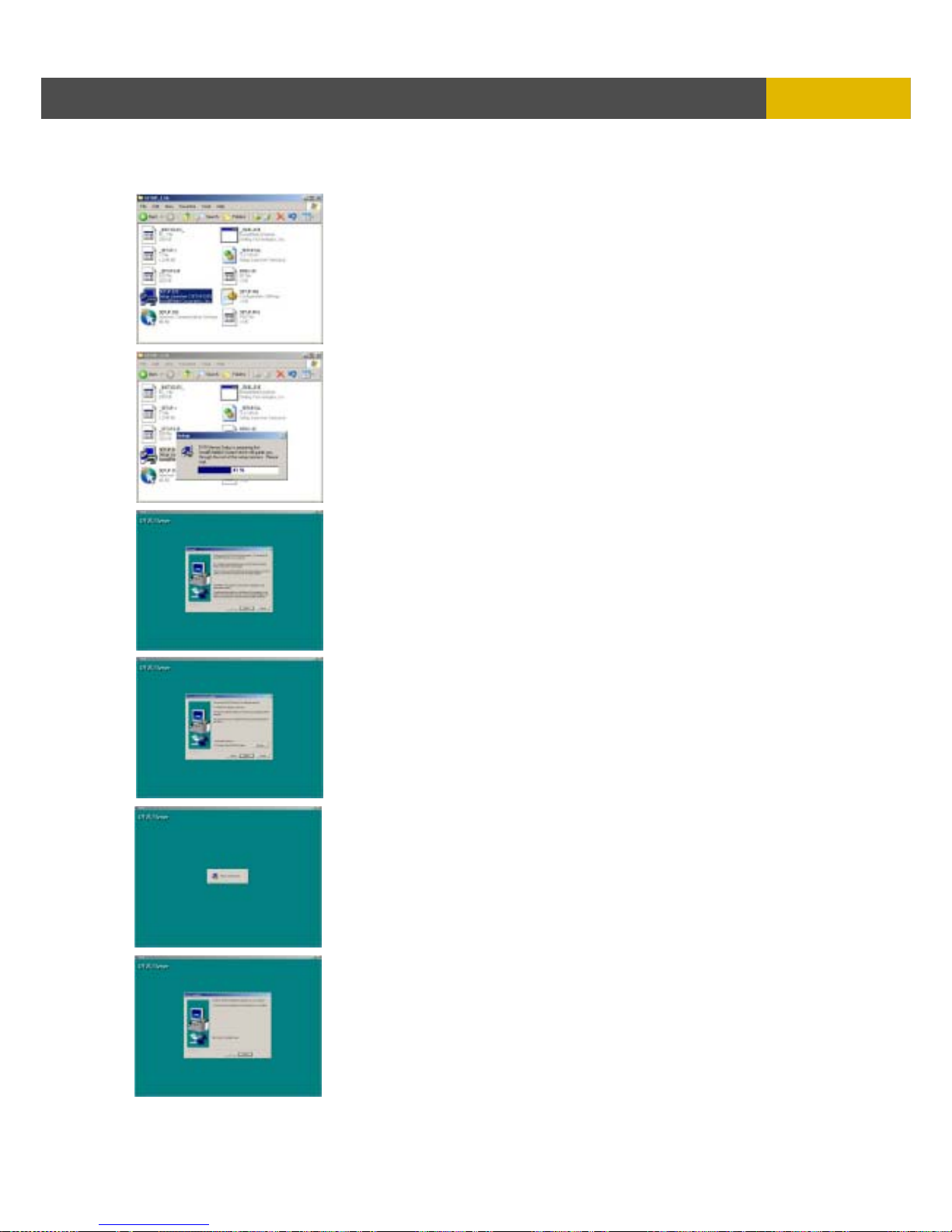
DIGITAL VIDEO RECORDER
95
NETWORK VIEWER INSTALLATION
11.3 INSTALLING THE DVR VIEWER
Insert the program CD into the CD-ROM or DVD-ROM drive of
the computer and locate the SETUP.EXE file.
Double-click on the setup file, and the program will start the
installation.
Click on NEXT.
The DVR viewer will be installed in its default folder of
C:\Program Files\DVR\DVR-Viewer. If the folder needs to be
changed, click on “BROWSE…” button and then select a
different folder.
The setup program will run through its series of installation
process.
Click on FINISH to complete the installation.
Page 96
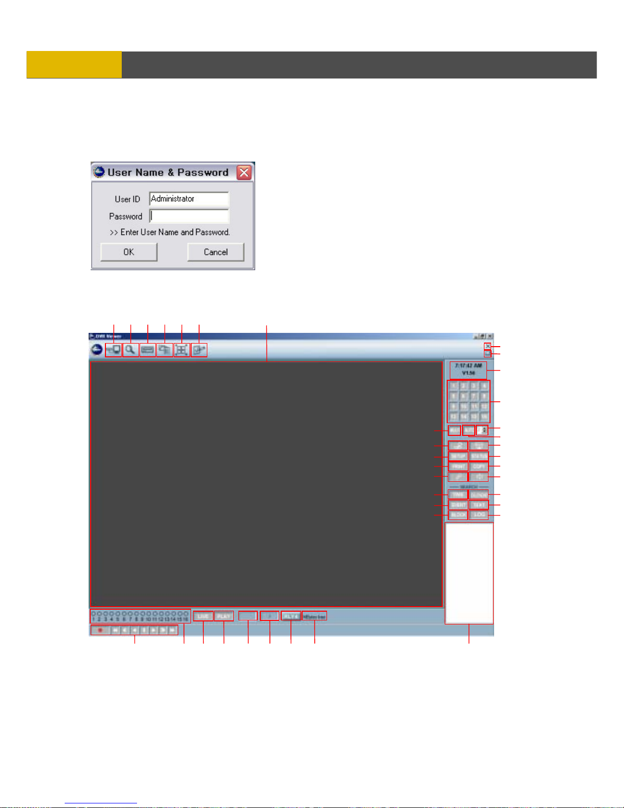
USER’S MANUAL
96
NETWORK VIEWER INSTALLATION
11.4 DVR VIEWER - LAYOUT
Locate the DvrViewer icon on the desktop and double-click on it to run the client software. The
program can also be located in START- Programs – DVR-Viewer.
When the DVR Viewer is run for the first time, it prompts for
the administrator’s password.
Select and enter a password of up to 20 alphanumeric
characters.
Click on OK to start the program.
The DVR Viewer has two display modes. When the
program is run for the first time, it will be shown in the attached mode The DVR Viewer then can
be switched into detached mode to view up to 16 DVR windows simultaneously.
1
16
1
2 3 4 5 6
7
8
9
10
11
12
13
14
15
17
18
19
20
21
22
23
24
25
26
27
28
29 30 31 32 34 35 36 37
33
Page 97
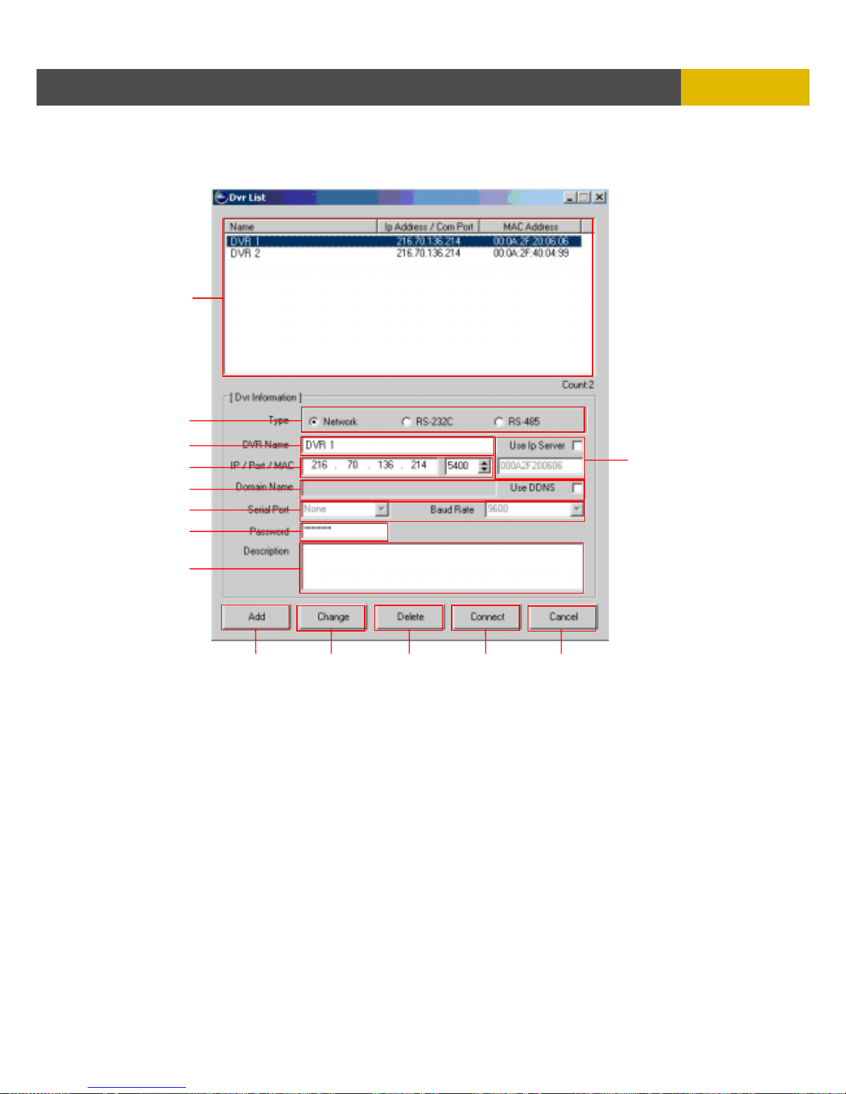
DIGITAL VIDEO RECORDER
97
NETWORK VIEWER INSTALLATION
1. DVR LIST
The DVR List adds or removes individual DVRs and offers a variety of connection options.
a. DVR List
The DVRs that have been added are listed in this box.
b. Connection Type
Select the connection type to the DVR.
c. DVR Name
Enter the DVR name.
d. IP Address and Port
Enter the IP address and the port number for the DVR, if known.
a
b
c
d
e
f
g
h
i
j k l m n
Page 98

USER’S MANUAL
98
NETWORK VIEWER INSTALLATION
e. Use IP Server
The DVR can be located on the internet using the MAC address displayed in the status screen.
If the MAC address is to be used, “Use IP Server” box must be checked.
f. Domain Name / Use DDNS
The DVR can be located on the internet using a domain name, or a web address. The DVR
must be registered with a Dynamic DNS service in order to be located. If the Domain Name is
to be used, “Use DDNS” box must be checked.
g. Serial Port
Select the COM port and the baud rate if RS-232C or RS-485 protocols are used to connect to
the DVR.
h. Password
Enter the password to access the DVR remotely. The password level entered will grant the
access privileges assigned by the administrator.
i. Description
Add comments or notes to the DVR in this box.
j. Add
Once all the information for the DVR has been entered, click on ADD to add to the DVR list.
k. Change
After changing the DVR information, click on CHANGE to update the DVR information.
l. Delete
Highlight a DVR from the DVR List and then click on DELETE to remove from the DVR List.
m. Connect
Highlight a DVR from the DVR List and then click on CONNECT to remotely connect to the DVR.
n. Cancel
Click on CANCEL to exit from the DVR List menu.
Page 99
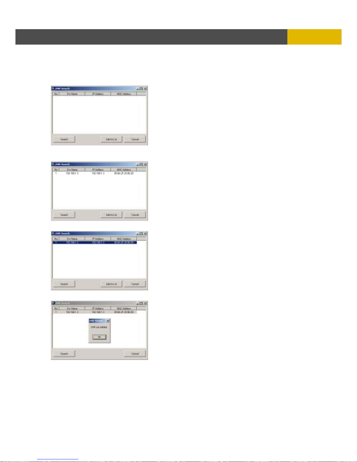
DIGITAL VIDEO RECORDER
99
NETWORK VIEWER INSTALLATION
2. DVR SEARCH
Within a local area network environment (LAN), it is possible to automatically scan and list available
DVRs to be added to the DVR list.
Click on DVR SEARCH to open the DVR Search
window.
Click on SEARCH, and available DVRs will be listed.
Highlight a desired DVR to add to the DVR List, and
then click on ADD TO LIST.
“DVR List Added.” Message will appear with a
successful addition to the DVR list.
Click on CANCEL to exit from DVR Search.
Page 100
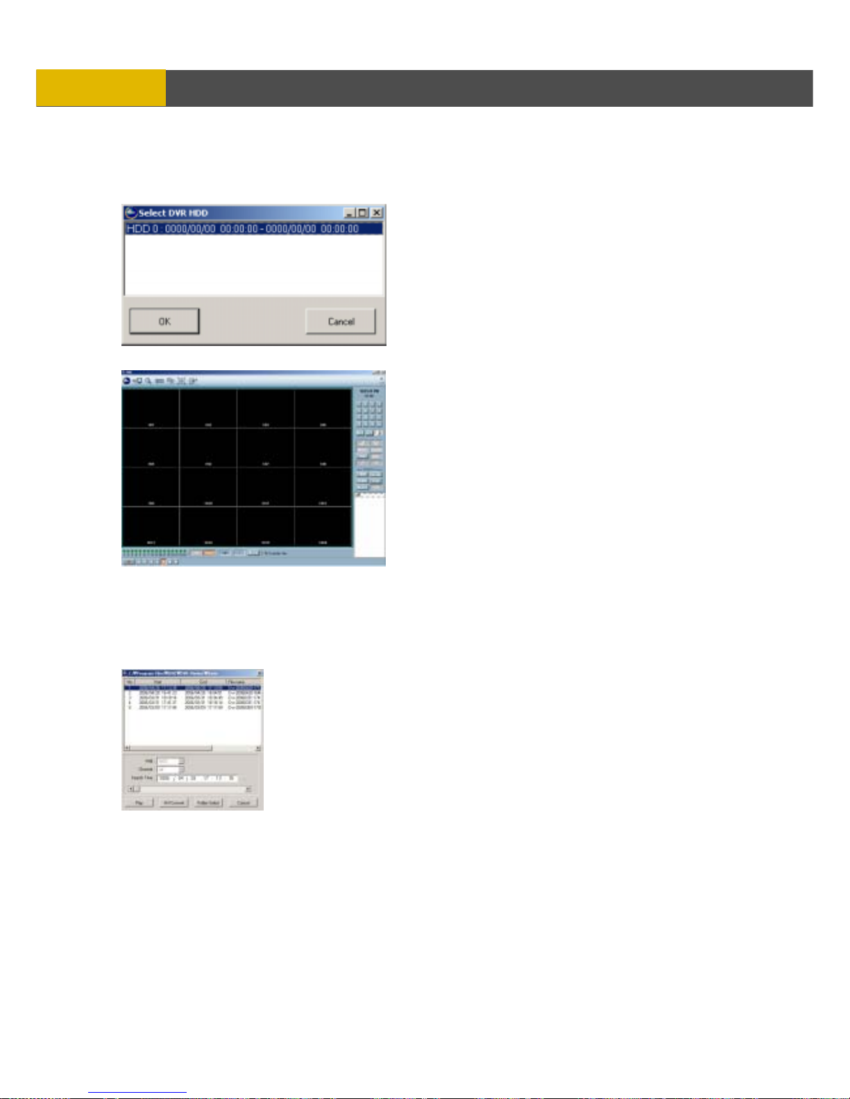
USER’S MANUAL
100
NETWORK VIEWER INSTALLATION
3. HDD SEARCH
The hard disk drive from the DVR can be directly connected to a PC, where the files can be
searched and played back through the DVR Viewer.
Click on HDD SEARCH to open the HDD
Search window
Select a hard disk drive, and then click on OK.
Recorded channels will be shown in the main
channel display window.
The content of the hard drive can be further
searched and played back using any one of
the search features, or using the playback
buttons to playback in slow, fast, or paused
mode.
4. FILE SEARCH
Backed up files and files that have been downloaded can be searched and played back.
Click on FILE SEARCH to open the File Search window.
 Loading...