

Hardware User Manual
EA1-MG6-USER-M
®
6-inch Micro-Graphic Panel
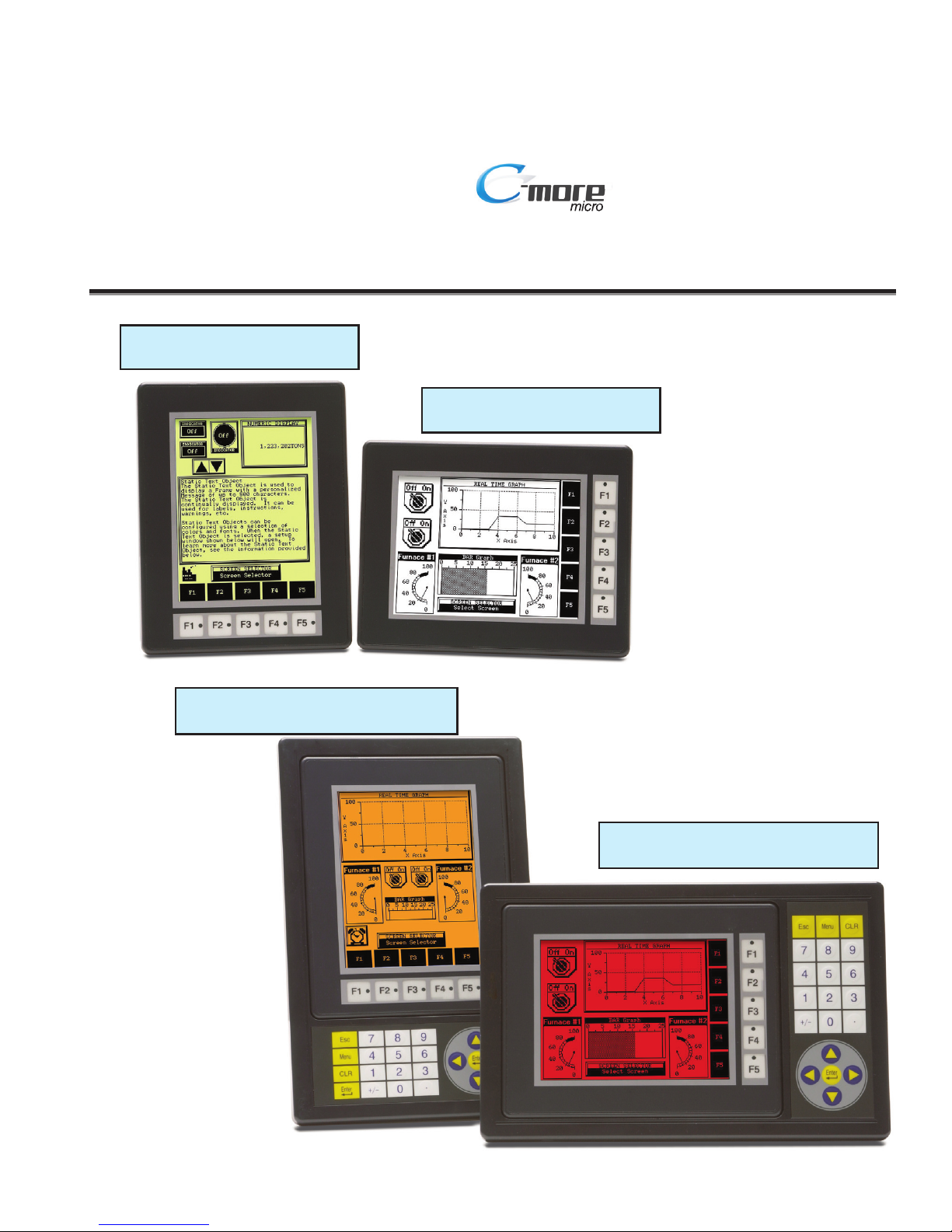
C-more 6” Micro-Graphic Panel
EA1-S6MLW - shown in Landscape Mode
C-more 6” Micro-Graphic Panel Installed in a
20-button Landscape Keypad Bezel EA-MG6-BZ2
C-more 6” Micro-Graphic Panel
EA1-S6ML - shown in Portrait Mode
C-more 6” Micro-Graphic Panel Installed in a
21-button Portrait Keypad Bezel EA-MG6-BZ2P

Graphic Panel - 6 Inch
HARDWARE USER MANUAL
Please include the Manual Number and the Manual Issue, both shown below,
when communicating with Technical Support regarding this publication.
Manual Number: EA1-MG6-USER-M
Issue: 1st Edition Rev C.
Issue Date: 09/10
Publication History
Issue Date Description of Changes
1st Edition 07/08 Original issue
Rev. A 10/08 Added CLICK PLC.
Rev. B 10/08 Added Mitsubishi Q / QnA
Rev. C 09/10 Added Allen Bradley PLC DF1 imformation and made minor corrections
®


WARNING
Thank you for purchasing automation equipment from Automationdirect.com®, doing business as,
AutomationDirect. We want your new automation equipment to operate safely. Anyone who installs or
uses this equipment should read this publication (and any other relevant publications) before installing or
operating the equipment.
To minimize the risk of potential safety problems, you should follow all applicable local and national codes
that regulate the installation and operation of your equipment. These codes vary from area to area and
usually change with time. It is your responsibility to determine which codes should be followed, and to
verify that the equipment, installation, and operation is in compliance with the latest revision of these
codes.
At a minimum, you should follow all applicable sections of the National Fire Code, National Electrical
Code, and the codes of the National Electrical Manufacturer's Association (NEMA). There may be local
regulatory or government offices that can also help determine which codes and standards are necessary for
safe installation and operation.
Equipment damage or serious injury to personnel can result from the failure to follow all applicable codes
and standards. We do not guarantee the products described in this publication are suitable for your
particular application, nor do we assume any responsibility for your product design, installation, or
operation.
Our products are not fault-tolerant and are not designed, manufactured or intended for use or resale as online control equipment in hazardous environments requiring fail-safe performance, such as in the
operation of nuclear facilities, aircraft navigation or communication systems, air traffic control, direct life
support machines, or weapons systems, in which the failure of the product could lead directly to death,
personal injury, or severe physical or environmental damage ("High Risk Activities"). AutomationDirect
specifically disclaims any expressed or implied warranty of fitness for High Risk Activities.
For additional warranty and safety information, see the Terms and Conditions section of our catalog. If
you have any questions concerning the installation or operation of this equipment, or if you need
additional information, please call us at 770-844-4200.
This publication is based on information that was available at the time it was printed. At
AutomationDirect we constantly strive to improve our products and services, so we reserve the right to
make changes to the products and/or publications at any time without notice and without any obligation.
This publication may also discuss features that may not be available in certain revisions of the product.
Trademarks
This publication may contain references to products produced and/or offered by other companies. The
product and company names may be trademarked and are the sole property of their respective owners.
AutomationDirect disclaims any proprietary interest in the marks and names of others.
Copyright 2006-2010, Automationdirect.com®Incorporated
All Rights Reserved
No part of this manual shall be copied, reproduced, or transmitted in any way without the prior, written
consent of Automationdirect.com
®
Incorporated. AutomationDirect retains the exclusive rights to all
information included in this document.

ADVERTENCIA
Gracias por comprar equipo de automatización de Automationdir ect.com®. Deseamos que su nuevo equipo de
automatización opere de manera segura. Cualquier persona que instale o use este equipo debe leer esta
publicación (y cualquier otra publicación pertinente) antes de instalar u operar el equipo.
Para reducir al mínimo el riesgo debido a problemas de seguridad, debe seguir todos los códigos de seguridad
locales o nacionales aplicables que regulan la instalación y operación de su equipo. Estos códigos varian de área
en área y usualmente cambian con el tiempo. Es su responsabilidad determinar cuales códigos deben ser
seguidos y verificar que el equipo, instalación y operación estén en cumplimiento con la revisión mas reciente
de estos códigos.
Como mínimo, debe seguir las secciones aplicables del Código Nacional de Incendio, Código Nacional
Eléctrico, y los códigos de (NEMA) la Asociación Nacional de Fabricantes Eléctricos de USA. Puede haber
oficinas de normas locales o del gobierno que pueden ayudar a determinar cuales códigos y normas son
necesarios para una instalación y operación segura.
Si no se siguen todos los códigos y normas aplicables, puede resultar en daños al equipo o lesiones serias a
personas. No garantizamos los productos descritos en esta publicación para ser adecuados para su aplicación en
particular, ni asumimos ninguna responsabilidad por el diseño de su producto, la instalación u operación.
Nuestros productos no son tolerantes a fallas y no han sido diseñados, fabricados o intencionados para uso o
reventa como equipo de control en línea en ambientes peligrosos que requieren una ejecución sin fallas, tales
como operación en instalaciones nucleares, sistemas de navegación aérea, o de comunicación, control de tráfico
aéreo, máquinas de soporte de vida o sistemas de armamentos en las cuales la falla del producto puede resultar
directamente en muerte, heridas personales, o daños físicos o ambientales severos ("Actividades de Alto Riesgo").
Automationdirect.com específicamente rechaza cualquier garantía ya sea expresada o implicada para
actividades de alto riesgo.
Para información adicional acerca de garantía e información de seguridad, vea la sección de Términos y
Condiciones de nuestro catálogo. Si tiene alguna pregunta sobre instalación u operación de este equipo, o si
necesita información adicional, por favor llámenos al número 770-844-4200 en Estados Unidos.
Esta publicación está basada en la información disponible al momento de impresión. En
Automationdirect.com nos esforzamos constantemente para mejorar nuestros productos y servicios, así que
nos reservamos el derecho de hacer cambios al producto y/o a las publicaciones en cualquier momento sin
notificación y sin ninguna obligación. Esta publicación también puede discutir características que no estén
disponibles en ciertas revisiones del producto
.
Marcas Registradas
Esta publicación puede contener referencias a productos producidos y/u ofrecidos por otras compañías. Los nombres de las
compañías y productos pueden tener marcas registradas y son propiedad única de sus respectivos dueños. Automationdirect.com,
renuncia cualquier interés propietario en las marcas y nombres de otros.
PROPIEDAD LITERARIA 2006-2010, AUTOMATIONDIRECT.COM®INCORPORATED
Todos los derechos reservados
No se permite copiar, reproducir, o transmitir de ninguna forma ninguna parte de este manual sin previo consentimiento por escrito de
Automationdirect.com
®
Incorprated. Automationdirect.com retiene los derechos exclusivos a toda la información incluida en este
documento. Los usuarios de este equipo pueden copiar este documento solamente para instalar, configurar y mantener el equipo
correspondiente. También las instituciones de enseñanza pueden usar este manual para propósitos educativos.

AVERTISSEMENT
Nous vous remercions d'avoir acheté l'équipement d'automatisation de Automationdirect.com®, en faisant des
affaires comme, AutomationDirect. Nous tenons à ce que votre nouvel équipement d'automatisation fonctionne en
toute sécurité. Toute personne qui installe ou utilise cet équipement doit lire la présente publication (et toutes les
autres publications pertinentes) avant de l'installer ou de l'utiliser.
Afin de réduire au minimum le risque d'éventuels problèmes de sécurité, vous devez respecter tous les codes locaux et
nationaux applicables régissant l'installation et le fonctionnement de votre équipement. Ces codes diffèrent d'une
région à l'autre et, habituellement, évoluent au fil du temps. Il vous incombe de déterminer les codes à respecter et
de vous assurer que l'équipement, l'installation et le fonctionnement sont conformes aux exigences de la version la
plus récente de ces codes.
Vous devez, à tout le moins, respecter toutes les sections applicables du Code national de prévention des incendies,
du Code national de l'électricité et des codes de la National Electrical Manufacturer's Association (NEMA). Des
organismes de réglementation ou des services gouvernementaux locaux peuvent également vous aider à déterminer
les codes ainsi que les normes à respecter pour assurer une installation et un fonctionnement sûrs.
L'omission de respecter la totalité des codes et des normes applicables peut entraîner des dommages à l'équipement
ou causer de graves blessures au personnel. Nous ne garantissons pas que les produits décrits dans cette publication
conviennent à votre application particulière et nous n'assumons aucune responsabilité à l'égard de la conception, de
l'installation ou du fonctionnement de votre produit.
Nos produits ne sont pas insensibles aux défaillances et ne sont ni conçus ni fabriqués pour l'utilisation ou la revente
en tant qu'équipement de commande en ligne dans des environnements dangereux nécessitant une sécurité absolue,
par exemple, l'exploitation d'installations nucléaires, les systèmes de navigation aérienne ou de communication, le
contrôle de la circulation aérienne, les équipements de survie ou les systèmes d'armes, pour lesquels la défaillance du
produit peut provoquer la mort, des blessures corporelles ou de graves dommages matériels ou environnementaux
(«activités à risque élevé»). La société AutomationDirect nie toute garantie expresse ou implicite d'aptitude à
l'emploi en ce qui a trait aux activités à risque élevé.
Pour des renseignements additionnels touchant la garantie et la sécurité, veuillez consulter la section Modalités et
conditions de notre documentation. Si vous avez des questions au sujet de l'installation ou du fonctionnement de cet
équipement, ou encore si vous avez besoin de renseignements supplémentaires, n'hésitez pas à nous téléphoner au
770-844-4200.
Cette publication s'appuie sur l'information qui était disponible au moment de l'impression. À la société
AutomationDirect, nous nous efforçons constamment d'améliorer nos produits et services. C'est pourquoi nous
nous réservons le droit d'apporter des modifications aux produits ou aux publications en tout temps, sans préavis ni
quelque obligation que ce soit. La présente publication peut aussi porter sur des caractéristiques susceptibles de ne
pas être offertes dans certaines versions révisées du produit.
Marques de commerce
La présente publication peut contenir des références à des produits fabriqués ou offerts par d'autres entreprises. Les
désignations des produits et des entreprises peuvent être des marques de commerce et appartiennent exclusivement à
leurs propriétaires respectifs. AutomationDirect nie tout intérêt dans les autres marques et désignations.
Copyright 2006-2010, Automationdirect.com®Incorporated
Tous droits réservés
Nulle partie de ce manuel ne doit être copiée, reproduite ou transmise de quelque façon que ce soit sans le
consentement préalable écrit de la société Automationdirect.com
®
Incorporated. AutomationDirect conserve les
droits exclusifs à l'égard de tous les renseignements contenus dans le présent document.


TABL E OF CON TEN TS
Chapter 1: Getting Started . . . . . . . . . . . . . . . . . . . . . . . . . . . . . . . . .1–1
Introduction . . . . . . . . . . . . . . . . . . . . . . . . . . . . . . . . . . . . . . . . . . . . . . . . . . . . . . .1–2
Conventions Used . . . . . . . . . . . . . . . . . . . . . . . . . . . . . . . . . . . . . . . . . . . . . . . . . . .1–3
Product Overview . . . . . . . . . . . . . . . . . . . . . . . . . . . . . . . . . . . . . . . . . . . . . . . . . . .1–4
Agency Approvals . . . . . . . . . . . . . . . . . . . . . . . . . . . . . . . . . . . . . . . . . . . . . . . . . . .1–4
Part Number Key . . . . . . . . . . . . . . . . . . . . . . . . . . . . . . . . . . . . . . . . . . . . . . . . . . .1–5
Product Label Example: . . . . . . . . . . . . . . . . . . . . . . . . . . . . . . . . . . . . . . . . . . . . . .1–5
Serial Number and Date Code format: . . . . . . . . . . . . . . . . . . . . . . . . . . . . . . . . . .1–5
Quick Start Steps . . . . . . . . . . . . . . . . . . . . . . . . . . . . . . . . . . . . . . . . . . . . . . . . . . . .1–6
Step 1 – Unpack and Inspect . . . . . . . . . . . . . . . . . . . . . . . . . . . . . . . . . . . . . . . . . .1–6
Step 2 – Install Optional Hardware Accessories . . . . . . . . . . . . . . . . . . . . . . . . . . . .1–7
Step 3 – Become Familiar with Available Communication Ports . . . . . . . . . . . . . . . .1–8
Step 4 – Install C-more 6” Micro-Graphic Panel . . . . . . . . . . . . . . . . . . . . . . . . . . . .1–9
Enclosure Clearances . . . . . . . . . . . . . . . . . . . . . . . . . . . . . . . . . . . . . . . . . . . . . . .1–10
Step 5 – Connect C-more 6” Micro-Graphic Panel to Computer . . . . . . . . . . . . . .1–11
Step 6 – Provide Power to the C-more 6” Micro-Graphic Panel . . . . . . . . . . . . . . .1–12
Step 7 – Accessing the C-more 6” Micro-Graphic Panel Setup Screens . . . . . . . . .1–13
Step 8 – Choose C-more 6” Micro-Graphic Panel to PLC Protocol & Cables . . . . .1–14
Step 9 – Install the Programming Software and Develop a Project . . . . . . . . . . . .1–15
Step 10 – Connect C-more 6” Micro-Graphic Panel to PLC . . . . . . . . . . . . . . . . . .1–16

Chapter 2: Specifications . . . . . . . . . . . . . . . . . . . . . . . . . . . . . . . . . . .2–1
Available Models . . . . . . . . . . . . . . . . . . . . . . . . . . . . . . . . . . . . . . . . . . . . . . . . . . . .2–2
Model Specifications . . . . . . . . . . . . . . . . . . . . . . . . . . . . . . . . . . . . . . . . . . . . . . . . .2–3
Panel Dimensions . . . . . . . . . . . . . . . . . . . . . . . . . . . . . . . . . . . . . . . . . . . . . . . . . . .2–5
Communications Ports . . . . . . . . . . . . . . . . . . . . . . . . . . . . . . . . . . . . . . . . . . . . . . .2–6
Chemical Compatibility . . . . . . . . . . . . . . . . . . . . . . . . . . . . . . . . . . . . . . . . . . . . . . .2–7
Chapter 3: Accessories . . . . . . . . . . . . . . . . . . . . . . . . . . . . . . . . . . . . .3–1
Accessories . . . . . . . . . . . . . . . . . . . . . . . . . . . . . . . . . . . . . . . . . . . . . . . . . . . . . . . .3–2
C-more Micro-Graphic Programming Software . . . . . . . . . . . . . . . . . . . . . . . . . . . .3–3
USB to RS-232 Programming Cable Assembly . . . . . . . . . . . . . . . . . . . . . . . . . . . . .3–6
20-Button Landscape (Horizontal) Keypad Bezel . . . . . . . . . . . . . . . . . . . . . . . . . .3–8
21-Button Portrait (Vertical) Keypad Bezel . . . . . . . . . . . . . . . . . . . . . . . . . . . . . .3–11
D-SUB 15-pin 90-degree Communication Port Adapter . . . . . . . . . . . . . . . . . . . .3–14
D-SUB 15-pin to Terminal Block Adapter . . . . . . . . . . . . . . . . . . . . . . . . . . . . . . . .3–14
Clear Screen Overlay . . . . . . . . . . . . . . . . . . . . . . . . . . . . . . . . . . . . . . . . . . . . . . . .3–15
Chapter 4: Installation and Wiring . . . . . . . . . . . . . . . . . . . . . . . . . . .4–1
Safety Guidelines . . . . . . . . . . . . . . . . . . . . . . . . . . . . . . . . . . . . . . . . . . . . . . . . . . .4–2
Introduction . . . . . . . . . . . . . . . . . . . . . . . . . . . . . . . . . . . . . . . . . . . . . . . . . . . . . . .4–3
Panel Cutout Dimensions (all models) . . . . . . . . . . . . . . . . . . . . . . . . . . . . . . . . . . .4–4
Wiring Guidelines . . . . . . . . . . . . . . . . . . . . . . . . . . . . . . . . . . . . . . . . . . . . . . . . . . .4–5
Chapter 5: System Setup Screens . . . . . . . . . . . . . . . . . . . . . . . . . . . .5–1
Introduction . . . . . . . . . . . . . . . . . . . . . . . . . . . . . . . . . . . . . . . . . . . . . . . . . . . . . . .5–2
Accessing the System Setup Screens . . . . . . . . . . . . . . . . . . . . . . . . . . . . . . . . . . . .5–3
System Setup Screens Flowchart . . . . . . . . . . . . . . . . . . . . . . . . . . . . . . . . . . . . . . .5–4
Setup Menu . . . . . . . . . . . . . . . . . . . . . . . . . . . . . . . . . . . . . . . . . . . . . . . . . . . . . . . .5–5
Information Menu . . . . . . . . . . . . . . . . . . . . . . . . . . . . . . . . . . . . . . . . . . . . . . . . . . .5–6
ii
Table of Contents
®
EA1-MG6-USER-M Hardware User Manual, 1st Ed. Rev C, 09/10

Memory . . . . . . . . . . . . . . . . . . . . . . . . . . . . . . . . . . . . . . . . . . . . . . . . . . . . . . . . . .5–6
Protocol . . . . . . . . . . . . . . . . . . . . . . . . . . . . . . . . . . . . . . . . . . . . . . . . . . . . . . . . . .5–6
Extensions . . . . . . . . . . . . . . . . . . . . . . . . . . . . . . . . . . . . . . . . . . . . . . . . . . . . . . . .5–6
Versions . . . . . . . . . . . . . . . . . . . . . . . . . . . . . . . . . . . . . . . . . . . . . . . . . . . . . . . . . .5–6
Setting Menu . . . . . . . . . . . . . . . . . . . . . . . . . . . . . . . . . . . . . . . . . . . . . . . . . . . . . .5–7
LCD Contrast . . . . . . . . . . . . . . . . . . . . . . . . . . . . . . . . . . . . . . . . . . . . . . . . . . . . . .5–7
Backlight, Model EA1-S6ML . . . . . . . . . . . . . . . . . . . . . . . . . . . . . . . . . . . . . . . . . . .5–8
Backlight, Model EA1-S6MLW . . . . . . . . . . . . . . . . . . . . . . . . . . . . . . . . . . . . . . . . .5–9
Beep . . . . . . . . . . . . . . . . . . . . . . . . . . . . . . . . . . . . . . . . . . . . . . . . . . . . . . . . . . .5–10
Calibration . . . . . . . . . . . . . . . . . . . . . . . . . . . . . . . . . . . . . . . . . . . . . . . . . . . . . . .5–11
Clear User Memory . . . . . . . . . . . . . . . . . . . . . . . . . . . . . . . . . . . . . . . . . . . . . . . .5–12
Reset to Factory Default . . . . . . . . . . . . . . . . . . . . . . . . . . . . . . . . . . . . . . . . . . . . .5–12
Hourglass . . . . . . . . . . . . . . . . . . . . . . . . . . . . . . . . . . . . . . . . . . . . . . . . . . . . . . . .5–13
Rotation . . . . . . . . . . . . . . . . . . . . . . . . . . . . . . . . . . . . . . . . . . . . . . . . . . . . . . . . .5–14
Test Menu . . . . . . . . . . . . . . . . . . . . . . . . . . . . . . . . . . . . . . . . . . . . . . . . . . . . . . . .5–15
Serial Port1 - Loop Back Test . . . . . . . . . . . . . . . . . . . . . . . . . . . . . . . . . . . . . . . . .5–15
Serial Port2 - Loop Back Test . . . . . . . . . . . . . . . . . . . . . . . . . . . . . . . . . . . . . . . . .5–16
PLC Enquiry Test . . . . . . . . . . . . . . . . . . . . . . . . . . . . . . . . . . . . . . . . . . . . . . . . . .5–17
Buzzer Test . . . . . . . . . . . . . . . . . . . . . . . . . . . . . . . . . . . . . . . . . . . . . . . . . . . . . .5–17
Touch Panel Test . . . . . . . . . . . . . . . . . . . . . . . . . . . . . . . . . . . . . . . . . . . . . . . . . .5–18
Exit . . . . . . . . . . . . . . . . . . . . . . . . . . . . . . . . . . . . . . . . . . . . . . . . . . . . . . . . . . . . . .5–18
Chapter 6: PLC Communications . . . . . . . . . . . . . . . . . . . . . . . . . . . . .6–1
Introduction . . . . . . . . . . . . . . . . . . . . . . . . . . . . . . . . . . . . . . . . . . . . . . . . . . . . . .6–2
Available PLC Protocols . . . . . . . . . . . . . . . . . . . . . . . . . . . . . . . . . . . . . . . . . . . . . .6–3
C-more 6” Micro-Graphic Communication Ports . . . . . . . . . . . . . . . . . . . . . . . . . . .6–4
DirectLOGIC PLCs Password Protection . . . . . . . . . . . . . . . . . . . . . . . . . . . . . . . . . .6–6
PLC Compatibility and Connection Charts . . . . . . . . . . . . . . . . . . . . . . . . . . . . . . .6–6
AutomationDirect CLICK PLC: . . . . . . . . . . . . . . . . . . . . . . . . . . . . . . . . . . . . . . . . .6–6
Direct LOGIC PLCs RS-422A/RS-485A: . . . . . . . . . . . . . . . . . . . . . . . . . . . . . . . . . . .6–7
Allen-Bradley: . . . . . . . . . . . . . . . . . . . . . . . . . . . . . . . . . . . . . . . . . . . . . . . . . . . . . .6–7
GE, Mitsubishi, Omron, Modicon and Siemens: . . . . . . . . . . . . . . . . . . . . . . . . . . . .6–7
How to use the PLC Compatibility and Connection Charts . . . . . . . . . . . . . . . . . . .6–8
Example: . . . . . . . . . . . . . . . . . . . . . . . . . . . . . . . . . . . . . . . . . . . . . . . . . . . . . . . . .6–8
Cables from AutomationDirect . . . . . . . . . . . . . . . . . . . . . . . . . . . . . . . . . . . . . . . .6–15
Cables from AutomationDirect – Wiring Diagrams . . . . . . . . . . . . . . . . . . . . . . . .6–17
iii
Table of Contents
EA1-MG6-USER-M Hardware User Manual, 1st Ed. Rev C, 09/10
®

User Constructed Cables – Wiring Diagrams . . . . . . . . . . . . . . . . . . . . . . . . . . . . .6–26
RS-422A/RS-485A Multi-Drop Wiring Diagram Examples . . . . . . . . . . . . . . . . . . .6–34
Chapter 7: Maintenance . . . . . . . . . . . . . . . . . . . . . . . . . . . . . . . . . . . .7–1
Project Backup . . . . . . . . . . . . . . . . . . . . . . . . . . . . . . . . . . . . . . . . . . . . . . . . . . . . . .7–2
Check Operating Environment . . . . . . . . . . . . . . . . . . . . . . . . . . . . . . . . . . . . . . . . .7–2
Check Operating Voltage . . . . . . . . . . . . . . . . . . . . . . . . . . . . . . . . . . . . . . . . . . . . .7–2
Check Transmit and Receive Indicators . . . . . . . . . . . . . . . . . . . . . . . . . . . . . . . . . .7–3
Check Physical Conditions . . . . . . . . . . . . . . . . . . . . . . . . . . . . . . . . . . . . . . . . . . . .7–3
Run Tests under the System Setup Screens . . . . . . . . . . . . . . . . . . . . . . . . . . . . . . .7–4
Check Settings under the System Setup Screens . . . . . . . . . . . . . . . . . . . . . . . . . .7–5
Cleaning the Display Screen . . . . . . . . . . . . . . . . . . . . . . . . . . . . . . . . . . . . . . . . . . .7–5
Check Project Functionality . . . . . . . . . . . . . . . . . . . . . . . . . . . . . . . . . . . . . . . . . . .7–6
Checks from the C-more Micro-Graphic Programming Software . . . . . . . . . . . . . .7–6
Chapter 8: Troubleshooting . . . . . . . . . . . . . . . . . . . . . . . . . . . . . . . . .8–1
C-more Micro-Graphic Panel does not Power up . . . . . . . . . . . . . . . . . . . . . . . . . . .8–2
Display is Blank . . . . . . . . . . . . . . . . . . . . . . . . . . . . . . . . . . . . . . . . . . . . . . . . . . . . .8–2
Display is Dim . . . . . . . . . . . . . . . . . . . . . . . . . . . . . . . . . . . . . . . . . . . . . . . . . . . . . .8–3
No User Program . . . . . . . . . . . . . . . . . . . . . . . . . . . . . . . . . . . . . . . . . . . . . . . . . . .8–3
Lost Firmware – Red ‘Update Mode’ Screen Displayed . . . . . . . . . . . . . . . . . . . . . .8–4
Updating Firmware . . . . . . . . . . . . . . . . . . . . . . . . . . . . . . . . . . . . . . . . . . . . . . . . . .8–4
No Communications between Panel and PC (Personal Computer) . . . . . . . . . . . .8–5
No Communications between Panel and PLC . . . . . . . . . . . . . . . . . . . . . . . . . . . . .8–7
Panel & PLC Error Codes . . . . . . . . . . . . . . . . . . . . . . . . . . . . . . . . . . . . . . . . . . . . .8–8
C-more Micro-Graphic Panel Runtime Errors . . . . . . . . . . . . . . . . . . . . . . . . . . . . . .8–9
Electrical Noise Problems . . . . . . . . . . . . . . . . . . . . . . . . . . . . . . . . . . . . . . . . . . . .8–10
Chapter 9: Replacement Parts . . . . . . . . . . . . . . . . . . . . . . . . . . . . . . .9–1
Replacement Parts Overview . . . . . . . . . . . . . . . . . . . . . . . . . . . . . . . . . . . . . . . . . .9–2
Replacement Parts . . . . . . . . . . . . . . . . . . . . . . . . . . . . . . . . . . . . . . . . . . . . . . . . . .9–2
iv
Table of Contents
®
EA1-MG6-USER-M Hardware User Manual, 1st Ed. Rev C, 09/10

Customizing the Function Keys Insert Label . . . . . . . . . . . . . . . . . . . . . . . . . . . . . .9–3
Appendix A: PLC Protocol Error Codes . . . . . . . . . . . . . . . . . . . . . . . .A–1
Introduction . . . . . . . . . . . . . . . . . . . . . . . . . . . . . . . . . . . . . . . . . . . . . . . . . . . . . . .A–2
C-more Micro-Graphic Panel Error Code Table . . . . . . . . . . . . . . . . . . . . . . . . . . . .A–3
Modbus Protocols Error Code P499 Explanation . . . . . . . . . . . . . . . . . . . . . . . . . .A–4
AutomationDirect CLICK . . . . . . . . . . . . . . . . . . . . . . . . . . . . . . . . . . . . . . . . . . . . .A–4
AutomationDirect DirectLOGIC - Modbus (Koyo) . . . . . . . . . . . . . . . . . . . . . . . . . . .A–4
Modicon Modbus RTU . . . . . . . . . . . . . . . . . . . . . . . . . . . . . . . . . . . . . . . . . . . . . .A–4
Entivity Modbus RTU . . . . . . . . . . . . . . . . . . . . . . . . . . . . . . . . . . . . . . . . . . . . . . . .A–4
DirectLOGIC Error Code P499 Explanation . . . . . . . . . . . . . . . . . . . . . . . . . . . . . . .A–5
DirectLOGIC – K-Sequence PLC Error Code Table . . . . . . . . . . . . . . . . . . . . . . . . . .A–5
DirectLOGIC – DirectNET PLC Error Codes . . . . . . . . . . . . . . . . . . . . . . . . . . . . . . . .A–5
Allen-Bradley Error Code P499 Explanation . . . . . . . . . . . . . . . . . . . . . . . . . . . . . .A–6
Allen-Bradley DF1 Protocol – PLC Error Code Tables . . . . . . . . . . . . . . . . . . . . . . .A–7
Allen-Bradley DH485 Protocol – PLC Error Code Tables . . . . . . . . . . . . . . . . . . . . .A–9
GE Error Code P499 Explanation . . . . . . . . . . . . . . . . . . . . . . . . . . . . . . . . . . . . . .A–11
GE SNPX Protocol – PLC Error Code Tables . . . . . . . . . . . . . . . . . . . . . . . . . . . . .A–12
Mitsubishi FX Protocol – PLC Error Codes . . . . . . . . . . . . . . . . . . . . . . . . . . . . . . .A–21
Mitsubishi Q / QnA and Q Series – PLC Error Codes . . . . . . . . . . . . . . . . . . . . . .A–21
Omron Error Code P499 Explanation . . . . . . . . . . . . . . . . . . . . . . . . . . . . . . . . . .A–23
Omron Host Link Protocol – PLC Error Code Table . . . . . . . . . . . . . . . . . . . . . . . .A–24
Omron FINS Protocol – PLC Error Code Table . . . . . . . . . . . . . . . . . . . . . . . . . . . .A–25
Siemens Error Code P499 Explanation . . . . . . . . . . . . . . . . . . . . . . . . . . . . . . . . .A–28
Siemens PPI Protocol – PLC Error Code Table . . . . . . . . . . . . . . . . . . . . . . . . . . . .A–29
Appendix B: C-more Micro-Graphic Panel Runtime Errors . . . . . . . . .B–1
Introduction . . . . . . . . . . . . . . . . . . . . . . . . . . . . . . . . . . . . . . . . . . . . . . . . . . . . . . .B–2
Runtime Errors . . . . . . . . . . . . . . . . . . . . . . . . . . . . . . . . . . . . . . . . . . . . . . . . . . . . .B–2
Index
v
Table of Contents
EA1-MG6-USER-M Hardware User Manual, 1st Ed. Rev C, 09/10
®


1
1
GETTING STARTE D
CH
CHAPTER
CHAPTER
In This Chapter...
Introduction . . . . . . . . . . . . . . . . . . . . . . . . . . . . . . . . . . . . . . . . . . . . . . . . . . . . . . .1–2
Conventions Used . . . . . . . . . . . . . . . . . . . . . . . . . . . . . . . . . . . . . . . . . . . . . . . . . . .1–3
Product Overview . . . . . . . . . . . . . . . . . . . . . . . . . . . . . . . . . . . . . . . . . . . . . . . . . . .1–4
Agency Approvals . . . . . . . . . . . . . . . . . . . . . . . . . . . . . . . . . . . . . . . . . . . . . . . . . . .1–4
Part Number Key . . . . . . . . . . . . . . . . . . . . . . . . . . . . . . . . . . . . . . . . . . . . . . . . . . .1–5
Product Label Example: . . . . . . . . . . . . . . . . . . . . . . . . . . . . . . . . . . . . . . . . . . . . . .1–5
Serial Number and Date Code format: . . . . . . . . . . . . . . . . . . . . . . . . . . . . . . . . . .1–5
Quick Start Steps . . . . . . . . . . . . . . . . . . . . . . . . . . . . . . . . . . . . . . . . . . . . . . . . . . . .1–6
Step 1 – Unpack and Inspect . . . . . . . . . . . . . . . . . . . . . . . . . . . . . . . . . . . . . . . . . .1–6
Step 2 – Install Optional Hardware Accessories . . . . . . . . . . . . . . . . . . . . . . . . . . . .1–7
Step 3 – Become Familiar with Available Communication Ports . . . . . . . . . . . . . . . .1–8
Step 4 – Install C-more 6” Micro-Graphic Panel . . . . . . . . . . . . . . . . . . . . . . . . . . . .1–9
Enclosure Clearances . . . . . . . . . . . . . . . . . . . . . . . . . . . . . . . . . . . . . . . . . . . . . . .1–10
Step 5 – Connect C-more 6” Micro-Graphic Panel to Computer . . . . . . . . . . . . . .1–11
Step 6 – Provide Power to the C-more 6” Micro-Graphic Panel . . . . . . . . . . . . . . .1–12
Step 7 – Accessing the C-more 6” Micro-Graphic Panel Setup Screens . . . . . . . . .1–13
Step 8 – Choose C-more 6” Micro-Graphic Panel to PLC Protocol & Cables . . . . .1–14
Step 9 – Install the Programming Software and Develop a Project . . . . . . . . . . . .1–15
Step 10 – Connect C-more 6” Micro-Graphic Panel to PLC . . . . . . . . . . . . . . . . . .1–16

Introduction
The Purpose of this Manual
Thank you for purchasing from our C-more®Micro-Graphic family of products. This manual
describes AutomationDirect.com’s C-more 6” Micro-Graphic panels, their specifications,
included components and available accessories and provides you with important information
for installation, connectivity and setup. The manual shows you how to install, wire and use the
products. It also helps you understand how to interface the panels to other devices in a control
system.
This user manual contains important information for personnel who will install the panels and
accessories, and for the personnel who will be programming the panel. If you understand
control systems making use of operating interfaces such as the C-more Micro-Graphic panels,
our user manuals will provide all the information you need to get, and keep, your system up and
running.
Supplemental Manuals
If you are familiar with industrial control type devices, you may be able to get up and running
with just the aide of the Quick Start Guide that is included with each panel. You may also refer
to the online help that is available in the C-more Micro-Graphic programming software.
Technical Support
We strive to make our manuals the best in the industry. We rely on your feedback to let us know
if we are reaching our goal. If you cannot find the solution to your particular application, or, if
for any reason you need technical assistance, please call us at:
770–844–4200
Our technical support group will work with you to answer your questions. They are available
Monday through Friday from 9:00 A.M. to 6:00 P.M. Eastern Time. We also encourage you to
visit our web site where you can find technical and non-technical information about our
products and our company.
http://www.automationdirect.com
If you have a comment, question or suggestion about any of our products, services, or manuals,
please fill out and return the ‘Suggestions’ card that was included with this manual.
EA1-MG6-USER-M Hardware User Manual, 1st Ed. Rev C, 09/10
1–2
Chapter 1: Getting Started
1
®
Conventions Used
When you see the “notepad” icon in the left-hand margin, the paragraph to its immediate right will be a
special note. The word NOTE: in boldface will mark the beginning of the text.
When you see the “exclamation mark” icon in the left-hand margin, the paragraph to its immediate
right will be a warning. This information could prevent injury, loss of property, or even death (in
extreme cases). The word WARNING: in boldface will mark the beginning of the text.
Key Topics for Each Chapter
The beginning of each chapter will list the key topics
that can be found in that chapter.
EA1-MG6-USER-M Hardware User Manual, 1st Ed. Rev C, 09/10
1–3
Chapter 1: Getting Started
1
®
Getting Started
CHAPTER
1
In This Chapter...
............................ ....................................1-2
...................................... ....................................1-4Spec fications
General Information
Product Overview
The C-more 6” Micro-Graphic panel has a 5.7-inch STN LCD monochrome 320 x 240 dot
display. Model EA1-S6ML has five selectable LED-driven backlight colors including Green,
Red, Amber, Yellow and Lime. Model EA1-S6MLW has five selectable LED-driven backlight
colors including White, Pink1, Pink2, Pink3 and Red. Both models feature five user-defined
function keys, each key with a user-defined red LED indicator. The panels can display up to 40
lines by 78 characters of static text and up to 40 lines by 40 characters of dynamic text with
embedded variables and phrases mixed with graphics at landscape orientation. Portrait
orientation can display 59 characters and 40 lines of static text and 40 lines by 40 characters of
dynamic text. Each model is rated NEMA 4/4X, IP-65 (when mounted correctly, for indoor use
only). The C-more 6” Micro-Graphic panels are powered from a 12-24 VDC power supply or
can operate in low-power mode when powered from the serial communications port of select
AutomationDirect PLCs.
Other features include:
• 1792 KB memory
• Built in RJ12 serial communications port (RS-232)
• Built in 15-pin serial communications port (RS-232/422/485)
• Adjustable contrast
• 2 optional keypad bezels, 20-button landscape and 21-button portrait mount
• Optional replaceable clear screen overlay
• Built in Alarm Control setup that activates beep, backlight flash, customized alarm banner, and red
LED blinking
• Up to 999 screens, limited only by memory usage
• 0 to 50 °C (32 to 122 °F) operating temperature range
• UL, cUL & CE agency approvals (see below for details)
• 2-year warranty from date of purchase
Agency Approvals
EA1-MG6-USER-M Hardware User Manual, 1st Ed. Rev C, 09/10
1–4
Chapter 1: Getting Started
1
®
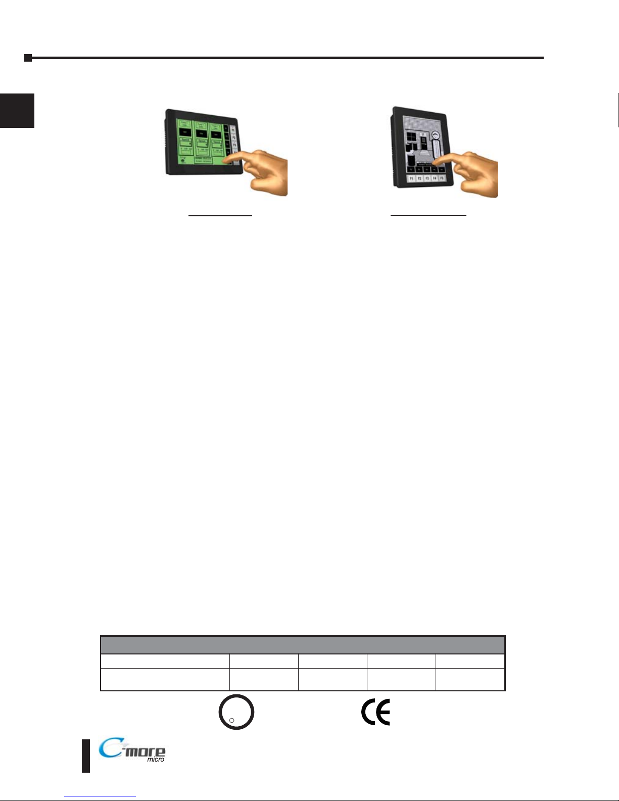
EA1-S6ML
shown in Portrait (Vertical) mode
UL/CUL/CE Certification Numbers
Name UL/CUL UL508 CE ISO-9000
C-more Micro-Graphic Panels
& Accessories
E157382 E157382 EN61131-2 Yes
U
L
C
US
R
EA1-S6MLW
shown in Landscape (Horizontal) mode
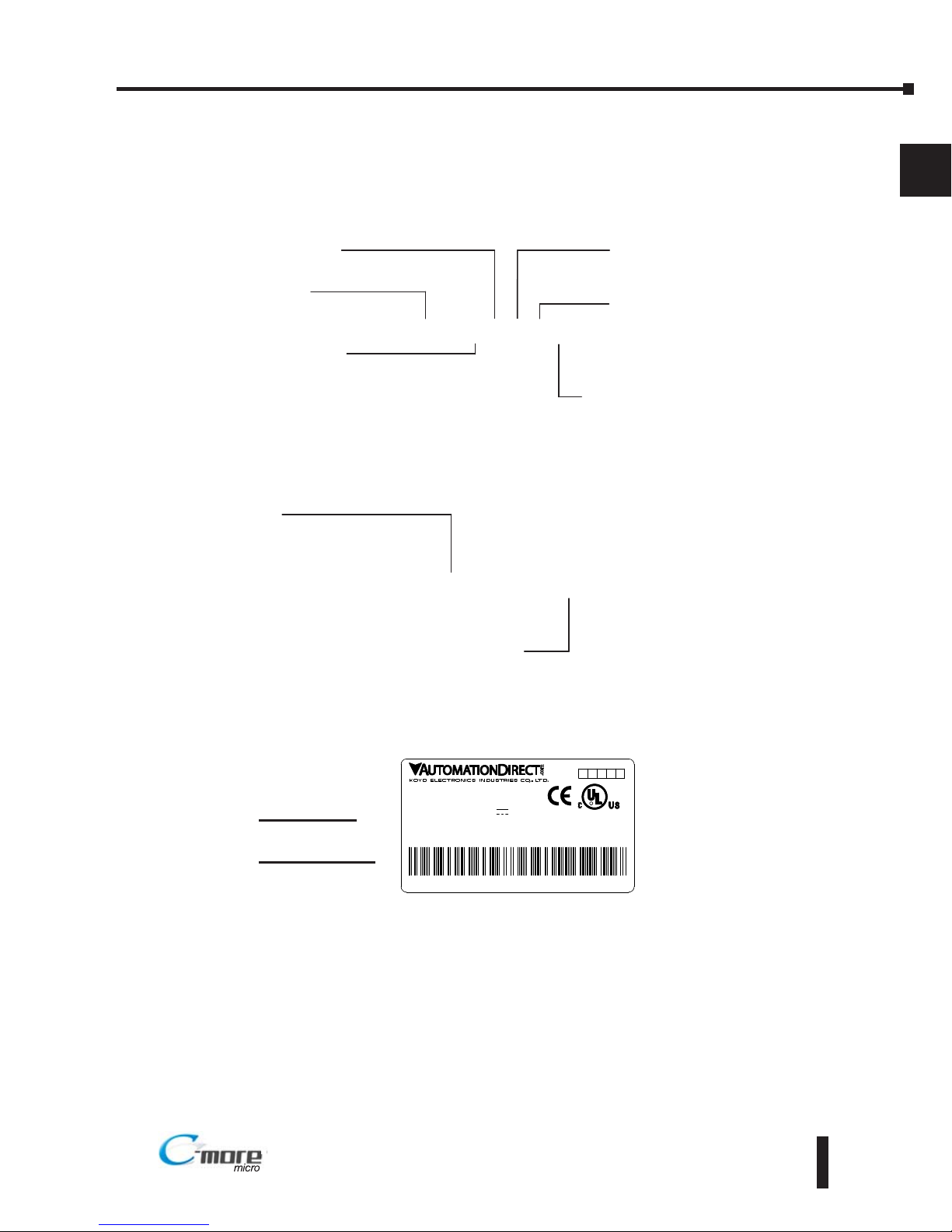
Part Number Key
Panel Part Number Key
The C-more 6” Micro-Graphic panel part numbers consist of the following:
Bezel Part Number Key
The optional C-more 6” Micro-Graphic keypad bezel part numbers consist of the following:
Product Label Example:
Serial Number and Date Code format:
EA1-MG6-USER-M Hardware User Manual, 1st Ed. Rev C, 09/10
1–5
Chapter 1: Getting Started
1
®
EA1-S6MLx
Display Type:
S: STN
Display Color:
M: Monochrome
Features:
blank: Green / Red backlight
W: White / Red backlight
Display Size:
6: 5.7”
Backlight Type:
L: LED
Series Name:
EA1: C more Micro Graphic
LISTED
7M17
Date code:****
5432
1
R01.
D
MADE IN CHINA
M
EA1-S6MLW + serial number
O S6
MODEL:EA1-S6MLW
4 5
INPUT:12-24V 6.5W
IND.CONT.EQ.
EA-MG6-XXXX
Module Type:
BZ2: 20 Key Bezel for landscape mode
BZ2P: 21 Key Bezel for portrait mode
Series Name:
EA MG6: C more 6” Micro Graphic
Bezel Option Module
EA1-S6ML
EA1-S6MLW
YYMF
YY: Year (07 99 --- e.g. 07 2007)
M: Month (1 9, X, Y, Z --- e.g. X Oct.)
DD: Day (1 31)
F: Manufacturing Site (0 9, A Z)
NNN: Sequence number for the date listed (000 999)
Serial Number =
[Part Number]+[YYMDDFNNN]
Date Code =
EA1-MG6-USER-M Hardware User Manual, 1st Ed. Rev C, 09/10
1–6
Chapter 1: Getting Started
1
®
Quick Start Steps
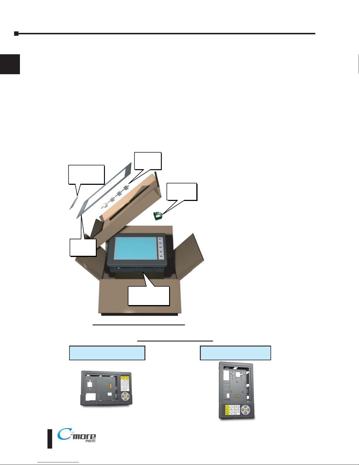
Step 1 – Unpack and Inspect
a.) Unpack the C-more 6” Micro-Graphic panel from its shipping carton. Included in the
carton are the following:
• C-more 6” Micro-Graphic panel (EA1-S6ML or EA1-S6MLW)
• DC power connector (EA-MG-DC-CON)
• cutout template
• mounting clips
• gasket
• function key label inserts
• Quick Start Guide
b.) Unpack any accessories that have
been ordered, such as:
Keypad Bezel, programming
cable, PLC communications
cable, etc.
c.) Inspect all equipment for
completeness. If anything is
missing or damaged,
immediately call the
AutomationDirect®returns
department @ 1-800-633-0405.
Shipping Carton Contents
20-Button Horizontal Keypad Bezel
EA-MG6-BZ2
21-Button Vertical Keypad Bezel
EA-MG6-BZ2P
Optional Accessories
Cutout
Template
Function Key
Label Inserts
Mounting
Clips
C-more 6 Inch
Micro-Graphic
Panel
DC Power
Connector
EA1-MG6-USER-M Hardware User Manual, 1st Ed. Rev C, 09/10
1–7
Chapter 1: Getting Started
1
®
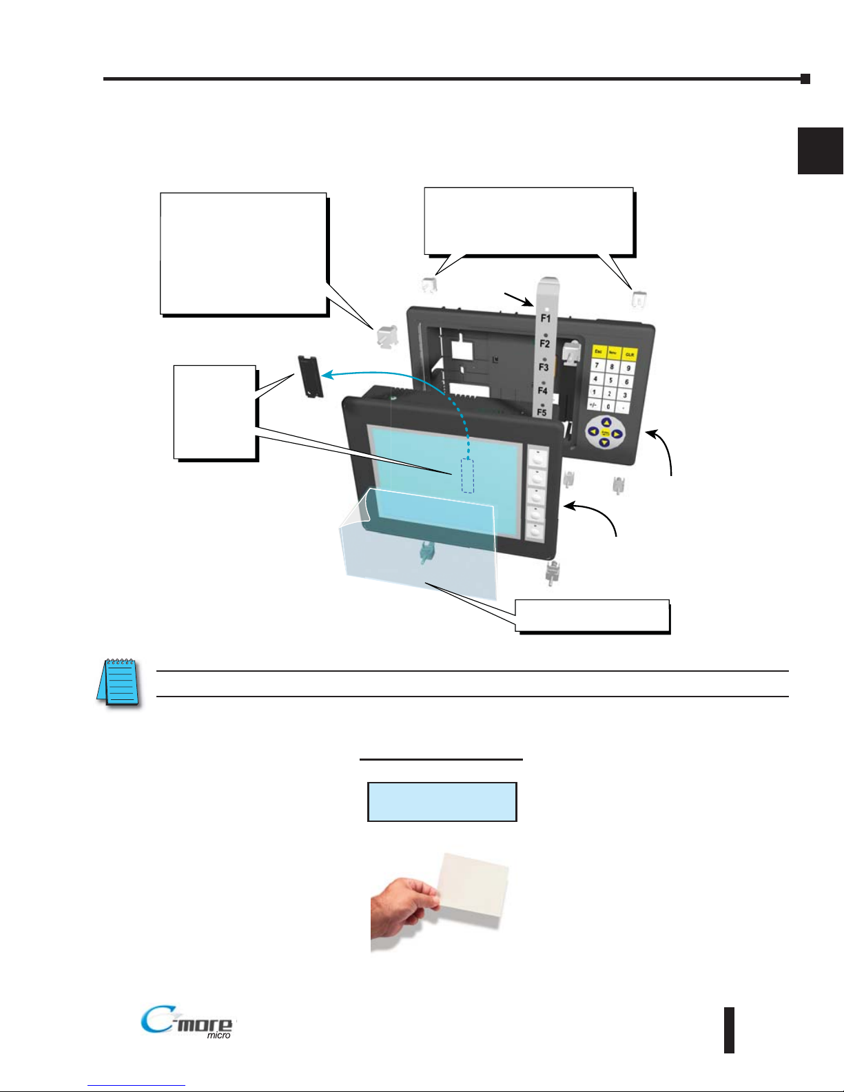
Step 2 – Install Optional Hardware Accessories
Below is an example of a C-more 6” Micro-Graphic panel being assembled with an optional
EA-MG6-BZ2 20-button Keypad Bezel.
C-more 6 Inch
Micro-Graphic Panel
20 Button
Keypad Bezel
EA MG6 BZ2
1. Remove
Expansion
Connector
Protective
Cover from
rear of
panel.
2. Use the (4) Panel Mounting
Clips, EA-MG-BZ2-BRK,
that are supplied with the
panel, to secure panel to
keypad bezel and compress
the gasket between the
panel and the keypad bezel.
Tighten screws to a torque
of 21-28 oz-in [0.15-0.2 Nm].
3. Use (8) Bezel Mounting Clips,
EA-MG-BZ2-BRK, to secure keypad
bezel through enclosure cutout.
Tighten screws to a torque of
21-28 oz-in [0.15-0.2 Nm].
Function
Key Label
Insert
4. Peel Protective Film
from front of panel.
Clear Screen Overlay
EA-6-COV2
Optional Accessory
NOTE: Mounting clips for the panel and keypad bezels are included with the respective product.
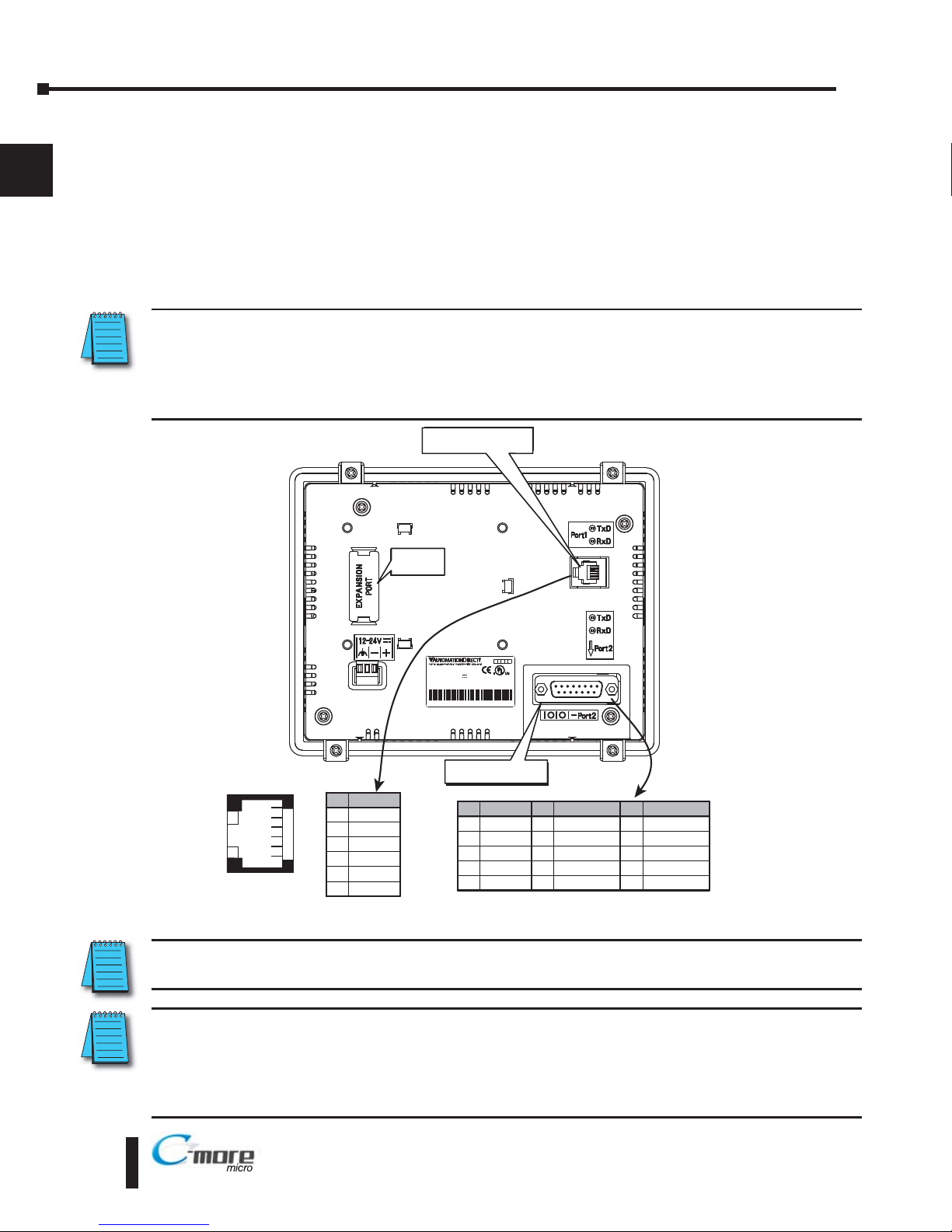
Step 3 – Become Familiar with Available Communication Ports
The C-more 6” Micro-Graphic panel includes a built-in RS-232 serial communications port
designated as Port1. This port uses an RJ12 type telephone jack to make connections to either
the EA-MG-PGM-CBL programming cable assembly or a communications cable, such as an
EA-2CBL, to interface with a PLC or controller. The panel can receive power through this port
from the serial communications port on AutomationDirect CLICK™ and select
Direct LOGIC PLCs. The other serial communications port designated as Port2 is a 15-pin Dsub connector that supports RS-232, RS-485 and RS-422.
NOTE: When the 6” panel is powered through Port1 from a connected PLC or PC, the screen brightness is
diminished because the panel is running in Low-Power Mode. For full brightness, connect an external
12-24 VDC power source to the panel’s power connection. Low-Power Mode is intended for initial
programming. For full brightness, connect an external 12-24 VDC power source when the panel is installed
in its application.
NOTE: See Chapter 2: Specifications and Chapter 6: PLC Communications for additional details on the
available communication ports, protocols and cables.
NOTE: The panel has a built-in RJ12 serial communications port (Port1 - RS-232) and a built in 15-pin serial
communications port (Port2 - RS-232/422/485). Only one of the ports can be used with a connected PLC.
The programming software allows the user to select either Port1 or Port2 under the Panel Manager dialog
box. When using Port2 to communicate with the connected PLC, Port1 can still be used with the EA-MGPGM-CBL Software Programming Cable Assembly to transfer projects between the PC and panel.
EA1-MG6-USER-M Hardware User Manual, 1st Ed. Rev C, 09/10
1–8
Chapter 1: Getting Started
1
®
IS EDIS ED
7M177M17
Date code:** *Date code:** *
5432
R01.R01.
MADE IN CH NAMADE IN CH NA
EA1-S6MLW + seral numberEA1-S6MLW + seral number
MODEL:EA1 S6MLWMODEL:EA1 S6MLW
NPUT:12 24V 6 5WNPUT:12 24V 6 5W
ND.CONTEQ.ND.CONTEQ.
6 5 4 3 2 1
Pin Signal
1 Logic GND
not used
RXD (232C)
TXD (232C)
2
3
4
5 +5 VDC
RJ12 serial
communications Port1
6 Logic GND
81
15
9
Pin Signal
1 Frame GND
TXD (232C)
RXD (232C)
Future
2
3
4
5 Logic GND
Pin Signal Pin Signal
6LE
CTS (232C)
RTS (232C)
RXD+ (422/485)
7
8
9
10 RXD (422/485)
11 TXD+ (422/485)
TXD (422/485)
Term Resistor
do not use
12
13
14
15 do not use
PLC 15-pin serial
communications Port2
RS-232 RS-232/422/485
Expansion
Connector
EA1-MG6-USER-M Hardware User Manual, 1st Ed. Rev C, 09/10
1–9
Chapter 1: Getting Started
1
®
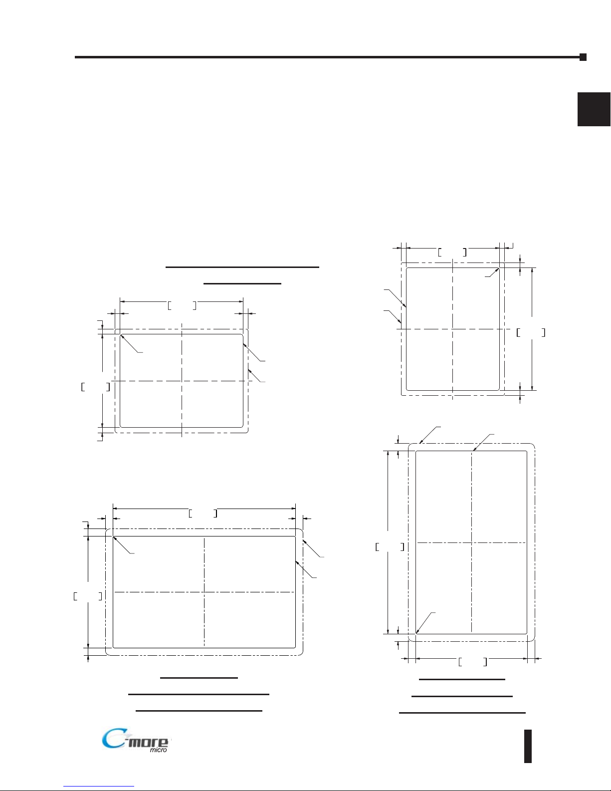
Step 4 – Install C-more 6” Micro-Graphic Panel
The C-more 6” Micro-Graphic panel can be mounted through a cutout in an enclosure by using
the template that is provided with the panel, or using the dimensions shown below. Cutout
dimensions for the 20-button landscape and 21-button portrait keypad bezel options are also
shown below. The keypad bezels also include a template that can be used. The enclosure
mounting thickness range for the panels and the keypad bezels is 0.04”–0.2” [1–5 mm].
The screw torque range for the screws used on the panel mounting clips and the keypad bezel
mounting clips is 21-28 oz-in [0.15-0.2 Nm].
See Chapter 2: Specifications for additional product dimensions.
Chapter 3: Accessories for accessory specifications and dimensions.
0 260
[6 6]
0 256
[6 5]
0 256
[6 5]
0 260
[6 6]
R 118 [R3]
CUTOUT
CUTOUT
OUTLINE
BEZEL
OUTLINE
122 2
+1
0
+0 04
0 00
4 811
161 0
+1
0
+0 04
0 00
6 339
Units Inches [mm]
0 382
[9 7]
0 382
[9 7]
0 382
[9 7]
0 382
[9 7]
143 0
+1
0
+0 04
0 00
5 630
CUTOUT
234 6
+1
0
+0 04
0 00
9 236
R0 59 [R1 5]
CUTOUT
OUTLINE
BEZEL
OUTLINE
EA1-S6ML & EA1-S6MLW
Panel Cutout
BEZEL
OUTLINE
0 382
[9 7]
0 382
[9 7]
0 382
[9 7]
0 382
[9 7]
143 0
+1
0
+0 04
0 00
5 630
CUTOUT
234 6
+1
0
+0 04
0 00
9 236
R0 59 [R1 5]
CUTOUT
OUTLINE
EA-MG6-BZ2
Landscape (Horizontal)
Keypad Bezel Cutout
EA-MG6-BZ2P
Portrait (Vertical)
Keypad Bezel Cutout
0 260
[6 6]
0 256
[6 5]
0 256
[6 5]
0 260
[6 6]
R 118 [R3]
CUTOUT
CUTOUT
OUTLINE
BEZEL
OUTLINE
122 2
+1
0
+0 04
0 00
4 811
161 0
+1
0
+0 04
0 00
6 339
Landscape Mode (Horizontal)
Portrait Mode (Vertical)
EA1-MG6-USER-M Hardware User Manual, 1st Ed. Rev C, 09/10
1–10
Chapter 1: Getting Started
1
®
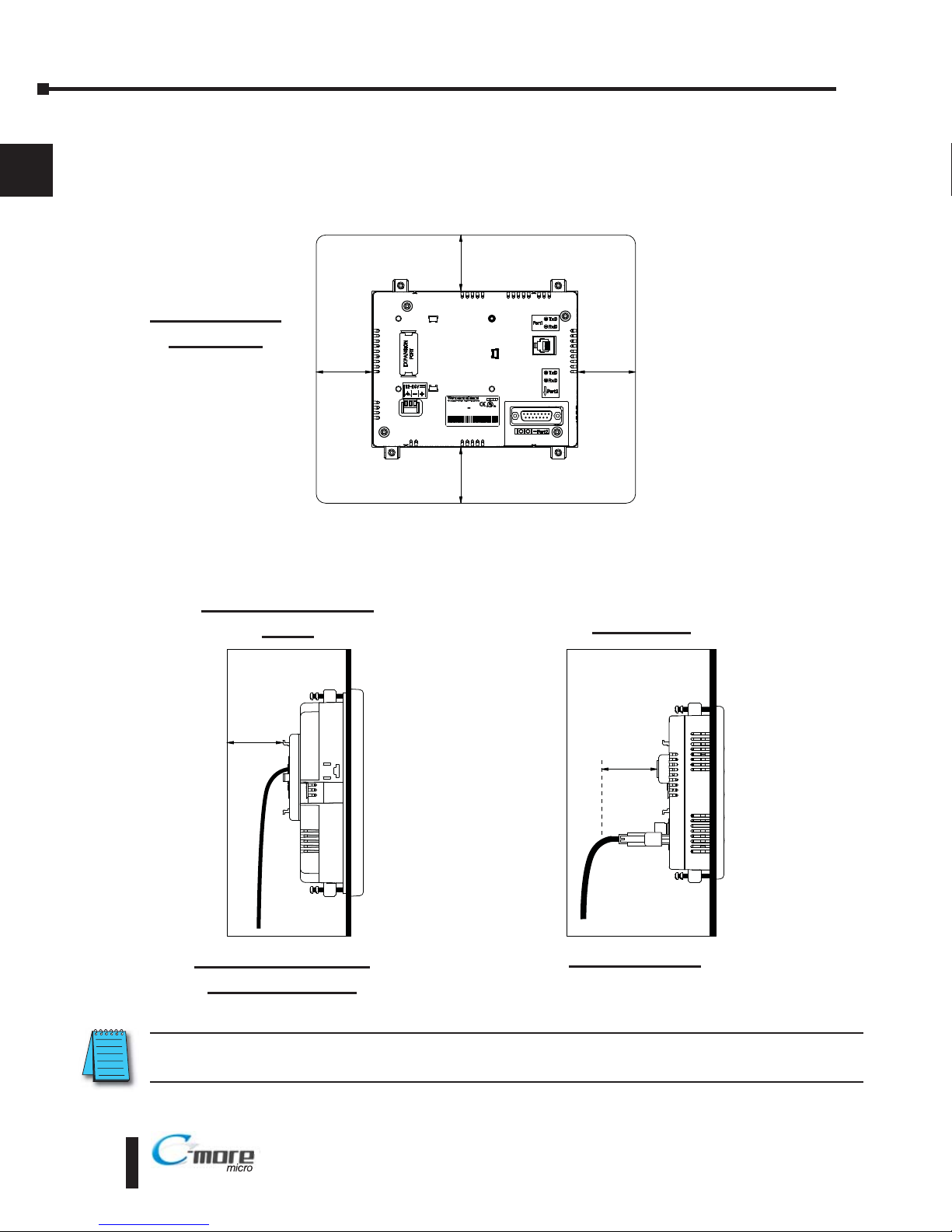
Enclosure Clearances
A 1.2” [30mm] minimum clearance is required inside an enclosure for proper ventilation of
the C-more Micro-Graphic panel.
1.2
[30.0]
1.2
[30.0]
Enclosure Enclosure
8 1
15
9
I T D
I T D
M 7
M 7
D te o e * **
D te o e* **
R01
R01
MAD IN HI A
MAD IN HI A
E 1 S6M W + se a num er
E 1 S6M W + se a num er
MODE : A1 S6M
MODE : A1 S6M W
N UT 12- 4V 6 5W
N UT 12- 4V 6 5W
NDC NT Q.
NDC NT Q.
1.2
[30.0]
1.2
[30.0]
1.2
[30.0]
1.2
[30.0]
Enclosure
units: inches [mm]
EA1-S6ML(W) with
EA-MG6-BZ2(P)
EA1-S6ML(W)
NOTE: Additional clearance inside the enclosure is required when connecting to the 15-pin serial
communications port (Port2).
EA1-S6ML(W)
Rear View
Panel with Keypad
Bezel
Panel only
EA1-MG6-USER-M Hardware User Manual, 1st Ed. Rev C, 09/10
1–11
Chapter 1: Getting Started
1
®
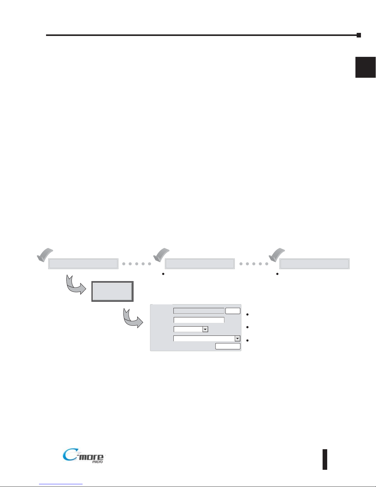
Step 5 – Install the Programming Software and Develop a Project
Following are the minimum system requirements for running C-more Micro-Graphic
Programming Software, EA-MG-PGMSW, on a PC:
• Personal Computer with a 333 MHz or higher processor (CPU) clock speed recommended;
(Windows® 2000 with Service Pack 4 or Windows® XP, 800 MHz or higher processor (CPU)
clock speed recommended (Windows® Vista (32 bit)); Intel® Pentium/Celeron family, or AMD®
K6/Athlon/Duron family, or compatible processor recommended
• Keyboard and Mouse or compatible pointing device
• Super VGA color video adapter and monitor with at least 800 x 600 pixels resolution
(1024 x 768 pixels recommended) 64K color minimum
• 150 MB free hard-disk space
• 128 MB free RAM (512 MB recommended); 512 MB free RAM (1GB recommended) for Vista
• CD-ROM or DVD drive for installing software from the CD, or internet access to download free
programming software
• USB port to use with an EA-MG-PGM-CBL, USB to RS232 Programming Cable Assembly for
project transfer from the programming software to the panel
• Operating System - Windows® XP Home / Professional Edition Service Pack 2, Windows® 2000
with Service Pack 4, or Windows® Vista (32 bit)
Insert the supplied CD-ROM into the PC’s CD-ROM drive and follow the instructions. If you
need assistance during the software installation, please refer to the supplied Software Installation
Guide or call the AutomationDirect Technical Support team at 770-844-4200.
Start a Project
Simulate Project
Send Project to panel
Allows you to check the operation of
your project before downloading it to
the panel.
Download your project to the
connected panel.
Enter a name
for your project
Make a New Project
PLC Protocol
DirectLogic K Sequence
HMI Type
Project
Location
EA1 S6ML
MyProject
C \My Documents\C more Projects\
Select Project
Protocol Setup
Browse
Select the C-more
Micro-Graphic panel
Select the PLC Driver

EA1-MG6-USER-M Hardware User Manual, 1st Ed. Rev C, 09/10
Chapter 1: Getting Started
1
®
1–12
Step 6 – Connect C-more 6” Micro-Graphic Panel to Computer
NOTE: Install C-more Micro-Graphic Programming software before connecting the panel to the PC to ensure
the panel drivers install correctly.
Use an EA-MG-PGM-CBL, USB to RS-232 Programming Cable Assembly, from an USB
port type A on the project development PC, through the supplied converter, to the RJ12 RS232 programming/PLC serial communications port on the C-more Micro-Graphic panel as
shown below.
C-more 6 inch
Micro Graphic
Panel
USB
Cable
User PC
Serial
Cable
PC to Panel Programming
Cable Assembly
(Includes serial & USB cables)
EA MG PGM CBL
USB to RS232
Converter
USB to RS-232 Programming Cable Assembly
NOTE: When the panel is powered through Port1 from a connected PLC or PC, the screen brightness is
diminished because the panel is running in Low-Power Mode. For full brightness, connect an external
12-24 VDC power source to the panel’s power connection. Low-Power Mode is intended for initial
programming. For full brightness, connect an external 12-24 VDC power source when the panel is installed
in its application.
EA1-MG6-USER-M Hardware User Manual, 1st Ed. Rev C, 09/10
1–13
Chapter 1: Getting Started
1
®
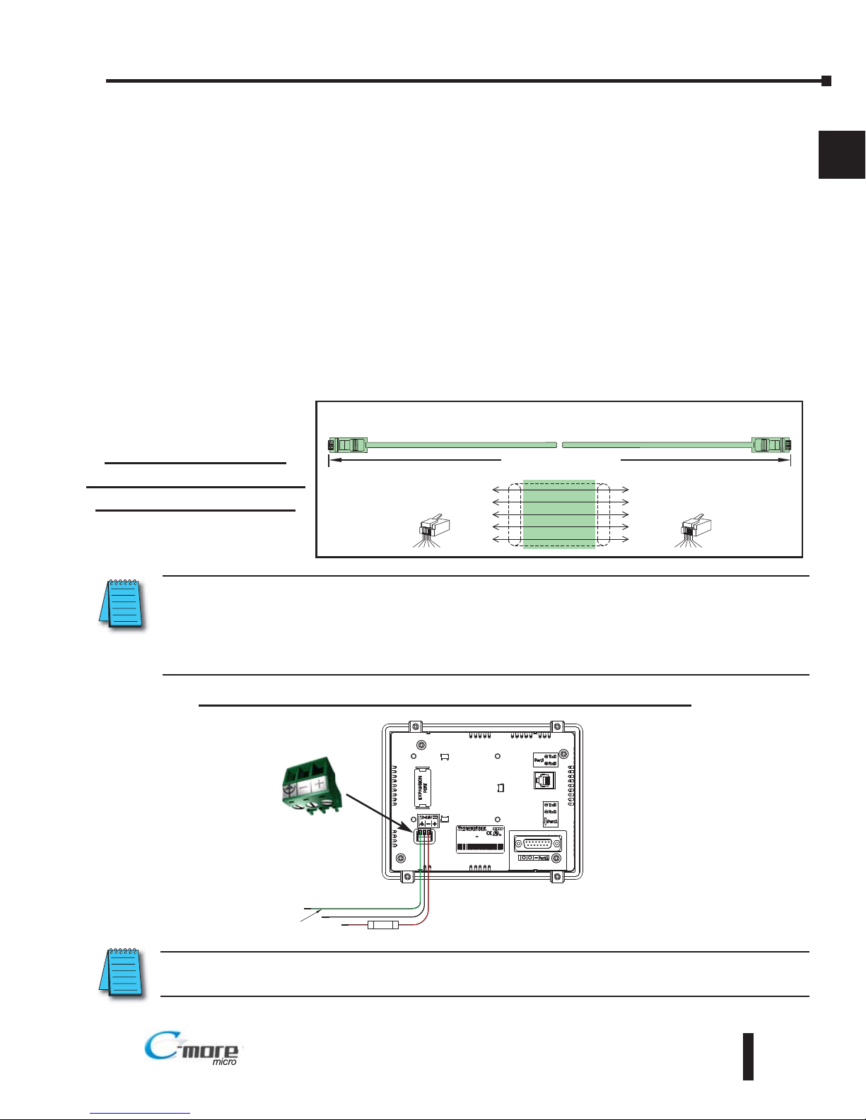
Step 7 – Providing Power to the C-more 6” Micro-Graphic Panel
Power can be supplied to the C-more Micro-Graphic panel in one of three different ways.
1.) During operation, the panel functions in High-Power Mode when powered by a minimum 1 Amp
12 - 24 VDC power source. Recommended power supplies are AutomationDirect part number
PSP24-024S or PSP24-024C.
2.) The C-more Micro-Graphic panel is powered during programming from the PC through the USB
to RS-232 Programming Cable Assembly, EA-MG-PGM-CBL. The panel will operate in Lowpower mode when powered by the PC and result in a dim screen.
3.) Optionally, the C-more Micro-Graphic panel can function in Low-Power Mode powered from most
AutomationDirect PLC’s RJ12 serial communications port. Use a DV-1000CBL communications
cable, or a DV-1000CBL communications cable with a FA-15HD 15-pin HD DSub/RJ12 Adapter
connected to most AutomationDirect PLC’s 15-pin HD communications port (DL06, D2-250-1
& D2-260) PLCs for Low-Power operation. See Chapter 6: PLC Communications for additional
details. The panel will operate in low-power mode when powered by the PC.
Power Supplied to Panel through Cable from CLICK and Direct Logic PLC RJ12 port:
DL05, DL105, DL205, DL350, DL450, H2-WINPLC
RS-232C (p/n DV-1000CBL)
To PLC
RJ12 Port
To C more
Micro Graphic
Serial Port1
6
4
GND
TXD
1
3
GND
Wiring Diagram
3
RXD
2
+5 V
1 Sig GND
2 not used
3 RXD
4 TXD
5 +5 VDC
6 Sig GND
1 2 3 4 5 6
RJ12 6 pin
Phone Plug
(6P6C)
1
GND
6
GND
1 2 3 4 5 6
RJ12 6 pin
Phone Plug
(6P6C)
1 S g GND
2 +5 VDC
3 RXD
4 TXD
5 not used
6 S g GND
4
5
RXD
TXD
+5 V
10 feet [3.0 m] Maximum
L T D
L T D
M17
M17
ae od :
ae od :
R 1
R 1
ADE N CH NA
ADE N CH NA
EA - 6M W + e al umb r
EA - 6M W + e al umb r
MODEL A S6MLW
MODEL A S6MLW
NPUT:122 V . W
NPUT:122 V . W
I DCO T Q.
I DCO T Q.
81
15
9
Supply to Panel
1 A @ 12 24 VDC
(10 8 26 4 VDC)
+
–
GND
Equipment
Ground
Recommended
DC Supply Fuse
750 mA fast acting,
ADC p/n AGC 75
*Panel Powered from
AutomationDirect PLC via
Communications Cable
Panel Powered from a DC Power Source - Wiring Diagram
NOTE: Recommended DC power supply to power the C-more Micro Graphic Panel, AutomationDirect Part No.
PSP24-024S or PSP24-024C.
NOTE: When the 6” panel is powered through Port1 from a connected PLC or PC, the screen brightness is
diminished because the panel is running in Low-Power Mode. For full brightness, connect an external
12-24 VDC power source to the panel’s power connection. Low-Power Mode is intended for initial
programming. For full brightness, connect an external 12-24 VDC power source when the panel is installed
in its application.
EA1-MG6-USER-M Hardware User Manual, 1st Ed. Rev C, 09/10
1–14
Chapter 1: Getting Started
1
®
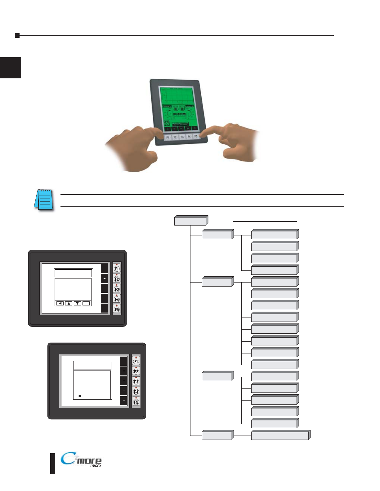
Step 8 – Accessing the C-more 6” Micro-Graphic Panel Setup Screens
To access the Setup Menu of the panel’s setup screens, press the the BAK [F1] and ENT [F5]
function keys simultaneously for three (3) seconds.
From the Setup Menu, information about the panel can be obtained, settings can be adjusted,
and panel functions can be tested.
NOTE: See Chapter 5: System Setup Screens for details on using the setup screen settings and functions.
BAK
1 Information >
2 Setting >
3 Test Menu >
4 Exit >
UP
DWN
ENT
ENT
SETUP MENU
BAK
Total
1835008 Bytes
Usage
26206 Bytes
Free
1808802 Bytes
MEMORY
Setup Menu
[pg 5 5]
1 Information
[pg 5 6]
1 Memory
[pg 5 6]
2 Setting
[pg 5 7]
1 LCD Contrast
[pg 5 7]
2 Backlight
[pg 5 8]
3 Beep
[pg 5 10]
4 Calibration
[pg 5 11]
5 Clear User Memory
[pg 5 12]
1 Serial Port1 Loop Back Test
[pg 5 15]
2
Ser al Port2 Loop Back Tes
t
[pg 5 16]
3 PLC Enquiry Test
[pg 5 17]
Do you want to exit from System Screen?
No[F1] / Yes[F5]
3 Test Menu
[pg 5 15]
4 Exit
[pg 5 18]
2 Protocol
[pg 5 6]
3 Extens ons
[pg 5 6]
4 Versions
[pg 5 6]
6 Reset to Factory Default
[pg 5 12]
7 Hourglass
[pg 5 13]
8 Rotation
[pg 5 14]
4 Buzzer Test
[pg 5 17]
5 Touch Panel Test
[pg 5 18]
Menu Flow Chart
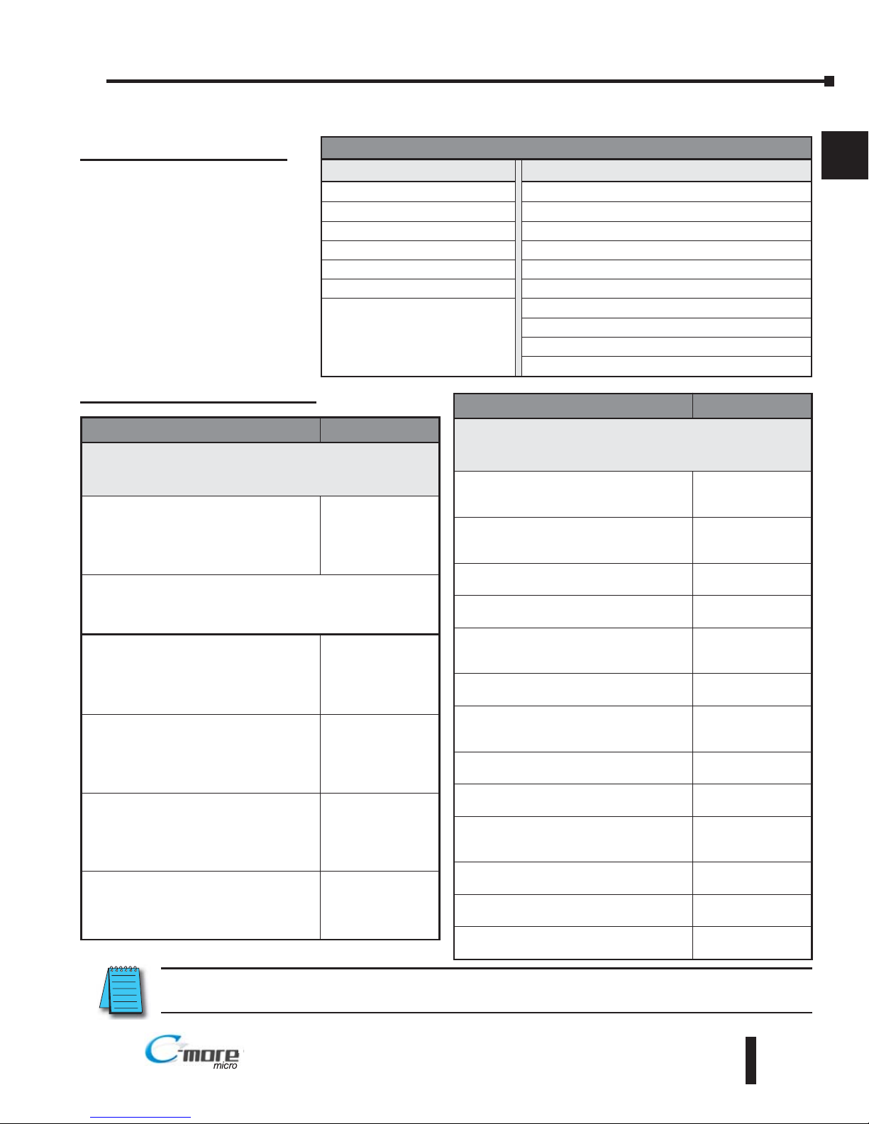
Step 9 – Choose C-more 6” Micro-Graphic Panel to PLC Protocol & Cables
Cable Description Cable Part No.
Cables used with serial Port1
AutomationDirect CLICK,
Direct
LOGIC
PLC RJ-12 port, DL05, DL06, DL105,
DL205, D3-350, D4-450 & H2-WinPLC
(RS-232C)
DV-1000CBL
Note: The PLC can provide 5 VDC through this cable. No
external 12-24 VDC souce is required, however,
screen brightness is diminished and the alarm beep
will not function.
Direct
LOGIC DL405 PLC 15-pin D-sub
port, DL405
(RS-232C)
D4-1000CBL
Direct
LOGIC (VGA Style) 15-pin port,
DL06, D2-250 (250-1), D2-260
(RS-232C)
Use with DV-1000CBL cable.
FA-15HD
Direct
LOGIC PLC 15-pin D-sub port,
DL405
(RS-232C).
FA-CABKIT
Direct
LOGIC PLC RJ-11 port, D3-340
(RS-232C).
OP-3CBL-1
EA1-MG6-USER-M Hardware User Manual, 1st Ed. Rev C, 09/10
1–15
Chapter 1: Getting Started
1
®
NOTE: See Chapter 6: PLC Communications for a detailed chart of PLC compatibility & cable connections.
Chapter 6 includes wiring diagrams for end user construction of certain cables.
Available purchased cables
Cable Description Cable Part No.
Cables used with serial Port2
AutomationDirect CLICK,
Direct
LOGIC PLC
RJ-12 port, DL05, DL06, DL105, DL205,
D3-350, D4-450 & H2-WinPLC (RS-232C)
EA-2CBL
Direct
LOGIC (VGA Style) 15-pin port,
DL06, D2-250 (250-1), D2-260
(RS-232C).
EA-2CBL-1
Direct
LOGIC PLC RJ-11 port, D3-340
(RS-232C).
EA-3CBL
Direct
LOGIC DL405 PLC 15-pin D-sub
port, DL405 (RS-232C).
EA-4CBL-1
Direct
LOGIC PLC 25-pin D-sub port,
DL405, D3-350, DL305 DCU and all DCM’s
(RS-232C).
EA-4CBL-2
Allen-Bradley MicroLogix 1000, 1100,
1200 & 1500 (RS-232C)
EA-MLOGIX-CBL
Allen-Bradley SLC 5-03/04/05,
ControlLogix, CompactLogix, FlexLogix
DF1 port (RS-232C)
EA-SLC-232-CBL
Allen-Bradley PLC-5 DF1 port
(RS-232C)
EA-PLC5-232-CBL
Allen-Bradley MicroLogix, SLC 5-01/02/03,
PLC5 DH485 port (RS-232C)
EA-DH485-CBL
GE 90/30, 90/70, Micro 90, Versamax
Micro (Port2) 15-pin D-sub port
(RS-422A)
EA-90-30-CBL
MITSUBISHI FX Series 25-pin port
(RS-422A)
EA-MITSU-CBL
MITSUBISHI FX Series 8-pin mini-DIN
(RS-422A)
EA-MITSU-CBL-1
OMRON Host Link (C200 Adapter, C500)
(RS-232C)
EA-OMRON-CBL
PLC Drivers
Serial - port1 or port2 Serial - port2 only
AutomationDirect CLICK Allen-Bradley DF1 Half Duplex
AutomationDirect K-sequence Allen-Bradley DF1 Full Duplex
AutomationDirect DirectNET Allen-Bradley PLC5 DF1
AutomationDirect Modbus Allen-Bradley DH485
Modicon Modbus RTU GE SNPX (90/30, 90/70, Micro 90, VersaMax Micro)
Entivity Modbus RTU Mitsubishi FX
Mitsubishi Q & QnA
Omron Host Link (C200 Adapter, C500)
Omron FINS Serial (CJ1, CS1)
Siemens PPI (S7-200 CPU)
Available PLC Protocols
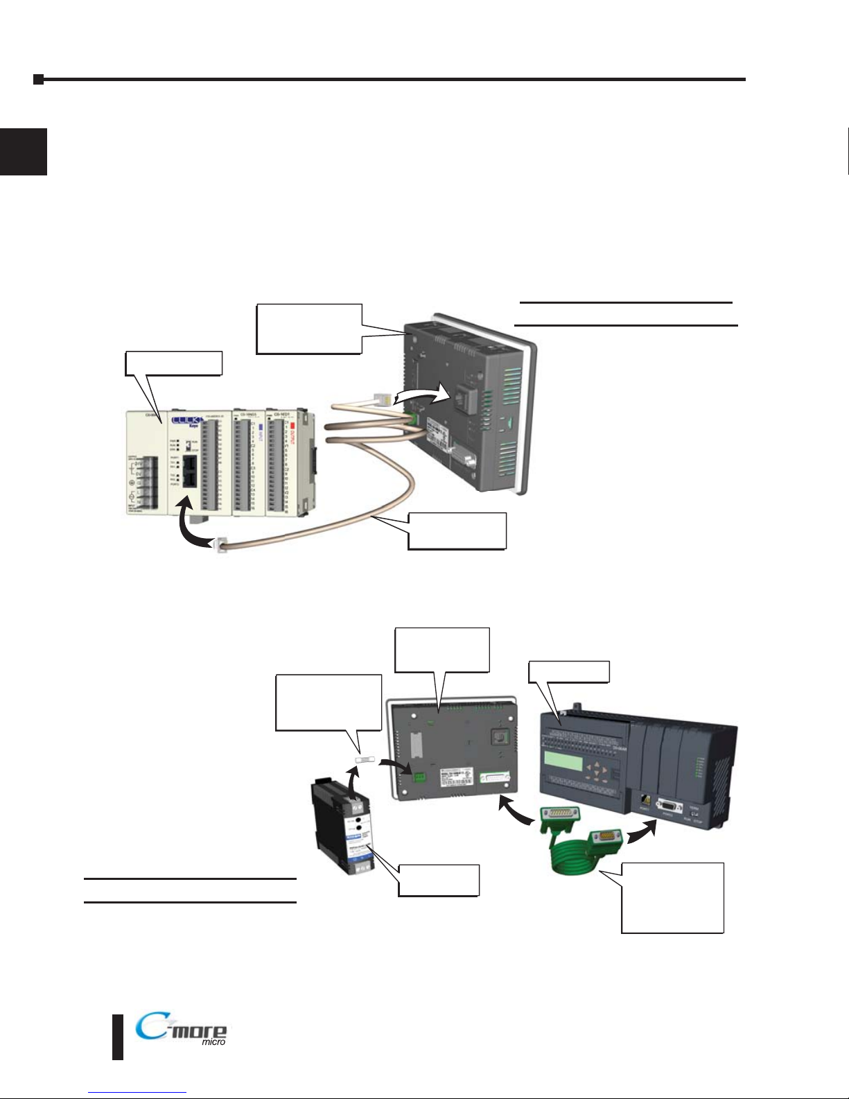
Step 10 – Connect C-more 6” Micro-Graphic Panel to PLC
Connect the serial communications cable between the C-more Micro-Graphic panel and the
PLC. The panel can be connected to the PLC via the panel’s built-in RJ12 serial
communications port (RS-232) or 15-pin serial communications port with either RS-232, RS422 or RS-485 communications.
EA1-MG6-USER-M Hardware User Manual, 1st Ed. Rev C, 09/10
1–16
Chapter 1: Getting Started
1
®
Port 1
Port 2
DV 1000CBL
serial cable
CLICK PLC
C-more 6 Inch
Micro-Graphic
Panel
Port
2
Port
2
C-more to
Direct LOGIC
VGA 15 pin port
serial cable
p/n EA 2CBL 1
DL-06 PLC
PSP-24-024S
Power Supply
Recommended
DC Supply Fuse
750 mA fast acting,
ADC p/n AGC-75
C-more 6 Inch
Micro-Graphic
Panel
Example of panel’s Port 1
connected to a CLICK PLC
Example of panel’s Port 2
connected to a DL06 PLC
 Loading...