

Page 1

Chapter
Chapter
Chapter
GettinG Started
1
1
1
In This Chapter...
Introduction ...................................................................................................................1-2
The Purpose of This Manual �����������������������������������������������������������������������������������������1-2
Supplemental Manuals �������������������������������������������������������������������������������������������������1-2
Technical Support ��������������������������������������������������������������������������������������������������������1-2
Conventions Used ..........................................................................................................1-3
Key Topics for Each Chapter �����������������������������������������������������������������������������������������1-3
Product Overview ..........................................................................................................1-4
Quick Start Steps ...........................................................................................................1-5
Step 1 – Unpack and Inspect ����������������������������������������������������������������������������������������1-5
Step 2 – Install Optional Hardware Accessories �������������������������������������������������������������1-6
Step 3 – Become Familiar with Available Communication Ports ������������������������������������1-7
Step 4 – Install the Programming Software and Develop a Project �������������������������������1-8
Step 5 – Connect HMI to Computer ����������������������������������������������������������������������������1-9
Step 6 – Provide Power to the HMI ����������������������������������������������������������������������������1-10
Step 7 – Access the EA9-RHMI Setup Screens �������������������������������������������������������������1-13
Step 8 – Choose HMI to Device Cable������������������������������������������������������������������������1-14
Step 9 – Connect HMI to PLC ������������������������������������������������������������������������������������1-17
Page 2

Chapter 1 - Getting Started
Introduction
1
2
3
4
5
6
7
8
9
10
11
12
13
14
The Purpose of This Manual
Thank you for purchasing our C-more® human-machine interface (HMI) family of products.
This manual describes AutomationDirect.com’s C-more headless HMI, its specifications,
included components and available accessories and provides you with important information
for installation, connectivity and setup. The manual shows you how to install, wire and use
the product. It also helps you understand how to interface the HMI to other devices in a
control system.
This user manual contains important information for personnel who will install the HMI
and accessories and for the personnel who will be programming the HMI. If you understand
control systems that make use of operating interfaces such as the C-more RHMI, our user
manuals will provide all the information you need to get and keep your system up and
running.
Supplemental Manuals
If you are familiar with industrial control type devices, you may be able to get up and running
with just the aide of the Quick Start Guide that is included with each HMI. You should also
refer to the On-line help that is available in the C-more programming software for more
information about programming the panel.
Technical Support
We strive to make our manuals the best in the industry. We rely on your feedback to let
us know if we are reaching our goal. If you cannot find the solution to your particular
application, or, if for any reason you need technical assistance, please call us at:
770–844–4200
Our technical support group will work with you to answer your questions. They are available
Monday through Friday from 9:00 A.M. to 6:00 P.M. Eastern Time. We also encourage you
to visit our web site where you can find technical and non-technical information about our
products and our company.
http://c-more.automationdirect.com
A
B
C
D
1-2
®
EA9-RHMI-USER-M Hardware User Manual, 1st Ed. Rev. G
Page 3
Conventions Used
Chapter 1 - Getting Started
1
When you see the “notepad” icon in the left-hand margin, the paragraph to its immediate right will be a special note.
The word NOTE: in boldface will mark the beginning of the text.
When you see the “exclamation mark” icon in the left-hand margin, the paragraph to its immediate
right will be a warning. This information could prevent injury, loss of property, or even death (in
extreme cases). The word Warning: will mark the beginning of the text.
Key Topics for Each Chapter
The beginning of each chapter will list the key topics
that can be found in that chapter.
Getting Started
In This Chapter...
General Information
.................................................................1-2
...........................................................................1-4Specifications
CHAPTER
2
3
4
5
6
7
8
9
1
10
11
12
EA9-RHMI-USER-M Hardware User Manual, 1st Ed. Rev. G
13
14
A
B
C
D
®
1-3
Page 4

Chapter 1 - Getting Started
Product Overview
1
2
3
4
5
6
7
8
9
10
11
12
13
Some of the features designed into the product to provide excellent hardware and software are
listed below.
• Drivers for ELO Single Touch Resistive/SAW, EETI eGalax Single Touch Resistive and singletouch Protected Capacitive touch screens that can be used with many touch capable industrial touch
monitors
• Plenty of memory and methods to get data in/out of the panel
• Overlapping active devices on the screen
• 65,536 colors for enhanced graphics
• HDMI Video Output supporting several resolutions including 720p (60Hz) and Audio
• Built-in FTP client/server, E-mail client, and Web server
• User configurable LED on the front of the unit
• Built-in project simulation; test on PC while developing
• Ethernet 10/100 Base-T communications
• 15-pin serial port with RS-232, RS422/485
• 3-wire terminal block RS-485 port
• Programming via USB or Ethernet
• Animation of bitmaps and objects
• Thousands of built-in symbols and Windows fonts
• PID face plate, trending, alarming and a recipe database
• Trend Data Logging
• Event Manager to trigger actions based on assigned state changes, schedules, PLC tag names, etc. set
up in a database environment. The event can also trigger a sound byte, initiate a screen capture, send
a data file (FTP), send an E-mail, etc.
• Internet Remote Access
14
A
B
C
D
1-4
®
EA9-RHMI-USER-M Hardware User Manual, 1st Ed. Rev. G
Page 5
Quick Start Steps
Chapter 1 - Getting Started
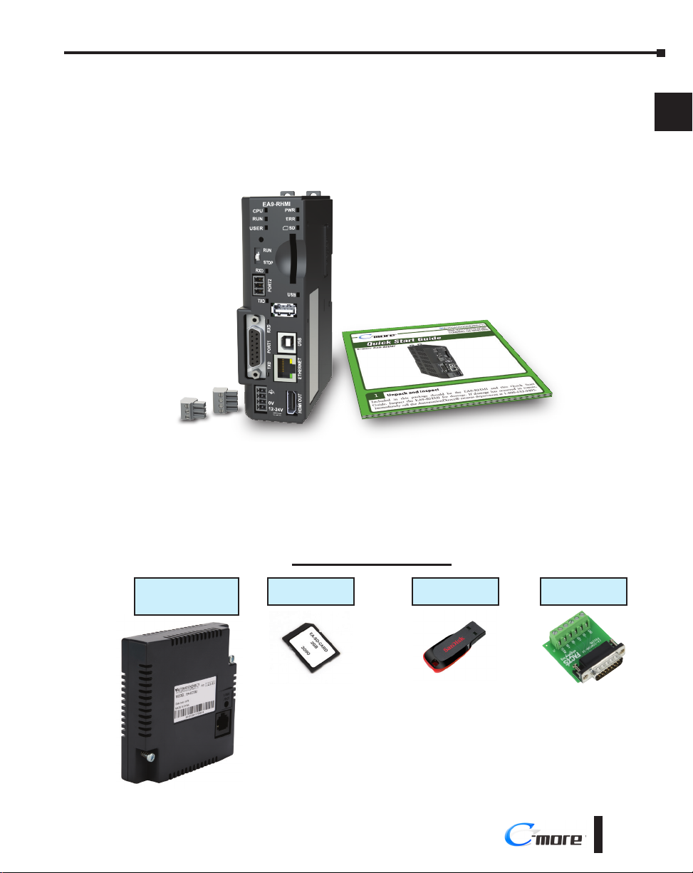
Step 1 – Unpack and Inspect
a.) Unpack the C-more RHMI from its shipping carton. A Quick Start Guide is included in
the carton.
b.) Unpack any accessories that have been ordered, such as programming cable,
communications cable, etc.
c.) Inspect all equipment for completeness. If anything is missing or damaged, immediately
call the AutomationDirect® returns department @ 1-800-633-0405.
Optional Accessories
1
2
3
4
5
6
7
8
9
10
11
12
Communication
Expansion Module
EA-ECOM
EA9-RHMI-USER-M Hardware User Manual, 1st Ed. Rev. G
SD Memory Card
EA-SD-CARD
USB Pen Drive
USB-FLASH
DSUB Port Adapter
EA-COMCON-3A
®
13
14
A
B
C
D
1-5
Page 6
Chapter 1 - Getting Started
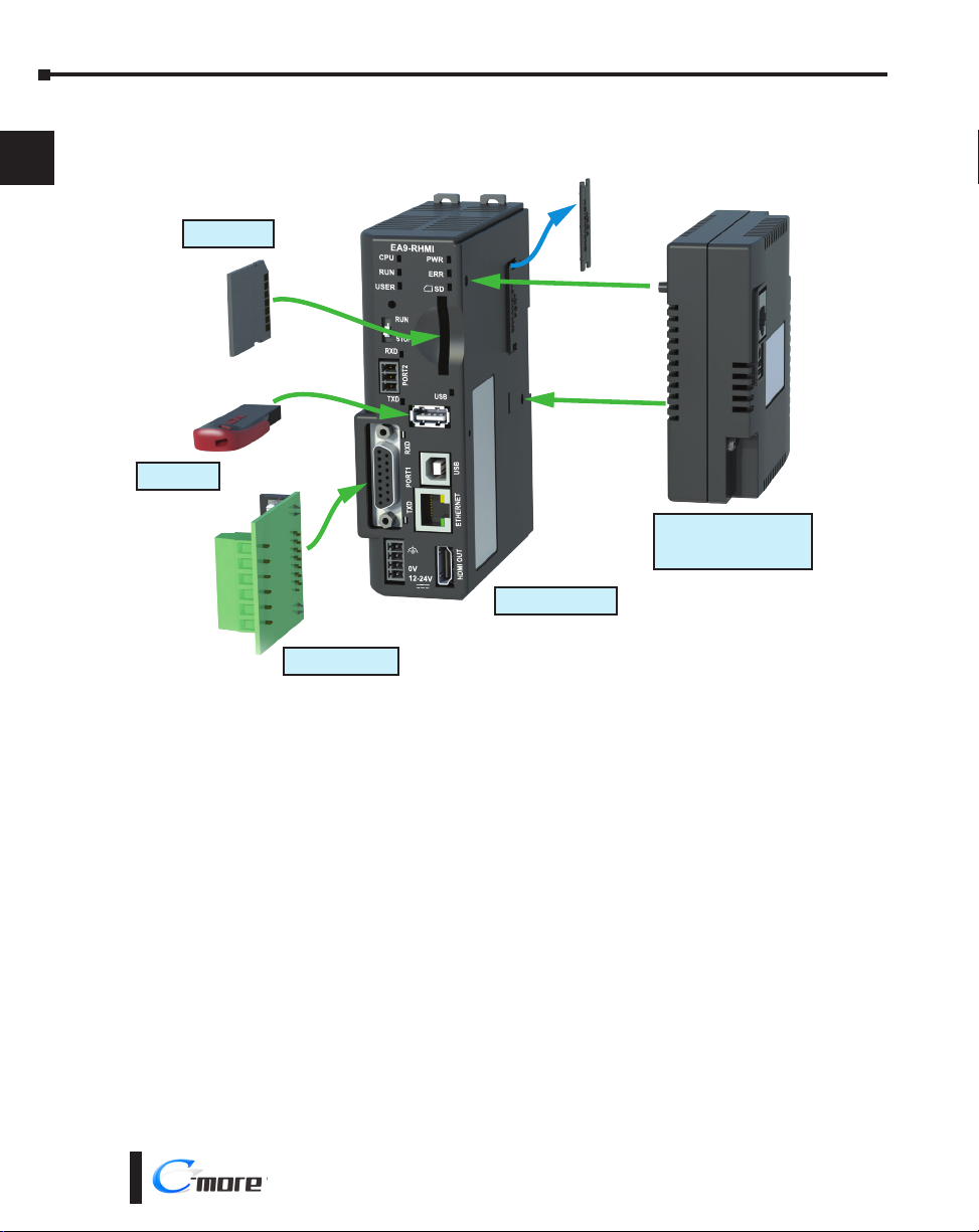
Step 2 – Install Optional Hardware Accessories
1
2
3
4
5
6
7
8
9
10
11
12
EA-SD-CARD
USB-FLASH
EA-ECOM
Ethernet Communication
Module
C-more EA9-RHMI
EA-COMCON-3A
13
14
A
B
C
D
1-6
®
EA9-RHMI-USER-M Hardware User Manual, 1st Ed. Rev. G
Page 7

Chapter 1 - Getting Started
Step 3 – Become Familiar with Available Communication Ports
Pin Signal
1 Frame GND
TXD (232C)
2
RXD (232C)
3
N.C.
4
5 Logic GND
Port 2
Serial Communication
RS-485
Logic Ground
–
+
EA9-3TB
Port 1
PLC Serial Communications
RS-232C / RS-422 / RS-485
8 1
15 9
Pin Signal Pin Signal
6 LE (for DH485)
CTS (232C)
7
RTS (232C)
8
RXD+ (422/485)
9
10 RXD– (422/485)
11 TXD+ (422/485)
TXD– (422/485)
12
Term. Resistor
13
N.C.
14
15 N.C.
HDMI Port Video Out
SD Card Slot
Expansion Port
(Right Side)
USB Port - Type A
USB Device Options
Pin Signal
4
1 Vbus
3
21
Ethernet 10/100 Base-T
PLC Communications,
Programming/Download
Pin Signal
1 TD+
2
3
4
2
3
4
USB Port - Type B
Programming
Pin Signal
1 N.C.
2
3
4
TD–
RD+
do not use
D–
D+
GND
ShieldSHELL
D–
D+
GND
ShieldShell
Pin Signal
2
3
1 8
5 Do not use
RD–
6
N.C.
7
N.C.
8
1
2
3
4
5
6
7
1
4
8
9
10
11
12
NOTE: See Chapter 6: PLC Communications for additional details on the available communication ports, protocols
and cables.
EA9-RHMI-USER-M Hardware User Manual, 1st Ed. Rev. G
®
13
14
A
B
C
D
1-7
Page 8

Chapter 1 - Getting Started
Step 4 – Install the Programming Software and Develop a Project
1
2
3
4
5
6
7
8
9
10
11
Download the latest version of the C-more Programming Software, p/n EA9-PGMSW,
from the Automationdirect website. Alternately, if the C-more Programming Software CD is
available, you may install from the software CD. Refer to the AutomationDirect website for
current minimum system requirements for installation.
For software download installation, follow the screen prompts to download and install the
C-more Programming Software.
For CD installation, insert the supplied CD into the PC’s CD drive and navigate to the CD
drive location on the PC. Double-click on EA_Setup.exe and follow the instructions. If you
need assistance during the software installation, call the AutomationDirect Technical Support
team @ 770-844-4200.
NOTES: Regarding Ethernet access to a C-more panel.
If you intend to take advantage of the methods of remote access to the panel, including the web server, PC remote
access, FTP, iOS or Android app, you need to consider the security exposure in order to minimize the risks to your
process and your C-more panel.
Security measures may include password protection, changing the ports exposed on your network, including a VPN
in your network, and other methods. Security should always be carefully evaluated for each installation. Refer to
Appendix C - Security Considerations for Control Systems Networks.
12
13
14
A
B
C
D
1-8
®
EA9-RHMI-USER-M Hardware User Manual, 1st Ed. Rev. G
Page 9

Step 5 – Connect HMI to Computer
• Connect a USB Programming Cable, such as p/n USB-CBL-AB15, from a USB type A port on the
PC to the USB type B programming port on the C-more HMI.
• Or connect the C-more EA9-RHMI and PC together either directly or via an Ethernet switch and
CAT5 Ethernet cables
PC
Chapter 1 - Getting Started
C-more
EA9-RHMI
1
2
3
PC
PC
USB
Port
Stride™
Ethernet Switch
10/100 Base-T
(such as SE2-SW5U)
Ethernet
Port
Ethernet
Port
USB-CBL-ABxx
USB Cable
Ethernet CAT5
Cable
Ethernet CAT5
Cable
USB
Port
C-more
EA9-RHMI
Auto MDI / MDI-X
Ethernet Port
C-more
EA9-RHMI
4
5
6
7
8
9
10
11
12
13
14
A
Auto MDI / MDI-X
Ethernet Port
EA9-RHMI-USER-M Hardware User Manual, 1st Ed. Rev. G
B
C
D
®
1-9
Page 10

Chapter 1 - Getting Started
Step 6 – Provide Power to the HMI
• Connect a dedicated 12-24 VDC Class 2 power supply to the DC connector on the front of the
1
2
3
C-more EA9-RHMI. Make sure to connect the ground terminal to a proper equipment ground.
• Then turn on the power source and check the LED status indicators on the front of the C-more
EA9-RHMI for proper indication (see next page).
NOTE: A dedicated power supply is recommended. If the power supply also feeds inductive loads such as
solenoids or relays, the transients caused by these loads can affect the operation of or cause damage to HMI
components.
4
5
6
7
8
9
10
11
12
13
14
A
DC Power Wiring
Recommended Fuse
Rating ADC part number
2.5 A MDL2-5
Equipment
Ground
0V
12- 24 VDC
Tightening Torque
Power supply cable torque 32-35 oz-in (0.22-0.25 Nm)
Warning: Use 60/75 °C copper conductors only.
C0-4TB
Terminal Block
B
C
D
1-10
®
EA9-RHMI-USER-M Hardware User Manual, 1st Ed. Rev. G
Page 11

Step 6 – Provide Power to the HMI (cont’d)
C-more LED Status Indicators
System Status LEDs
- CPU Green/Red/Orange
- RUN Green/Red/Orange
- USER Green/Red/Orange
Reset Button
Chapter 1 - Getting Started
System Status LEDs
- PWR Green
- ERR Red
SD Status Green
1
2
3
RUN / STOP Switch
Receive Green
Port 2 Serial Port
Transmit Green
Receive Green
Port 1 Serial Port
Transmit Green
System Status LEDs
State
LED
Status Loading OS
CPU Running Normal
Project Loaded and Running
No User Project
Password Required
Errors Power Loss Detection
Memory Error
OS Error
Watch Dog Time Out
No Log Storage Found
General Error*
Warning*
Mode Recovery Mode
Safe Mode
*Note - See Chapter 8 - Troubleshooting for General Error and Warning explanations.
CPU RUN ERR
Blinking Green (0.5s) OFF OFF
Green – OFF
– Green –
– Orange –
– Blinking Orange (0.5s) Blinking Red (0.5s)
Blinking Orange (0.2s) – –
Red OFF Red
Blinking Orange (0.5s) OFF Red
Blinking Red (0.5s) – Red
– Blinking Orange (0.5s) Blinking Red (0.5s)
– Red (0.5s) Blinking Red (0.5s)
– Blinking Orange (0.5s) Blinking Red (0.5s)
Blinking Orange (0.5s) OFF OFF
Orange OFF Red
USB Status Green
4
5
6
7
8
9
10
11
12
13
14
A
B
C
D
EA9-RHMI-USER-M Hardware User Manual, 1st Ed. Rev. G
®
1-11
Page 12

Chapter 1 - Getting Started
EA9-RHMI Beep
1
2
3
4
5
6
Function Beep Pattern
Boot 1-long, 2-short
Boot Error* 3-long
HDMI Connected 3-short
Reset to Factory Defaults 14 short beeps progressively closer together followed by 1-long beep.
Blink Screen 5-long
*Boot Errors
Multiple Projects
Write Protected SD Card
No Log Storage Found
System Screen (RUN/STOP switch in STOP position)
Password Protected
Beep Functions
7
8
9
10
11
12
13
14
A
B
C
D
Reset Button
Reset Button
Push Action Behavior Note
Push for <15 seconds Reboot the EA9-RHMI
Push for >15 seconds Reset to factory default The project is cleared and all settings are initialized.
While holding down the
reset button, power on the
EA9-RHMI and continue
holding the button for
>15 seconds
RUN / STOP switch
Position Behavior Note
RUN
STOP
Power on the EA9-RHMI
while in the STOP position
System recovery mode
RUN / STOP Switch
Project will run if present and the
RUN LED will be green
The project and any logging
stops and the System Screen is
displayed.
The System Screen is displayed A System Screen password is ignored.
The CPU LED will blink ORANGE. See “No System
Found” in Chapter 8 - Troubleshooting
If no project is loaded in the HMI, the
message “No User Program” will be displayed
on a connected display. The RUN LED will be
orange.
If a password has been set up for the System
Screen, the RUN LED will blink orange.
User Defined LED
The user defined LED on the EA9-RHMI can be controlled from the project to illuminate
red, green or orange. It can also be configured to blink these colors. Refer to the online help
file provided with the programming software for details.
1-12
®
EA9-RHMI-USER-M Hardware User Manual, 1st Ed. Rev. G
Page 13

Step 7 – Access the EA9-RHMI Setup Screens
• Access the Main Menu of the EA9-RHMI System Setup Screens by changing the selector switch on
the front of the unit to STOP.
• Adjust the time and date for the panel by pressing the Setting button on the Main Menu. Then
press the Adjust Clock button on the Setting screen.
• Use the right-pointing arrows for the time or date display to select the unit to change. Use the up
and down arrows to increment or decrement the value for the selected unit.
• Press OK when done to accept the changes to the time and date in the HMI or press Cancel to exit
the Adjust Clock setup screen without making any changes.
• Press the Main Menu button on the Setting screen and then the Exit button on the Main Menu
screen to return to the application screen.
• Change the selector switch on the front of the unit to RUN.
Chapter 1 - Getting Started
1
2
3
4
5
6
7
8
9
NOTE: For more information on EA9-RHMI setup screens, see Chapter 5 - System Setup Screens.
EA9-RHMI-USER-M Hardware User Manual, 1st Ed. Rev. G
®
10
11
12
13
14
A
B
C
D
1-13
Page 14

Chapter 1 - Getting Started
Step 8 – Choose HMI to Device Cable
The table below shows the PLCs, controllers and protocols supported by the EA9-RHMI.
1
2
Model Protocols
Ensure your controller and protocol are supported.
3
4
5
6
7
8
9
10
AutomationDirect
11
12
13
14
A
B
C
D
PLC Protocol Table
Productivity Series
Do-more
(BRX)
CLICK
DL05/DL06
DL105 all K-Sequence
DL205
DL305
DL405
H2-WinPLC (Think & Do) Live V5.2 or later and Studio any version Think & Do Modbus RTU (serial port)
H2-WinPLC (Think & Do) Live V5.5.1 or later and Studio V7.2.1 or later Think & Do Modbus TCP/IP (Ethernet port)
GS Drives
SOLO Temperature Controllers (models with serial communications) SOLO Temperature Controller
all
all
H0-ECOM/H0-ECOM100
D2-230 K-Sequence
D2-240
D2-250/D2-250-1/D2-260/D2-262
D2-240/D2-250-1/D2-260
Using DCM
H2-ECOM/H2-ECOM100
D3-330/330P (Requires the use of a Data Communications Unit)
D3-340
D3-350
D3-350 DCM
D4-430
D4-440
D4-450/D4-454
All with DCM
H4-ECOM/H4-ECOM100
Productivity Serial
Productivity Ethernet
Do-more Serial
Do-more Ethernet
Modbus (CLICK addressing)
Modbus TCP (CLICK addressing)
K-Sequence
Direct NET
Modbus (Koyo addressing)
Direct LOGIC Ethernet
K-Sequence
Direct NET
K-Sequence
Direct NET
Modbus (Koyo addressing)
Direct NET
Modbus (Koyo addressing)
Direct LOGIC Ethernet
Direct NET
Direct NET
K-Sequence
Direct NET
Modbus (Koyo addressing)
Direct NET
Modbus (Koyo addressing)
K-Sequence
Direct NET
K-Sequence
Direct NET
K-Sequence
Direct NET
Modbus (Koyo addressing)
Direct NET
Modbus (Koyo addressing)
Direct LOGIC Ethernet
GS Drives Serial
GS Drives TCP/IP (GS-EDRV)
1-14
®
EA9-RHMI-USER-M Hardware User Manual, 1st Ed. Rev. G
Page 15

Chapter 1 - Getting Started
Step 8 – Choose HMI to Device Cable (cont’d)
Model Protocols
MicroLogix 1000, 1100, 1200, 1400, 1500, SLC 5-01/02/03 DH485/AIC/AIC+
MicroLogix 1000, 1100, 1200, 1400 and 1500
ControlLogix™, CompactLogix™, FlexLogix™
PLC-5 DF1 Full Duplex
ControlLogix, CompactLogix, FlexLogix - Tag Based DF1 Half Duplex; DF1 Full Duplex
Allen-Bradley
Modbus RTU
Modbus TCP/IP
GE
Mitsubishi
Modicon
Omron
Siemens
ControlLogix, CompactLogix, FlexLogix - Generic I/O Messaging EtherNet/IP Server
ControlLogix, CompactLogix, FlexLogix - Tag Based
MicroLogix 1100, 1400 and SLC 5/05, via native Ethernet port
MicroLogix 1000, 1100, 1200, 1400, 1500, SLC 5-03/04/05, all via ENI adapter
Micro 800 Series
Micro 800 Series - Tag Based
Modbus RTU devices Modbus RTU
Modbus TCP/IP devices Modbus TCP/IP
90/30, 90/70, Micro 90, VersaMax Micro SNPX
90/30, Rx3i SRTP Ethernet
FX Series FX Direct
Q02, Q02H, Q06H, Q12H, Q25H Q CPU
Q, QnA Serial QnA Serial
Q, QnA Ethernet QnA Ethernet
984 CPU, Quantum 113 CPU, AEG Modicon Micro Series 110 CPU: 311-xx, 411-xx,
512-xx, 612-xx
Other devices using Modicon Modbus addressing
C200 Adapter, C500 Host Link
CJ1/CS1 Serial
CJ1/CS1 Ethernet
S7-200 CPU, RS-485 Serial PPI
S7-200 CPU, S7-300 CPU, S7-400, S7-1200 CPU
Ethernet
PLC Protocol Table (cont’d)
DF1 Half Duplex; DF1 Full DuplexSLC 5-03/04/05
EtherNet/IP Client
Modbus RTU
Modbus TCP
DF1 Full Duplex
EtherNet/IP Client
Modbus RTU
Modbus RTU
TUModbus TCP/IP
FINS
Ethernet ISO over TCP
1
2
3
4
5
6
7
8
9
10
11
12
13
14
A
B
EA9-RHMI-USER-M Hardware User Manual, 1st Ed. Rev. G
®
C
D
1-15
Page 16

Chapter 1 - Getting Started
Step 8 – Choose HMI to Device Cable (cont’d)
Available cables to connect from PLC to C-more serial Port 1
1
2
To use Serial communication through Port 1 of the EA9-RHMI, consult the chart below for
the proper cable. See Chapter 6: PLC Communications for wiring diagrams of additional user
contructed cables.
3
4
5
6
7
8
9
10
11
12
13
Cable
Description
Communication cable, 15-pin D-shell male to 6-pin RJ12, 9.8ft/3m cable length. For use with
C-more or C-more Micro panel and AutomationDirect PLCs with RJ12 ports.
Communication cable, 15-pin D-shell male to 15-pin D-sub HD15 male, 3m/9.8ft cable length.
For use with C-more or C-more Micro panel and a DL06, D2-250(-1), D2-260 or D2-262 (bottom
port) CPU.
Communication cable, 15-pin D-shell male to 6-pin RJ11, 3m/9.8ft cable length. For use with
C-more or C-more Micro panel and a D3-340 CPU top or bottom port.
Communication cable, 15-pin D-shell male to 15-pin D-shell male, 3m/9.8ft cable length. For use
with C-more or C-more Micro panel and a DL405 (top port) CPU.
Communication cable, 15-pin D-shell male to 25-pin D-shell male, 3m/9.8ft cable length. For
use with C-more or C-more Micro panel and a D2-DCM, D3-232-DCU, D3-350 (bottom port) or
DL405 (bottom port) CPU.
Communication cable, 15-pin D-shell male to 8-pin mini DIN male, 3m/9.8ft cable length. For use
with C-more or C-more Micro panel and an Allen-Bradley Micrologix CPU.
Communication cable, 15-pin D-shell male to 9-pin D-shell female, 3m/9.8ft cable length. For use
with C-more or C-more Micro panel and an Allen-Bradley SLC 5/03, 5/04 or 5/05 CPU with DF-1
port.
Communication cable, 15-pin D-shell male to 25-pin D-shell male, 3m/9.8ft cable length. For use
with C-more or C-more Micro panel and an Allen-Bradley PLC-5 CPU with a DF1 port.
Communication cable, 15-pin D-shell male to 6-pin RJ45, 3m/9.8ft cable length. For use with
C-more or C-more Micro panel and an Allen-Bradley SLC 5/01, 5/02 or 5/03 CPU with a DH485
port cable.
Communication cable, 15-pin D-shell male to 15-pin D-shell male, 3m/9.8ft cable length. For use
with C-more or C-more Micro and GE Fanuc Series 90/30 or 90/70 serial port.
Communication cable, 15-pin D-shell male to 25-pin D-shell male, 3m/9.8ft cable length. For use
with C-more or C-more Micro panel and a Mitsubishi FX Series CPU.
Communication cable, 15-pin D-shell male to 8-pin mini DIN male, 3m/9.8ft cable length. For use
with C-more or C-more Micro panel and a Mitsubishi FX Series CPU.
Communication cable, 15-pin D-shell male to 25-pin D-shell male, 3m/9.8ft cable length. For use
with C-more or C-more Micro panel and an Omron C200 or C500 CPU.
Cable
Part Number
EA-2CBL
EA-2CBL-1
EA-3CBL
EA-4CBL-1
EA-4CBL-2
EA-MLOGIX-CBL
EA-SLC-232-CBL
EA-PLC5-232-CBL
EA-DH485-CBL
EA-90-30-CBL
EA-MITSU-CBL
EA-MITSU-CBL-1
EA-OMRON-CBL
14
A
B
C
D
1-16
NOTE: The above list of pre-made communications cables may be purchased. See Chapter 6: PLC
Communications for wiring diagrams of additional user constructed cables. Chapter 6 also includes wiring diagrams
for the pre-made cables.
Pre-made cable
examples
®
EA-2CBL
EA9-RHMI-USER-M Hardware User Manual, 1st Ed. Rev. G
EA-2CBL-1
Page 17

Chapter 1 - Getting Started
Step 9 – Connect HMI to PLC
• Connect the serial communications cable between the C-more EA9-RHMI and the PLC
• Or connect the C-more EA9-RHMI and PLC together either directly or via an Ethernet switch and
CAT5 Ethernet cables.
For further information on setting up communications between the EA9-RHMI and a PLC, see the
C-more programming help file topic CM129: Creating a New Project.
Serial
C-more
DL-06 PLC
EA9-RHMI
1
2
3
4
Port 2
Ethernet via Switch
CLICK PLC
Ethernet CAT5
Cable
Ethernet
CLICK PLC
Serial Port
EA-2CBL-1
Stride™
Ethernet Switch
10/100 Base-T
(such as SE2-SW5U)
C-more
EA9-RHMI
EA9-RHMI
Auto MDI / MDI-X
Ethernet Port
C-more
5
6
7
8
9
10
11
12
13
14
A
Ethernet CAT5
Cable
EA9-RHMI-USER-M Hardware User Manual, 1st Ed. Rev. G
Auto MDI / MDI-X
Ethernet Port
®
B
C
D
1-17
Page 18

 Loading...