

Page 1

Chapter
Chapter
Chapter
SyStem Setup ScreenS
5
5
5
In This Chapter...
Introduction ............................................................................................................... 5–2
Chapter Organization ................................................................................................5–3
Accessing the System Setup Screens (no project loaded) ....................................... 5–4
Accessing the System Setup Screens (with project loaded) .................................... 5–5
System Setup Screens – Enable Password in Software ............................................5–7
System Setup Screens Flowchart ............................................................................5–13
Main Menu...............................................................................................................5–14
Information Menu ...................................................................................................5–15
Setting Menu ........................................................................................................... 5–19
Test Menu ................................................................................................................ 5–25
Memory Menu ......................................................................................................... 5–35
Page 2
Chapter 5: System Setup Screens
®
Introduction
1
1
2
2
3
3
4
4
5
5
6
6
7
7
8
8
9
9
The C-more touch panels include a series of built-in System Setup Screens that allow the user to
view detailed information about the panel, adjust certain features, configure communications,
test various functions of the touch panel, backup & restore system, recipe, log and project
memory, clear memory, and reset all values and conditions back to the original factory defaults.
The following is presented to give the user a detailed step by step look at 1.) how to access the
System Setup Screens, 2.) what adjustments and features are available, 3.) when and why the
feature may need to be adjusted or used, and 4.) how to adjust and/or interrupt the features.
The System Setup Screens from the Main Menu are split into four different categories to make
it simple for the user to select the area for viewing information, making adjustments, testing
the touch panel or working with the internal and/or external memory options. The four Main
Menu selections are:
Information
Information
Here you will find detailed information in regards to the touch panel
model, the panel’s name, version information for the hardware, boot loader
and firmware, clock source, battery status and beeper status. Also available
are details on the panel’s internal memory and the status of any external
memory devices, such as CompactFlash memory and USB pen drives.
Communication port details are also available in this area, as well as an
error log to help in trouble-shooting the system.
10
10
11
11
12
12
13
13
14
14
A
A
B
B
C
c
D
D
5-2
Setting
Test Menu
Memory
Setting
Test Menu
Memory
This is the area for 1.) making adjustments to the internal clock,
2.) adjusting the brightness (color panels) and contrast (grayscale panels)
of the display, 3.) adjusting (calibrating) the touch panel, 4.) enabling or
disabling the internal beeper, and 5.) the IP Address of the touch panel can
also be configured from this menu area. Access to the IP Address Setting
screen is covered later in this chapter.
From this sub menu, the user can 1.) test the touch panel, 2.) test the
display, 3.) test the communication ports, and 4.) test both the internal
beeper or the audio line output, if a speaker with an amplifier is connected.
A WAV sound file is system provided for the audio line output test.
Select the Memory menu item to either backup or restore your project, log
data, recipe data and/or system memory. Selections can be made to backup
to optional CompactFlash memory or USB pen drive memory. The menu
selections also give the user the ability to clear the memory, and there is
also a selection to reset all of the touch panel settings back to the original
factory defaults.
EA-USER-M Hardware User Manual, 3rd Ed, Rev A, 06/20
Page 3
®
Chapter Organization
The System Setup Screens chapter is organized in the following order:
1.) Accessing the system setup screens with no project loaded will take the user directly to the
Main Menu – page 5-4.
2.) Accessing the system setup screens with a project loaded will first take the user to a dialog box
warning the user that the panel will stop running and waits for an acknowledgement – page 5-5.
a.) If a password is not enabled, the user is taken directly to the Main Menu after the warning
message is acknowledged – page 5-6.
b.) If a password is enabled, then the Enter Security Code keypad is presented after the warning
message is acknowledged – page 5-6.
3.) How to enable a password in the C-more Programming software is explained – page 5-7.
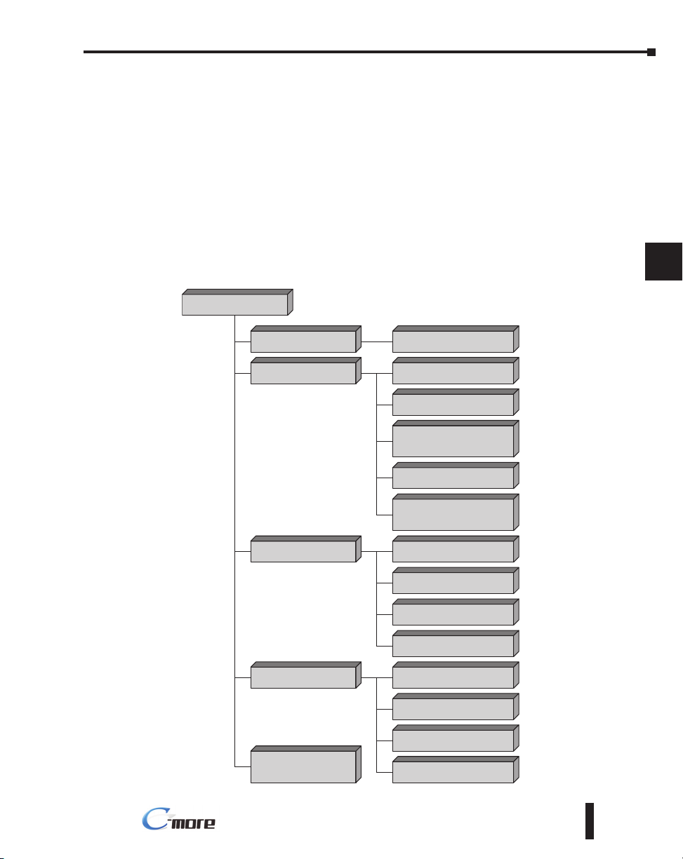
4.) System Setup Screens organized as shown in the following flowchart:
Chapter 5: System Setup Screens
1
1
2
2
3
3
4
4
5
5
Main Menu
[pg. 5-14]
Information
[pg. 5-15 to 5-18]
Setting
[pg. 5-19]
Test Menu
[pg. 5-25]
Memory
[pg. 5-35]
Touch Screen Calibration
(press upper left corner)
[pg. 5-14]
General/Memory/Ports/Error
[pg. 5-15 to 5-18]
Adjust Clock
[pg. 5-20]
Adjust Display
[pg. 5-21]
Adjust Touch Panel
(Touch Screen Calibration)
[pg. 5-22]
Beeper
[pg. 5-23]
IP Address Setting
(press upper left corner)
[pg. 5-24]
Test Touch Panel
[pg. 5-26]
Test Display
[pg. 5-27]
Test Communication Port
[pg. 5-28]
Test Beep/Sound
[pg. 5-33]
Backup
[pg. 5-37]
Restore
[pg. 5-44]
Clear Memory
[pg. 5-50]
Reset to Factory Default
[pg. 5-55]
6
6
7
7
8
8
9
9
10
10
11
11
12
12
13
13
14
14
A
A
B
B
C
c
D
D
EA-USER-M Hardware User Manual, 3rd Ed, Rev A, 06/20
5-3
Page 4
Chapter 5: System Setup Screens
®
Accessing the System Setup Screens (no project loaded)
1
1
2
2
3
3
4
4
5
5
6
6
7
7
8
8
9
9
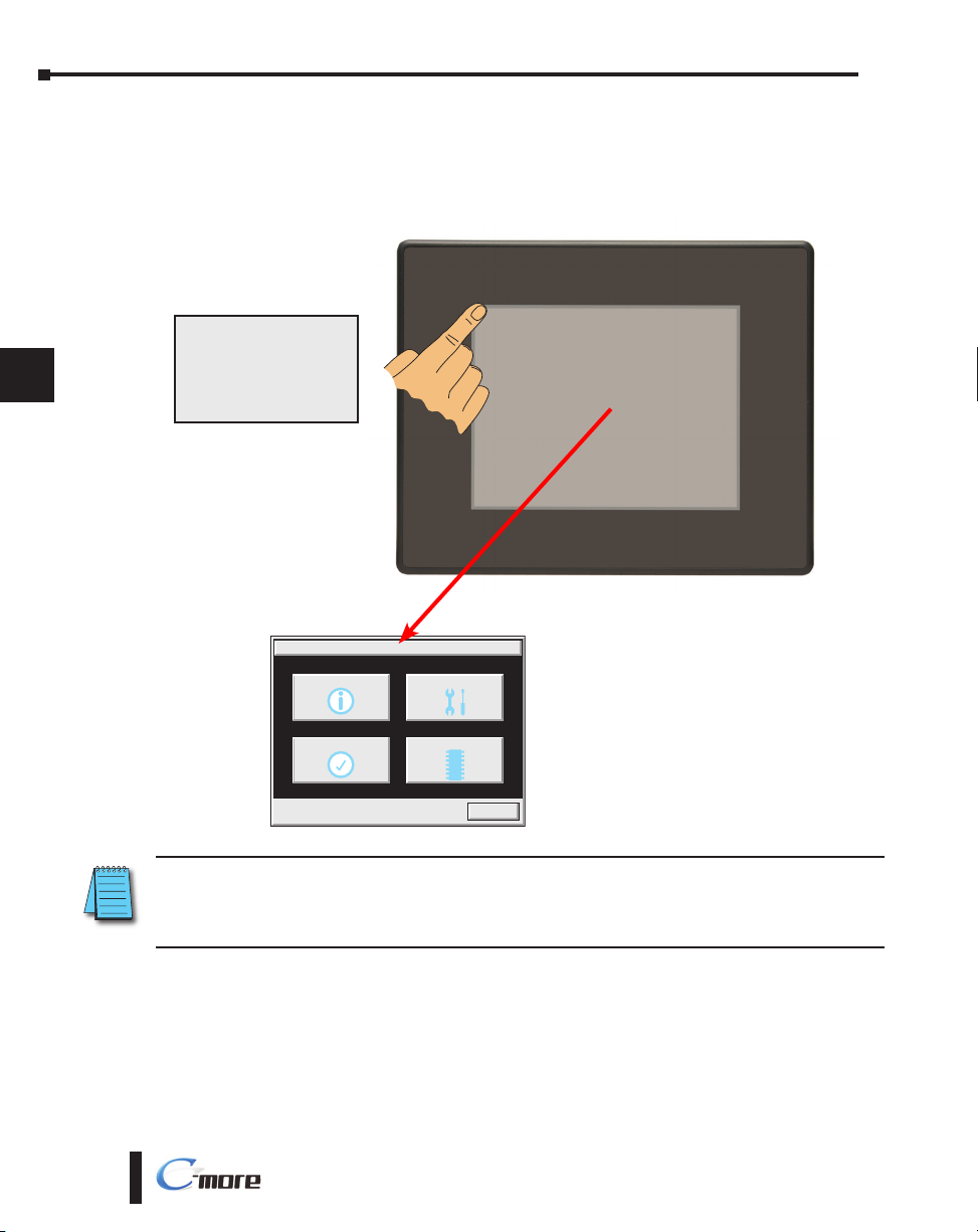
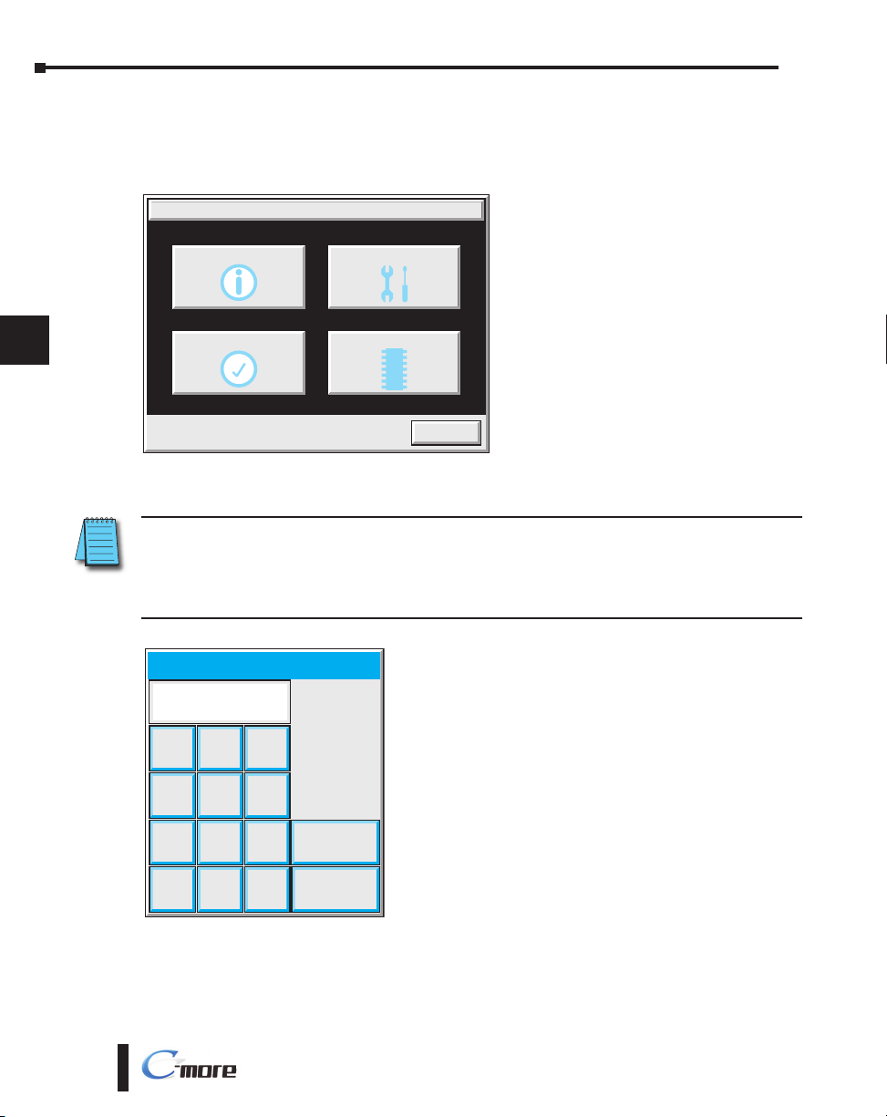
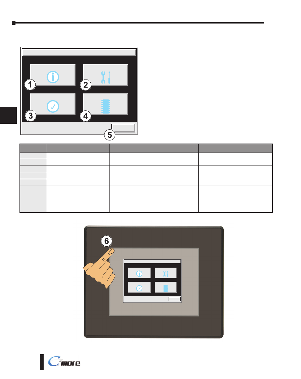
To access the Main Menu of the touch panel System Setup Screens prior to downloading a
project, press the extreme upper left corner of the panel display area for 3 seconds as shown
below. The Main Menu will then be displayed as shown below.
Press in the extreme upper
left corner for 3 seconds to
bring up the System Setup
Screens’ Main Menu.
10
10
11
11
12
12
13
13
14
14
A
A
B
B
C
c
D
D
5-4
MAIN MENU
Information Setting
Test Menu Memory
Exit
NOTE: The ability to directly activate the Main Menu of the System Setup Screens by pressing the upper left
corner of the touch panel for 3 seconds will only occur when there is no project loaded into the memory of the
panel. Refer to the next section on accessing the System Setup Screens with a project loaded for procedure
details and recommendations.
EA-USER-M Hardware User Manual, 3rd Ed, Rev A, 06/20
Page 5
Chapter 5: System Setup Screens
®
Accessing the System Setup Screens (with project loaded)
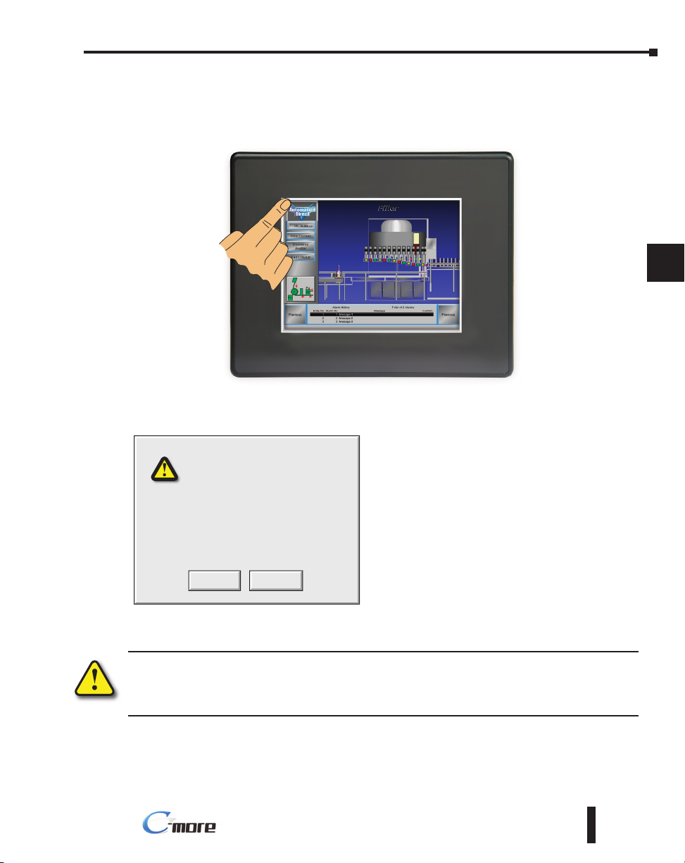
To access the Main Menu of the touch panel System Setup Screens with a project loaded into
memory, press the upper left corner of the panel display area for 3 seconds as shown below.
The following WARNING dialog box will appear on the the touch screen.
Dialog Box Actions:
• Pressing OK will display the system setup screen.
See the WARNING below!
System Screen Called
Activating System Screen will stop the
Panel Run Mode.
Do you want to continue?
CancelOK
• Pressing Cancel will take you back to the project
screen.
• Communications with the PLC is active while the
Warning is displayed.
• The dialog box will close if no action is taken for
60 seconds.
• The dialog box will not display if the touch panel
does not have a project loaded.
• The dialog box will not display if the System
Screen password is enabled.
1
1
2
2
3
3
4
4
5
5
6
6
7
7
8
8
9
9
10
10
11
11
12
12
13
13
14
14
A
5-5
A
B
B
C
c
D
D
Warning: Pressing OK at this point will STOP the PLC driver and therefore all communications between
the touch panel and PLC will cease. It is strongly recommended that the password system tag
“SYS SYSTEMSCREENPW” be enabled to add a safeguard step in accessing the system setup screens.
See the next section for a quick overview for setting the System Tags in the Event Manager Database.
EA-USER-M Hardware User Manual, 3rd Ed, Rev A, 06/20
Page 6
Chapter 5: System Setup Screens
®
System Setup Screens (no password enabled)
If no password is enabled for the system setup screens, then pressing the OK button in the
1
1
2
2
3
3
4
4
Warning dialog box will bring up the Main Menu as shown below. You can then proceed to
the other system setup screens.
Information Setting
MAIN MENU
5
5
6
6
7
7
8
8
9
9
10
10
11
11
12
12
13
13
14
14
A
A
Test Menu Memory
Exit
System Setup Screens (password enabled)
NOTE: If the password system tag SYS SYSTEMSCREENPW is enabled, procedure described on the next
page, then the Enter Security Code keypad shown below will be displayed. Entering the correct password
code will then bring up the Main Menu system setup screen. If the wrong password code is entered, the
keypad clear from its display the value entered and will stay present until the correct value is entered or the
Cancel key is pressed.
Enter Security Code
987
654
Enter
321
B
B
C
c
D
D
5-6
Cancel
CL0–
EA-USER-M Hardware User Manual, 3rd Ed, Rev A, 06/20
Page 7
Chapter 5: System Setup Screens
®
System Setup Screens – Enable Password in Software
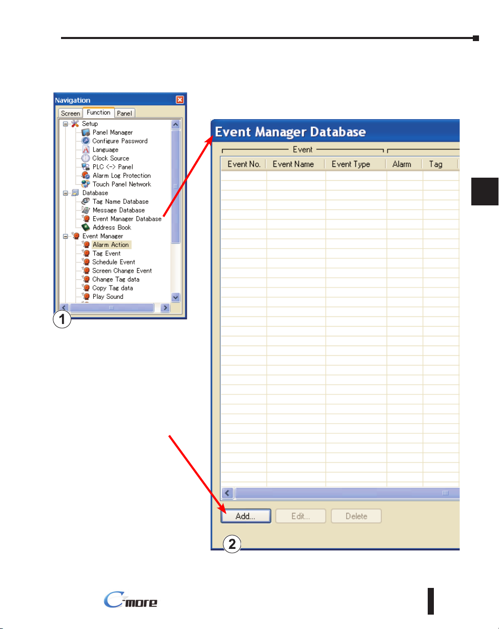
Under the C-more Programming Software’s Navigation window, select the Function tab, then
select the Event Manager’s Database function to display the Event
Manager Database shown below:
1
1
2
2
3
3
4
4
5
5
6
6
7
7
8
8
9
9
10
10
11
11
Click on the Add button
to add an event to the
database that will be used
to enable the System
Screen Password.
EA-USER-M Hardware User Manual, 3rd Ed, Rev A, 06/20
5-7
12
12
13
13
14
14
A
A
B
B
C
c
D
D
Page 8
Chapter 5: System Setup Screens
®
System Setup Screens – Enable Password (cont’d)
1
1
2
2
3
3
4
4
5
5
6
6
7
7
8
8
9
9
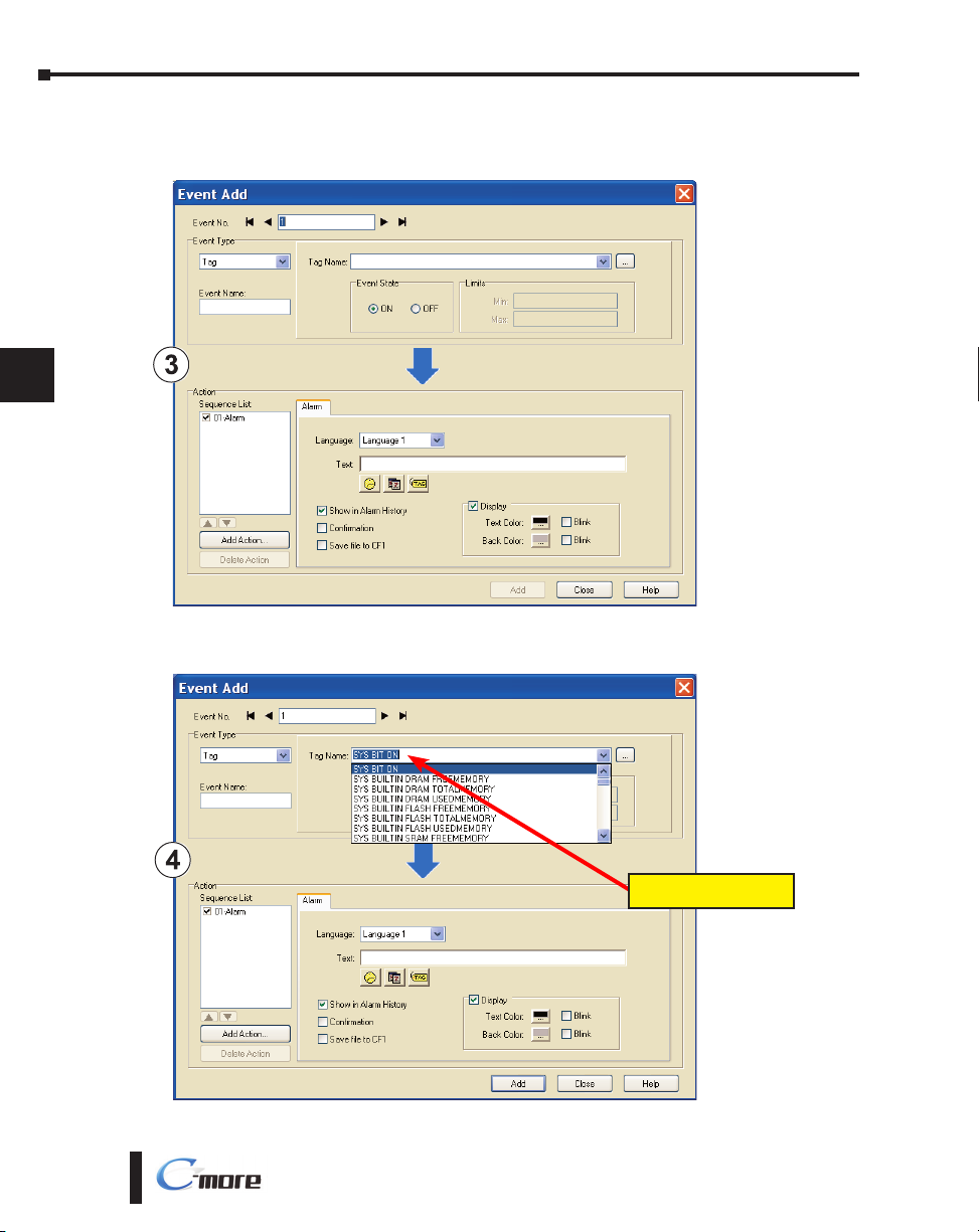
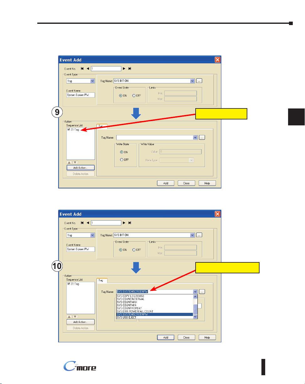
The Event Add dialog box will be displayed as shown next:
10
10
11
11
12
12
13
13
14
14
A
A
B
B
C
c
D
D
5-8
Click on the Tag Name: pull down menu and select the internal System Bit On
(SYS BIT ON) tag as shown. This will force the tag event type to be continuously active.
Tag Name: SYS BIT ON
EA-USER-M Hardware User Manual, 3rd Ed, Rev A, 06/20
Page 9
Chapter 5: System Setup Screens
®
System Setup Screens – Enable Password (cont’d)
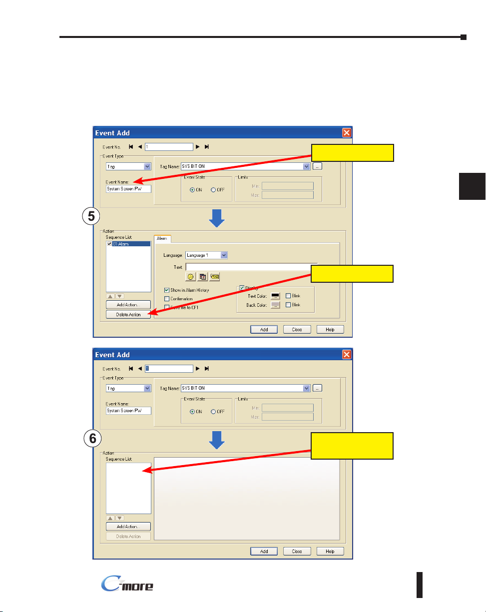
Use the Event Name: text box to document the event as “System Screen PW” for record
keeping This is optional.
In the Action box, click once on the displayed 01-Alarm under the Sequence List: so that
01-Alarm is highlighted. Then click the Delete Action button to remove the 01-Alarm.
Event Name:
Delete Action
1
1
2
2
3
3
4
4
5
5
6
6
7
7
8
8
9
9
10
10
11
11
12
12
13
13
14
5-9
14
A
A
B
B
C
c
D
D
The Sequence List will
now be cleared out.
EA-USER-M Hardware User Manual, 3rd Ed, Rev A, 06/20
Page 10

Chapter 5: System Setup Screens
®
System Setup Screens – Enable Password (cont’d)
1
1
2
2
3
3
4
4
5
5
6
6
In the Action box, click on the Add Action... button. This will bring up the Add Action dialog
box as shown below:
7
7
8
8
9
9
10
10
11
11
12
12
13
13
14
14
A
A
B
B
C
c
Add Action
Click on the Command: pull down list in the Add Command box, select Tag from the list,
then click OK.
Tag
D
D
5-10
EA-USER-M Hardware User Manual, 3rd Ed, Rev A, 06/20
Page 11
Chapter 5: System Setup Screens
®
System Setup Screens – Enable Password (cont’d)
A 01-Tag action item will then be added to the Sequence List.
1
1
2
2
3
3
4
4
01-Tag
Click on the Tag Name: pull down list down arrow in the Action box’s Tag tab, select SYS
SYSTEMSCREENPW from the list, and click OK.
SYS SYSTEMSCREENPW
5
5
6
6
7
7
8
8
9
9
10
10
11
11
12
12
13
13
14
14
A
A
B
B
C
c
D
D
EA-USER-M Hardware User Manual, 3rd Ed, Rev A, 06/20
5-11
Page 12
Chapter 5: System Setup Screens
®
System Setup Screens – Enable Password (cont’d)
1
1
2
2
3
3
4
4
5
5
6
6
7
7
8
8
9
9
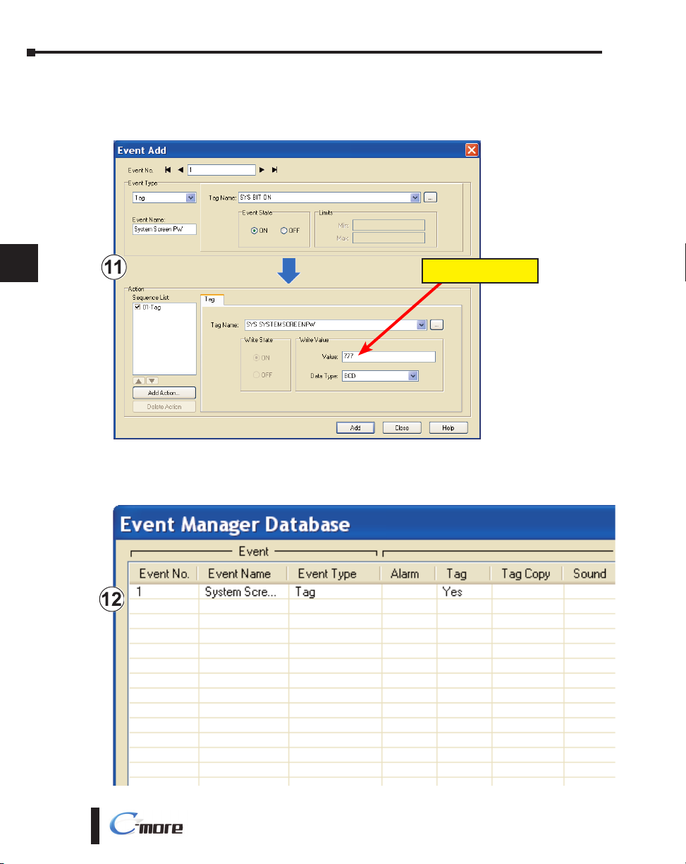
Enter a numeric value into the Value: box, such as “777”. This value becomes the Password
code to access the System Setup Screen’s Main Menu.
Password Value – 777
10
10
11
11
12
12
13
13
14
14
A
A
B
B
C
c
D
D
5-12
Click the Add button in the Event Add dialog box and then the Close button to return to the
Event Manager Database. You now will see that the first event in the database is for the System
Screen Password and it is enabled.
EA-USER-M Hardware User Manual, 3rd Ed, Rev A, 06/20
Page 13
®
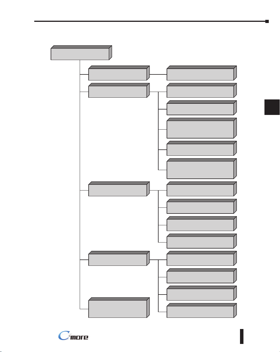
System Setup Screens Flowchart
Main Menu
[pg. 5-14]
Information
[pg. 5-15 to 5-18]
Chapter 5: System Setup Screens
General/Memory/Ports/Error
[pg. 5-15 to 5-18]
1
1
2
2
3
3
Setting
[pg. 5-19]
Test Menu
[pg. 5-25]
Memory
[pg. 5-35]
Adjust Clock
[pg. 5-20]
Adjust Display
[pg. 5-21]
Adjust Touch Panel
(Touch Screen Calibration)
[pg. 5-22]
Beeper
[pg. 5-23]
IP Address Setting
(press upper left corner)
[pg. 5-24]
Test Touch Panel
[pg. 5-26]
Test Display
[pg. 5-27]
Test Communication Port
[pg. 5-28]
Test Beep/Sound
[pg. 5-33]
Backup
[pg. 5-37]
Restore
[pg. 5-44]
4
4
5
5
6
6
7
7
8
8
9
9
10
10
11
11
12
12
13
13
14
14
A
A
B
B
Clear Memory
[pg. 5-50]
Touch Screen Calibration
(press upper left corner)
[pg. 5-14]
EA-USER-M Hardware User Manual, 3rd Ed, Rev A, 06/20
Reset to Factory Default
[pg. 5-55]
5-13
C
c
D
D
Page 14
Chapter 5: System Setup Screens
®
Main Menu
1
1
2
2
3
3
Information Setting
MAIN MENU
The Main Menu system setup screen is the top layer in
the menu structure.
The menu is displayed at full screen on the 6 inch
touch panel models. It is displayed in the center on the
8, 10, 12, or 15 inch models.
4
4
5
5
6
6
7
7
8
8
9
9
10
10
11
11
12
12
13
13
14
14
Test Menu Memory
Exit
Item No. Function Description Comment
1 Information
2 Setting
3 Test Menu
4 Memory
5 Exit
6 Touch Screen Calibration
Press to go to the Information Menu.
Press to go to the Setting Menu.
Press to go to the Test Menu.
Press to go to the Memory Menu.
Press to return to the user screen.
While the Main Menu system setup screen
is being displayed, the extreme upper left
corner of the touch panel can be pressed
for 3 seconds to access the Touch Screen
Calibration display.
MAIN MENU
Information Setting
This feature is only used if the touch
panel data becomes corrupted and
touching the Main Menu buttons
does not work. It allows a shortcut
to the touch panel calibration screen.
A
A
B
B
C
c
D
D
5-14
Test Menu Memory
Exit
EA-USER-M Hardware User Manual, 3rd Ed, Rev A, 06/20
Page 15
Chapter 5: System Setup Screens
®
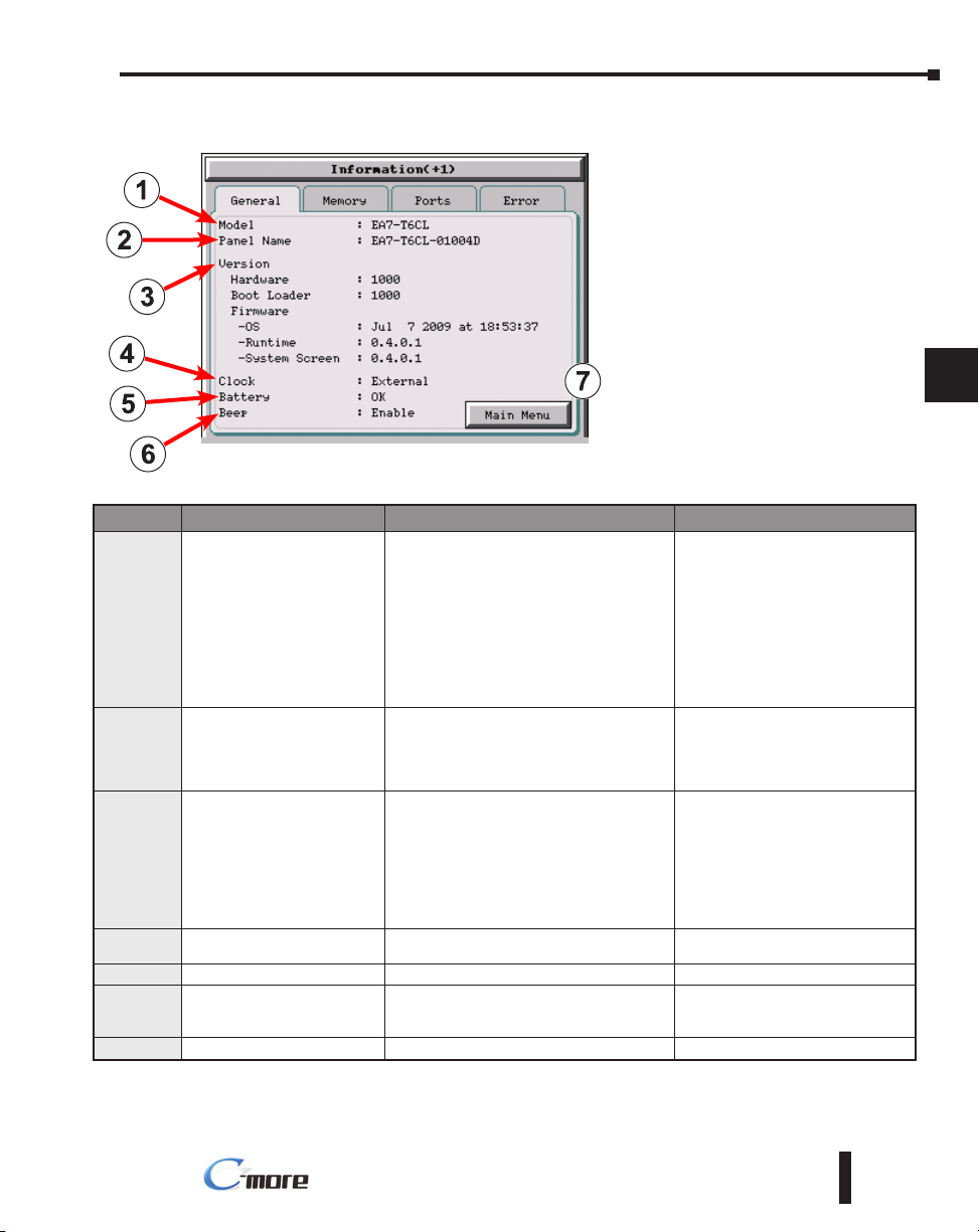
Information Menu – General tab
The General tab under the Information
menu provides detailed information
of the C-more Touch Panels model,
Panel Default Name based on Model
type and MAC address, hardware, boot
loader and firmware versions, etc.
Item No. Function Description Comments
EA7-S6M-R,
EA7-T6CL-R,
EA7-S6C-R,
EA7-S6M,
EA7-T6CL,
1 Model
2 Panel Default Name
3 Version
4 Clock
5 Battery
6 Beep
7 Main Menu
EA7-S6C,
EA7-T6C
EA7-T8C,
EA7-T10C,
EA7-T12C,
EA7-T15C
[Model Name]-01XXXX
“01 XXXX” is the lower 3 bytes of the
Mac Address
MAX: 15 characters (15 bytes)
1.)Hardware: XXXX
2.)Boot loader: XXXX
3.) Firmware
a) OS:Timestamp of NK.BIN file
b) Runtime: X.X.X.X (Version of
Runtime.EXE file)
c) System Screen: X.X.X.X (Version of
Panel.exe file)
Internal/External clock selection.
Battery status, either OK or Battery Low.
Enable/Disable the internal beeper.
Press to return to the Main Menu screen. Main Menu shown on page 5-14.
e.g.
EA7-S6M-01004D
This is the default name.
The name can be changed in the
C-more Programming Software.
Files reside in the C-more touch
panel’s memory.
Configured in the C-more
Programming Software.
Configurable in the Setting Menu –
Beeper shown on page 5-23 or in
the C-more Programming Software.
1
1
2
2
3
3
4
4
5
5
6
6
7
7
8
8
9
9
10
10
11
11
12
12
13
13
14
14
A
A
B
B
C
c
D
D
EA-USER-M Hardware User Manual, 3rd Ed, Rev A, 06/20
5-15
Page 16
Chapter 5: System Setup Screens
®
10 MB*
Project Memory
22 MB
Reserved
(Operating System,
Firmnware, etc.)
C-more
Internal
Memory
(Built-in)
189 KB
Log Buffer
(11 KB per Object)
33 KB
Alarm Log/
Count Buffer
32 KB
Retentive Tag Data
2 KB
SRAM Index
Project and user data reside
in SDRAM while the panel is
powered.
This data is backed-up internally
(32 MB Internal Flash memory not shown), and loaded/copied
into SDRAM on power up.
External Memory devices can
also be used for back-up of
C-more projects.
*Note: 12” and 15” units have:
■
64 MB SDRAM
■ 64 MB Internal Flash Back-up
■ 40 MB of Available Project
Memory
Alarm, Message, and PLC Log
Data is buffered in SRAM
pending transfer to an External
Memory device:
■ When the buffer nears full
■ Periodically, every 5 minutes
■ When one of the internal ‘eject’
tags is activated via an Object
or Event
Use additional memory for:
■ Project Transfers
■ Project Back-up/Restore
■ Alarm Logging
■ Message Logging
■ Screen Captures
■ PLC Data Logging
■ Additional Font Storage
USB Flash Drive
(USB Port Built-in)
CompactFlash Card
(Slot #1 Built-in)
CompactFlash Card
(Slot #2 Optional)
32 MB*
SDRAM
Memory
256 KB
SRAM
Memory
(Battery
Backed)
C-more
A
dditional
Memory
(Optional)
Any
capacity
available
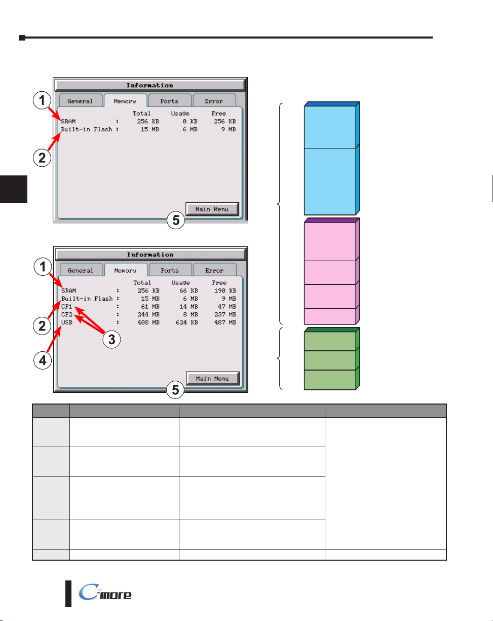
C-more Memory Organization
Information Menu – Memory tab
1
1
2
2
3
3
4
4
5
5
6
6
7
7
8
8
9
9
10
10
11
11
12
12
13
13
14
14
A
A
B
B
C
c
D
D
Item No. Function Description Comment
5-16
SRAM
1
System Memory
Built-in Flash
2
Memory
Expansion Memory
1.) CF1:
3
2.) CF2:
(only visible when present)
Expansion Memory
4
3.) USB:
(only visible when present)
5 Main Menu
EA-USER-M Hardware User Manual, 3rd Ed, Rev A, 06/20
1.) Total:
2.) Usage:
3.) Free:
1.) Total:
2.) Usage:
3.) Free:
1.) Total:
2.) Usage:
3.) Free:
Note: N/A - not available on base featured
models (–R)
1.) Total:
2.) Usage:
3.) Free:
Press to return to the Main Menu screen.
Size of unit displayed:
1.) KB
2.) KB or MB
3.) MB or GB
When size is 1 to 999 bytes.
It will be shown as 1KB.
Page 17
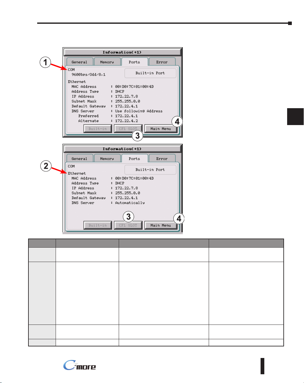
®
Information Menu – Ports tab
Chapter 5: System Setup Screens
1
1
2
2
3
3
4
4
5
5
6
6
7
7
8
8
9
9
Item No. Function Description Comment
COM
1
(Built-in Ports)
Ethernet
2
(Built-in Ports)
Ethernet
3
(CF1 Slot)
4 Main Menu
EA-USER-M Hardware User Manual, 3rd Ed, Rev A, 06/20
PLC Serial Communications Port Settings:
baud rate/party/data bit, stop bit
Ethernet Settings:
MAC Address: 00 D0 7C 01 XX XX
Address Type: DHCP/Static
IP Address:
Subnet Mask:
Default Gateway:
DNS: 1.) Automatically
2.) Use Designated Address
Note: N/A - not available on base featured
models (–R)
Future Future
Press to return to the Main Menu screen.
Configured in the C-more
Programming Software.
Configurable in the Setting Menu –
IP Address Setting shown on page
5-24 or in the C-more Programming
Software.
10
10
11
11
12
12
13
13
14
14
5-17
A
A
B
B
C
c
D
D
Page 18

Chapter 5: System Setup Screens
®
Information Menu – Error tab
1
1
2
2
3
3
Error message format
4
4
5
5
6
6
7
7
8
8
9
9
10
10
11
11
12
12
13
13
14
14
A
A
B
B
C
c
D
D
Error message format:
Item No. Function Description Comment
Order of error message functions:
Error Number, Date, Time, Error Port, Device Name, Error Type, PLC Device, Access Bytes, Error Message
1 Date
2 Time
3 Error Port
4 Device Name
5 Error Type
6 PLC Address
7 Access Bytes
8 Error Message
Error message navigation buttons:
Item No. Function Description Comment
1 Clear
2 Page Down
3 Page Up
4 Main Menu
Format: MM/DD/YY Date error occurred.
Format: HH/MM/SS Time error occurred.
PLC Serial Communications Port:
Ethernet:
The assigned device name in the
programming software.
RD: Read
WT: Write
The assigned address of the PLC that caused
the error.
The number of access bytes.
The error message is the same as the
message displayed in the upper left of the
C-more touch panel’s display.
Press to clear all error messages. This
button is grayed out when there are no error
messages to display.
Press to go to to the next page. This button is
grayed out when there is no error messages
on the next page.
Press to go to the previous page. This button
is grayed out when there is no error messages
on the previous page.
Press to return to the Main Menu screen.
Navigation buttons
Configurable in the C-more
Programming Software Panel
Manager
A list of Error Massages is shown in
Appendix A
5-18
EA-USER-M Hardware User Manual, 3rd Ed, Rev A, 06/20
Page 19

®
Setting Menu
Chapter 5: System Setup Screens
The Setting Menu is used to adjust the time &
date, adjust the contrast or brightness of the display
depending on which model is being used, adjust
(calibrate) the touch screen, and enable or disable the
internal beeper.
1
1
2
2
3
3
4
4
5
5
6
6
Item No. Function Description Comments
1 Adjust Clock
2 Adjust Display
3 Adjust Touch Panel
4 Beeper
5 Main Menu
6 IP Address setting
Press to go to the Adjust Clock screen.
Press to go to the Adjust Display screen.
Press to go to the Adjust Touch Panel screen.
Press to go to the Adjust Beeper screen.
Press to return to the Main Menu screen.
While the Setting Menu system setup screen is
being displayed, the extreme upper left corner of
the touch panel can be pressed for 3 seconds to
access the IP Address setting screen.
The IP Address setting screen is only
accessible form the Setting Menu
screen as described. There is no
direct button to call it from any of
the setup screens. The IP Address
can also be assigned in the C-more
Programming Software.
7
7
8
8
9
9
10
10
11
11
12
12
13
13
14
14
A
A
B
B
C
c
D
D
EA-USER-M Hardware User Manual, 3rd Ed, Rev A, 06/20
5-19
Page 20

Chapter 5: System Setup Screens
®
Setting – Adjust Clock
1
1
2
2
3
3
4
4
5
5
6
6
7
7
8
8
9
9
10
10
11
11
12
12
13
13
14
14
A
A
B
B
C
c
D
D
Color Touch Panel
Item No. Function Description Comments
Time: Each press of the Select button will
cycle thru the following settings.
1.) No Selection to Hours
2.) Hours to Minutes
3.) Minutes to Seconds
1 Select
2 Up
3 Down
4 OK
5 Cancel
NOTE: The function buttons used to adjust the clock settings on the panel’s setup screen are disabled if an
External clock source is selected in the C-more programming software. The choice of an internal or external
clock source is available by selecting Clock Source in the C-more programming software under the Main
Menu drop down function Setup.
NOTE: The panel’s clock can also be adjusted from the C-more programming software. The Adjust Clock
function can be accessed in the software by selecting Adjust Clock under the Main Menu drop down function
Panel or selecting Adjust Clock under the Panel tab in the software’s Navigation window.
4.) Seconds back to Hours
Date: Each press of the Select button will
cycle thru the following settings.
1.) Month to Day
2.) Day to Year
3.) Year back to Month
Press to increment the value by “1” with
each press.
Press to decrement the value by “1” with
each press.
Press to accept the changes.
Press to return to the Setting Menu screen
without accepting the changes.
Grayscale Touch Panel
5-20
EA-USER-M Hardware User Manual, 3rd Ed, Rev A, 06/20
Page 21

Chapter 5: System Setup Screens
®
Setting – Adjust Display
Color Touch Panel
Item No. Function Description Comments
The STN type display models can have the contrast adjusted. The TFT type display models can have the brightness
adjusted. See the table below.
1 Up
Press to increment the value by “1” with
each press.
Grayscale Touch Panel
1
1
2
2
3
3
4
4
5
5
6
6
7
7
8
8
9
9
10
10
2 Down
3 OK
4 Cancel
Model
TFT Models:
EA7-T6CL-R, EA7-T6CL, EA7-T6C
EA7-T8C, EA7-T10C,
EA7-T12C & EA7-T15C
STN Grayscale:
EA7-S6M-R &
EA7-S6M
STN Color:
EA7-S6C-R
EA7-S6C
Press to decrement the value by “1” with
each press.
Press to accept the changes.
Press to return to the Setting Menu screen
without accepting the changes.
Selection Range Default
Brightness Contrast Brightness Contrast
1 to 7 N/A 7 N/A
N/A 1 to 7 N/A 6
EA-USER-M Hardware User Manual, 3rd Ed, Rev A, 06/20
11
11
12
12
13
13
14
14
5-21
A
A
B
B
C
c
D
D
Page 22

Chapter 5: System Setup Screens
®
Setting – Touch Screen Calibration
1
1
2
2
3
3
4
4
5
5
6
6
7
7
8
8
9
9
10
10
Item No. Function Description Comment
This procedure is used to calibrate the touch screen to ensure accuracy of the touch areas. There
are five points on the touch screen that the calibration is based around. The adjustment relies
on very narrow areas for the calibration points.
NOTE: The panel will display the Touch Screen Calibration window on power up until the calibration
procedure is completed and saved.
The touch screen calibration crosshairs will
1 Points 1a thru 1e
2 Cancel
3 Press here to save & quit.
4 Press here to retry.
Touch Screen Calibration
Calibrate the Touch Screen by
touching the center of the crosshairs
+ with your finger or a stylus.
appear individually in the order of point 1a
thru 1e respectively as each proceeding
crosshair is pressed.
Press to return to the Setting Menu screen
without accepting the changes.
Press to accept the changes and return to the
Setting Menu screen.
The current adjustment data is canceled and
the procedure is returned to point 1a.
If the touched co-ordinate point is
too far off from normal, then the
procedure will return to Point 1a.
If you do not save, you will have to
calibrate the panel again after the
next power cycle.
Press here to save and quit.
11
11
12
12
13
13
14
14
A
A
B
B
C
c
D
D
5-22
Cancel
Press here to retry.
Points 1a thru 1e
EA-USER-M Hardware User Manual, 3rd Ed, Rev A, 06/20
Final
Page 23

®
Setting – Beeper
Chapter 5: System Setup Screens
This system setup screen function is used
to enable or disable the touch panel’s
internal beeper.
1
1
2
2
3
3
4
4
5
5
6
6
Item No. Function Description Comments
1 Yes
2 No
3 OK
4 Cancel
NOTE: The project settings in the C-more programming software Panel Manager will override the touch
panel’s internal setting upon initial download.
Change Enable to Beeper.
Change Disable to Beeper.
Press to accept the changes and return to the
Setting Menu screen.
Press to return to the Setting Menu screen
without accepting the changes.
7
7
8
8
9
9
10
10
11
11
12
12
13
13
14
14
A
A
B
B
C
c
D
D
EA-USER-M Hardware User Manual, 3rd Ed, Rev A, 06/20
5-23
Page 24

Chapter 5: System Setup Screens
®
Setting – IP Address Setting
1
1
2
2
3
3
4
4
5
5
6
6
Item No. Function Description Comment
7
7
8
8
9
9
10
10
11
11
12
12
13
13
14
14
A
A
B
B
C
c
1 DHCP
2 IP Address
IP Address
3
Subnet Mask
Default Gateway
4 Keypad
5 OK
6 Cancel
“DHCP” is enabled as the default when this
system setup screen is first selected.
All of the other selections on this screen are
dimmed when “DHCP” is selected and are
not available.
The “Use the following IP Address” setting is
selected when its radio button is pressed.
An IP Address can be assigned as follows:
1.) Select the address type:
a.) IP Address
b.) Subnet Mask
c.) Default Gateway
2.) Use the numerical keypad to input the
address. Use the decimal key to enter the
dot separator.
3.) Press the “ENT” key when finished with
each field.
Select the field that needs to be assigned by
touching the entry value and use the keypad
to enter the desired address.
The keypad is used to enter the Address:
Use the numeric keys and the “dot” key to
enter the address, e.g: 192.168.10.1
“ENT” = Enter key sets value
“CL” = Clear value entered
“DEL” = Delete 1 character with each press
Press to accept the changes and return to the
Setting Menu screen.
Press to return to the Setting Menu screen
without accepting the changes.
Note: If an Ethernet cable is not
connected to the touch panel from
an active Ethernet device, then the IP
Address will show as 0.0.0.0.
Each field can be independently
assigned.
The “ENT” key must be pressed to
accept the entry. If the “ENT” key
is not pressed, then the previous
value will remain when another area
is selected or the “Cancel” key is
pressed.
D
D
5-24
EA-USER-M Hardware User Manual, 3rd Ed, Rev A, 06/20
Page 25

Chapter 5: System Setup Screens
®
Test Menu
The Test Menu gives the user the ability to test the
operation of the touch screen, test the LCD display,
test the various communication ports, and also test
the internal beeper and the audio line out through an
user supplied amplified (stereo) speaker(s).
Item No. Function Description Comments
1 Test Touch Panel
2 Test Display
3 Test Communication Port
4 Test Beep/Sound
Press to go to the Test Touch Panel screen.
Press to go to the Test Display screen.
Press to go to the Test Communication Port
screen.
Press to go to the Test Beep/Sound screen.
1
1
2
2
3
3
4
4
5
5
6
6
7
7
8
8
9
9
10
10
5 Main Menu
Press to return to the Main Menu screen.
EA-USER-M Hardware User Manual, 3rd Ed, Rev A, 06/20
11
11
12
12
13
13
14
14
5-25
A
A
B
B
C
c
D
D
Page 26

Chapter 5: System Setup Screens
®
Test Menu – Test Touch Panel
1
1
2
2
3
3
4
4
5
5
6
6
7
7
Item No. Function Description Comments
8
8
9
9
1 Touch area
Display Size Touch Area
6 Inch 320 X 240
8/10 Inch 640 X 480
12 Inch 800 X 600
15 Inch 1024 X 768
Using this test, normal or unusual operation of the
analog touch panel can be determined.
Testing:
If an area of the touch screen is suspected to be
inoperable, touch that area of the screen while in
the Test Touch Panel screen mode. The screen
pixels should turn black in that area. If the screen
pixels do not turn black when touched, then the
touch screen is defective or needs to be calibrated.
See Setting - Adjust Touch Screen on page 5-22.
Both the title bar (Test Touch Panel)
and Cancel button can be drawn
across to test the touch operation.
10
10
11
11
12
12
13
13
14
14
A
A
B
B
C
c
D
D
5-26
2 Cancel
Note: The Touchscreen is designed to respond to a single touch. If it is touched at multiple points at the
same time, an unexpected object may be activated.
EA-USER-M Hardware User Manual, 3rd Ed, Rev A, 06/20
Press to return to the Test Menu screen.
Page 27

®
Test Menu – Test Display
There are two different test patterns that may be run on the LCD display to allow the user to
check for display screen defects. If the screen is not touched within 3 seconds of Test Pattern
1 being displayed, then Test Pattern 2 will be displayed until the screen is touched, otherwise
Test Pattern 1 will remain until cancelled.
Test Pattern 1 displays a test pattern of 16 grayscale graduations and RGB colors.
Chapter 5: System Setup Screens
1
1
2
2
3
3
4
4
5
5
6
6
7
7
Test Pattern 2 will follow the pattern as shown in the following chart with the color wiping
across the screen in the direction indicated by the arrows, then repeats:
Color 1st Time 2nd Time 3rd Time 4th Time
RED
GREEN
BLUE
Item No. Function Description Comments
Touch the Test Display
1
screen.
2 Cancel (Test Pattern 1)
Touch Anywhere
3
(Test Pattern 2)
Test Results: If any pixels on the screen do not appear the same color as the surrounding pixels,
the LCD screen may be defective. A single pixel gone bad is relatively common. Surrounding
pixels going bad over time is another indication the LCD screen may be defective.
Press the screen anywhere except the Cancel
button and the shown Test Pattern 1 remains.
Press to return to the Test Menu screen.
Touch the sceen anywhere during Test
Pattern 2 and return to the Test Menu screen.
If the Test Display screen is not
touched, then in three seconds the
display will move to Test Pattern 2.
8
8
9
9
10
11
1
12
12
13
13
14
14
A
A
B
B
C
c
D
D
EA-USER-M Hardware User Manual, 3rd Ed, Rev A, 06/20
5-27
Page 28

Chapter 5: System Setup Screens
®
Test Menu – Test Communication Ports: Serial
1
1
2
2
3
3
4
4
5
5
6
6
7
7
Item No. Function Description Comments
8
8
1 Loop Back Test
This function checks the serial comm port for
proper operation with a loop back connector.
The following test can be used to check the operation
of the serial communication port, with the use of a
loop back connector and can also check the status
of the serial communications to any connected and
configured PLC.
Continued on the next two pages.
9
9
10
10
11
11
12
12
13
13
14
14
A
A
B
B
C
c
D
D
2 PLC Enquiry Test
3 Cancel
RS-232 Loop-back Connector
2
TXD
3
RXD
7
CTS
8
RTS
Wiring Diagram
This function allows the ability to select any
PLC that that may be connected to the touch
panel via a serial connection and checks
to see if the communications are working
correctly.
Press to return to the Test Menu screen.
15-pin D-sub
(male)
15
1
Note: The PLC serial communications
port settings must be configured in
the C-more programming software.
RS-422/485 Loop-back Connector
7
8
9
11
10
12
Wiring Diagram
CTS
RTS
RXD+
TXD+
RXD–
TXD–
15-pin D-sub
(male)
15
1
5-28
EA-USER-M Hardware User Manual, 3rd Ed, Rev A, 06/20
Page 29

®
Test Menu – Serial Port Test
PLC Serial Comm Port – Loop Back Test
Chapter 5: System Setup Screens
1
1
Item No. Function Description Comments
1.) When testing an RS-232C serial
connection, connect pin 2 to 3 and pin
7 to 8 on an appropriate D-SUB 15-pin
male connector and plug it into the serial
PLC comm port on the rear of the touch
Determine Loop Back
1
Connector
2 Start Test
3 Test Results
4 Cancel
panel.
2.) When testing an RS-422 or RS-485 serial
connection, connect pin 9 to 11, pin 10
to 12 and pin 7 to 8 on an appropriate
D-SUB 15-pin male connector and plug it
into the serial PLC comm port on the rear
of the touch panel.
Press the Loop Back Test button to start the
serial comm port test.
1.) Bytes Sent:
The number of bytes sent after a test is
started.
2.) Receive Counts:
The number of bytes which are received
after the test is started.
3.) Error Counts:
The number of bytes which have not been
received after the test is started.
4.) RTS/CTS Test: Pass/Fail
RTS is turned on and if CTS receives
the signal then the test shows “Pass”,
otherwise the test shows “Fail”.
Press to return to the Test Comm. Port
screen.
Note: The test will continue to run
until the Cancel button is pressed.
If there are any error counts, check
the loop back connector. If it is OK,
call Tech Support.
2
2
3
3
4
4
5
5
6
6
7
7
8
8
9
9
10
10
11
11
12
12
13
13
14
14
A
A
B
B
C
c
D
D
EA-USER-M Hardware User Manual, 3rd Ed, Rev A, 06/20
5-29
Page 30

Chapter 5: System Setup Screens
®
Test Menu – PLC Enquiry Test: Serial Connection
1
1
2
2
3
3
4
4
5
5
6
6
7
7
Item No. Function Description Comments
Select any PLC that is shown in the drop
8
8
1 Select PLC
down menu. The PLC selected will connect to
the touch panel at the time of a test.
This function allows the ability to select any PLC
that may be connected to the touch panel through
a serial comm. port connection and checks to see if
the communications are working correctly.
Note: The communications protocol for
the PLC being selected must be configured
the same as the C-more touch panel. The
touch panel’s PLC serial communications are
configured using the C-more Programming
Software’s Panel Manager.
Only PLC’s that have been configured
in the C-more Programming Software
will appear in the Select PLC: list.
9
9
10
10
11
11
12
12
13
13
14
14
A
A
B
B
C
c
D
D
2 PLC Enquiry Test
3 Cancel
Four test read packets are sent to the selected
PLC.
Test result will be either Pass or Fail.
Press to return to the Test Menu screen.
5-30
EA-USER-M Hardware User Manual, 3rd Ed, Rev A, 06/20
Page 31

Chapter 5: System Setup Screens
®
DL06 PLC
Test Menu – Test Communication Ports: Ethernet
Test Comm. Port
Serial
Link : Online
Address : Static
192.168.100.4
Item No. Function Description Comments
1 Ethernet Connected
2 PLC Enquiry Test
3 Cancel
Example of displayed message when the touch
panel’s Ethernet port is not connected.
Serial
Link : Offline
Address : Static
0.0.0.0
Ethernet
Test Comm. Port
Ethernet
Select PLC:
DL ECOM Module
192.168.100.3
PLC Enquiry Test
Select PLC:
PLC Enquiry Test
Cancel
This area displays information to whether
an Ethernet link has been established for
the touch panel’s Ethernet comm port or
not. Displays panel’s IP address and shows
whether it is static or assigned by a DHCP
server.
This function allows the ability to select
any PLC configured in the project that may
be connected to the touch panel via an
Ethernet connection and checks to see if the
communications are working correctly.
Press to return to the Test Menu screen.
The following test feature can be used to check
the operation of the Ethernet communication
port by indicating if an Ethernet link has been
established or not, and can also check the status of
the Ethernet communications to any connected
PLC.
Base featured models (-R) do not include
an Ethernet port, therefore this check is not
displayed.
Note: The communications protocol for the
PLC being selected must be configured the
same as the C-more touch panel. The touch
panel’s PLC serial communications are
configured using the C-more Programming
Software’s Panel Manager.
Typical Ethernet connection
with Ethernet switch.
Stride™
Ethernet Switch
10/100 Base-T
(such as SE-SW5U)
H0-ECOM/H0-ECOM100
Ethernet Module
1
C-more
Touch Panel
Ethernet
Port
1
1
2
2
3
3
4
4
5
5
6
6
7
7
8
8
9
9
10
10
11
11
12
12
13
13
14
14
A
A
B
B
(Bottom View)
Ethernet CAT5
Cancel
EA-USER-M Hardware User Manual, 3rd Ed, Rev A, 06/20
Cable - Straight-thru
5-31
C
c
D
D
Page 32

Chapter 5: System Setup Screens
®
Test Menu – PLC Enquiry Test: Ethernet Connection
1
1
2
2
3
3
4
4
5
5
6
6
7
7
Item No. Function Description Comments
8
8
Serial
Link : Online
Address : Static
192.168.100.4
1 Select PLC
Test Comm. Port
Ethernet
PLC Enquiry Test
Select PLC:
DEV001
DEV001
DEV008
DEV009
DEV010
DEV011
Cancel
Select any PLC that is shown in the drop
down menu.
This function allows the ability to select any
PLC configured in the project that may be
connected to the touch panel through an
Ethernet port connection and checks to see if the
communications are working correctly.
Note: The communications protocol for the
PLC being selected must be configured the
same as the C-more touch panel. The touch
panel’s PLC serial communications are
configured using the C-more Programming
Software’s Panel Manager.
9
9
10
10
11
11
12
12
13
13
14
14
A
A
B
B
C
c
D
D
2 PLC Enquiry Test
3 Cancel
The following are the steps that the Ethernet
PLC Enquiry Test performs:
1.) Ping the network 4 times for the PLC
selected.
2.) Four of the test read packets are sent to
the selected PLC.
Test result will be either Pass or Fail.
However, if the result of pinging the network
shows an error, the test is stopped.
Press to return to the Test Menu screen.
5-32
EA-USER-M Hardware User Manual, 3rd Ed, Rev A, 06/20
Page 33

Chapter 5: System Setup Screens
®
Test Menu – Test Beep/Sound
Item No. Function Description Comments
The internal Beeper can be tested from this
system setup screen whether the Beeper is
1 Beep Test
2 Cancel
enabled or disabled. After the Beep Test
button is pressed then released, the Beeper
will sound for 500 msec.
Press to return to the Test Menu screen.
1
1
2
2
3
3
4
4
5
5
6
6
7
7
8
8
9
9
10
10
11
11
12
12
13
13
14
14
A
A
B
B
C
c
D
D
EA-USER-M Hardware User Manual, 3rd Ed, Rev A, 06/20
5-33
Page 34

Chapter 5: System Setup Screens
®
Test Menu – Test Beep/Sound (cont’d)
1
1
2
2
3
3
4
4
5
5
6
6
7
7
Warning: Hearing damage may occur if the volume on the user supplied external amplified speaker is
8
8
9
9
10
10
11
11
12
12
Item No. Function Description Comments
set too high.
1 Speaker Test
2 Cancel
The Speaker Test function requires that a
speaker(s) with an amplifier (can be stereo)
be connected to the Audio Line Out stereo
jack on the rear of the touch panel.
After the Speaker Test button is pressed then
released, a system provided Test.WAV file will
play once.
Press to return to the Test Menu screen.
13
13
14
14
A
A
B
B
C
c
D
D
5-34
EA-USER-M Hardware User Manual, 3rd Ed, Rev A, 06/20
Page 35

Chapter 5: System Setup Screens
®
Memory Menu
The user’s project, system, log and recipes files can
be backed up and restored to either a CompactFlash
memory card (CF1 or CF2), or a USB memory device.
From this menu the user can also clear the project log
files. The user also has the ability to clear the memory
within the C-more touch panel.
Base featured models (-R) do not include CF1 or CF2.
Item No. Function Description Comments
Any USB 1.1 pen drive or
CompactFlash memory device
capacity available is supported.
The backup data files are created and
copied to a folder on the memory
device named “EA_Memory Copy.”
The project file is named
StartupStorage.eas
“Log” and “Recipe” folders with the
appropriate data files are also created
on the memory device.
A folder on the memory device
named “EA_Memory Copy” must
exist containing a file named
“StartupStorage.eas”. The project
data file is stored in this file, and if the
system data file was backed up, it also
will be stored in this file. Any backed
up log or recipe data files will be
located under the appropriate “Log”
or “Recipe” folders.
Can only clear project, log and recipe
data files of the Built-in FLASH
memory.
Can clear entire contents or individual
data files of external memory devices.
Clears all project memory.
1 Backup
2 Restore
3 Clear Memory
4 Reset to Factory Default
Backup project, system, log & recipe files to
the following memory devices:
USB port - Type A: USB pen drive
CF Slot #1 (standard port): CompactFlash
CF Slot #2 (optional port): CompactFlash
See page 5-37 for details.
Restore project, system, log & recipe files
to the internal memory from one of the
following memory devices:
USB port - Type A: USB pen drive
CF Slot #1 (standard port): CompactFlash
CF Slot #2 (optional port): CompactFlash
See page 5-44 for details.
Clear selected data files from the memory
of the following internal memory or external
memory devices:
Built-in FLASH Memory
USB port - Type A: USB pen drive
CF Slot #1 (standard port): CompactFlash
CF Slot #2 (optional port): CompactFlash
See page 5-50 for details.
The touch panel’s internal memory is set to
the original factory defaults.
1
1
2
2
3
3
4
4
5
5
6
6
7
7
8
8
9
9
10
10
11
11
12
12
13
13
14
14
A
A
B
B
C
c
5 Main Menu
Press to return to the Main Menu screen.
EA-USER-M Hardware User Manual, 3rd Ed, Rev A, 06/20
5-35
D
D
Page 36

Chapter 5: System Setup Screens
®
Project Executed from CompactFlash (CF Slot #1)
1
1
2
2
3
3
4
4
5
5
6
6
7
7
8
8
9
9
If a CompactFlash card is located in the CF1 slot at the time a project is transferred to the
panel, the project will be stored on the CompactFlash card, not in the internal Built-in FLASH
memory.
If CF1 slot contains a CompactFlash with a project and:
1.) The touch panel’s power is cycled, then
2.) The project file stored on the CompactFlash is loaded into the touch panel’s internal DRAM
memory and executed. Please note that the project stored in the panel’s internal FLASH memory is
NOT loaded into the internal DRAM memory when a CompactFlash memory card is present. Any
project in the internal FLASH memory is cleared.
Warning: During power up with a CompactFlash plugged into the CF1 Slot, please do not remove the
memory card from the slot. Damage to the CompactFlash and possibly the touch panel may result.
Warning: After a firmware update, the project files which are located in either the touch panel’s internal
FLASH memory or the CompactFlash plugged into CF1 Slot are cleared. The programming software
will need to be used to Transfer the project file back into the panel. If you wish to retain the project on
the CompactFlash, power down the panel and remove the CompactFlash before performing a firmware
upgrade.
10
10
11
11
12
12
13
13
14
14
A
A
B
B
C
c
D
D
5-36
Increasing Project Memory Size using a CompactFlash in CF1 Slot:
If a project is transferred to the panel with a CompactFlash card in CF1 Slot, the Font and
Recipe data files are not included in the 10MB (40MB for 12” and 15” models) project size.
Therefore using CF1 can allow a project to be loaded that is larger than 10MB if the excessive
size is caused by Fonts and/or Recipe Sheets.
EA-USER-M Hardware User Manual, 3rd Ed, Rev A, 06/20
Page 37

®
Memory – Backup
Backup
Step–1 : Select backup device
123
Total : N/A
Free : N/A
Step–1 : Select backup device
123
Total : N/A
Free : N/A
CF1
Backup
CF1
Total : 488 MB
Free : 488 MB
Total : N/A
Free : N/A
Total : 488 MB
Free : 488 MB
Total : N/A
Free : N/A
USB
USB
CF2
CF2
Chapter 5: System Setup Screens
The Memory - Backup selection allows you to
backup the panel’s Project, Log files, Recipe
files or even the System (firmware & OS) files to
either a CompactFlash (CF) or USB pen drive.
The available memory devices will be displayed
showing the total and free available memory for
that device. If the device is not available, it will be
grayed out. The Next button is grayed out until
a device is selected.
The Cancel button can be pressed at any time to
return to the Memory Menu screen.
CancelNext >>
This is an example of a USB memory device
selected to be used for backing up the panel’s
data file(s).
The selected device is highlighted. Pressing again
un-selects it.
When there are more than two available backup
devices, the one selected will be highlighted. If
there is only one available memory device, it still
needs to be highlighted in order to go to the next
step.
CancelNext >>
Press the Next button to continue to Step 2.
1
1
2
2
3
3
4
4
5
5
6
6
7
7
8
8
9
9
10
10
11
11
12
12
13
13
Note: If you have a memory device inserted into the proper port on the touch panel, but it doesn’t show up as
highlighted in Step 1 of the Backup setup screen, then try a different device to determine if the memory device
is defective or if there is a possible problem with the memory device connection. It may not be compatible
with the panel. This rarely happens with CF memory, but some USB pen drives are not USB 1.1 compatible
and will not work with C-more touch panels. Also, some USB pen drives may take several minutes before
they are recognized by the panel.
Please read the explanation for the availability of CF1 under different conditions as shown
on the next two pages.
EA-USER-M Hardware User Manual, 3rd Ed, Rev A, 06/20
14
14
5-37
A
A
B
B
C
c
D
D
Page 38

Chapter 5: System Setup Screens
®
Memory – Backup (cont’d)
1
1
2
2
3
3
4
4
CF1 Availability Explanation:
Backup
Step–1 : Select backup device
123
Total : N/A
Free : N/A
If there is no CompactFlash inserted into CF1
Slot, then the CF1 button’s Total and Free
memory will show as N/A and be grayed out.
USB
5
5
6
6
7
7
8
8
9
9
10
10
11
11
12
12
13
13
14
14
A
A
Total : N/A
Free : N/A
Step–1 : Select backup device
123
Total : 121 MB
Free : 99 MB
CF1
CF1
Backup
Total : N/A
Free : N/A
Total : N/A
Free : N/A
Total : N/A
Free : N/A
CF2
CancelNext >>
If the panel is powered up or rebooted with
a CompactFlash inserted into CF1 Slot, then
the CF1 button’s Total and Free memory will
be displayed.
USB
CF2
CancelNext >>
B
B
C
c
D
D
5-38
EA-USER-M Hardware User Manual, 3rd Ed, Rev A, 06/20
Page 39

®
Memory – Backup (cont’d)
CF1 Availability Explanation (cont’d):
Backup
Step–1 : Select backup device
123
Total : N/A
Free : N/A
Total : N/A
Free : N/A
Below is an example of the folder and file structure that is stored on the CompactFlash
in the CF1 Slot for a project that was directly transferred from the C-more Programming
Software’s Project Transfer function when viewed in Windows® Explorer on a PC.
Folders
TOSHIBA512M (F:)
Font
Log
Mmd
Prj
Recipe
USB
CF2
arial_1_30.ttf
TrueType font file
151 KB
DEV001.inf
Setup Information
2 KB
EARun.atr
ATR File
1 KB
EARun.net
NET File
1 KB
EARun.prj
PRJ File
1 KB
EARun.tag
TAG File
4 KB
INTERNAL.inf
Setup Information
2 KB
Scr1.scr
AutoCAD LT Script
1 KB
TransFile.ini
Configuration Settings
1 KB
Chapter 5: System Setup Screens
1
1
If a CompactFlash is inserted into CF1 Slot
2
and a project is transferred using the C-more
Programming Software’s Project Transfer
utility Panel > Transfer, then the CF1 will
not show up in the Memory - Backup Step
1 device choices. The CompactFlash will
have the runtime files stored on it that get
loaded into the touch panel’s internal DRAM
memory when powered up or rebooted.
CancelNext >>
X
Font Files used in
Project
Log files.
Project Files
Max: 10MB for 6” - 10”
40MB for 12” & 15”
Recipe Sheet files.
2
3
3
4
4
5
5
6
6
7
7
8
8
9
9
10
10
11
11
12
12
13
13
14
14
A
A
B
B
C
c
D
D
EA-USER-M Hardware User Manual, 3rd Ed, Rev A, 06/20
5-39
Page 40

Chapter 5: System Setup Screens
®
Memory – Backup (cont’d)
1
1
2
2
3
3
4
4
5
5
6
6
7
7
8
8
9
9
10
10
11
11
12
12
13
13
Note: The following definitions are for the various file types that can be backed up:
Project data – consists of the actual developed project data that is created in the C-more programming
software and includes all functionality, objects, screens, tag names, labels, comments, graphics, etc.
Included in backup file name StartupStorage.eas.
Recipe data – consists of all the data values and labels that have been created for the various recipe
sheets. Includes all recipe sheets loaded to the panel. Only recipe sheets used in the project are loaded to
the panel.
System data – consists of the operating system, firmware and run time files. Included in backup file name
StartupStorage.eas.
Log data – consists of the Alarm Log, Message Log and Trend Data Logging files.
Backup
Step–2 : Select Data Area to Backup
123
Project
Total : 172 KB
Log
Total : 268 KB
<< Prev.
Backup
Step–2 : Select Data Area to Backup
123
Project
Total : 172 KB
Recipe
Total : 1 KB
System
Total : 16 MB
CancelNext >>
Recipe
Total : 1 KB
Select the data file(s) to be backed up by
pressing the appropriate data file button.
The selection will be highlighted.
Pressing the highlighted data file button
again will turn it off.
The Next >> button will stay grayed out until
at least one data file is selected.
Any file type not available will be grayed
out.
This is an example of data files selected for
backing up.
The selected data files are highlighted.
14
14
A
A
B
B
C
c
D
D
5-40
Total : 268 KB
Log
<< Prev.
Note: In the case of the Project and System files, these can be Restored later to another panel.
In the case of the Recipe files, they can be edited externally from the panel and then Restored to the panel.
The Log files are for viewing purposes only.
See Page 5-44 for instructions on Restoring the Project, System and or Recipe files to a Panel.
EA-USER-M Hardware User Manual, 3rd Ed, Rev A, 06/20
System
Total : 16 MB
CancelNext >>
The Next >> button is now enabled.
Pressing Cancel will return to the previous
menu.
Press the Next button to continue.
Page 41

®
Memory – Backup (cont’d)
Backup Data Files Naming and Organization
The following graphic shows how the various data files are organized on the memory
device when doing a Backup and also the file naming convention that is used when
viewed in Windows® Explorer on a PC.
Chapter 5: System Setup Screens
1
1
2
2
3
3
Folders
Desktop
My Documents
My Computer
Local Disk (C:)
DVD/CD-RW Drive (D:)
Removable Disk (E:)
TOSHIBA512M (F:)
EA_MemoryCopy
StartupStorage.eas
EAS File
160 KB
Log
Alarm_080131.txt
Text Document
1 KB
Screen1.jpg
320 x 240
JPEG Image
Recipe
Steel.csv
Microsoft Office Excel Comma ...
1 KB
X
Backup memory device
Project & System
backup file.
Log backup files.
Recipe Sheet
backup files.
4
4
5
5
6
6
7
7
8
8
9
9
10
10
11
11
12
12
13
13
14
14
A
A
B
B
C
c
D
D
EA-USER-M Hardware User Manual, 3rd Ed, Rev A, 06/20
5-41
Page 42

Chapter 5: System Setup Screens
®
Memory – Backup (cont’d)
1
1
2
2
3
3
4
4
5
5
6
6
7
7
8
8
9
9
10
10
11
11
12
12
The next system setup screen allows the
verification of the data file selections. When
the OK button is pressed, the backup begins.
The user can return to the previous screen by
pressing the << Prev button.
This message is displayed during the Backup
copying process. Press the Cancel button to
abort the backup.
The following text is shown in the copying
progress message box:
Copy to USB Memory:
“Please do not Power Off or Remove USB”
Copy to CF1 or CF2:
“Please do not Power Off or Remove CF”
Warning: During the copying process, Do
not power off the touch panel or remove
the memory device.
13
13
14
14
A
A
B
B
C
c
D
D
5-42
This message is displayed to indicate the Backup
is complete. Press the OK button to return to the
previous menu selection.
EA-USER-M Hardware User Manual, 3rd Ed, Rev A, 06/20
Page 43

®
Memory – Backup (cont’d)
Chapter 5: System Setup Screens
Warning Messages
If the destination does not have enough
space to store the selected memory size, then
the message shown here will be displayed.
Press the OK button to clear the warning
message.
The warning message will read “Not enough
Memory Space in %Device%”.
%Device% will show either “CF1”, “CF2”, or
“USB”.
1
1
2
2
3
3
4
4
5
5
6
6
7
7
This warning message will be displayed if the
backup Memory device fails or is removed
during the backup. Press the OK button to
clear the warning message.
The warning message will read “Backup
Failed. “%Device% cannot be found”.
%Device% will show either “CF1”, “CF2”, or
“USB”.
Refer to Chapter 8: Troubleshooting for
additional help.
For any other reason the backup fails, then
this warning message will be displayed. Press
the OK button to clear the warning message.
The warning message will read “Backup
Failed”.
Refer to Chapter 8: Troubleshooting for
additional help.
8
8
9
9
10
10
11
11
12
12
13
13
14
14
A
A
B
B
C
c
D
D
EA-USER-M Hardware User Manual, 3rd Ed, Rev A, 06/20
5-43
Page 44

Chapter 5: System Setup Screens
®
Memory – Restore
1
1
2
2
3
3
4
4
5
5
6
6
7
7
8
8
9
9
10
10
The Memory - Restore function is used to:
1.) Restore a project previously backed up on a
CompactFlash card or USB pen drive memory
device to the same panel. See Memory -
Backup on page 5-37.
2.) Copy a project from one panel to another
panel using a memory device to physically
transport the data files.
3.) Restore a project into the panel that was
transfered to an “External Memory Device” using
the C-more Programming Software.
4.) Restore Recipe Sheet(s) previously backed
up to a memory device or copied to the memory
device using a PC.
The available memory devices will be displayed
showing the total and free available memory for
that device. If the device is not available, it will be
grayed out. The Next button is grayed out until a
device is selected.
The Cancel button can be pressed at any time to
return to the Memory Menu screen.
11
11
12
12
13
13
14
14
A
A
B
B
C
c
D
D
5-44
This is an example of a USB memory device
selected to be used for restoring the data file(s).
The selected device is highlighted. Pressing again
unselects it.
When there are more than two available restore
devices, the one selected will be highlighted. If
there is only one available memory device, it
needs to be highlighted in order to go to the next
step.
Press the Next button to continue to continue
to Step 2.
Note: If you have a memory device inserted into the proper port on the touch panel, but it doesn’t show up
as highlighted in Step 1 of the Restore setup screen, then try a different device to determine if the memory
device is defective or if there is a possible problem with the memory device connection. It may not be
compatible with the panel. This rarely happens with CF mamory, but some USB pen drives are not USB 1.1
compatible and will not work with C-more touch panels. Also, some USB pen drives may take several minutes
before they are recognized by the panel.
EA-USER-M Hardware User Manual, 3rd Ed, Rev A, 06/20
Page 45

®
Memory – Restore (cont’d)
Please read the explanation for the availability of CF1 under different conditions as
shown on this page and the next.
CF1 Availability Explanation:
Restore
Step–1 : Select Device where data is stored
123
Total : N/A
Free : N/A
Total : N/A
Free : N/A
Step–1 : Select Device where data is stored
123
CF1
Restore
Total : N/A
Free : N/A
Total : N/A
Free : N/A
USB
CF2
USB
Chapter 5: System Setup Screens
1
1
2
2
If there is no CompactFlash inserted into CF1
Slot, then the CF1 button’s Total and Free
memory will show as N/A and be grayed out.
CancelNext >>
If the panel is powered up or rebooted with
a CompactFlash inserted into CF1 Slot, then
the CF1 button’s Total and Free memory will
be displayed.
3
3
4
4
5
5
6
6
7
7
8
8
9
9
10
10
11
11
Total : 121 MB
Free : 99 MB
CF1
Total : N/A
Free : N/A
EA-USER-M Hardware User Manual, 3rd Ed, Rev A, 06/20
CF2
CancelNext >>
12
12
13
13
14
14
5-45
A
A
B
B
C
c
D
D
Page 46

Chapter 5: System Setup Screens
®
Memory – Restore (cont’d)
1
1
2
2
3
3
4
4
5
5
Step–1 : Select Device where data is stored
123
Restore
Total : N/A
Free : N/A
Total : N/A
Free : N/A
USB
CF2
CF1 Availability Explanation (cont’d):
If a CompactFlash is inserted into CF1 Slot
and a project is transferred using the C-more
Programming Software’s Project Transfer
utility Panel > Transfer, then the CF1 will
not show up in the Memory - Backup Step 1
device choices. The CompactFlash will have
the runtime files stored on it that get loaded
into the touch panel’s internal DRAM memory
when powered up or rebooted.
6
6
7
7
8
8
9
9
10
10
11
11
12
12
13
13
14
14
A
A
B
B
CancelNext >>
See page 5-39 for an example of the folder and file structure that is stored on CF1.
Note: The following definitions are for the various file types that can be backed up:
Project data – consists of the actual developed project data that is created in the C-more programming
software and includes all functionality, objects, screens, tag names, labels, comments, graphics, etc.
Included in backup file name StartupStorage.eas.
Recipe data – consists of all the data values and labels that have been created for the various recipe
sheets. Includes all recipe sheets loaded to the panel. Only recipe sheets used in the project are loaded to
the panel.
System data – consists of the operating system, firmware and run time files. Included in backup file name
StartupStorage.eas.
Log data – consists of the Alarm Log, Message Log and Trend Data Logging files.
C
c
D
D
5-46
EA-USER-M Hardware User Manual, 3rd Ed, Rev A, 06/20
Page 47

®
Memory – Restore (cont’d)
Restore
Step–2 : Select Data Area to Restore
123
Total : 172 KB
Project
Log
Total : 268 KB
<< Prev.
Recipe
Total : 1 KB
System
Total : 16 MB
Chapter 5: System Setup Screens
Select the data file(s) to be restored by
pressing the appropriate data file button.
The selection will be highlighted. The data
file can be either the Project, System and/or
Recipe files. The selected data is restored to
the internal built-in FLASH memory if there is
no CompactFlash memory card inserted into
the CF1 slot.
Pressing the highlighted data file again will
turn it off.
CancelNext >>
The Next >> button will stay grayed out until
at least one data file is selected.
Any file type not available will be grayed
out.
1
1
2
2
3
3
4
4
5
5
6
6
7
7
Restore
Step–2 : Select Data Area to Restore
1 2 3
Total : 172 KB
Project
Log
Total : 268 KB
<< Prev.
Note: The following definitions are for the various file types that can be backed up:
Project data – consists of the actual developed project data that is created in the C-more programming
software and includes all functionality, objects, screens, tag names, labels, comments, graphics, etc.
Included in backup file name StartupStorage.eas.
Recipe data – consists of all the data values and labels that have been created for the various recipe
sheets. Includes all recipe sheets loaded to the panel. Only recipe sheets used in the project are loaded to
the panel.
System data – consists of the operating system, firmware and run time files. Included in backup file name
StartupStorage.eas.
Log data – consists of the Alarm Log, Message Log and Trend Data Logging files.
Press the Next button to continue.
Recipe
Total : 1 KB
System
Total : 16 MB
Cancel Next >>
This is an example of a file selected to
restore.
The selected file is highlighted.
The Next >> button is now enabled.
Pressing Cancel will return to the previous
menu.
8
8
9
9
10
10
11
11
12
12
13
13
14
14
A
A
B
B
C
c
D
D
EA-USER-M Hardware User Manual, 3rd Ed, Rev A, 06/20
5-47
Page 48

Chapter 5: System Setup Screens
®
Memory – Restore (cont’d)
1
1
2
2
3
3
4
4
5
5
6
6
7
7
8
8
9
9
10
10
11
11
12
12
The data selected to restore is checked. If
the data is good, then the OK button can be
pressed to start the restore.
If there is a problem with the data, the OK
button will remain grayed out and the user can
return to the previous screen by pressing the
<< Prev button.
The problem could be caused by a corrupted
data file. See Chapter 8: Troubleshooting for
additional help.
This message is displayed during the Restore
process. Press the Cancel button to abort the
backup.
The following text is shown in the copying
progress message box:
Copy to USB Memory:
“Please do not Power Off or Remove USB”
Copy to CF1 or CF2:
“Please do not Power Off or Remove CF”
Warning: During the copying process, Do
not power off the touch panel or remove
the memory device.
13
13
14
14
A
A
B
B
C
c
D
D
5-48
This message is displayed to indicate the Restore
is complete. Press the OK button to return to the
previous menu selection.
EA-USER-M Hardware User Manual, 3rd Ed, Rev A, 06/20
Page 49

®
Memory – Restore (cont’d)
device that is causing the error in a different connector.
Chapter 5: System Setup Screens
Warning Messages:
If the system memory does not have enough
space to restore the selected memory
size, then the message shown here will be
displayed. Press the OK button to clear the
warning message.
The warning message will read “Not enough
Memory Space in System Memory”.
The Project size must be less than 10 MByte
for 6”-10” panels and less than 40 MByte for
12” & 15” panels.
This warning message will be displayed if the
restore Memory device fails or is removed
during the backup. Press the OK button to
clear the warning message.
The warning message will read “Restore
Failed. “%Device% cannot be found”.
%Device% will show show “CF1”, “CF2”, or
“USB”.
Try using a different device with known good
data in the same connector or using the
1
1
2
2
3
3
4
4
5
5
6
6
7
7
8
8
9
9
10
10
11
11
12
12
13
13
14
For any other reason the restore fails, then
this warning message will be displayed. Press
the OK button to clear the warning message.
EA-USER-M Hardware User Manual, 3rd Ed, Rev A, 06/20
14
5-49
A
A
B
B
C
c
D
D
Page 50

Chapter 5: System Setup Screens
®
Memory – Clear Memory
1
1
2
2
3
3
4
4
5
5
6
6
7
7
This function is used to clear individually
selected data files, or all data files, within
the panel’s Built-in Memory, or any installed
memory device such as a USB pen drive,
CompactFlash (CF1 or CF2).
Select the memory device to clear. If the
device is not available, it will be grayed out.
The Next button is grayed out until a device
is selected.
8
8
9
9
10
10
11
11
12
12
13
13
14
14
A
A
B
B
C
c
D
D
The selected device is highlighted. Pressing
again un-selects it.
When there are more than two available
backup devices, the one selected will be
highlighted. If another is selected, then the
highlight will change to the last one pressed.
Only one device can be selected at a time.
Press the Next button to continue.
5-50
EA-USER-M Hardware User Manual, 3rd Ed, Rev A, 06/20
Page 51

®
Memory – Clear Memory (cont’d)
Clear Memory
Step–2 : Select Data Area to Erase
123
Total : 0 KB
Project
Log
Total : 0 KB
<< Prev.
Clear Memory
Step–2 : Select Data Area to Erase
123
Project
Total : 2 KB
Recipe
Total : 0 KB
Clear All
Total : 70 MB
CancelNext >>
Recipe
Total : 0 KB
Chapter 5: System Setup Screens
Select the data file(s) to be cleared.
This is an example of CF1, CF2 or USB memory
that was selected in Clear Memory - Step-1.
The selected file will be highlighted. Pressing
again un-selects it.
The Next >> button will stay grayed out until
file(s) are selected.
Selecting Clear All will erase all files located
on the memory device.
This is an example of Built-in Memory that
was selected in Clear Memory - Step-1.
Notice the ability to select either the Project
file, Log files, Recipe files, or the System files.
1
1
2
2
3
3
4
4
5
5
6
6
7
7
8
8
9
9
Total : 0 KB
Log
<< Prev.
Step–2 : Select Data Area to Erase
123
Project
Total : 5 KB
Log
Total : 0 KB
<< Prev.
System
Total : 7 MB
CancelNext >>
Clear Memory
Recipe
Total : 0 KB
System
Total : 7 MB
CancelNext >>
EA-USER-M Hardware User Manual, 3rd Ed, Rev A, 06/20
This is an example of the Project data file
being selected for clearing.
The selected memory area is highlighted.
Pressing again un-selects it.
The Next >> button is now enabled.
Pressing Cancel will un-select the file(s).
Press the Next button to continue.
Note: System files can not be cleared from
the internal memory.
10
10
11
11
12
12
13
13
14
14
5-51
A
A
B
B
C
c
D
D
Page 52

Chapter 5: System Setup Screens
®
Memory – Clear Memory (cont’d)
1
1
2
2
3
3
4
4
5
5
The data file(s)selected to clear are checked. If
the data file is good, then the OK button can
be pressed to start the clear procedure.
If there is a problem with the data file, the OK
button will remain grayed out and the user can
return to the previous screen by pressing the
<< Prev button.
6
6
7
7
8
8
9
9
10
10
11
11
12
12
13
13
14
14
A
A
B
B
C
c
Press the OK button to continue.
This message is displayed during the clearing
process. Press the Cancel button to abort the
clearing.
The following text is shown in the clearing
progress message box:
Clearing Built-in Memory:
“Please do not Power Off”
Clearing USB Memory:
“Please do not Power Off or Remove USB”
Clearing CF1 or CF2
“Please do not Power Off or Remove CF”
Warning: During the clearing process, do not power off the touch panel or remove the memory device.
The following message is displayed when the
clearing process is complete:
“%Device% cleared”
%Device% will show either “CF1”, “CF2”, or
“USB”.
Press the OK button to return to the Memory
Menu screen.
D
D
5-52
EA-USER-M Hardware User Manual, 3rd Ed, Rev A, 06/20
Page 53

®
Memory – Clear Memory (cont’d)
Clear Memory
Step–2 : Select Data Area to Erase
1 2 3
Total : 0 KB
Project
Log
Total : 0 KB
Recipe
Total : 0 KB
Clear All
Total : 70 MB
Chapter 5: System Setup Screens
The following is an example of Clear All
selected for clearing.
The selected device is highlighted.
The Next >> button is now enabled.
Pressing Cancel will un-select the Clear All.
1
1
2
2
3
3
4
4
5
5
<< Prev.
Note: If Clear All is selected, all files will be erased from the memory device, even those not related to the
C-more touch panel.
Cancel Next >>
The data file(s)selected to clear are checked. If
the data file is good, then the OK button can be
pressed to start the clear procedure.
If there is a problem with the data file, the OK
button will remain grayed out and the user can
return to the previous screen by pressing the
<< Prev button.
Press the OK button to continue.
The warning message shown here will be
displayed to give the user the opportunity to
decide if they want to proceed or not.
Press the OK button to continue.
The Clear All process will start with a warning
message as seen in the first example and continue
until a message saying the device is cleared or a
warning message as shown on the next page will
appear.
6
6
7
7
8
8
9
9
10
10
11
11
12
12
13
13
14
14
A
A
B
B
C
c
D
D
EA-USER-M Hardware User Manual, 3rd Ed, Rev A, 06/20
5-53
Page 54

Chapter 5: System Setup Screens
®
Memory – Clear Memory (cont’d)
1
1
2
2
3
3
4
4
5
5
6
6
7
7
8
8
9
9
The warning message shown here will be
displayed if the clearing process fails.
“Clear Failed”.
Press the OK button to return to the Clear
Memory screen and try again.
If the selected memory still fails to clear,
then refer to Chapter 8: Troubleshooting for
additional help.
10
10
11
11
12
12
13
13
14
14
A
A
B
B
C
c
D
D
5-54
EA-USER-M Hardware User Manual, 3rd Ed, Rev A, 06/20
Page 55

®
Memory – Reset to Factory Default
Memory
Backup Restore
System Screen
Are you sure you want to reset Panel to
Factory Default?
Clear Memory Reset to
OK Cancel
Factory Default
Main Menu
After pressing the Reset to Factory Default
button from the Memory Menu, the message
box shown will be displayed.
Resetting to the Factory Defaults produces the
following actions:
1.) The touch screen calibration is
2.) The project file is cleared.
3.) The log, recipe & WAV files are
4.) The IP address is set to DHCP.
Chapter 5: System Setup Screens
reset to the Factory Defaults.
cleared.
1
1
2
2
3
3
4
4
5
5
6
6
Warning: Please make a backup file to either a CF or USB memory device using the Memory Backup
function before resetting to the Factory Defaults as a precautionary measure.
Memory
Backup Restore
System Screen
Reset to Factory Default was completed.
Clear Memory Reset to
Touch Screen Calibration
Calibrate the Touch Screen by
touching the center of the crosshairs
+ with your finger or a stylus.
Note: The panel will not
communicate or run its project in this
mode.
Cancel
Factory Default
OK
Main Menu
The message shown here is displayed once the
Factory Default values have been stored into the
system memory.
Press OK to continue.
After pressing OK, the touch panel will reboot
and startup on the Touch Screen Calibration
procedure as shown here.
The following note is also shown on the calibration
screens to remind the user that the Project File
has been cleared, there’s no communications
with the PLC, and the calibration procedure
most be performed in order to ready the panel to
download a project:
Note: The panel will not communicate or run
its project in this mode.
Also, the C-more Programming Software will
not connect to the panel in this situation.
7
7
8
8
9
9
10
10
11
11
12
12
13
13
14
14
A
A
B
B
C
c
D
D
EA-USER-M Hardware User Manual, 3rd Ed, Rev A, 06/20
5-55
 Loading...