

CMO N150X3-L05 Specification
Global LCD Panel Exchange Center
www.panelook.com
One step solution for LCD / PDP / OLED panel application: Datasheet, inventory and accessory!
www.panelook.com
Global LCD Panel Exchange Center
CONTENTS
REVISION HISTORY
GENERAL DESCRIPTION
1. ABSOLUTE MAXIMUM RATINGS
1.1 ABSOLUTE RATING OF ENVIRONMENT
1.2 ELECTRICAL ABSOLUTE RATINGS
1.3 MECHANICAL RATINGS
1.4 THE OTHERS
2. ELECTRICAL SPECIFICATIONS
2.1 TFT LCD MODULE
2.2 BACKLIGHT UNIT
2.3 MATERIAL LIST CONCERNING EMI REGULATIONS
3. INTERFACE SPECIFICATIONS
3.1 THE PIN ASSIGNMENT OF LVDS INTERFACE CONNECTOR
3.2 INPUT SIGNAL TIMING SPECIFICATIONS
3.3 COLOR DATA INPUT ASSIGNMENT
3.4 POWER UP/DOWN SEQUENCE
4. OPTICAL SPECIFICATIONS
4.1 TEST CONDITIONS
4.2 OPTICAL SPECIFICATIONS
5. MECHNICAL DRAWING
6. PRECAUTION
6.1 ASSEMBLY AND HANDLING PRECAUTION
6.2 SAFTY PRECAUTION
7. PACKING
7.1 PACKING SPECIFICATIONS
7.2 PACKING METHOD
8. DEFINITION OF SHIPPING LABEL ON MODULE
Attached 1, Drawing
Attached 2, TFT LCD Inspection Specification
www.panelook.com
Issued Date: Apr.19, 2004
Model No. : N150X3-L05
Approval
2 / 26
One step solution for LCD / PDP / OLED panel application: Datasheet, inventory and accessory!
Version 3.1
www.panelook.com
Global LCD Panel Exchange Center
Version Date
3.0
3.1
Feb,17,’04
Mar.30,’04
Apr.12.2004
Apr.14.2004
Apr.19,2004
Page
(New)
All
6
9
11
9
13
16
9
9 & 11
10
13
16
13
16
5
6
18
26
www.panelook.com
Issued Date: Apr.19, 2004
Model No. : N150X3-L05
Approval
REVISION HISTORY
Section Description
Final specification was first issued for TSB.
All
1.3
2.2
Note (8)
2.2
3.1
3.4
2.1
2.2
2.3
note(8)
3.1
3.4.1
3.1
3.4.1
1.1
1.3
4.2
294mNm (3.0 kgfcm)
Added Leak current
L
= L
Leak
L
:Current of Hot
Hot
:Current of GND
L
Gnd
Startup Voltage 1500 Vrms
Pin 4~7 Non Connection
Power off Ш t7
Add min & max value for Power supply Current
Lamp current 6.0mA
Delete leakage current & Note 8
Modified EMI regulations
Recover interface connector pin 4~7 assignment
Change t5 & t6
Delete ”equivalent”
Delete 0 < t7 Љ 50 msec (given by system)
Delete 0 < t7 Љ 400 msec (measured on TFT-LCD module)
Change 10times to 15 times under 245.0 mNm (2.5 kgfcm)
Add Operation temperature for panel & note 2
Add Operation item in Mechanical Vibration & Mechanical Shock.
Gamma L32 - 22.5%
Definition of shipping label on module
8
Hot
-L
Gnd
3 / 26
One step solution for LCD / PDP / OLED panel application: Datasheet, inventory and accessory!
Version 3.1
www.panelook.com
Global LCD Panel Exchange Center
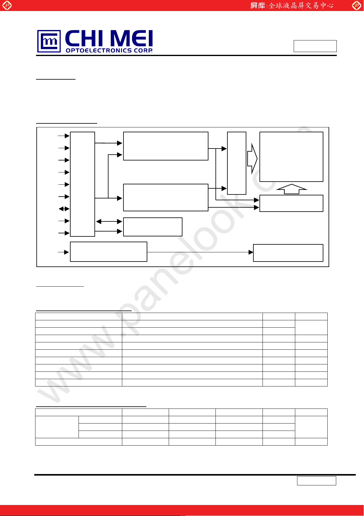
GENERAL DESCRIPTION
OVERVIEW
This product is a 15” TFT Liquid Crystal Display Module with a Backlight unit and 30 pins LVDS (Low Voltage
Differential Signal) interface. This module supports 1024 x 768 XGA mode and can display 262,144 colors. The
inverter module for Backlight is not built in.
BLOCK DIAGRAM
Rxin0(+/-)
Rxin1(+/-)
(JAE-FI-XB30S-HF10)
Rxin2(+/-)
CLK(+/-)
Vcc
INPUT CONNECTOR
GND
Data
EDID
CLK
EDID
V
EDID
www.panelook.com
LVDS INPUT /
TIMING CONTROLLER
DC/DC CONVERTER &
REFERENCE VOLTAGE
GENERATOR
EDID
EEPROM
Issued Date: Apr.19, 2004
Model No. : N150X3-L05
SCAN DRIVER IC
TFT LCD PANEL
(1024xR.G.B.x768)
DATA DRIVER IC
Approval
VL
LAMP CONNECTOR
(JST-BHTR-02VS-1)
BACKLIGHT UNIT
APPLICATION
-Note Book PC
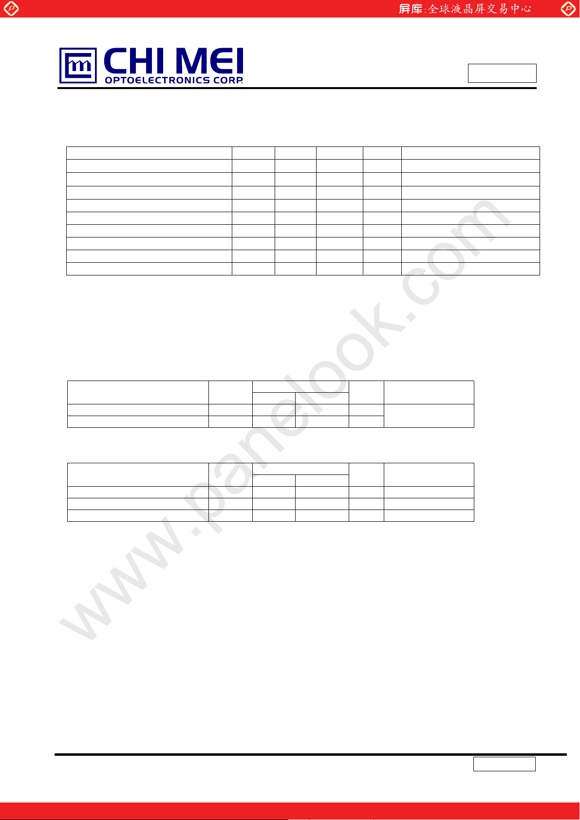
GENERAL SPECIFICATI0NS
Item Specification Unit Note
Active Area 304.1 (H) x 228.1 (V) (15.0” diagonal) mm
Bezel Opening Area 307.8 (H) x 231.6 (V) mm
Driver Element a-si TFT active matrix - Pixel Number 1024 x R.G.B. x 768 pixel Pixel Pitch 0.297 (H) x 0.297 (V) mm Pixel Arrangement RGB vertical stripe - Display Colors 262,144 color Transmissive Mode Normally white - Surface Treatment Hard coating (3H), Anti-glare (Haze 25 %) - -
(1)
MECHANICAL SPECIFICATIONS
Item Min. Typ. Max. Unit Note
Horizontal(H) 316.8 317.3 317.8 mm
Module Size
Note 1: The maximum thickness of I/O connector area is 6.0mm.
Vertical(V) 241.5 242 242.5 mm
Depth(D) 5.4 5.7 6.0 mm
Weight 490 505 520 g -
(1)
4 / 26
One step solution for LCD / PDP / OLED panel application: Datasheet, inventory and accessory!
Version 3.1
www.panelook.com
Global LCD Panel Exchange Center
1. ABSOLUTE MAXIMUM RATINGS
1.1 ABSOLUTE RATING OF ENVIRONMENT
Item Symbol Min. Max. Unit Note
Operating Ambient Temperature TOP 0 +50
Operating Temperature for Panel - 0 +60
Storage Temperature T
Operating Ambient Humidity HOP 20 90 %RH (1)
Storage Humidity H
Air Pressure - 70.0 - kPa Operation
Air Pressure - 12.0 - kPa Non-Operation
Altitude - - 4572 m Operation
Altitude - - 15240 m Non-Operation
Note. (1) Wet bulb temperature should be 39qC Max, and no condensation of water.
www.panelook.com
Issued Date: Apr.19, 2004
Model No. : N150X3-L05
qC
qC
-20 +60
STG
10 90 %RH (1)
STG
qC
Approval
-
(2)
-
(2) The surface temperature caused by self-heat radiation of cell itself is specific on this item.
1.2 ELECTRICAL ABSOLUTE RATINGS
(1) TFT LCD Module
Parameter Symbol
Power supply voltage VCC -0.3 +4.0 V
Logic input voltage VIN -0.3 VCC+0.3 V
(2) Backlight Unit
Parameter Symbol
Lamp voltage VL - 2.5K V
Lamp current IL 1.8 7.0 mA
Lamp frequency fL - 80 KHz -
Note (1) Permanent damage to the device may occur if maximum values are exceeded. Function operation
should be restricted to the conditions described under Normal Operating Conditions.
Value s
Min. Max.
Value s
Min. Max.
Unit Remarks
Ta=0~50ºC
Unit Remarks
RMS
RMS
Note (1)
-
5 / 26
One step solution for LCD / PDP / OLED panel application: Datasheet, inventory and accessory!
Version 3.1
www.panelook.com
Global LCD Panel Exchange Center
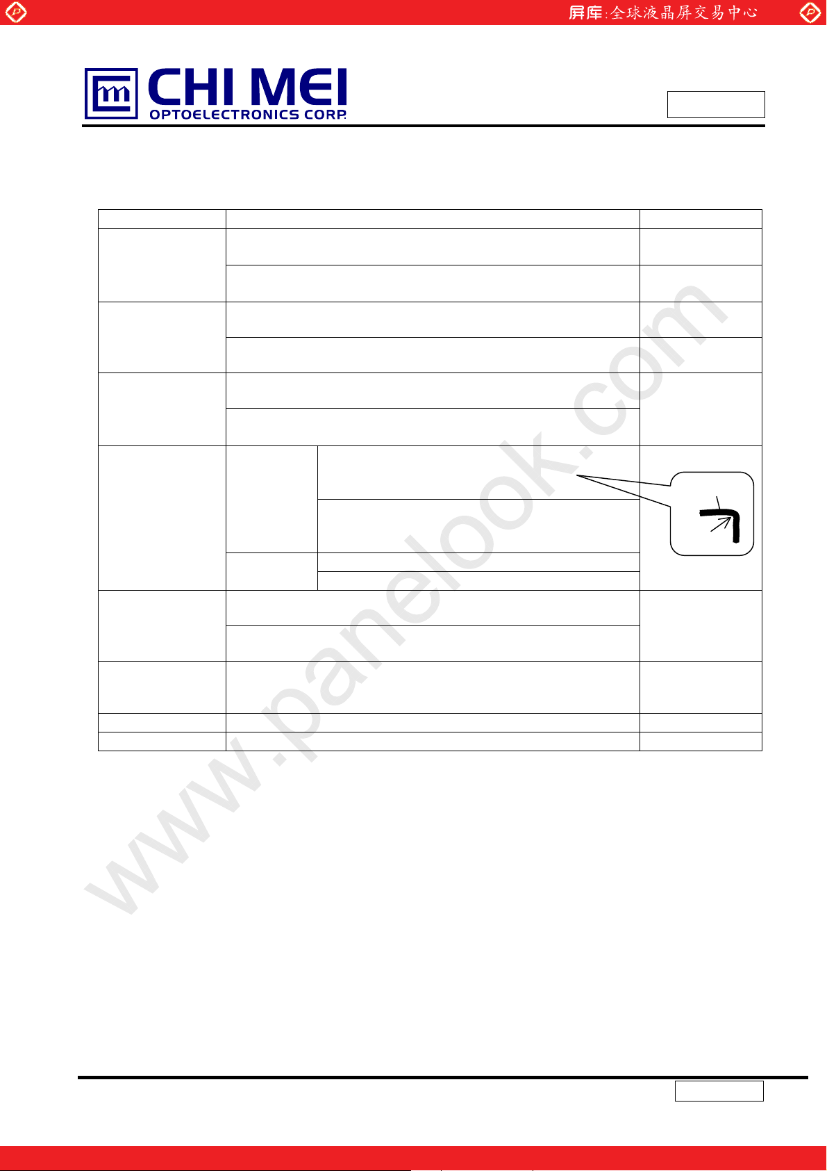
1.3 MECHANICAL RATINGS
LCD shall have no failure in the following reliability items.
Item Test Conditions Note
Frequency Range 5– 500 Hz, 14.7m/s2 (1.5G) constant,
Vibration
Mechanical Shock
Pressure
Resistance
Strength of FL
Cable
Connector tension
test
Assured torque
value at
side-mount part
Re-screwed test 15 times under 245.0 mNm (2.5 kgfcm) Non Operation
Tapping test Test “ Ripple “ Phenomenon. Operation
0.5Hrs each axis (X, Y, Z direction)
Frequency Range 5– 500 Hz, 4.9m/s
0.5Hrs each axis (X, Y, Z direction)
2548m/s2(260G), Pulse width 2ms, Half-Sine Wave, rX, rY, rZ
direction, each 1 time
686m/s
direction, each 3 time
No Destruction with the force 196 N (20 kgf, 16 mm in diameter) to
the display surface at the vertical direction
No Destruction with the force 294.2 N (30 kgf, 30 mm in diameter)
to the back of the display surface at the vertical direction
Strength of
rotation
force
Lead pull
test
Input connector: With 50 times of connector trial there must be no
damage to the shape and functional.
Back light connector: With 50 times of connector trial there must
be no damage to the shape and functional.
294mNm (3.0 kgfcm) Non Operation
www.panelook.com
Model No. : N150X3-L05
2
(0.5G) constant,
2
(70G), Pulse width 11ms, Half-Sine Wave, rX, rY, rZ
Cable: No disconnection of cable to the 5 trial of
360 degree rotation.
See a bent state of cable.
Connector: No disconnection of cable to 10 trial of
180 degree rotation.
See a bent state of cable.
Soldering portion: 14.7N (1.5kgf), 1min
Connector: 14.7N (1.5kgf), 1 sec
Issued Date: Apr.19, 2004
Approval
Non Operation Mechanical
Operation
Operation & Non
Operation
Non Operation
Non Operation
Fig 1-3-1
Fig 1-3-2
Fig 1-3-3
Non Operation
FL
R2
Non Operation
Definitions of failure for judgment shall be as follows:
1) Function of the module should be maintained.
2) Current consumption should be smaller than the specified value.
3) Appearance and display quality should not have distinguished degradation.
4) Luminance should be larger than the minimum value specified in optical specification.
6 / 26
One step solution for LCD / PDP / OLED panel application: Datasheet, inventory and accessory!
Version 3.1
www.panelook.com
Global LCD Panel Exchange Center
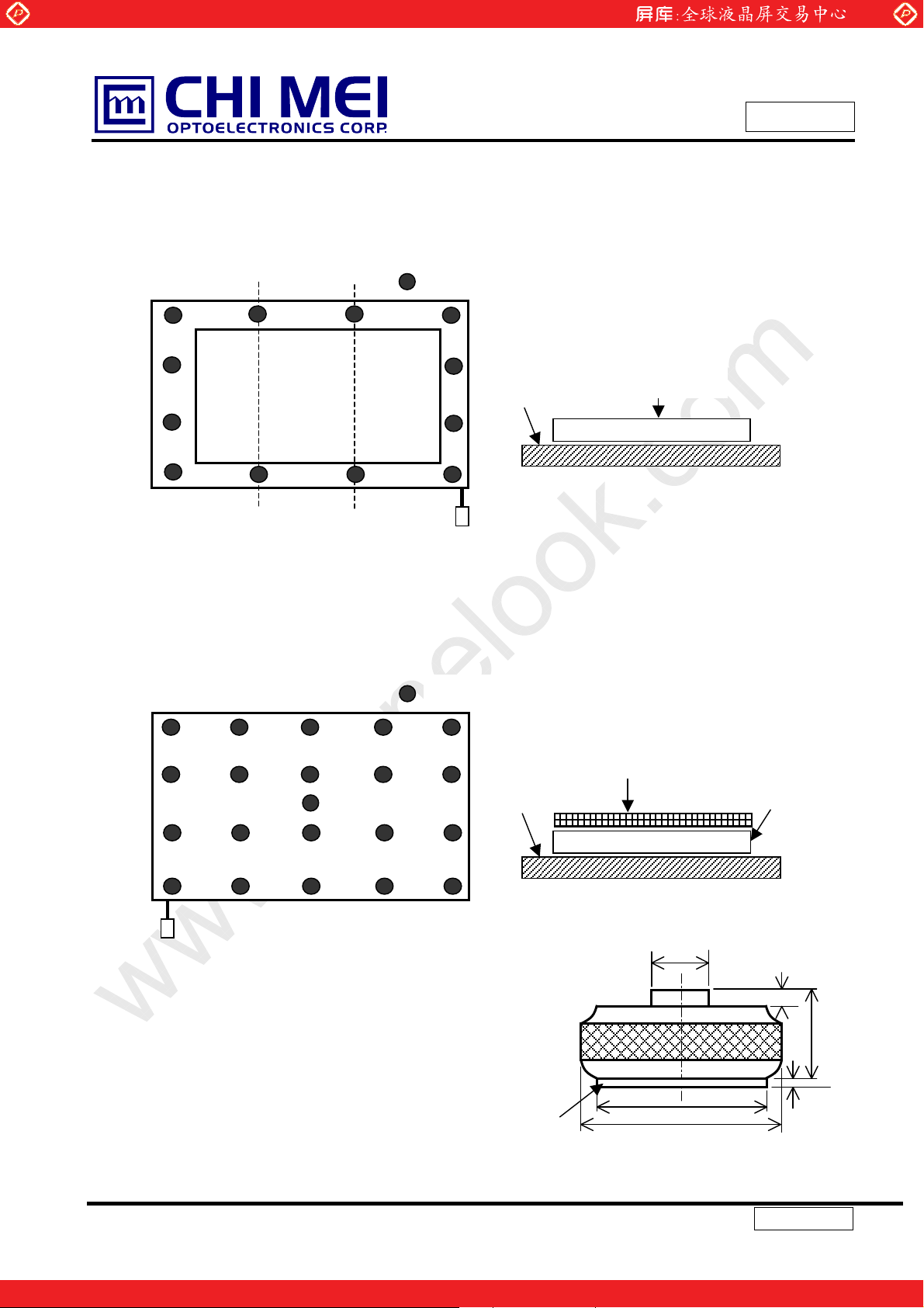
NOTE
(1) The compression condition of front side
(a) Compression point: 12 points ( refer to Fig 1-3-1)
(b) Compression condition: Time 3 sec, Tool diameter: 16 mm in diameter (refer to Fig 1-3-3)
www.panelook.com
Issued Date: Apr.19, 2004
Model No. : N150X3-L05
Approval
: COMPRESSION POINT
Flat plate
Fig 1-3-1
(2) The compression condition of rear side
(a) Compression point: 21 points (refer to Fig 1-3-2 )
(b) Compression condition: Time 3 sec, Tool radius: 30 mm in diameter (refer to Fig 1-3-3)
:COMPRESSION POINT
ABS natural 2.0t
Flat plate
LCD
LCD
Fig 1-3-2
(3) Dimension of the compression jig
(a) compression jig for front side A = 16 mm in diameter
B = 16 mm in diameter
(b) compression jig for rear side A = 30 mm in diameter
B = 28 mm in diameter
(4) Recommend Torque is 1.3 – 1.5 kgf
Rubber sheet
10 mm diameter
B
A
Fig 1-3-3
7 / 26
One step solution for LCD / PDP / OLED panel application: Datasheet, inventory and accessory!
10
16
1.5
Version 3.1
www.panelook.com

Global LCD Panel Exchange Center
1.4 THE OTHERS
(1) Static electricity pressure resistance
Items Testing conditions Operation Non Operation
Contact discharge 150pF, 330 ohm
www.panelook.com
Issued Date: Apr.19, 2004
Model No. : N150X3-L05
Approval
r10 kV r10 kV
Air discharge 150pF, 330 ohm
ESD Acceptance Definition:
Temporary performance degradation. Recovery by operator is acceptable. No hardware failure.
(2) Sound noise
There should be no uncomfortable noise.
Being used under whatever surrounds, when power on/off, the panel should not generate uncomfortable
noise.
(3) Open / Short
No smoke, no firery at any open/ short test
(4) MTBF : 50000 Hr (except for backlight lamp)
r20 kV r20 kV
8 / 26
One step solution for LCD / PDP / OLED panel application: Datasheet, inventory and accessory!
Version 3.1
www.panelook.com
Global LCD Panel Exchange Center
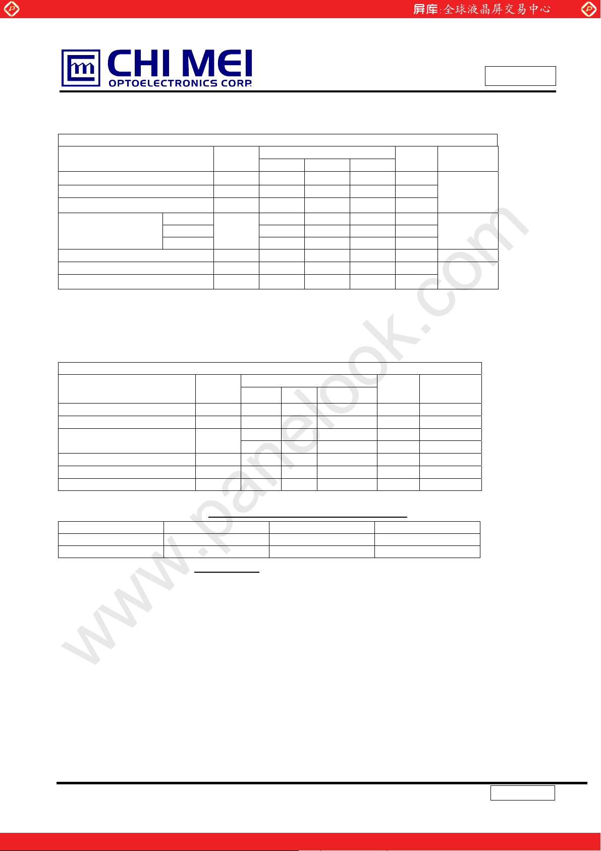
2. ELECTRICAL SPECIFICATIONS
2.1 TFT LCD MODULE
Parameter Symbol
Power Supply Voltage VCC 3.0 3.3 3.6 V
“H” level LVDS signal input VIH - - +100 mV
“L” level LVDS signal input VIL -100 - - mV
White 250 300 350 mA
Power Supply Current
Rush Current I
Ripple voltage VRP - 50 - mV
Terminating resistor Rt - 100 - Ohm
LCD Fuse name: Kamaya(FCC16-162ABTP)
Black 340 400 450 mA
Maximum
www.panelook.com
Issued Date: Apr.19, 2004
Model No. : N150X3-L05
MODULE
Value
Min. Typ. Max.
l
CC
530 580 630 mA
- 1.2 1.5 A (2)
RUSH
Unit Notes
(1)
(9)
(1)
Approval
2.2 BACKLIGHT UNIT
LAMP : Sanken/SS20D3100N6570C2802570S
BACKLIGHT ( 1 Lamp)
Parameter Symbol
Lamp Voltage VL 608 675 743 V
Lamp Current IL 2.0 6.0 6.5 mA (3)
Startup Voltage VS
Operating Frequency FL 40 60 80 KHz (5)
Power Consumption PL - 4.4 - W (6), IL=6.5mA
Lamp Life time LBL 10000 15000 - Hrs (7)
The connector information of Black light unit.
Pin Symbol Description Remark
1 HV Lamp power input Pink
2 LV Ground White
Note (1) Connector PN.: BHTR-02VS-1 or equivalent
Note (2) User’s connector Part No.: SM02B-BHTS-B-TB or equivalent
Min. Typ. Max.
- - 1150 (25oC) V
- - 1500 (0
Value
o
C) V
Unit Notes
IL=6.5mA
RMS
(4)
RMS
(4)
RMS
2.3 MATERIAL LIST CONCERNING EMI REGULATIONS
(1) EMI Regulations:
“N150X3-L05” which is assembled inside Toshiba’s notebook should be met to the regulations as
below:
CISPR: Pub.22 Class B
FCC : Part 15 Class B
VCCI
: Class B
9 / 26
One step solution for LCD / PDP / OLED panel application: Datasheet, inventory and accessory!
Version 3.1
www.panelook.com
 Loading...