

Page 1
Global LCD Panel Exchange Center
www.panelook.com
One step solution for LCD / PDP / OLED panel application: Datasheet, inventory and accessory!
www.panelook.com
Page 2
Global LCD Panel Exchange Center
CONTENTS
REVISION HISTORY
GENERAL DESCRIPTION
1. ABSOLUTE MAXIMUM RATINGS
2. ELECTRICAL SPECIFICATIONS
www.panelook.com
Issue Date: Mar. 01, 2001
Model: N141X203
Approval
3. INTERFACE SPECIFICATIONS
3.1 THE PIN ASSIGNMENT OF INTERFACE CONNECTOR
3.2 INPUT SIGNAL TIMING SPECIFICATIONS
3.3 COLOR DATA INPUT ASSIGNMENT
3.4 POWER UP/DOWN SEQUENCE
4. OPTICAL SPECIFICATIONS
5. MECHNICAL DRAWINGS
6. PRECAUTION
6.1 ASSEMBLY AND HANDLING PRECAUTION
6.2 SAFTY PRECAUTION
7. PACKAGING
7.1 PACKING SPECIFICATIONS
7.2 PACKING METHOD
8. DEFINITION OF SHIPPING LABEL ON MODULE
2/20
Version 3.0
One step solution for LCD / PDP / OLED panel application: Datasheet, inventory and accessory!
www.panelook.com
Page 3
Global LCD Panel Exchange Center
VERSION Date DESCRIPTION
Ver 1.0
Ver 2.0
Apr, 25.00
Apr,26.00
www.panelook.com
Issue Date: Mar. 01, 2001
Model: N141X203
Approval
REVISION HISTORY
Issue Preliminary Specification.
Page 4/20
- To revise “ BLOCK DIAGRAM
- To revise attached Drawing
Ver 2.1
Ver 2.2
Ver 3.0
May.15.00
May.22.00
Mar.01.01
Page 5/20
- To revise “ Operating Frequency “ on ELECTRICAL
SPECIFICATIONS.
Old: 40(Min.)/55(Typ.)/70(Max.) New: 45(Min.)/60(Typ.)/80(Max.)
Page 6/20
- Add “ Measure conditions “ on Note 2.
- To revise Note 3.
Old: Hot(White)/GND(Black) New: Hot(Red)/GND(White)
Page 20/20
- Add “ DEFINITION OF SHIPPING LABEL ON MODULE.
Attached Drawing
- Change attached Drawing from” N14124114A” to “ N14124110A “.
Page 5/20
- Update The connector information of Black light unit.
Old: Pin1 - White / Pin 2 - Black
New: Pin 1 - Red / Pin 2 - White.
Page 13/20
- Update Chromaticity on 4. OPTICAL SPECIFICATIONS.
X
: old: 0.546(Min.)/0.566(Typ.)/0.586(Max.)
R
new: 0.558(Min.)/0.578(Typ.)/0.598(Max.)
Y
: old: 0.308(Min.)/0.328(Typ.)/0.348(Max.)
R
new: 0.311(Min.)/0.331(Typ.)/0.351(Max.)
X
: old: 0.280(Min.)/0.300(Typ.)/0.320(Max.)
G
new: 0.277(Min.)/0.297(Typ.)/0.317(Max.)
Y
: old: 0.547(Min.)/0.567(Typ.)/0.587(Max.)
G
new: 0.550(Min.)/0.570(Typ.)/0.590(Max.)
X
: old: 0.126(Min.)/0.146(Typ.)/0.166(Max.)
B
new: 0.129(Min.)/0.149(Typ.)/0.169(Max.)
Page 16/20
- Update 6. PRECAUTION.
Page 18/20
- Update Figure 7-1 Packing method.
Page 20/20
- Update shipping label.
Attached Drawing
Change Attached Drawing from “N14124110A” to “N14124115A”
3/20
Version 3.0
One step solution for LCD / PDP / OLED panel application: Datasheet, inventory and accessory!
www.panelook.com
Page 4
Global LCD Panel Exchange Center
(
TI
SN75LVDS86A )
GENERAL DESCRIPTION
OVERVIEW
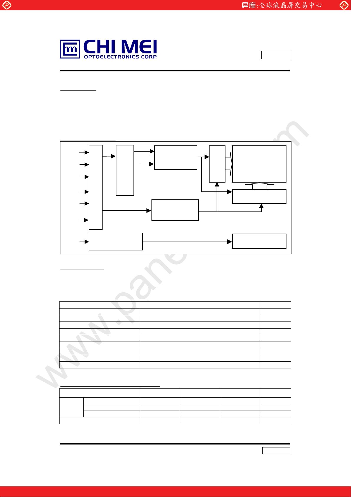
This product is a 14.1” TFT Liquid Crystal Display Module with a Backlight unit and 20 pins
LVDS (Low Voltage Differential Signal) interface. This module supports 1024 x 768 XGA mode
and can display 262,144 colors. The inverter module for Backlight is not built in.
BLOCK DIAGRAM
Rxin0(+/-)
Rxin1(+/-)
Rxin2(+/-)
Input Connector (JAE-FI-SEB20P-HF13R)
www.panelook.com
Issue Date: Mar. 01, 2001
Model: N141X203
Approval
LVDS Receiver
-
Timing Control
ASIC
Scan Driver IC
TFT-LCD Panel
(1024x768x3)
CLK(+/-)
Vcc
Vcc
GND
VL
DC/DC Converter
& Reference
Voltage Generator
Lamp Connector
( JST-BHSR-02VS-1)
Data Driver IC
Backlight Unit
APPLICATION
-Note Book PC
GENERAL SPECIFICATI0NS
Item Specifications Unit
Screen Size 14.1 Diagonal inch
Bezel opening area 288.8(W)x217.4(H) mm
Effective display area 285.7(W)x214.3(H) mm
Pixel number 1024 x R.G.Bx768 pixel
Pixel pitch 0.279(H)x0.279(V) mm
Pixel Arrangement R.G.B Vertical Stripe Display Color 6 bits, 262,144 color
Transmissive mode Normally white Surface treatments Hard coating(3H) and anti-glare -
MECHANICAL SPECIFICATIONS
ITEM MIN. TYP. MAX. Unit
Module
size
One step solution for LCD / PDP / OLED panel application: Datasheet, inventory and accessory!
Horizontal 298 298.5 299 mm
Vertical 227 227.5 228 mm
Depth - 5.8 6.1 mm
Weight - 570 590 g
4/20
Version 3.0
www.panelook.com
Page 5
Global LCD Panel Exchange Center
1. ABSOLUTE MAXIMUM RATINGS
Parameter Symbol
Power supply voltage VCC -0.3 +4.0 V
Logic input voltage VIN -0.3 VCC+0.3 V
Operating temperature Top 0 +50
Storage temperature Tst -20 +60
Note : 90% RH MAX. ( at Ta < 40 к)
Maximum wet-bulb temperature : 39
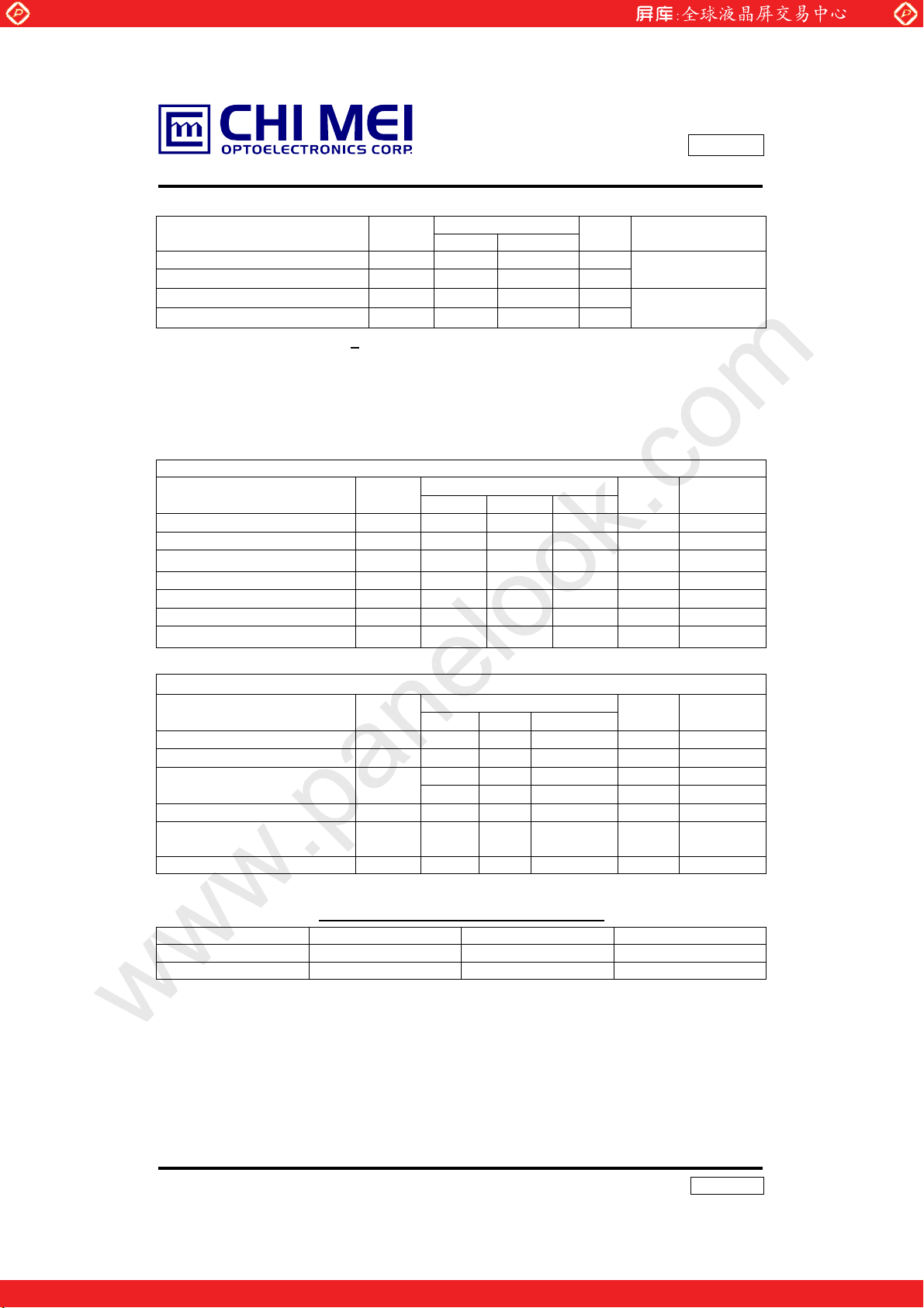
2. ELECTRICAL SPECIFICATIONS
www.panelook.com
Values
Min. Max.
0
C or lower ( at Ta > 40 к)
Issue Date: Mar. 01, 2001
Model: N141X203
Approval
Unit Remarks
Ta = 25 к
к
к
Note
MODULE
Parameter Symbol
Min. Typ. Max.
Valu e
Unit Notes
Power Supply Voltage VCC 3.0 3.3 3.6 V (1)
“H” level LVDS signal input VIH - - +100 mV (1
“L” level LVDS signal input VIL -100 - - mV (1)
Power Supply Current l
Rush Current I
- 400 500 mA (1)
CC
RUSH
- 1.6 1.8 A (1), (2)
Ripple voltage VRP - 50 - mV (1)
Terminating resistor Rt - 100 - Ohm (1)
BACKLIGHT ( 1 Lamp) Ta=252
Parameter Symbol
Min. Typ. Max.
Valu e
Lamp Voltage VL - 700 - V
Unit Notes
IL=6.0mA
RMS
к
Lamp Current IL 2.0 6.0 7.0 mA (3)
Startup Voltage V
S
- 860 1030 (25oC) V
- 1075 1300 (0 oC) V
(4)
RMS
(5)
RMS
Operating Frequency FL 45 60 80 KHz (6)
Power Consumption PL - 4.2 - W
(7),
I
=6.0mA
L
Lamp Life time LBL 10000 15000 - Hrs (8)
The connector information of Black light unit.
Pin Symbol Description Remark
1 HV Lamp power input Red
2 LV Ground White
Connector Part No.: BHSR-02VS-1(JST)
User’s connector Part No.: SM02B-BHSS-1-TB (JST)
Note (1) The operating temperature range is 0 ~ 50 к , and the typical value of Power Supply
Current is measured in black pattern.
5/20
Version 3.0
One step solution for LCD / PDP / OLED panel application: Datasheet, inventory and accessory!
www.panelook.com
Page 6
Global LCD Panel Exchange Center
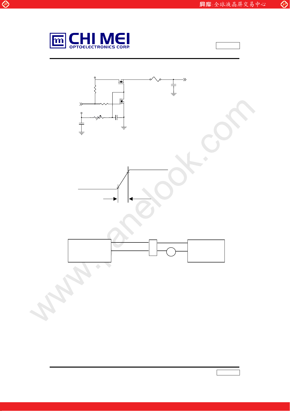
Note (2) Measure conditions
www.panelook.com
Issue Date: Mar. 01, 2001
Model: N141X203
Approval
(High to Low)
(Control Signal)
SW
+12V
C1
1uF
GND
+3.3V
R1
47K
VR1 47K
Q1 2SK1475
0.01uF
Q2
2SK1470
C2
R2
1K
VCC rising time is 470us
0.9VCC
0.1VCC
470us
FUSE
Fig. 1
3.3V
C3
(LCD Modul e Input)
1uF
VCC
Note (3) Lamp current is measured by utilizing a current meter for high frequency as shown
below:
LCD
Module
Hot(Red
GND(White)
)
1
2
A
Inverter
Current meter
Note (4) The voltage shown above should be applied to the lamp for more than 1 second after
startup. Otherwise the lamp may not be turned on.
Note (5) The lamp frequency may produce interference with horizontal synchronous frequency
from the display, and this may cause line flow on the display. In order to avoid
interference the lamp frequency should be detached from the horizontal synchronous
frequency and its harmonics as far as possible.
.
Note (6) P
L
= I
.
V
L
L
6/20
Version 3.0
One step solution for LCD / PDP / OLED panel application: Datasheet, inventory and accessory!
www.panelook.com
Page 7

Global LCD Panel Exchange Center
Note (7) The lifetime (Hr) of a lamp can be defined as the time in which it continues to operate
under the condition Ta = 252
occurs:
(1) When the brightness becomes 50% or lower than its original,
(2) When the effective ignition length becomes 80% or lower than its original value.
(Effective ignition length is defined as an area that has less than 70% brightness
compared to the brightness in the center point.)
Note (8) The waveform of the voltage output of inverter must be area-symmetric and the design
of the inverter must have specifications for the modularized lamp. The performance of
the backlight, such as lifetime or brightness, is greatly influenced by the characteristics
of the DC-AC inverter for the lamp. All the parameters of an inverter should be
designed with care so as not to produce too much current leakage from high-voltage
output of the inverter. When designing or ordering the inverter, please make sure that a
poor lighting caused by the mismatch of the backlight and the inverter (miss-lighting,
flicker, etc.) never occurs. When the above situation is confirmed, the module should
be operated in the same manners as it is installed in your instrument.
www.panelook.com
Issue Date: Mar. 01, 2001
Model: N141X203
Approval
o
C and IL = 6.0 mArms until one of the following event
7/20
Version 3.0
One step solution for LCD / PDP / OLED panel application: Datasheet, inventory and accessory!
www.panelook.com
Page 8

Global LCD Panel Exchange Center
3. INTERFACE SPECIFICATIONS
3.1 THE PIN ASSIGNMENT OF INTERFACE CONNECTOR.
Pin Symbol Description Notes
1 VCC Power supply +3.3 v
2 VCC Power supply +3.3 v
3 Vss Ground
4 Vss Ground
5 Rxin0- LVDS differential data input (Negative)
6 Rxin0+ LVDS differential data input (Positive)
7 Vss Ground
8 Rxin1- LVDS differential data input (Negative)
9 Rxin1+ LVDS differential data input (Positive)
10 Vss Ground
11 Rxin2- LVDS differential data input (Negative)
12 Rxin2+ LVDS differential data input (Positive)
13 Vss Ground
14 CLK- LVDS Clock Data input (Negative)
15 CLK+ LVDS Clock Data input (Negative)
16 Vss Ground
17 NC Non-connection
18 NC Non-connection
19 Vss Ground
20 Vss Ground
Connector Part No.: FI-SEB20P-HF13R (JAE) or Equivalent
User’s connector Part No: FI-S20S or FI-SE20M (JAE)
www.panelook.com
Issue Date: Mar. 01, 2001
Model: N141X203
Approval
R0~R5,G0
G1~G5,B0,B1
B2~B5,DE,Hsync,
Vsync
LVDS level
8/20
Version 3.0
One step solution for LCD / PDP / OLED panel application: Datasheet, inventory and accessory!
www.panelook.com
Page 9

Global LCD Panel Exchange Center
3.2 INPUT SIGNAL TIMING SPECIFICATIONS
The specifications of input signal timing are as the following table and timing diagram.
Signal Parameter Symbol Min Typ Max Unit Remarks
Pixel clock period Tck - 15 - ns
DCLK
DATA
VSYNC
HSYNC
Duty ratio (%Tch) - 40 50 60 % Tch/Tck
Rise time Trck - 4.9 - ns
Fall time Tfck - 4.7 - ns
Setup time Tsd - 4.8 - ns
Hold time Thd - 4.2 - ns
Rise time Trd - 5.5 - ns
Fall time Tfd - 5.5 - ns
Setup time Tsde 3.5 4.0 - ns DE
Hold time Thde 3.5 4.2 - ns
Vertical period Tvp 771 806 812 Thp
Vertical display blank period Tvdb 3 38 44 Thp
Vertical display active period Tvda 768 768 768 Thp
Vertical sync. back porch Vbp 0 29 44 Thp
Vertical sync. front porch Vfp 0 3 43 Thp
Vertical sync. pulse width Vpw 1 6 44 Thp
Horizontal period Thp 1340 1344 1366 Tck
Horizontal display blank period Thdb 178 320 342 Tck
Horizontal display active period Thda 1024 1024 1024 Tck
Horizontal sync. back porch Hbp 0 160 342 Tck
Horizontal sync. front porch Hfb 0 24 319 Tck
Horizontal sync. pulse width Hpw 23 145 342 Tck
www.panelook.com
Issue Date: Mar. 01, 2001
Model: N141X203
Approval
9/20
Version 3.0
One step solution for LCD / PDP / OLED panel application: Datasheet, inventory and accessory!
www.panelook.com
Page 10

Global LCD Panel Exchange Center
VSYNC
HSYNC
www.panelook.com
INPUT SIGNAL TIMING DIAGRAM
pw
V
bp
V
vp
T
vda
vdb
T
T
Issue Date: Mar. 01, 2001
Model: N141X203
Approval
fp
V
DE
HSYNC
DE
DCLK
DATA
768
1
pw
H
2
Hbp
768
Hfp
Thp
hdb
T
Valid display data (1024 Tck)
rck
T
fck
T
hda
T
Invalid Valid
ck
T
ch
T
DCLK
sd
T
hd
T
DATA
rd / Tfd
T
Tsde
Thde
DE
10/20
Version 3.0
One step solution for LCD / PDP / OLED panel application: Datasheet, inventory and accessory!
90%
10%
90%
10%
90%
www.panelook.com
Page 11

Global LCD Panel Exchange Center
3.3 COLOR DATA INPUT ASSIGNMENT
www.panelook.com
Issue Date: Mar. 01, 2001
Model: N141X203
Approval
Basic
Colors
Gray
Scale
Of
Red
Gray
Scale
Of
Green
Gray
Scale
Of
Blue
Color
Black
Red
Green
Blue
Cyan
Magenta
Yellow
White
Red(0) / Dark
Red(1)
Red(2)
:
:
Red(61)
Red(62)
Red(63)
Green(0) / Dark
Green(1)
Green(2)
:
:
Green(61)
Green(62)
Green(63)
Blue(0) / Dark
Blue(1)
Blue(2)
:
:
Blue(61)
Blue(62)
Blue(63)
Data Signal
R5 R4 R3 R2 R1 R0 G5 G4 G3 G2 G1 G0 B5 B4 B3 B2 B1 B0
0
1
0
0
0
1
1
1
0
0
0
:
:
1
1
1
0
0
0
:
:
0
0
0
0
0
0
:
:
0
0
0
Red Green Blue
0
0
1
0
0
0
1
1
1
0
0
0
:
:
1
1
1
0
0
0
:
:
0
0
0
0
0
0
:
:
0
0
0
0
0
0
0
0
0
0
0
0
0
0
1
1
1
1
0
0
0
1
1
1
1
1
1
0
0
0
0
1
1
1
0
0
0
0
0
0
0
0
0
0
1
1
1
1
1
1
1
1
1
0
0
0
0
1
1
1
0
0
0
0
0
0
1
1
1
1
0
0
0
1
1
1
1
1
1
1
1
1
1
1
1
1
1
1
1
1
1
1
1
1
0
0
0
0
0
0
0
0
0
:
:
1
1
1
0
0
0
:
:
0
0
0
0
0
0
:
:
0
0
0
0
0
0
0
0
0
0
1
0
0
0
0
0
0
0
0
1
0
:
:
:
:
:
:
:
:
:
:
:
:
:
:
:
:
0
0
0
0
0
1
0
1
0
0
0
0
0
1
1
0
0
0
:
:
0
0
0
0
0
0
:
:
0
0
0
0
1
0
0
0
0
0
1
1
0
0
0
0
0
0
0
0
0
0
0
0
0
0
0
:
:
:
:
:
:
:
:
:
:
0
0
1
1
1
0
0
1
1
1
0
0
1
1
1
0
0
0
0
0
0
0
0
0
0
0
0
0
0
0
:
:
:
:
:
:
:
:
:
:
0
0
0
0
0
0
0
0
0
0
0
0
0
0
0
0
0
0
0
1
0
:
:
:
:
0
1
1
1
1
1
0
0
0
0
0
0
:
:
:
:
0
0
0
0
0
0
1
0
0
0
0
0
0
:
:
:
:
0
0
0
0
0
0
0
0
1
0
0
0
:
:
:
:
1
0
0
0
1
0
0
0
0
0
0
0
:
:
:
:
1
0
1
0
1
0
1
0
0
0
0
0
0
:
:
:
:
0
0
0
0
0
0
0
0
0
0
0
0
:
:
:
:
0
0
0
0
0
0
0
0
0
0
0
0
:
:
:
:
1
1
1
1
1
1
0
0
0
0
0
0
0
0
0
0
0
0
0
0
0
0
1
1
1
0
1
0
0
0
:
:
0
0
0
0
0
0
:
:
0
0
0
0
0
0
:
:
1
1
1
0
0
0
1
1
1
1
1
1
0
0
1
1
0
0
0
0
0
0
:
:
:
:
0
0
0
0
0
0
0
0
0
0
0
0
:
:
:
:
0
0
0
0
0
0
0
0
1
0
0
1
:
:
:
:
1
0
0
1
1
1
11/20
Version 3.0
One step solution for LCD / PDP / OLED panel application: Datasheet, inventory and accessory!
www.panelook.com
Page 12

Global LCD Panel Exchange Center
3.4 POWER UP/DOWN SEQUENCE
www.panelook.com
Issue Date: Mar. 01, 2001
Model: N141X203
Approval
10%
t4
10%
Vcc
0V
Signals
0V
10%
90%
t1
t2
t5
90%
t3
t6
CCFL
Timing Specifications:
0 ≤ t1 ≤ 10mS
0 ≤ t2 ≤ 50mS
0 ≤ t3 ≤ 50mS
t4 ≥1S
t5 ≥ 170mS
t6 ≥ 200mS (min.)
Notes: 1. Please avoid floating state of interface signal at invalid period.
2. When the interface signal is invalid, be sure to pull down the power supply for
LCD Vcc to 0V.
12/20
Version 3.0
One step solution for LCD / PDP / OLED panel application: Datasheet, inventory and accessory!
www.panelook.com
Page 13

Global LCD Panel Exchange Center
4. OPTICAL SPECIFICATIONS
The following optical specifications shall be measured in a dark room or equivalent state
(ambient luminance ≤1 lux, and at room temperature). The measurement must be taken after
backlight warming up for 20 minutes. The operation temperature is 25
measurement method is shown in Note (1).
Parameter Symbol Condition Min. Typ. Max. Unit Note
Central Luminance L Center,I
Contrast ratio CR Center 150 200 - - (1), (3)
Horizontal
Viewing Angle
Ver tical
Average Luminance L
Brightness Uniformity Buni
Response Time
Chromaticity
Rising TR - 15 30 ms
Falling T
www.panelook.com
Issue Date: Mar. 01, 2001
Model: N141X203
Approval
° к ± 2к
=6.0mA 120 150 - cd/m
L
θx+
Center
θ
x-
CR ≥10
θy+
θ
y-
IL = 6.0mA 110 140 - cd/m2 (1), (5)
AVE
F
θx = θy = 0
Center
θ
x = θy = 0
o
o
40 45 50
40 45 50
10 15 20
degree (1), (4)
30 35 40
1.0 1.4 1.6 (1), (6)
- 35 50 ms
Xw 0.290 0.310 0.330
Yw 0.310 0.330 0.350
XR 0.558 0.578 0.598
Center
YR 0.311 0.331 0.351
θ
XG 0.277 0.297 0.317
x = θy = 0
o
YG 0.550 0.570 0.590
XB 0.129 0.149 0.169
Y
B
0.104 0.124 0.144
(1), (2),
2
. The
(4)
(1), (7)
(1), (8)
Note (1) The method of optical measurement:
Field=2
º
Photodetector
(TOPCON BM-5A)
50cm
TFT-LCD Module
13/20
Version 3.0
One step solution for LCD / PDP / OLED panel application: Datasheet, inventory and accessory!
www.panelook.com
Page 14

Global LCD Panel Exchange Center
Note (2) Definition of Central Luminance (L):
Central Luminance must be measured at the central point of the LCD module and at the
viewing angle of the θx = θy = 0
Note (3) Definition of Contrast Ratio (CR):
Contrast ratio measurement must be made at the viewing angle of the θx = θy = 0
and at the central point of the LCD module. The Luminance (Note 2) shall be measured with all
pixels in the viewing field set initially to be white state, then black state.
www.panelook.com
o
(Note 4).
Issue Date: Mar. 01, 2001
Model: N141X203
Approval
o
(Note 4)
Luminance with all pixels in white state
CR =
Luminance with all pixels in black state
Note (4) Definitions of Viewing Angle (CR ≥ 10):
Normal
θx = θy = 0º
θy- θy+
θX-
= 90º
6 o’clock
y- = 90º
θ
x-
y-
θx−
θx+
12 o’clock direction
y+
θ
y+
= 90º
x+
θX+ = 90º
Note (5) Definition of Average Luminance:
The Average Luminance is defined as arithmetic mean value of five spots across the LCD
surface at white state. The Luminance (Note 2) shall be measured with all pixels in the viewing
field at white state. The measuring spots must be taken at the locations shown in the following
figure, where a = b = 15mm.
L
AVE
L1 + L2 + L3 + L4 + L5
=
5
14/20
Version 3.0
One step solution for LCD / PDP / OLED panel application: Datasheet, inventory and accessory!
www.panelook.com
Page 15

Global LCD Panel Exchange Center
www.panelook.com
Issue Date: Mar. 01, 2001
Model: N141X203
Approval
Luminance Measuring Points
D/4
b
D/2 3D/4
b
a
W
1
5
3
2
4
a
b
b
D
Note (6) Definition of Brightness Uniformity (B
uni
):
Maximum luminance of 5 points
(Note 5).
Note (7) Definition of Response Time:
The Response Time is set initially by defining the “ Rising Time (T
Time (T
Buni=
Minimum luminance of 5 points
)” respectively. TR and TF are defined as following figure.
F
a
W/4
W/2
3W/4
a
)” and the “ Falling
R
Data input
100%
90%
10%
0%
T
R
15/20
White BlackWhite
T
F
Version 3.0
One step solution for LCD / PDP / OLED panel application: Datasheet, inventory and accessory!
www.panelook.com
Page 16

Global LCD Panel Exchange Center
Note (8) Definition of Chromaticity:
The color coordinates (Xw, Yw), (X
in the viewing field at white, red, green, and blue states, respectively.
5. MECHNICAL DRAWING
Please refer to the attached drawings.
6. PRECAUTION
6. 1 ASSEMBLY AND HANDLING PRECAUTION
(1) Do not apply rough force such as bending or twisting to the module during assembly.
(2) To assemble or install module into user’s system can be only in clean working areas. The
dust and oil may cause electrical short or worsen the polarizer.
(3) It’s not permitted to have pressure or impulse on the module because the LCD panel and
backlight will be damaged.
(4) Always follow the correct power sequence when LCD module is connecting and operating.
This can prevent damage to the CMOS LSI chips during latchup.
(5) Do not pull the I/F connector in or out while the module is operating.
(6) Do not disassemble the module.
(7) Use a soft dry cloth without chemicals for cleaning, because the surface of polarizer is very
soft and easily scratched.
(8) It is dangerous that moisture come into or contacted the LCD module, because moisture
may damage LCD module when it is operating.
(9) High temperature or humidity may reduce the performance of module. Please store LCD
module within the specified storage conditions.
(10) When ambient temperature is lower than 10ºC may reduce the display quality. For example,
the response time will become slowly, and the starting voltage of CCFL will be higher than
room temperature.
www.panelook.com
R,YR
), (XG,YG), and (XB,YB) are obtained with all pixels
Issue Date: Mar. 01, 2001
Model: N141X203
Approval
6.2 SAFTY PRECAUTION
(1) The startup voltage of backlight is approximately 1000 Volts. It may cause electrical shock
while assembling with inverter. Do not disassemble the module or insert anything into the
backlight unit.
(2) If the liquid crystal material leaks from the panel, it should be kept away from the eyes or
mouth. In case of contact with hands, skin or clothes, it has to be washed away thoroughly
with soap.
16/20
Version 3.0
One step solution for LCD / PDP / OLED panel application: Datasheet, inventory and accessory!
www.panelook.com
Page 17

Global LCD Panel Exchange Center
www.panelook.com
Issue Date: Mar. 01, 2001
Model: N141X203
Approval
Figure 6.1 : Mounting Screw Method
17/20
Version 3.0
One step solution for LCD / PDP / OLED panel application: Datasheet, inventory and accessory!
www.panelook.com
Page 18

Global LCD Panel Exchange Center
7. PACKAGING
7.1 PACKING SPECIFICATIONS
(1) 10 LCD modules / 1 Box
(2) Box dimensions : 422(L) X 337(W) X 345(H) mm
(3) Weight : approximately 7.0Kg (10 modules per box)
7.2 PACKING Method
www.panelook.com
Issue Date: Mar. 01, 2001
Model: N141X203
Approval
The Figure. 7-1, 2 show the packing method.
Figure. 7-1 Packing method
18/20
Version 3.0
One step solution for LCD / PDP / OLED panel application: Datasheet, inventory and accessory!
www.panelook.com
Page 19

Global LCD Panel Exchange Center
www.panelook.com
Issue Date: Mar. 01, 2001
Model: N141X203
Approval
Figure. 7-2 Packing method
19/20
Version 3.0
One step solution for LCD / PDP / OLED panel application: Datasheet, inventory and accessory!
www.panelook.com
Page 20

Global LCD Panel Exchange Center
N
8. DEFINITION OF SHIPPING LABEL ON MODULE
The barcode nameplate is pasted on each module as illustration, and its
efinitions are as following explanation.
www.panelook.com
Issue Date: Mar. 01, 2001
Model: N141X203
Approval
CHI MEI
OPTOELECTRONICS
0 4 C 1 0 3 2 0 3 9 1 0 0 0 1
(1) Model Name : N141X203
(2) Revision : Rev.XX, for example : C1, C2 …etc.
(3) Serial ID Example : 0 4
1 4 1 X 2 0 3 Rev. XX
0 4 C 1 0 3 1 0 3 9 1 0 0 0 1
MADE IN TAIWAN
MADE IN TAIWAN
MADE IN TAIWAN
C 1 0 3 2 0 3 9 1 0 0 0 1
Serial No.
Product Line
Year, Month, Date
CMO Internal Use
Revision
Serial ID include the information as list.
1. Manufactured Date : Year : 0~9, for 2000~2009
Month : 1~9, A~C, for Jan. ~ Dec.
Day : 1~9, A~Y, for 1
st
to 31th, exclude I and O and U
2. Revision Code : cover all the change
3. Model code
4. Serial No. : Manufacturing sequence of product
5. Product Line : 1 -> Line1, 2 -> Line 2 …,etc.
20/20
Model Code
Version 3.0
One step solution for LCD / PDP / OLED panel application: Datasheet, inventory and accessory!
www.panelook.com
Page 21

Global LCD Panel Exchange Center
www.panelook.com
One step solution for LCD / PDP / OLED panel application: Datasheet, inventory and accessory!
www.panelook.com
Page 22

Global LCD Panel Exchange Center
www.panelook.com
Model: N141X203
E207943
Reating: 3.3Vdc 400mA
One step solution for LCD / PDP / OLED panel application: Datasheet, inventory and accessory!
www.panelook.com
 Loading...