

Page 1
Global LCD Panel Exchange Center
TFT LCD Preliminary Specification
MODEL NO.: M216H1-L07
www.panelook.com
Issued Date: Jul,14,2009
Model No.: M216H1-L07
Preliminary
Customer :
Approved by :
Note :
1 / 28
Version 1.0
One step solution for LCD / PDP / OLED panel application: Datasheet, inventory and accessory!
www.panelook.com
Page 2
Global LCD Panel Exchange Center
www.panelook.com
Issued Date: Jul,14,2009
Model No.: M216H1-L07
Preliminary
- CONTENTS -
REVISION HISTORY
1. GENERAL DESCRIPTION
1.1 OVERVIEW
1.2 FEATURES
1.3 APPLICATION
1.4 GENERAL SPECIFICATIONS
1.5 MECHANICAL SPECIFICATIONS
2. ABSOLUTE MAXIMUM RATINGS
2.1 ABSOLUTE RATINGS OF ENVIRONMENT
2.2 ELECTRICAL ABSOLUTE RATINGS
2.2.1 TFT LCD MODULE
2.2.2 BACKLIGHT UNIT
3. ELECTRICAL CHARACTERISTICS
3.1 TFT LCD MODULE
3.1. 1 Vcc POWER DIP CONDITION
3.2 BACKLIGHT UNIT
4. BLOCK DIAGRAM
4.1 TFT LCD MODULE
4.2 BACKLIGHT UNIT
5. INPUT TERMINAL PIN ASSIGNMENT
5.1 TFT LCD MODULE
5.2 LVDS DATA MAPPING TABLE
5.3 BACKLIGHT UNIT
5.4 COLOR DATA INPUT ASSIGNMENT
6. INTERFACE TIMING
6.1 INPUT SIGNAL TIMING SPECIFICATIONS
6.2 POWER ON/OFF SEQUENCE
7. OPTICAL CHARACTERISTICS
7.1 TEST CONDITIONS
7.2 OPTICAL SPECIFICATIONS
8. PACKAGING ------------------------------------------------------- 22
8.1 PACKING SPECIFICATIONS
8.2 PACKING METHOD
------------------------------------------------------- 4
------------------------------------------------------- 5
------------------------------------------------------- 6
------------------------------------------------------- 8
------------------------------------------------------- 12
------------------------------------------------------- 13
------------------------------------------------------- 16
------------------------------------------------------- 19
9. DEFINITION OF LABELS
9.1 CMO MODULE LABEL
------------------------------------------------------- 24
10.RELIABILITY TEST
------------------------------------------------------- 25
2 / 28
Version 1.0
One step solution for LCD / PDP / OLED panel application: Datasheet, inventory and accessory!
www.panelook.com
Page 3
Global LCD Panel Exchange Center
www.panelook.com
Issued Date: Jul,14,2009
Model No.: M216H1-L07
Preliminary
11. PRECAUTIONS ------------------------------------------------------- 25
11.1 ASSEMBLY AND HANDLING PRECAUTIONS
11.2 SAFETY PRECAUTIONS
11.3 SAFETY STANDARDS
11.4 STORAGE
11.5 OPERATION CONDITION GUIDE
11.6 OTHER
12. MECHANICAL CHARACTERISTICS ------------------------------------------------------- 27
3 / 28
Version 1.0
One step solution for LCD / PDP / OLED panel application: Datasheet, inventory and accessory!
www.panelook.com
Page 4
Global LCD Panel Exchange Center
www.panelook.com
REVISION HISTORY
Version Date Section Description
Issued Date: Jul,14,2009
Model No.: M216H1-L07
Preliminary
Ver 1.0
Jul. 14, ‘09
All M216H1-L07 Specifications was first issuedΖ
4 / 28
Version 1.0
One step solution for LCD / PDP / OLED panel application: Datasheet, inventory and accessory!
www.panelook.com
Page 5
Global LCD Panel Exchange Center
1. GENERAL DESCRIPTION
1.1 OVERVIEW
The M216H1-L07 model is a 21.6 inch wide TFT-LCD module with a 2-CCFL Backlight Unit and a
30-pin 2ch-LVDS interface. This module supports 1920 x 1080 Full HD (16:9 wide screen) mode and
displays up to 16.7 millions colors. The inverter module for the Backlight Unit is not built in.
1.2 FEATURES
- Super wide viewing angle
- High contrast ratio
- Fast response time
- High color saturation (EBU Like Specifications)
- FULL HD(1920 x 1080 pixels) resolution
- DE (Data Enable) only mode
www.panelook.com
Issued Date: Jul,14,2009
Model No.: M216H1-L07
Preliminary
- LVDS (Low Voltage Differential Signaling) interface
- RoHS compliance.
1.3 APPLICATION
- Workstation & desktop monitor
- Display terminals for AV application
1.4 GENERAL SPECIFICATI0NS
Item Specification Unit Note
Diagonal size 547.863 mm
Active Area 477.504 x 268.596 mm
Bezel Opening Area 481.5 (H) x 272.6 (V) mm
Driver Element a-Si TFT active matrix - Pixel Number 1920 x R.G.B. x 1080 pixel Pixel Pitch 0.248(H) x 0.248(V) mm Pixel Arrangement RGB vertical stripe - Display Colors 16.7 millions color Transmissive Mode Normally White - Surface Treatment Hard coating (3H), AG (Haze 25%) - Module Power Consumption 19.2 Watt (2)
(1)
1.5 MECHANICAL SPECIFICATIONS
Item Min. Typ. Max. Unit Note
Horizontal(H) 499 499.5 500 mm
Module Size
I/F connector mounting
Note (1) Please refer to the attached drawings for more information of front and back outline dimensions.
Note (2) Please refer to sec. 3.1 & 3.2 in this document for more information of power consumption.
Vertical(V) 292.1 292.6 293.1 mm
Depth(D) 12.5 13 13.5 mm
Weight - 1980 2030 g
position
The mounting inclination of the connector makes
the screen center within ±0.5 mm as the horizontal.
5 / 28
Version 1.0
One step solution for LCD / PDP / OLED panel application: Datasheet, inventory and accessory!
(1)
www.panelook.com
Page 6
Global LCD Panel Exchange Center
A
2. ABSOLUTE MAXIMUM RATINGS
2.1 ABSOLUTE RATINGS OF ENVIRONMENT
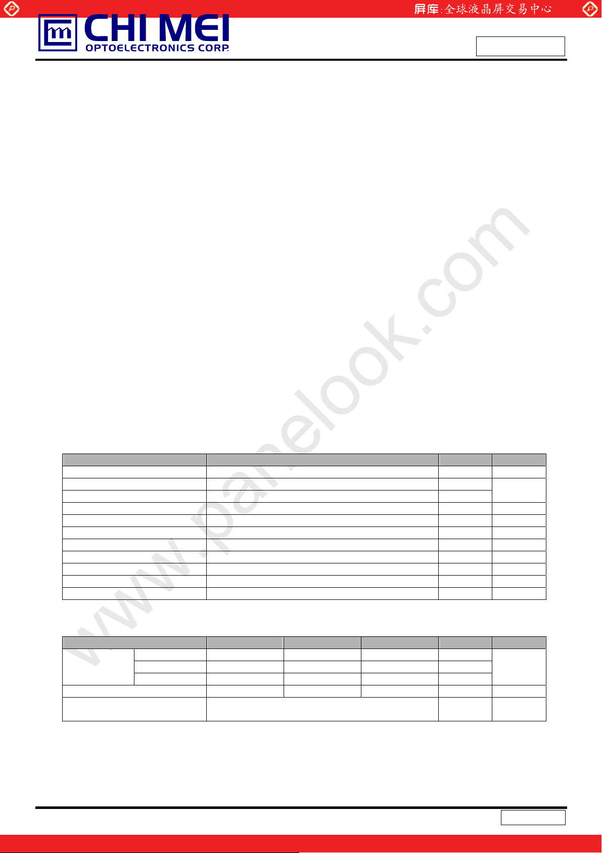
Item Symbol
Storage Temperature T
Operating Ambient Temperature T
Shock (Non-Operating) S
Vibration (Non-Operating) V
LCD Cell Life Time L
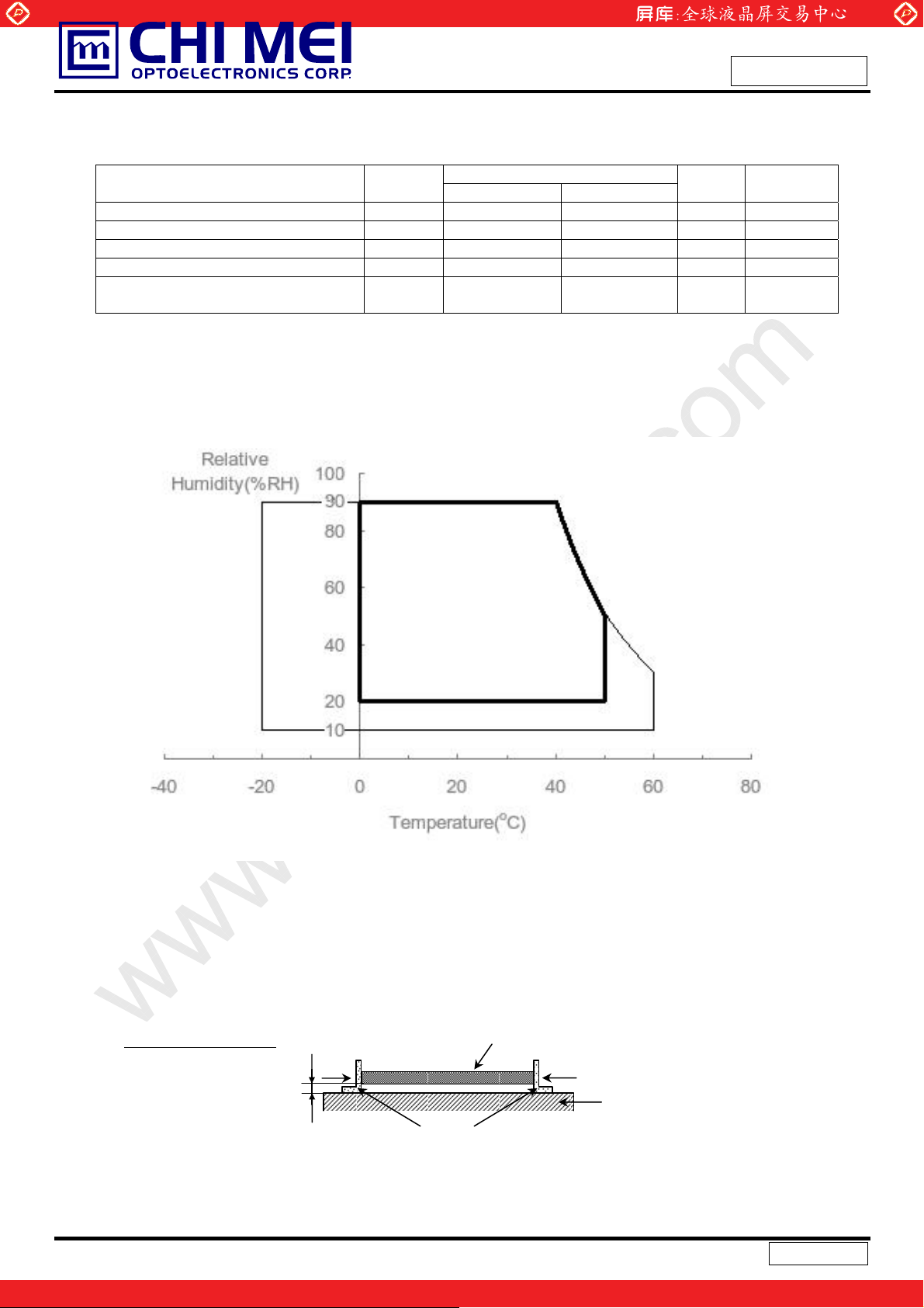
Note (1) Temperature and relative humidity range is shown in the figure below.
www.panelook.com
Value
Min. Max.
ST
OP
NOP
NOP
CELL
-20 +60 ºC (1)
0 +50 ºC (1), (2)
- 50 G (3), (5)
- 1.5 G (4), (5)
50,000 - Hrs
Issued Date: Jul,14,2009
Model No.: M216H1-L07
Preliminary
Unit Note
MTBF
based
(a) 90% RH Max. (Ta Љ
(b) Wet-bulb temperature should be 39 ºC Max. (Ta > 40 ºC).
40
(c) No condensation.
ºC).
Note (2) The temperature of panel surface should be 0 ºC Min. and 60 ºC Max.
Note (3) 50G,11 ms, half-sine wave, 1 time for ± X, ± Y, ± Z.
Note (4) 10 ~ 300 Hz, sweep rate 10 min / cycle , 30 min for X,Y,Z axis
Note (5) Upon the Vibration and Shock tests, the fixture use
d to hold the module must be firm and rigid
enough to prevent the module from twisting or bending by the fixture.
t Room Temperature
Side Mount Fixing Screw
LCD Module
Side Mount Fixing Screw
Stage
Gap=3~5mm
Bracket
6 / 28
Version 1.0
One step solution for LCD / PDP / OLED panel application: Datasheet, inventory and accessory!
www.panelook.com
Page 7
Global LCD Panel Exchange Center
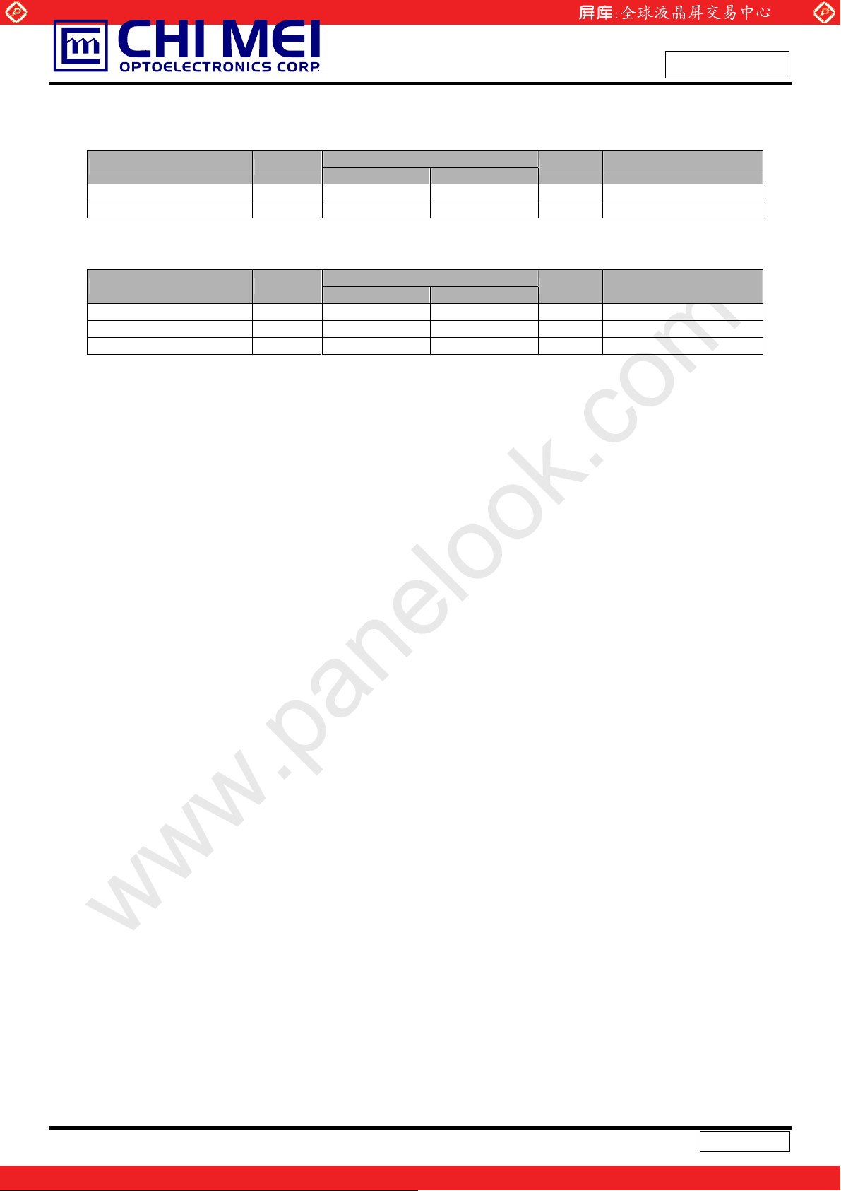
2.2 ELECTRICAL ABSOLUTE RATINGS
2.2.1 TFT LCD MODULE
Item Symbol
Power Supply Voltage Vcc -0.3 +6.0 V (1)
Logic Input Voltage Vlogic +3.0 +3.6 V
2.2.2 BACKLIGHT UNIT
Item Symbol
Lamp Voltage V
Lamp Current I
Lamp Frequency F
Note (1) Permanent damage to the device may occur if maximum values are exceeded. Function
operation should be restricted to the conditions described under Normal Operating Conditions.
Note (2) Specified values are for lamp (Refer to 3.2 for further information).
L
L
L
www.panelook.com
Issued Date: Jul,14,2009
Model No.: M216H1-L07
Preliminary
Value
Min. Max.
Value
Min. Max.
- 2500 V
3.0 8.0 mA
40 80 KHz (1), (2)
Unit Note
Unit Note
RMS
RMS
(1), (2), IL = 7.5 mA
(1), (2)
7 / 28
Version 1.0
One step solution for LCD / PDP / OLED panel application: Datasheet, inventory and accessory!
www.panelook.com
Page 8
Global LCD Panel Exchange Center
www.panelook.com
Issued Date: Jul,14,2009
Model No.: M216H1-L07
3. ELECTRICAL CHARACTERISTICS
3.1 TFT LCD MODULE Ta = 25 ± 2 ºC
Parameter Symbol
Min. Typ. Max.
Power Supply Voltage Vcc 4.5 5.0 5.5 V Ripple Voltage V
Rush Current I
RP
RUSH
- -- 300 mV -
- -- 3.0 A (2)
White - 0.73 0.95 A (3)a
Power Supply Current
Black
Vertical Stripe
Power consumption (without Backlight Unit) Plcd
lcc
-
-
-
LVDS differential input voltage Vid 100 - 600 mV
LVDS common input voltage Vic 1.0 1.2 1.4 V
Logic High Input Voltage VIH 2.64 -- 3.6 V
Logic Low Input Voltage VIL 0 -- 0.66 V
Note (1) The module should be always operated within above ranges.
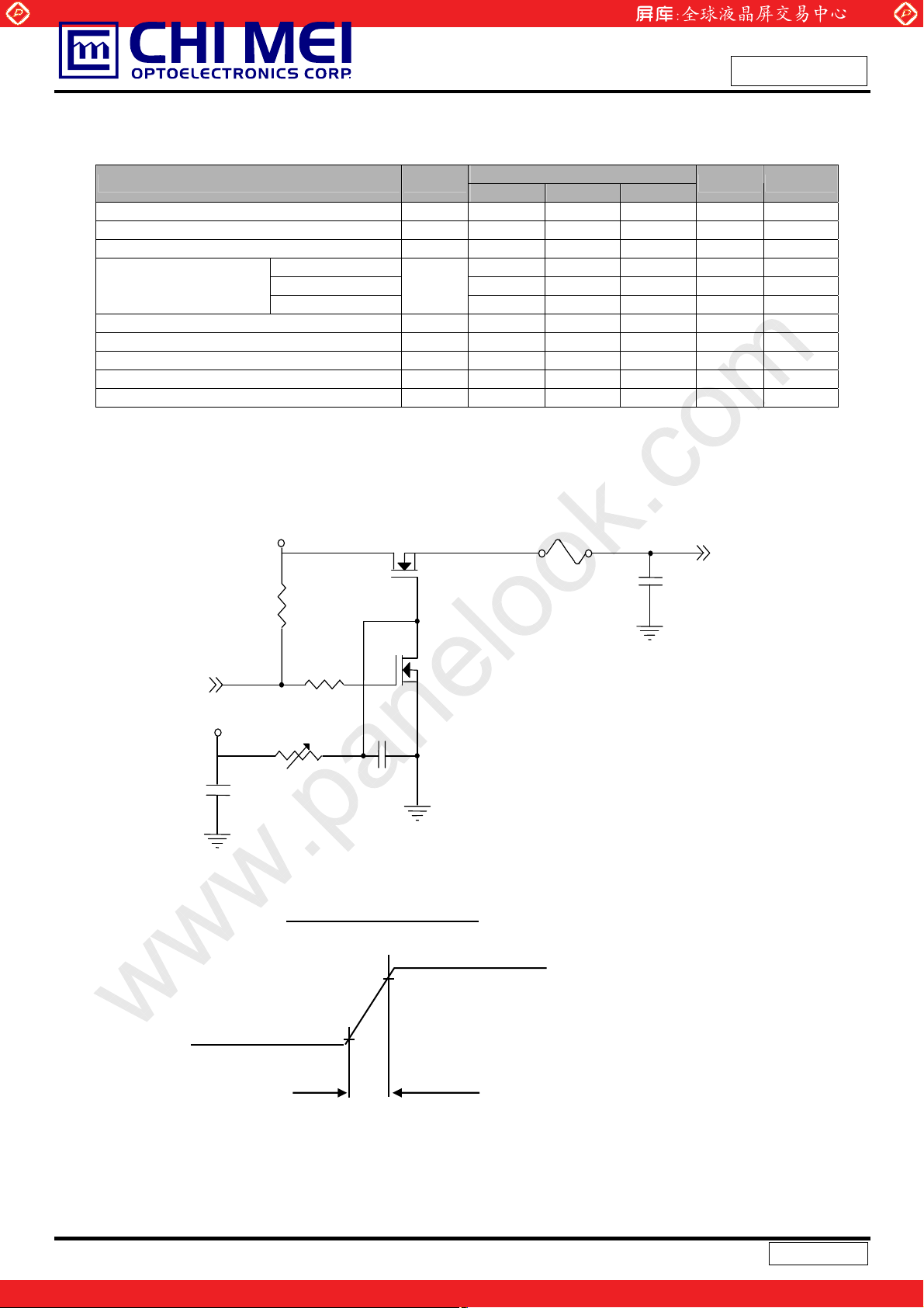
Note (2) Power on rush current measurement conditions:
Value
Unit Note
1.26 1.65 A (3)b
1.22 1.6 A (3)c
6.3 8.25 Watt (4)
Preliminary
+5.0V
R1
47K
Q1 2SK1475
FUSE
C3
1uF
Vcc
(LCD Module Input)
(High to Low)
(Control Signal)
SW
+12V
C1
1uF
VR1
R2
1K
47K
0.01uF
Q2
2SK1470
C2
Vcc rising time is 470Ps
Vcc
0.9Vcc
0.1
GND
470Ps
8 / 28
Version 1.0
One step solution for LCD / PDP / OLED panel application: Datasheet, inventory and accessory!
www.panelook.com
Page 9
Global LCD Panel Exchange Center
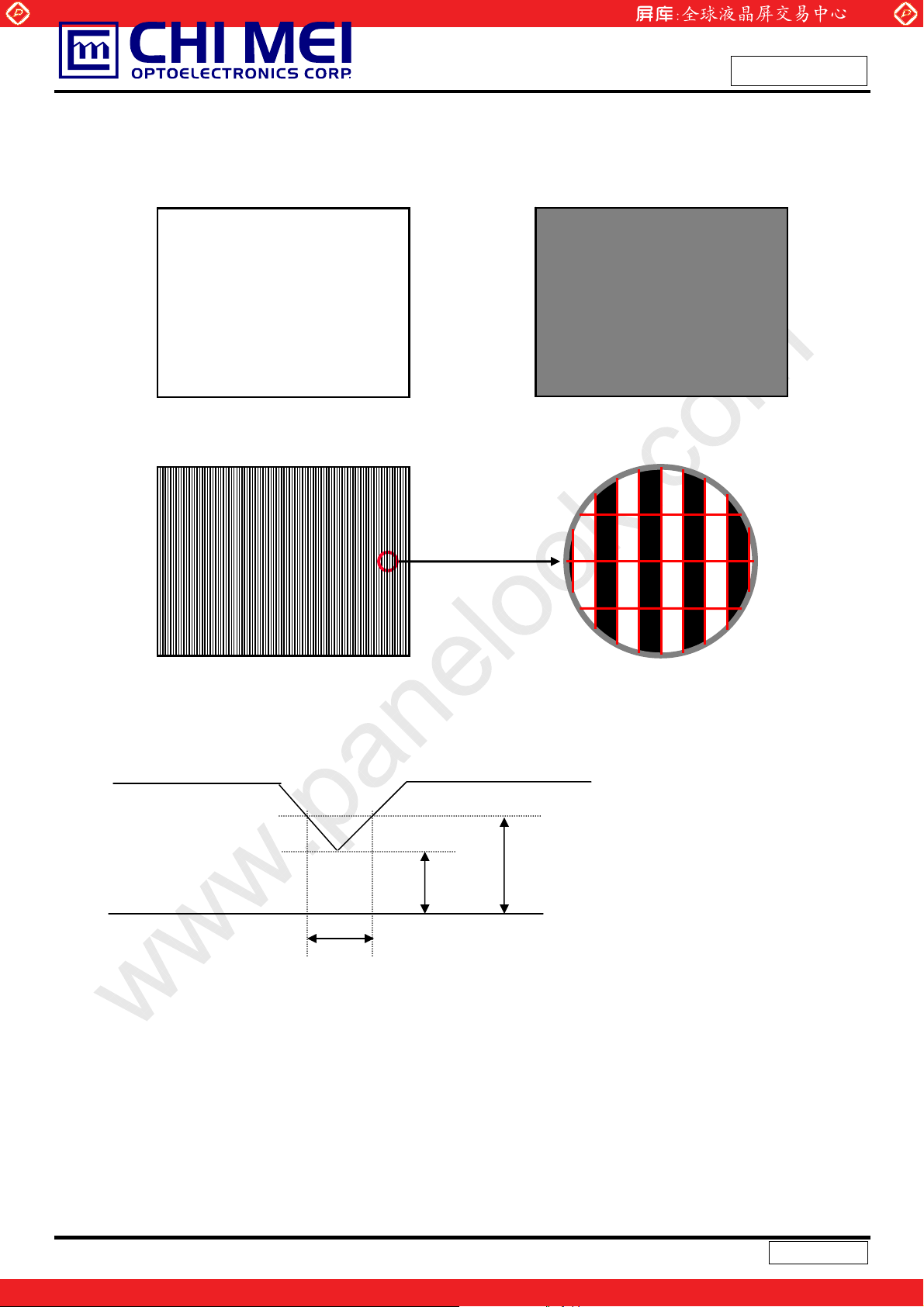
Note (3) The specified power supply current is under the conditions at Vcc = 5.0 V, Ta = 25 ± 2 ºC, fv = 60
Hz, whereas a power dissipation check pattern below is displayed.
www.panelook.com
Issued Date: Jul,14,2009
Model No.: M216H1-L07
Preliminary
a. White Pattern
Active Area
c. Vertical Stripe Pattern
b. Black Pattern
Active Area
R
G
R
B
G
R
B
G
R R
G
B
B
B
B
R
R
R
G
G
G
G
B
B
B
B
R
R
Note (4) The power consumption is specified at the pattern with the maximum current.
3.1.1 Vcc Power Dip Condition:
Active Area
Vcc
4.5V
Dip condition:
Td
msTdVVccV 20,5.40.4 ddd
4.0V
9 / 28
Version 1.0
One step solution for LCD / PDP / OLED panel application: Datasheet, inventory and accessory!
www.panelook.com
Page 10
Global LCD Panel Exchange Center
3.2 BACKLIGHT UNIT
Parameter Symbol
Lamp Input Voltage V
Lamp Current I
Lamp Turn On Voltage V
Operating Frequency F
Lamp Life Time L
Power Consumption P
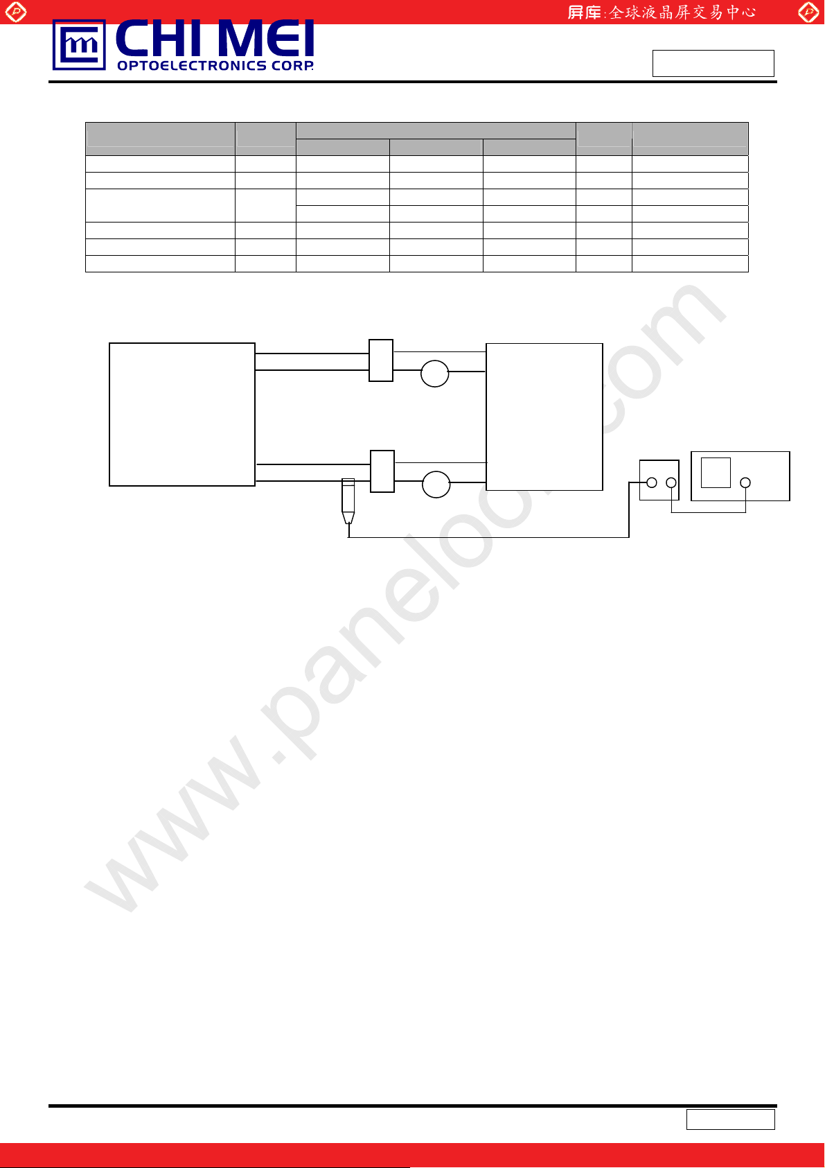
Note (1) Lamp current is measured by utilizing high-frequency current meters as shown below:
L
L
S
L
BL
L
www.panelook.com
Issued Date: Jul,14,2009
Model No.: M216H1-L07
Preliminary
Value
Min. Typ. Max.
774 860 946 V
3 7.5 8 mA
- - 1370(25°C) V
- - 1770(0°C) V
40 55 80 KHz (3)
40000 50000 - Hrs (5) IL = 7.5 mA
- 12.9 - W (4), IL = 7.5 mA
Unit Note
RMS
RMS
RMS
RMS
IL = 7.5 mA
(1)
(2)
(2)
LCD
Module
HV+ (Pink)
LV (White)
HV- (Pink)
LV (White)
Current
Probe
1
2
A
Inverter
Current
Amplify
1
2
A
Oscilloscope
Measure equipment:
Current Amplify: TektronixTCPA300
Current probe: Tektronix TCP312
Oscilloscope: TDS3054B
Ta = 25 ± 2 ºC
Note (2) The voltage that must be larger than Vs should be applied to the lamp for more than 1 second
after startu
p. Otherwise, the lamp may not be tur
ned on normally. It is the value output voltage of
NF circuit.
Note (3) The lamp frequency may produce interference with horizont
al synchronization frequency from the
display, which might cause line flow on the display. In order to avoid interference, the lamp
frequency should be detached from the horizontal synchronization frequency and its harmonics
as far as possible.
Note (4) P
Note (5) The lifetime of lamp can be defined as the time in whic
= IL ×VL X 2CCFLs
L
condition Ta = 25 ±2
o
C and IL = 7 mA until one of the following events occurs:
(a) When the brightness becomes Љ 50%
h it continues to operate under the
of its original value.
(b) When the effective ignition length becomes Љ 80% of its original value.
(The effective ignition length is a scope that luminance i
s over 80% of that at the
center point.)
Note (6) The waveform of the voltage output of inverter must be area-symmetri
c and the desig
n of the
inverter must have specifications for the modularized lamp. The performance of the Backlight,
such as lifetime or brightness, is greatly influenced by the characteristics of the DC-AC inverter
10 / 28
Version 1.0
One step solution for LCD / PDP / OLED panel application: Datasheet, inventory and accessory!
www.panelook.com
Page 11
Global LCD Panel Exchange Center
for the lamp. All the parameters of an inverter should be carefully designed to avoid producing too
much current leakage from high voltage output of the inverter. When designing or ordering the
inverter please make sure that a poor lighting caused by the mismatch of the Backlight and the
inverter (miss-lighting, flicker, etc.) never occurs. If the above situation is confirmed, the module
should be operated in the same manners when it is installed in your instrument.
www.panelook.com
Issued Date: Jul,14,2009
Model No.: M216H1-L07
Preliminary
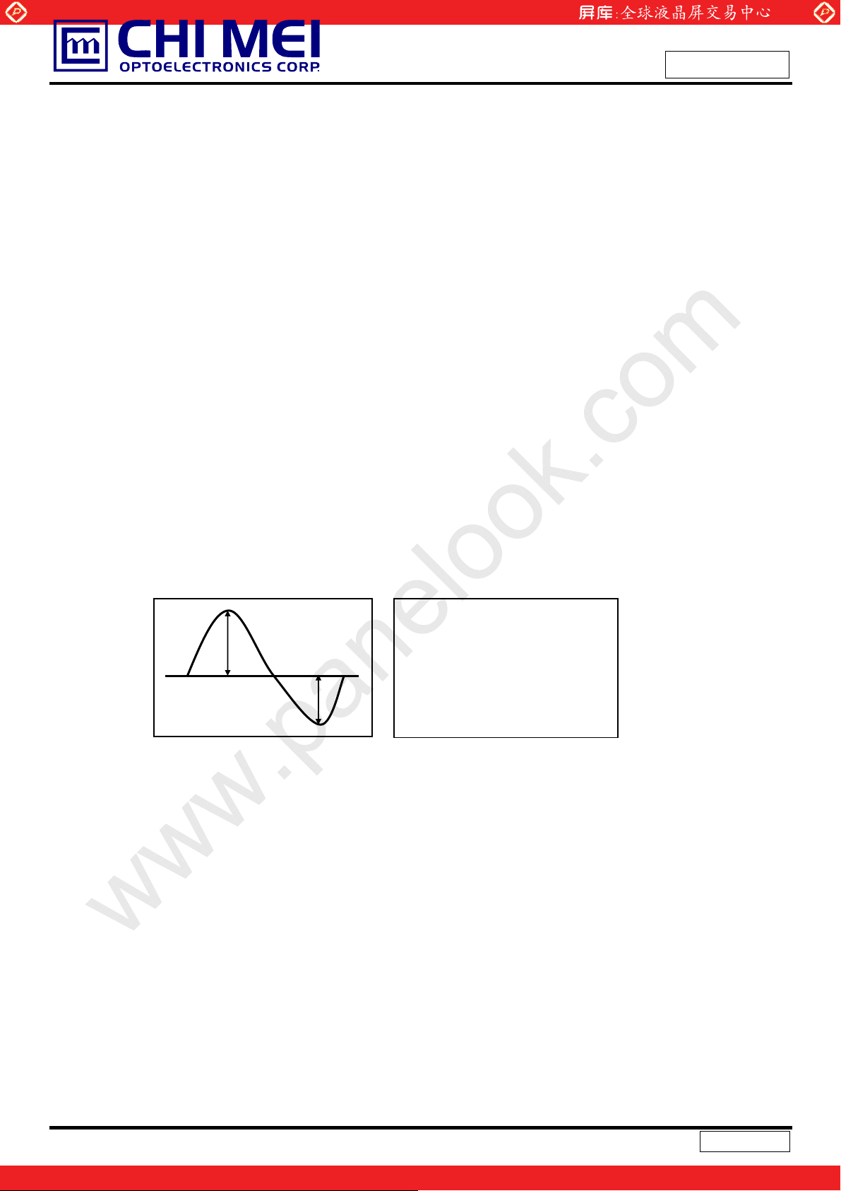
The output of the inverter must have symmetrical (negative and po
symmetrical current waveform.(Unsymmetrical ratio is less than 10%) Please do not use the inverter
which has unsymmetrical voltage and unsymmetrical current and spike wave. Lamp frequency may
produce interface with horizontal synchronous frequency and as a result this may cause beat on the
display. Therefore lamp frequency shall be as away possible from the horizontal synchronous
frequency and from its harmonics in order to prevent interference.
Requirements for a system inverter design, which is intended to h
better power efficiency and a more reliable lamp. It shall help increase the lamp lifetime and reduce its
leakage current.
a. The asymmetry rate of the inverter waveform should be 10% below;
b. The distortion rate of the waveform should be within Ѕ
c. The ide
al sine wave form shall be symmetric in positive and negative polarities.
* Asymmetry rate:
I p
| I
– I –p | / I
p
sitive) voltage waveform and
ave a better d
2 ± 10%;
* 100%
rms
isplay performance, a
I -p
* Distortion rate
I
(or I –p) / I
p
rms
11 / 28
Version 1.0
One step solution for LCD / PDP / OLED panel application: Datasheet, inventory and accessory!
www.panelook.com
Page 12
Global LCD Panel Exchange Center
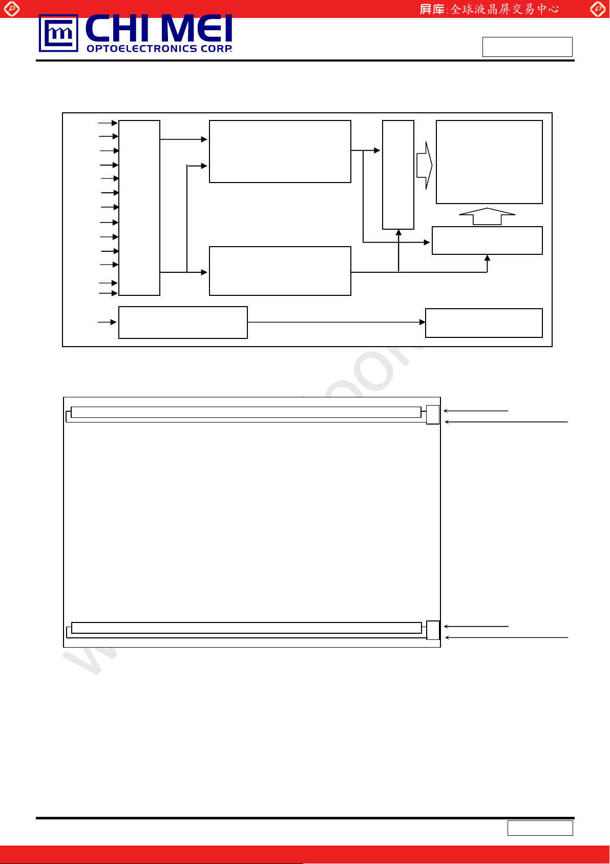
4. BLOCK DIAGRAM
4.1 TFT LCD MODULE
RXO0(+/-)
RXO1(+/-)
RXO2(+/-)
RXO3(+/-)
RXOC(+/-)
RXE0(+/-)
RXE1(+/-)
RXE2(+/-)
RXE3(+/-)
RXEC(+/-)
Vcc
GND
INPUT CONNECTOR
www.panelook.com
LVDS INPUT /
TIMING CONTROLLER
DC/DC CONVERTER &
REFERENCE VOLTAGE
Issued Date: Jul,14,2009
Model No.: M216H1-L07
Preliminary
SCAN DRIVER IC
TFT LCD PANEL
(1920x3x1080)
DATA DRIVER IC
VL
LAMP CONNECTOR
4.2 BACKLIGHT UNIT
(YEONHO 35001HS-02L)
BACKLIGHT UNIT
1 HV(Pink)
2 LV(White)
1 HV(Pink)
Note: On the same side, the same-polarity lamp voltage design for lamps is recommended
12 / 28
Version 1.0
One step solution for LCD / PDP / OLED panel application: Datasheet, inventory and accessory!
2 LV(White)
www.panelook.com
Page 13
Global LCD Panel Exchange Center
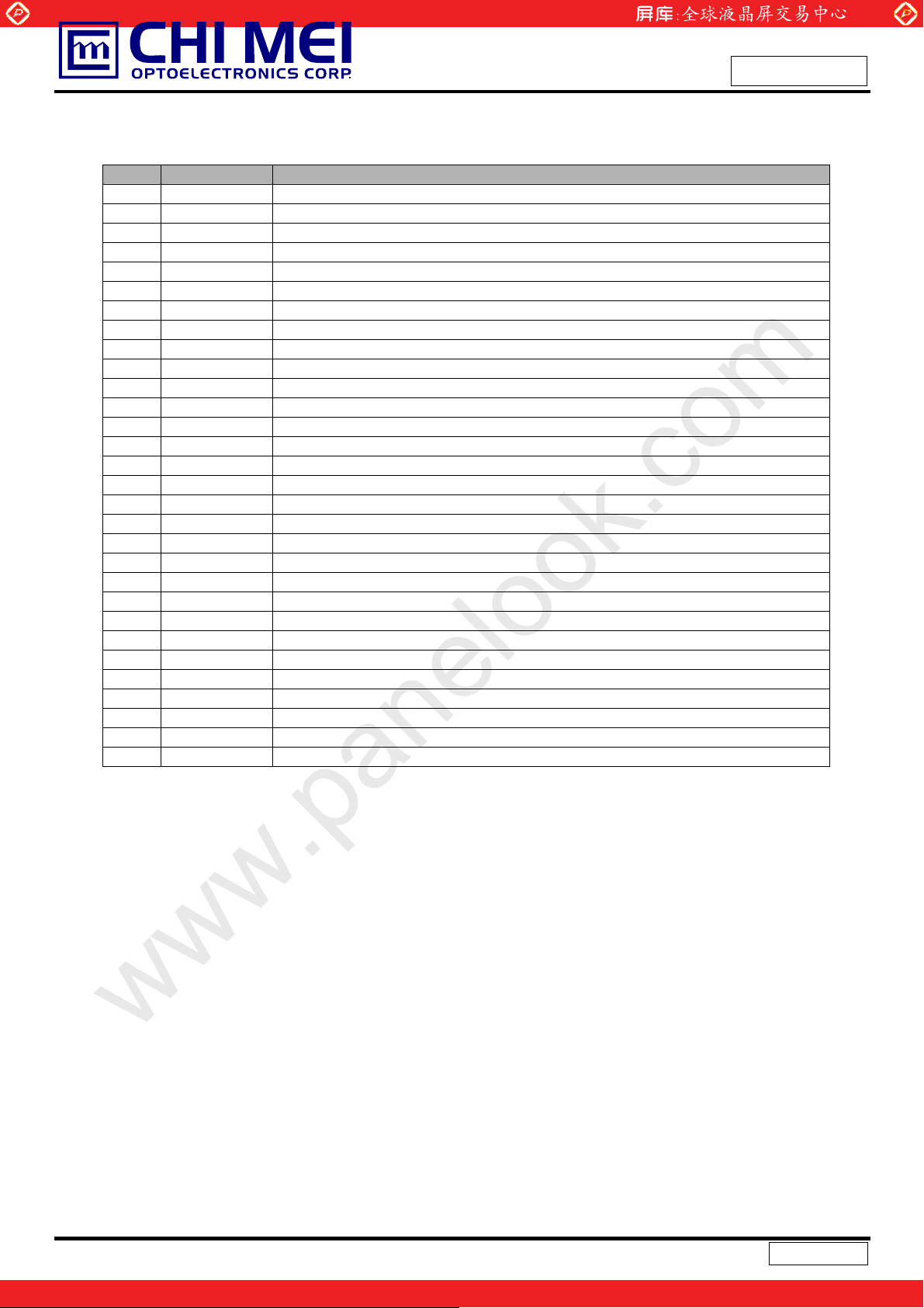
5. INPUT TERMINAL PIN ASSIGNMENT
5.1 TFT LCD MODULE
Pin Name Description
1 RXO0- Negative LVDS differential data input. Channel O0 (odd)
2 RXO0+ Positive LVDS differential data input. Channel O0 (odd)
3 RXO1- Negative LVDS differential data input. Channel O1 (odd)
4 RXO1+ Positive LVDS differential data input. Channel O1 (odd)
5 RXO2- Negative LVDS differential data input. Channel O2 (odd)
6 RXO2+ Positive LVDS differential data input. Channel O2 (odd)
7 GND Ground
8 RXOC- Negative LVDS differential clock input. (odd)
9 RXOC+ Positive LVDS differential clock input. (odd)
10 RXO3- Negative LVDS differential data input. Channel O3(odd)
11 RXO3+ Positive LVDS differential data input. Channel O3 (odd)
12 RXE0- Negative LVDS differential data input. Channel E0 (even)
13 RXE0+ Positive LVDS differential data input. Channel E0 (even)
14 GND Ground
15 RXE1- Negative LVDS differential data input. Channel E1 (even)
16 RXE1+ Positive LVDS differential data input. Channel E1 (even)
17 GND Ground
18 RXE2- Negative LVDS differential data input. Channel E2 (even)
19 RXE2+ Positive LVDS differential data input. Channel E2 (even)
20 RXEC- Negative LVDS differential clock input. (even)
21 RXEC+ Positive LVDS differential clock input. (even)
22 RXE3- Negative LVDS differential data input. Channel E3 (even)
23 RXE3+ Positive LVDS differential data input. Channel E3 (even)
24 GND Ground
25 NC Not connection, this pin should be open.
26 NC Not connection, this pin should be open.
27 NC Not connection, this pin should be open.
28 VCC +5.0V power supply
29 VCC +5.0V power supply
30 VCC +5.0V power supply
Note (1) Connector Part No.: 093G30-B0001A(STARCONN) or 10041195-002(FCI)
www.panelook.com
Issued Date: Jul,14,2009
Model No.: M216H1-L07
Preliminary
Note (2) Mating Wire Cable Connector Part No.: FI-X30H(JAE) or FI-X30HL(JAE)
Note (3) Mating FFC Cable Connector Part No.: 217007-013001 (P-TWO) or JF05X030-1 (JAE)
Note (4) The first pixel is odd.
Note (5) Input signal of even and odd clock should be the same timing.
13 / 28
Version 1.0
One step solution for LCD / PDP / OLED panel application: Datasheet, inventory and accessory!
www.panelook.com
Page 14
Global LCD Panel Exchange Center
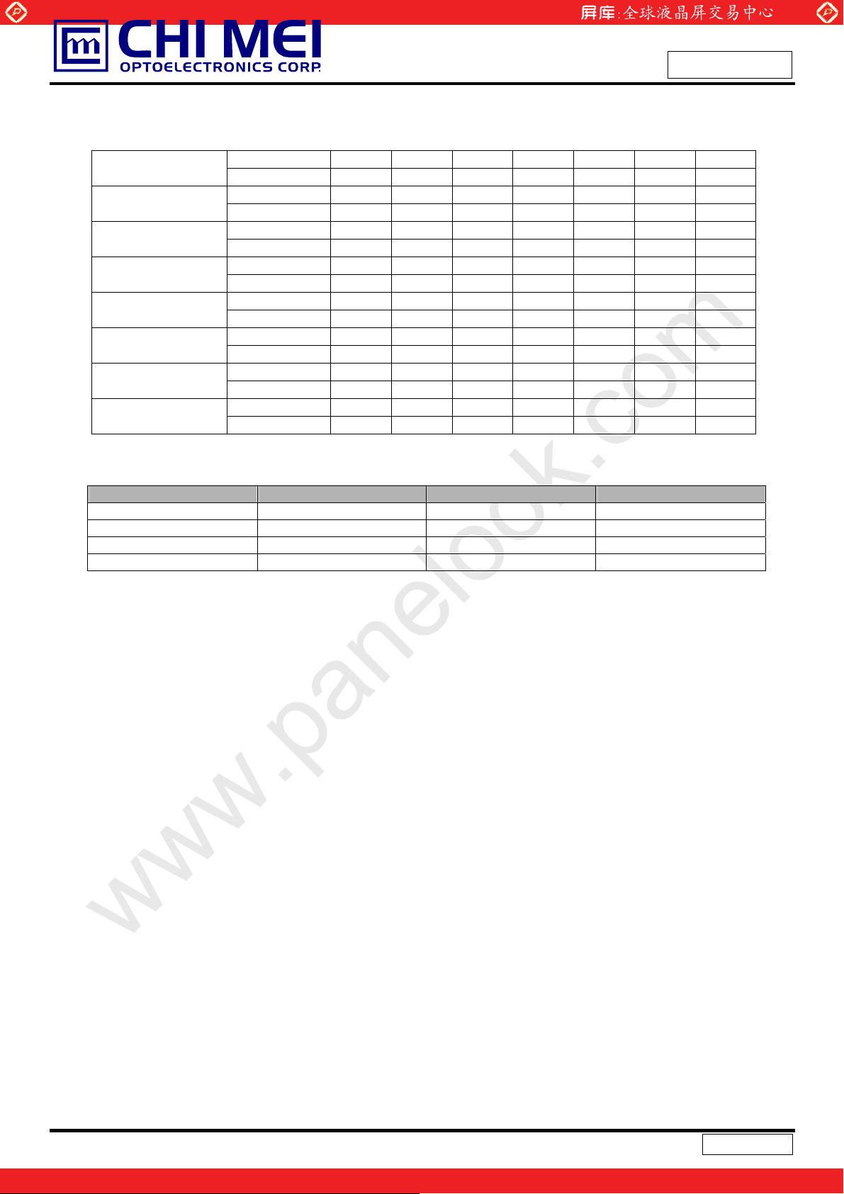
5.2 LVDS DATA MAPPING TABLE
LVDS Channel O0
LVDS Channel O1
LVDS Channel O2
LVDS Channel O3
LVDS Channel E0
LVDS Channel E1
LVDS Channel E2
LVDS Channel E3
LVDS output D7 D6 D4 D3 D2 D1 D0
Data order OG0 OR5 OR4 OR3 OR2 OR1 OR0
LVDS output D18 D15 D14 D13 D12 D9 D8
Data order OB1 OB0 OG5 OG4 OG3 OG2 OG1
LVDS output D26 D25 D24 D22 D21 D20 D19
Data order DE NA NA OB5 OB4 OB3 OB2
LVDS output D23 D17 D16 D11 D10 D5 D27
Data order NA OB7 OB6 OG7 OG6 OR7 OR6
LVDS output D7 D6 D4 D3 D2 D1 D0
Data order EG0 ER5 ER4 ER3 ER2 ER1 ER0
LVDS output D18 D15 D14 D13 D12 D9 D8
Data order EB1 EB0 EG5 EG4 EG3 EG2 EG1
LVDS output D26 D25 D24 D22 D21 D20 D19
Data order DE NA NA EB5 EB4 EB3 EB2
LVDS output D23 D17 D16 D11 D10 D5 D27
Data order NA EB7 EB6 EG7 EG6 ER7 ER6
www.panelook.com
Issued Date: Jul,14,2009
Model No.: M216H1-L07
Preliminary
5.3 BACKLIGHT UNIT
Pin Symbol Description Remark
1 HV High Voltage Pink
2 LV Low Voltage White
1 HV High Voltage Pink
2 LV Low Voltage White
Note (1) Connector Part No.: YEONHO 35001HS-02L or equivalent
Note (2) User’s connector Part No.: YEONHO 35001WR-02L or equivalent
14 / 28
Version 1.0
One step solution for LCD / PDP / OLED panel application: Datasheet, inventory and accessory!
www.panelook.com
Page 15
Global LCD Panel Exchange Center
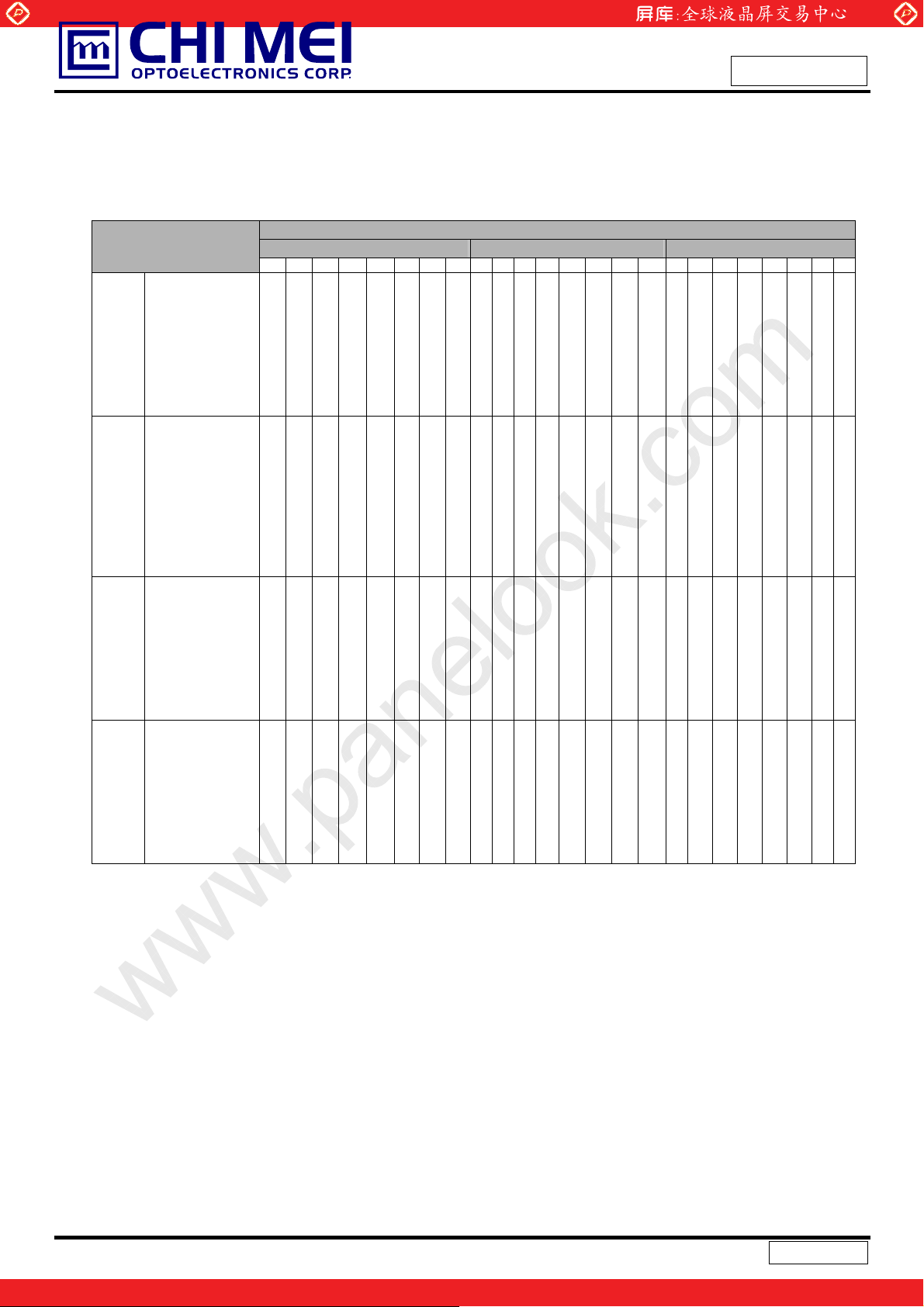
5.4 COLOR DATA INPUT ASSIGNMENT
The brightness of each primary color (red, green and blue) is based on the 8-bit gray scale data input for
the color. The higher the binary input, the brighter the color. The table below provides the assignment of
color versus data input.
Color
R7 R6 R5 R4 R3 R2 R1 R0 G7 G6 G5 G4 G3 G2 G1 G0 B7 B6 B5 B4 B3 B2 B1 B0
Basic
Colors
Gray
Scale
Of
Red
Black
Red
Green
Blue
Cyan
Magenta
Yellow
White
Red(0) / Dark
Red(1)
Red(2)
:
:
Red(253)
Red(254)
Red(255)
0
0
1
1
0
0
0
0
0
0
1
1
1
1
1
1
0
0
0
0
0
0
:
:
:
:
1
1
1
1
1
1
www.panelook.com
Issued Date: Jul,14,2009
Model No.: M216H1-L07
Data Signal
Red Green Blue
0
0
1
0
0
0
1
1
1
0
0
0
1
1
1
0
0
0
0
0
0
0
0
0
0
0
0
0
1
1
1
1
1
0
0
0
0
0
0
0
0
0
0
0
0
0
1
1
1
1
1
1
1
1
0
0
0
0
0
0
0
0
0
0
0
0
0
0
0
0
0
0
1
1
1
1
1
1
1
1
1
1
1
0
0
0
0
0
0
1
1
1
1
1
1
1
1
1
1
1
1
1
1
1
1
1
1
1
1
1
1
0
0
0
0
0
0
0
0
0
0
0
0
0
0
0
1
0
0
0
0
0
0
0
0
0
1
0
0
0
0
0
0
0
:
:
:
:
:
:
:
:
:
:
:
:
:
:
:
:
:
:
:
:
:
:
:
:
1
1
1
0
1
0
0
0
0
0
0
1
1
1
1
0
0
0
0
0
0
0
1
1
1
1
1
0
0
0
0
0
0
1
1
0
0
1
1
1
1
0
0
0
0
0
0
:
:
0
0
0
0
0
0
0
0
0
0
0
1
1
1
1
1
1
0
0
1
1
0
0
0
0
0
0
:
:
:
:
:
:
0
0
0
0
0
0
Preliminary
0
0
0
0
0
0
0
0
0
0
0
0
0
0
0
0
0
0
1
1
1
1
1
1
1
1
1
1
1
1
1
1
1
1
1
1
0
0
0
0
0
0
1
1
1
1
1
1
0
0
0
0
0
0
0
0
0
0
0
0
0
0
0
0
0
0
:
:
:
:
:
:
:
:
:
:
0
0
0
0
0
0
0
0
0
0
0
0
0
0
0
0
0
0
:
:
Green(0) / Dark
Gray
Scale
Of
Green
Gray
Scale
Of
Blue
Note (1) 0: Low Level Voltage, 1: High Level Voltage
Green(1)
Green(2)
:
:
Green(253)
Green(254)
Green(255)
Blue(0) / Dark
Blue(1)
Blue(2)
:
:
Blue(253)
Blue(254)
Blue(255)
0
0
0
0
0
0
0
0
0
0
0
0
0
0
0
0
0
0
0
0
0
:
:
:
:
:
:
:
:
:
:
:
:
:
:
0
0
0
0
0
0
0
0
0
0
0
0
0
0
0
0
0
0
0
0
0
0
0
0
0
0
0
0
0
0
0
0
0
0
0
0
0
0
0
0
0
0
:
:
:
:
:
:
:
:
:
:
:
:
:
:
0
0
0
0
0
0
0
0
0
0
0
0
0
0
0
0
0
0
0
0
0
0
0
0
0
0
0
0
0
0
0
0
0
0
0
0
0
1
0
0
0
0
0
0
0
0
0
0
0
1
1
1
0
0
:
:
:
:
0
0
0
0
0
0
:
:
:
:
1
1
1
0
0
0
0
0
0
0
0
0
0
0
0
0
0
0
0
0
0
1
:
:
:
:
:
:
:
:
:
:
:
:
:
:
0
1
1
1
1
1
1
0
1
1
1
1
1
1
0
1
1
1
1
1
1
0
0
0
0
0
0
0
0
0
0
0
0
0
0
0
0
0
0
0
0
0
:
:
:
:
:
:
:
:
:
:
:
:
:
:
0
0
0
0
0
0
0
0
0
0
0
0
0
0
0
0
0
0
0
0
0
:
:
:
:
1
0
1
0
0
0
0
0
0
0
0
0
0
0
0
:
:
1
1
1
0
1
1
0
0
0
:
:
0
0
0
0
:
:
:
:
:
:
0
0
0
0
0
0
0
0
0
0
0
0
:
:
:
:
:
:
1
1
1
1
1
1
0
0
0
0
0
0
0
:
:
:
:
:
:
0
0
0
0
0
0
0
0
0
0
0
0
0
0
1
0
1
0
:
:
:
:
:
:
1
0
1
1
1
0
1
1
1
15 / 28
Version 1.0
One step solution for LCD / PDP / OLED panel application: Datasheet, inventory and accessory!
www.panelook.com
Page 16
Global LCD Panel Exchange Center
6. INTERFACE TIMING
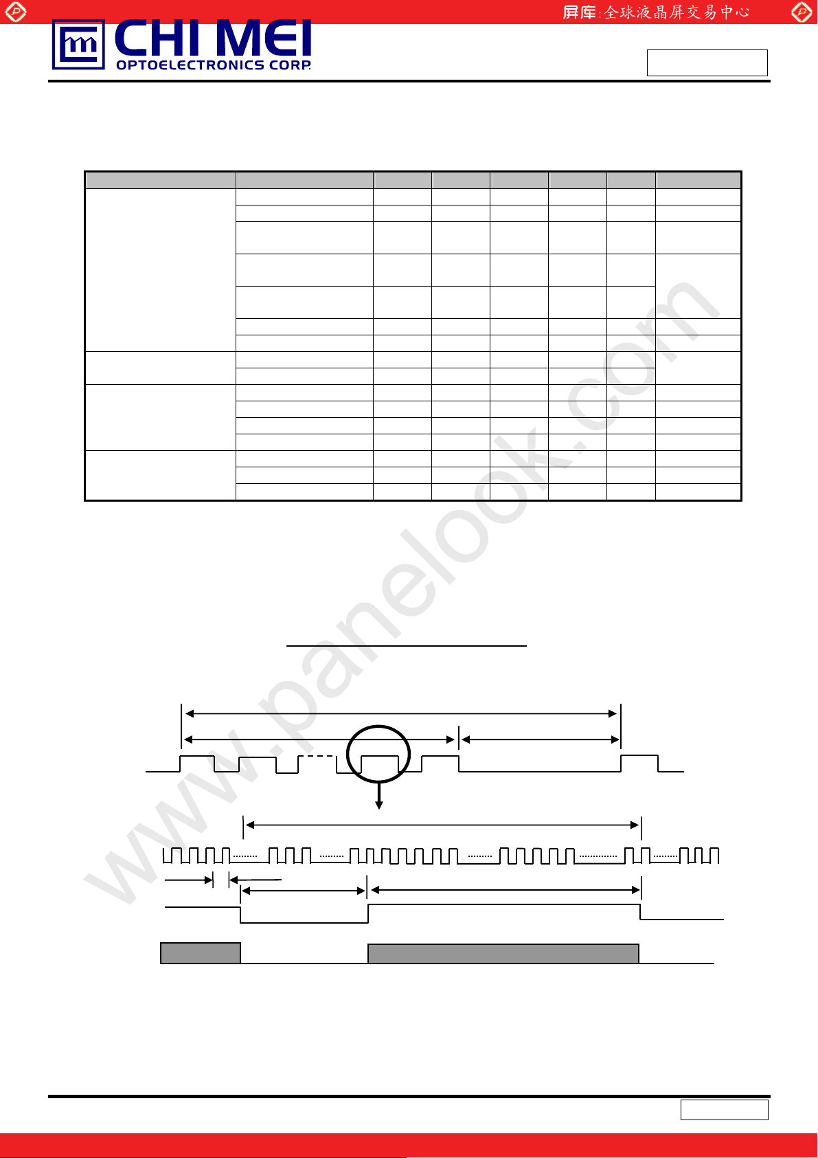
6.1 INPUT SIGNAL TIMING SPECIFICATIONS
The input signal timing specifications are shown as the following table and timing diagram.
Signal Item Symbol Min. Typ. Max. Unit Note
Frequency Fc 58.54 74.25 98 MHz Period Tc - 13.47 - ns Input cycle to
cycle jitter
LVDS Clock
LVDS Data
Vertical Active Display
Te rm
Horizontal Active
Display Term
NoteΚ(1) Because this module is operated by DE only mode, Hsync and Vsync input signals should be
Spread spectrum
modulation range
Spread spectrum
modulation frequency
High Time Tch - 4/7 - Tc Low Time Tcl - 3/7 - Tc Setup Time Tlvs 600 - - ps
Hold Time Tlvh 600 - - ps
Frame Rate Fr 50 60 75 Hz Tv=Tvd+Tvb
Total Tv 1115 1125 1136 Th Display Tvd 1080 1080 1080 Th Blank Tvb 35 45 56 Th Total Th 1050 1100 1150 Tc Th=Thd+Thb
Display Thd 960 960 960 Tc Blank Thb 90 140 190 Tc -
www.panelook.com
T
clkin_mod
F
F
SSM
rcl
- - 200 ps (2)
F
-2% - F
clkin
- - 200 KHz
Issued Date: Jul,14,2009
Model No.: M216H1-L07
+2% MHz
clkin
Preliminary
(3)
(4)
set to low logic level or ground. Otherwise, this module would operate abnormally.
INPUT SIGNAL TIMING DIAGRAM
DE
T
h
DCLK
T
DE
C
Thb
hd
T
DATA
16 / 28
Version 1.0
One step solution for LCD / PDP / OLED panel application: Datasheet, inventory and accessory!
www.panelook.com
Page 17
Global LCD Panel Exchange Center
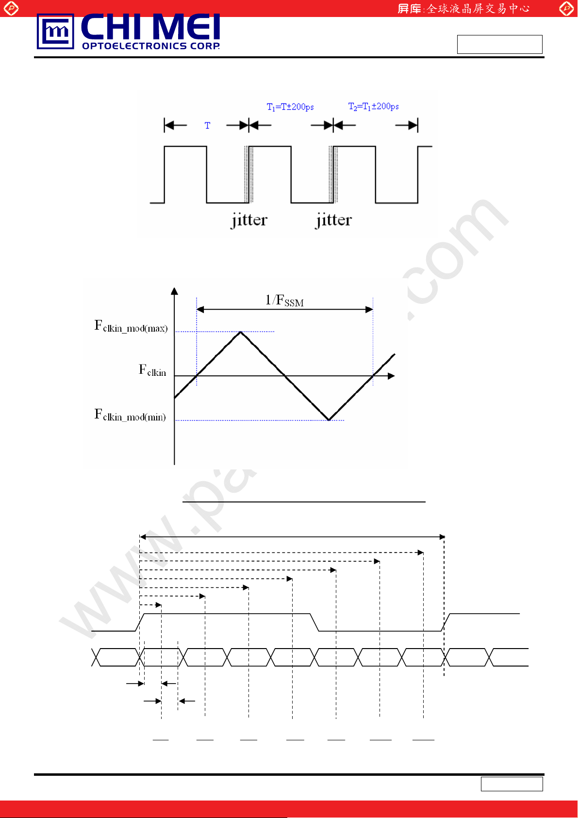
Note (2) The input clock cycle-to-cycle jitter is defined as below figures. Trcl = I T1 – TI
www.panelook.com
Issued Date: Jul,14,2009
Model No.: M216H1-L07
Preliminary
Note (3) The SSCG (Spread spectrum clock gen
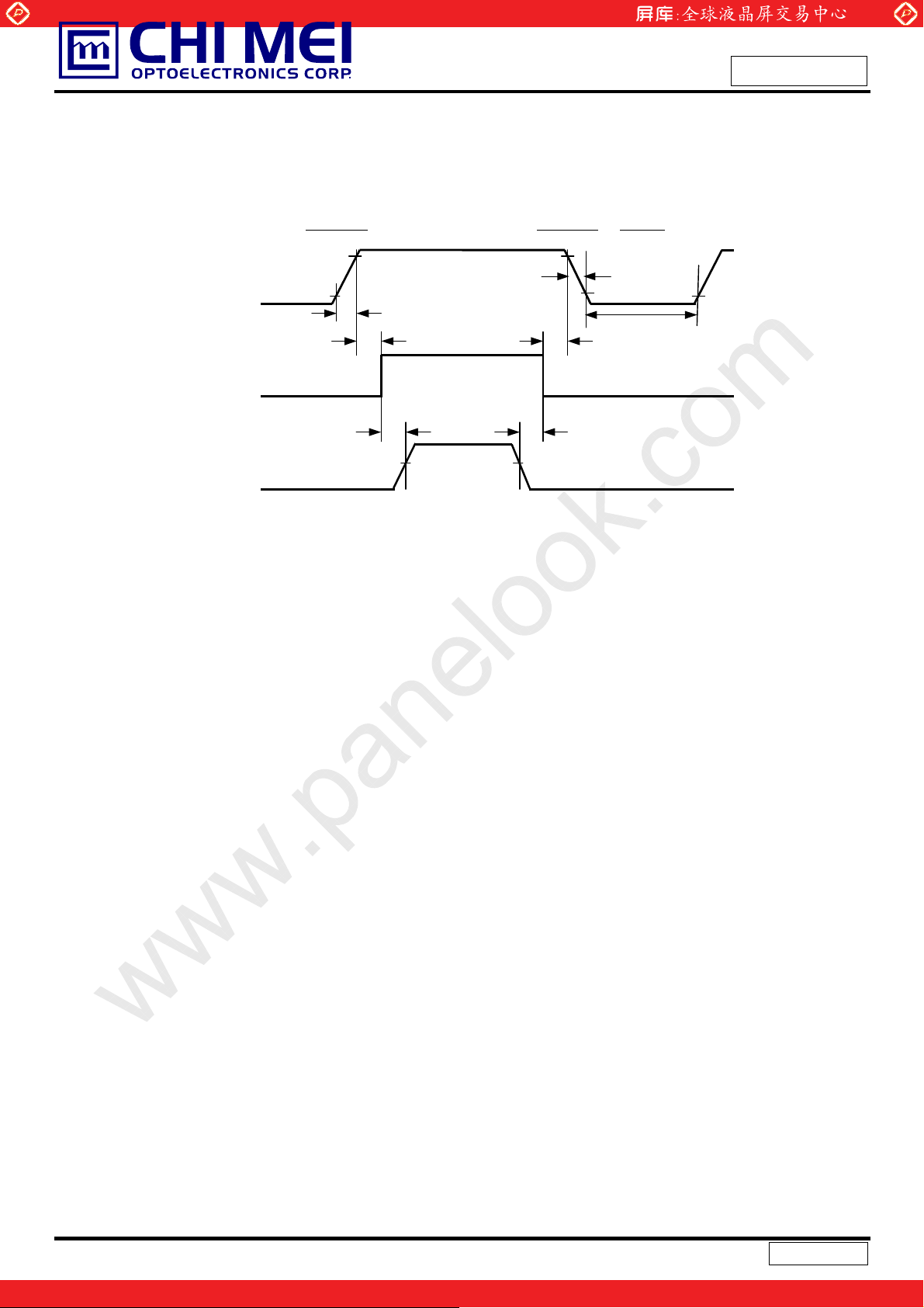
Note (4) The LVDS timing diagram and setup/hold time is defined and showing as the following figures.
LVDS RECEIVER INTERFACE TIMING DIAGRAM
erator) is defined a
Tc
s below figures.
RXCLK+/-
RXn+/-
Version 1.0
One step solution for LCD / PDP / OLED panel application: Datasheet, inventory and accessory!
Tlvs
Tlvh
1
14
7
T
c
3
14
T
c
T
5
c
14
T
c
14
17 / 28
9
14
T
c
11
14
T
c
13
T
c
14
www.panelook.com
Page 18
Global LCD Panel Exchange Center
www.panelook.com
Issued Date: Jul,14,2009
Model No.: M216H1-L07
Preliminary
6.2 POWER ON/OFF SEQUENCE
To prevent a latch-up or DC operation of LCD module, the power on/off sequence should be as the
diagram below.
Restart
Power On
Power Off
Power Supply
for LCD, Vcc
-
Interface Signal
(LVDS Signal of
Transmitter), V
-
Power for Lamp
0V
0V
I
Timing Specifications:
0.5< t1 Љ 10 msec
0 < t2 Љ
50 msec
0 < t3 Љ 50 msec
t4 Њ 500 msec
t5 Њ 450 msec
10%
90%
t1
t2
90%
Valid Data
t6 t5
50%50%
ONOFF OFF
t3
t7
10%
10%
t4
t6 Њ 90 msec
5 Љt7 Љ 100
msec
Note.
(1) The supply voltage of the external system for the module input should be
(2) Apply the lamp voltage within the LCD operation range
. When the backlight turns on before the LCD
the same as the definition of Vcc.
operation of the LCD turns off before the backlight turns off, the display may momentarily become abnormal
screen.
(3) In case of VCC = off level, please keep the level of input signals on
the low or keep a high impedance.
(4) T4 should be measured after the module has been fully discharged between power off and on period.
(5) Interface signal shall not be kept at high impedance when the power is on.
(6) CMO won’t take any responsibility for the products which are damaged by the customers
not following
Power Sequence.
(7) There might be slight electronic noise when LCD is turned off (even ba
ht unit is also off). To avoid this
cklig
symptom, we suggest "Vcc falling timing" to follow "t7 spec"
the
18 / 28
Version 1.0
One step solution for LCD / PDP / OLED panel application: Datasheet, inventory and accessory!
www.panelook.com
Page 19
Global LCD Panel Exchange Center
7. OPTICAL CHARACTERISTICS
7.1 TEST CONDITIONS
Item Symbol Value Unit
Ambient Temperature Ta
Ambient Humidity Ha
Supply Voltage V
Input Signal According to typical value in "3. ELECTRICAL CHARACTERISTICS"
Inverter Current I
Inverter Driving Frequency F
Inverter Logah MIT70070.50
7.2 OPTICAL SPECIFICATIONS
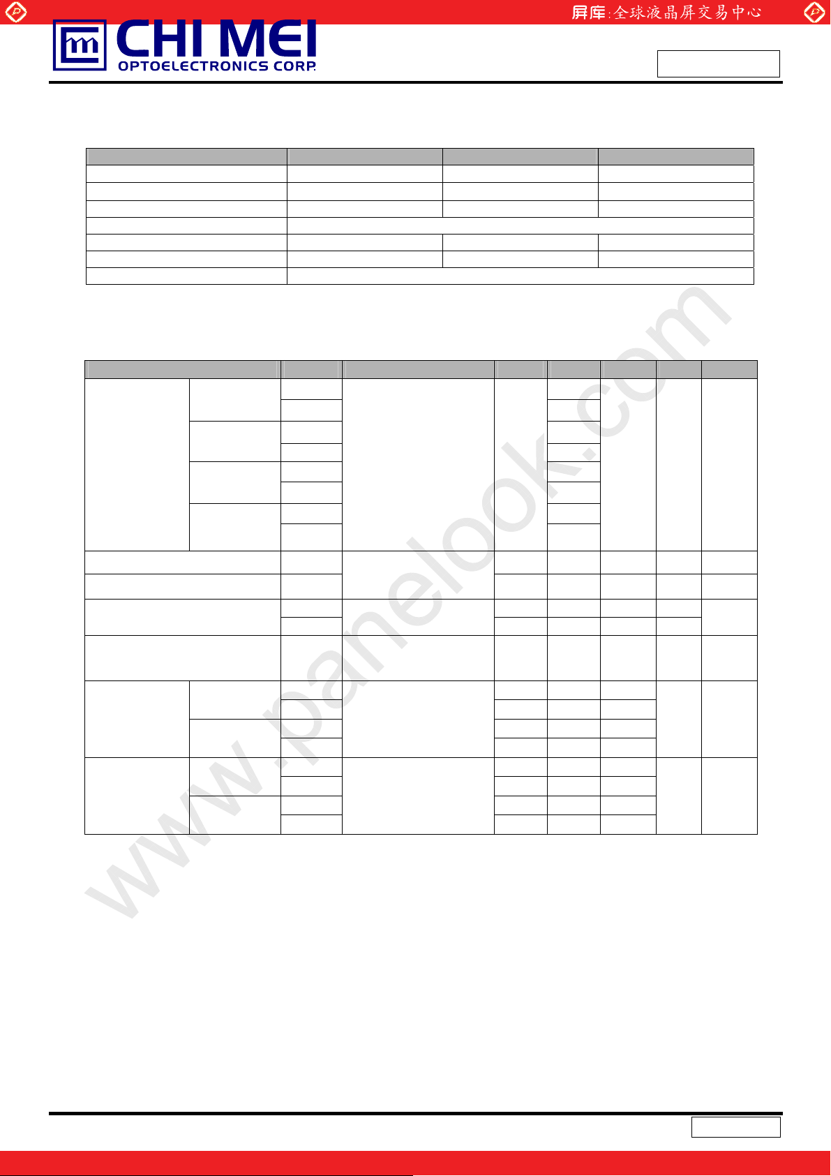
The relative measurement methods of optical characteristics are shown in 7.2. The following items should
be measured under the test conditions described in 7.1 and stable environment shown in Note (6).
Item Symbol Condition Min. Typ. Max. Unit Note
Red
Green
Color
Chromaticity
Blue
White
Rx
Ry
Gx
Gy
Bx
By
Wx
Wy
www.panelook.com
CC
L
L
T
=0q, TY =0q
x
CS-1000T
R=G=B=2
Grayscale
55
Issued Date: Jul,14,2009
Model No.: M216H1-L07
Preliminary
o
25r2
50r10
5.0 V
7.5±0.5 mA
55±5 KHz
0.651
0.334
0.286
Typ –
0.03
0.600
0.152
Typ +
0.03
0.075
0.313
0.329
C
%RH
- (1), (5)
Center Luminance of White L
C
Contrast Ratio CR
T
Response Time
White Variation
Horizontal
Viewing Angle
Vertical
Horizontal
Viewing Angle
Vertical
R
T
F
GW
Tx+
T
x
TY+
T
Y
Tx+
T
x
TY+
T
Y
-
-
-
-
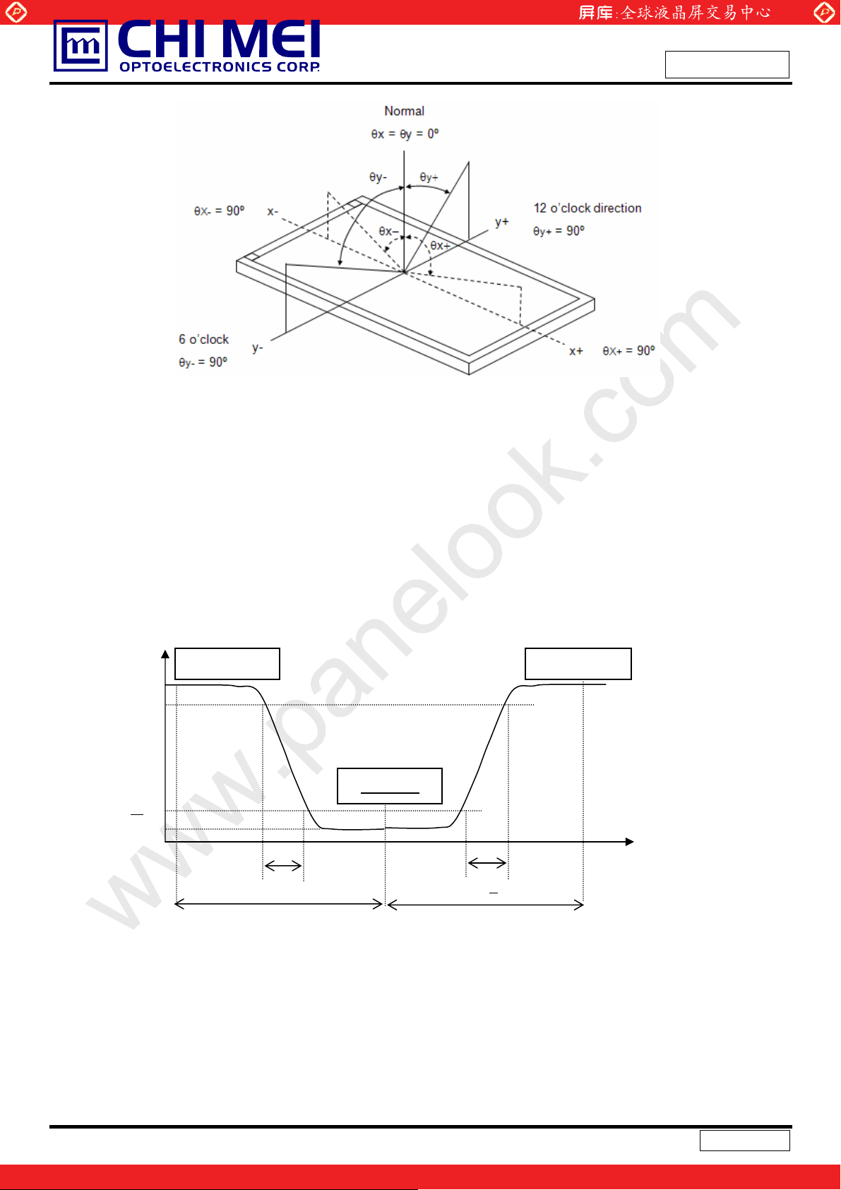
Note (1) Definition of Viewing Angle (Tx, Ty):
Tx=0q, TY =0q
T
=0q, TY =0q
x
USB2000
CR>10
USB2000
CR>5
USB2000
200 250 --- cd/m2(4), (5)
800 1200 --- - (2), (6)
--- 1.0 2.2 ms
--- 2.0 5.5 ms
(3)
--- ---- 1.33 - (5), (6)
75
75
70
70
80
80
75
75
85 --85
80
80
---
---
--89 --89
85
85
---
---
---
Deg. (1), (5)
Deg. (1), (5)
19 / 28
Version 1.0
One step solution for LCD / PDP / OLED panel application: Datasheet, inventory and accessory!
www.panelook.com
Page 20
Global LCD Panel Exchange Center
Note (2) Definition of Contrast Ratio (CR):
www.panelook.com
Issued Date: Jul,14,2009
Model No.: M216H1-L07
Preliminary
The contrast ratio can be calculated by the followi
Contrast Ratio (CR) = L255 / L0
L255: Luminance of gray level 255
L 0: Luminance of gray level 0
CR = CR (5)
CR (X) is corresponding to the Contrast Ratio of the point X at Figure in Note (6).
Note (3) Definition of Response Time (T
100%
90%
Optical
Response
10
0%
T
R
66.67ms
, TF):
R
Gray Leve
pression.
ng ex
Gray Level 255 Gray Level 255
Time
T
66.67ms
20 / 28
Version 1.0
One step solution for LCD / PDP / OLED panel application: Datasheet, inventory and accessory!
www.panelook.com
Page 21
Global LCD Panel Exchange Center
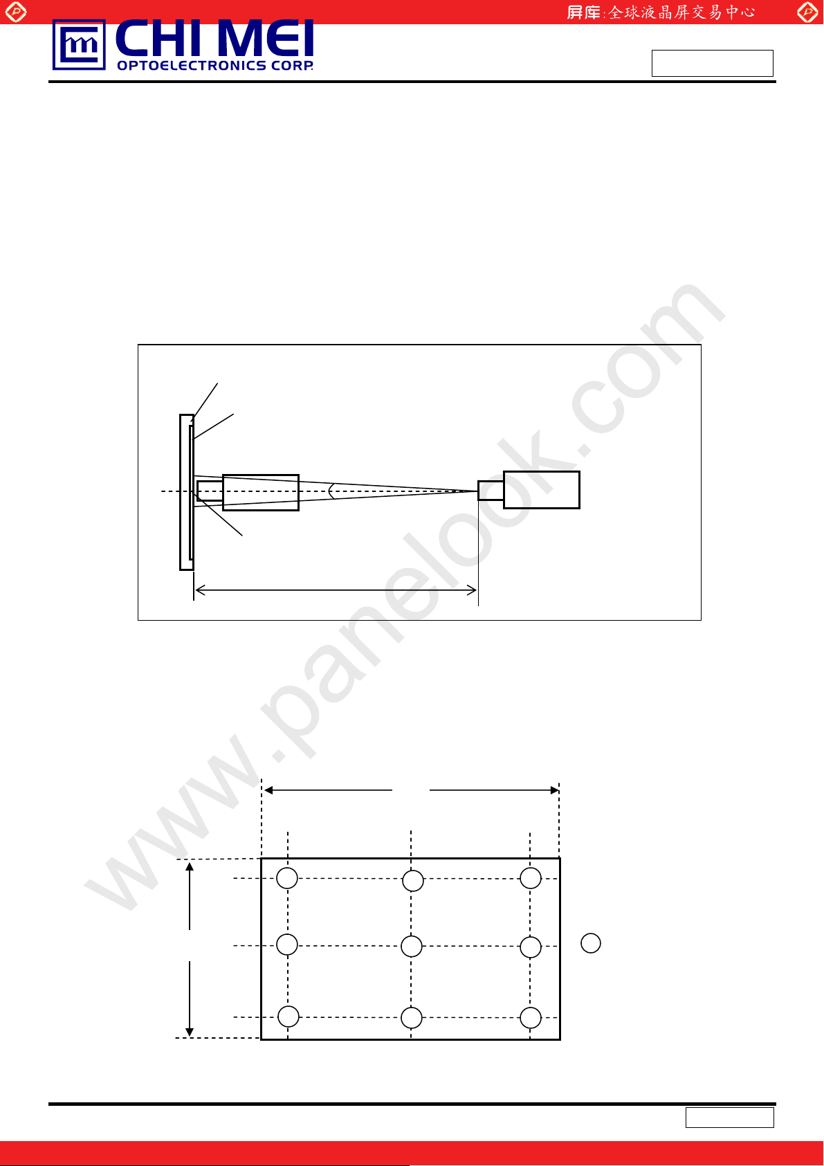
Note (4) Definition of Luminance of White (LC):
Measure the luminance of gray level 255 at center point
L
= L (5)
C
L (x) is corresponding to the luminance of the point X at Figure in Note (6).
www.panelook.com
Issued Date: Jul,14,2009
Model No.: M216H1-L07
Preliminary
Note (5) Mea
surement Setup:
The LCD module should be stabilized at given temperature for 30 minutes to avoid abrupt
temperature cha
should be executed after lighting Backlight for 30 minutes in a windless room.
nge durin
g measuring. In order to stabilize the luminance, the measurement
Gray 0
LCD Module
LCD Panel
USB2000
CS-1000T
Field of View = 2º
Center of the Screen
500 mm
Light Shield Room
(Ambient Luminance < 2 lux)
Note (6) Definition of White Variation (GW):
Measure the luminance of gray level 255 at 9 points
GW = Max
Vertical Line
imum [L (1) ~ L (9)] / Minimum [L (1) ~ L (9)]
Horizontal Line
D
D/10 D/2
1 3
4
7
2
5
8
W
W/10
W/2
W/10
D/10
6
9
X
: Test Point
X=1 to 9
Active Area
21 / 28
Version 1.0
One step solution for LCD / PDP / OLED panel application: Datasheet, inventory and accessory!
www.panelook.com
Page 22
Global LCD Panel Exchange Center
8. PACKAGING
8.1 PACKING SPECIFICATIONS
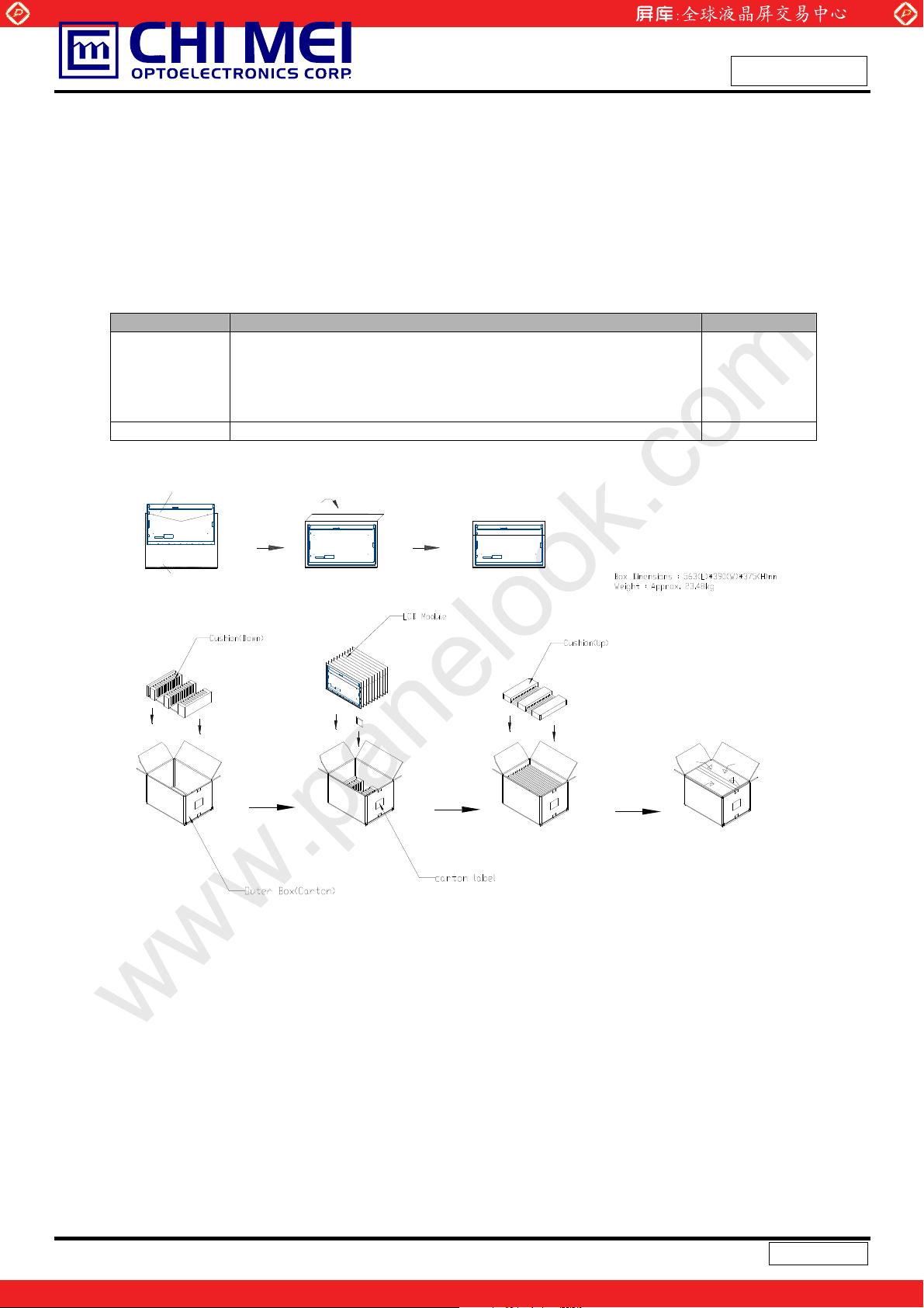
(1) 11 LCD modules / 1 Box
(2) Box dimensions: 563(L) X 390 (W) X 375 (H) mm
(3) Weight: 23.48 Kg (11 modules per box)
8.2 PACKING METHOD
(1) Carton Packing should have no failure in the following reliability test items.
Test Item Test Conditions Note
ISTA STANDARD
Random, Frequency Range: 1 – 200 Hz
Vibration
Dropping Test 1 Conner, 3 Edge, 6 Face, for ISTA Standard Non Operation
Top & Bottom: 30 minutes (+Z), 10 min (-Z),
Right & Left: 10 minutes (X)
Back & Forth 10 minutes (Y)
www.panelook.com
Issued Date: Jul,14,2009
Model No.: M216H1-L07
Preliminary
Non Operation
LCD Module
Anti-static Bag
Figure. 8-1 Packing method
22 / 28
Version 1.0
One step solution for LCD / PDP / OLED panel application: Datasheet, inventory and accessory!
www.panelook.com
Page 23
Global LCD Panel Exchange Center
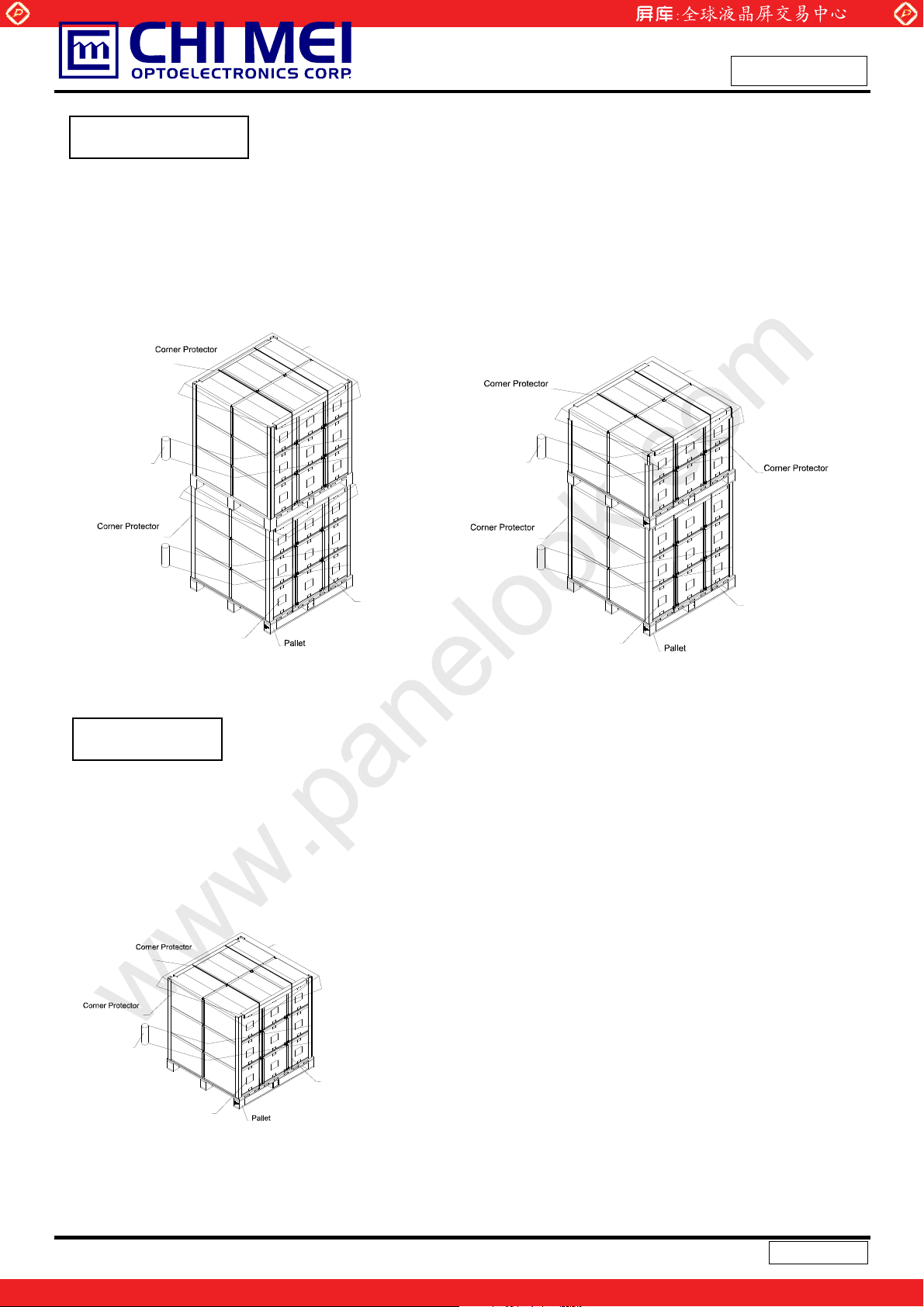
For Ocean shipping
www.panelook.com
Issued Date: Jul,14,2009
Model No.: M216H1-L07
Preliminary
Sea / Land Transportation
(40ft HQ Container)
(L1000mm,t=3mm)
Film
(L1130mm,t=5mm)
Carton Label
PE Sheet
(L1150*W1190*H143mm)
PP Belt
Sea / Land Transportation
(40ft Container)
PE Sheet
(L1000mm,t=3mm)
Film
(L625mm,t=5mm)
(L1130mm,t=5mm)
PP Belt
Carton Label
(L1150*W1190*H143mm)
Figure. 8-2 Packing method
For Air transport
Air Transportation
(L1000mm,t=3mm)
(L1130mm,t=5mm)
Film
Carton Label
PE Sheet
PP Belt
(L1150*W1190*H143mm)
Figure. 8-3 Packing method
23 / 28
Version 1.0
One step solution for LCD / PDP / OLED panel application: Datasheet, inventory and accessory!
www.panelook.com
Page 24
Global LCD Panel Exchange Center
9. DEFINITION OF LABELS
9.1 CMO MODULE LABEL
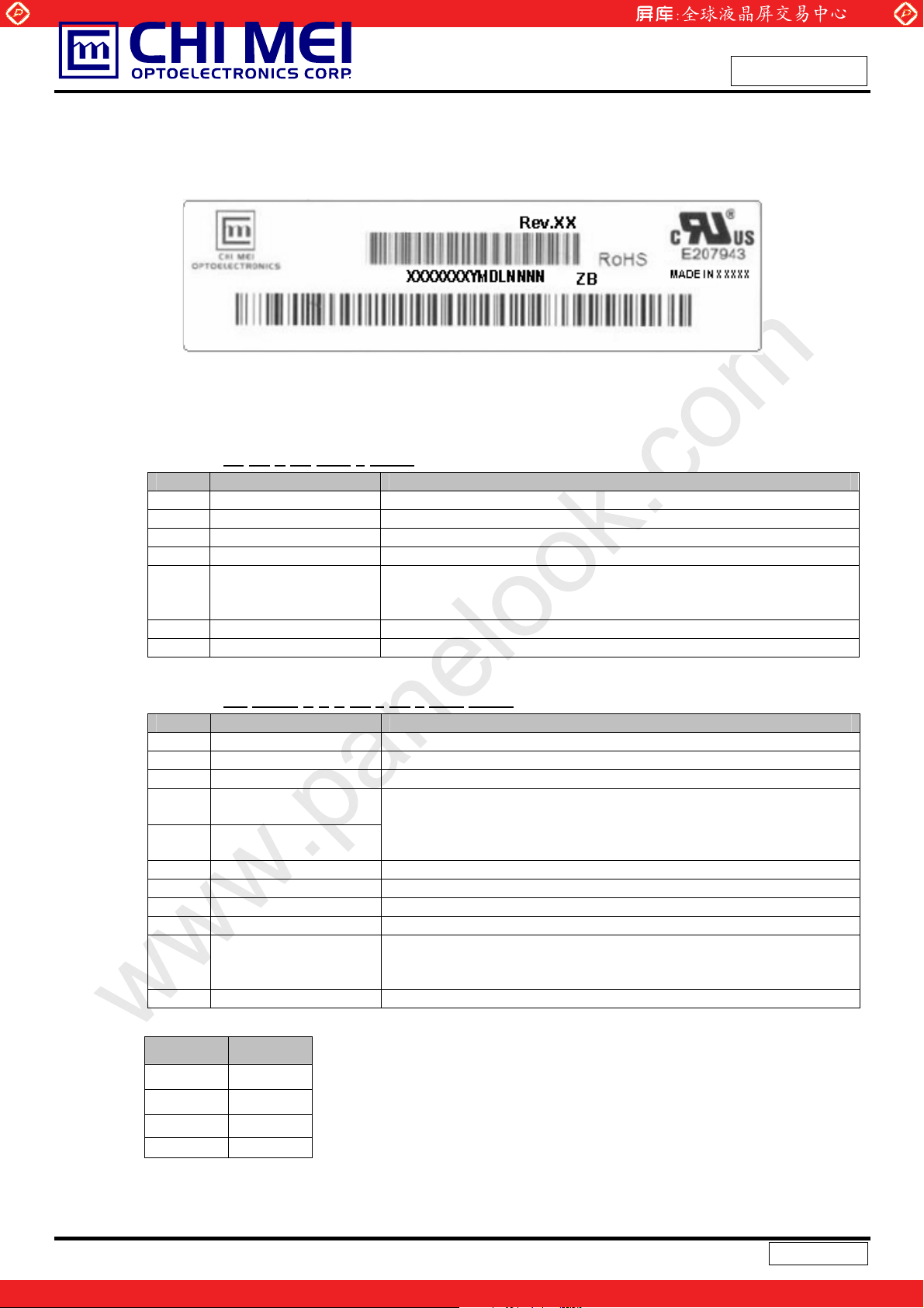
The barcode nameplate is pasted on each module as illustration, and its definitions are as following explanation.
www.panelook.com
Issued Date: Jul,14,2009
Model No.: M216H1-L07
Preliminary
M216H1-L07
CM21H17XXXXXLXXLYMDNNNN
(a) Model Name: M216H1-L07
(b) Revision: Rev. XX, for example: A0, A1… B1, B2… or C1, C2…etc.
(c) CMO barcode definition:
Serial ID: XX
Code Meaning Description
XX CMO internal use XX Revision Cover all the change
X CMO internal use -
XX CMO internal use -
YMD Year, month, day
L Product line # Line 1=1, Line 2=2, Line 3=3, …
NNNN Serial number Manufacturing sequence of product
(d) Customer’s barcode definition:
-XX-X-XX-YMD-L-NNNN
Year: 2001=1, 2002=2, 2003=3, 2004=4…
Month: 1~12=1, 2, 3, ~, 9, A, B, C
Day: 1~31=1, 2, 3, ~, 9, A, B, C, ~, W, X,
(Fab ID)
Y, exclude I, O, and U.
Serial ID: CM
Code Meaning Description
CM Supplier code CMO=CM
21H17 Model number M216H1-L07=21H17
X Revision code Non ZBD: 1,2,~,8,9 / ZBD: A~Z
X Source driver IC code
X Gate driver IC code
XX Cell location Tainan, Taiwan=TN
L Cell line # 1,2,~,9,A,B,~,Y,Z
XX Module location Tainan, Taiwan=TN ; Ningbo China=NP
L Module line # 1,2,~,9,A,B,~,Y,Z
YMD Year, month, day
NNNN Serial number Manufacturing sequence of product
(e) FAB ID(UL Factory ID):
Region Factory ID
TWCMO GEMN
NBCMO LEOO
NBCME CANO
NHCMO CAPG
-21H17-X-X-X-XX-L-XX-L-YMD-NNNN
Century=1, CLL=2, Demos=3, Epson=4, Fujitsu=5,
Hitachi=7, Hynix=8, LDI=9, Matsushita=A, NEC=B, Novatec=C,
OKI=D, Philips=E, Renasas=F, Samsung=G, Sanyo=H, Sharp=I,
TI=J, Topro=K, Toshiba=L, Windbond=M
Year: 2001=1, 2002=2, 2003=3, 2004=4…
Month: 1~12=1, 2, 3, ~, 9, A, B, C
Day: 1~31=1, 2, 3, ~, 9, A, B, C, ~, T, U, V
Himax=6,
24 / 28
Version 1.0
One step solution for LCD / PDP / OLED panel application: Datasheet, inventory and accessory!
www.panelook.com
Page 25
Global LCD Panel Exchange Center
10. Reliability Test
Environment test conditions are listed as following table.
Items Required Condition Note
Temperature Humidity Bias (THB)
High Temperature Operation (HTO)
Low Temperature Operation (LTO)
High Temperature Storage (HTS)
Low Temperature Storage (LTS)
Vibration Test
(Non-operation)
Shock Test
(Non-operation)
Thermal Shock Test (TST)
On/Off Test
www.panelook.com
Ta= 50 к , 80%RH, 24
Ta= 50 к , 50%RH , 240
Ta= 0к , 240hou
Ta= 60 к , 240hou
Ta= -2 0к , 240hours
Acceleration: 1.5 Grms
Wave: Half-si
Frequency: 10 - 300 Hz
Sweep: 30 Minutes each Axis (X, Y, Z)
Acceleration: 50 G
Wave: Half-si
Active Time: 11 ms
Direction : ± X, ± Y, ± Z.(one time for each Axis)
-20к/30min , 60к
25к ,On/10
ne
ne
sec , Of
0hours
hours
rs
rs
/ 30min , 100 cycles
f /10se
c , 30,000 cycles
Issued Date: Jul,14,2009
Model No.: M216H1-L07
Preliminary
ʳ
ʳ
ʳ
ʳ
ʳ
ʳ
ʳ
ʳ
ʳ
ESD (Electro Static Discharge)
Altitude Test
Contact Discharge: ± 8KV, 150pF(330) ʳ
Air Discharge: ± 15KV, 150pF(330) ʳ
Operation:10,000 ft / 24hours
Non-Operation:30,000 ft / 24hours
11. PRECAUTIONS
11.1 ASSEMBLY AND HANDLING PRECAUTIONS
(1) Do not apply rough force such as bending or twisting to the module during assembly.
(2) To assemble or install module into user’s system can be only in clean working areas. The dust and oil
may cause el
(3) It’s not permitted to have pressure or impulse on the module becaus
will be damaged.
(4) Always follow the correct power sequence when LCD module is connecting and operating. This can
prevent dama
(5) Do not pull the I/F connector in or out while the module is operating.
(6) Do not disassemble the module.
(7) Use a soft dry cloth without chemicals for cleaning, becau
ectrical short or worsen the polarizer.
ge to the CMOS LSI chips during latch-up.
e the LCD panel and Backlight
se the surface of polari
zer is very soft and
easily scratched.
(8) It is dangerous that moisture come into or contacted the LCD module, because moisture may damage
LCD module
(9) High temperature or humidity may reduce the performa
within the specified storage conditions.
when it is operating.
nce of module. Please store LCD module
25 / 28
Version 1.0
One step solution for LCD / PDP / OLED panel application: Datasheet, inventory and accessory!
www.panelook.com
Page 26
Global LCD Panel Exchange Center
www.panelook.com
Issued Date: Jul,14,2009
Model No.: M216H1-L07
Preliminary
(10) When ambient temperature is lower than 10ºC may reduce the display quality. For example, the
response time will become slowly, and the starting voltage of CCFL will be higher than room
temperature.
11.2 SAFETY PRECAUTIONS
(1) The startup voltage of Backlight is approximately 1000 Volts. It may cause electrical shock while
assembling with inverter. Do not disassemble the module or insert anything into the Backlight unit.
(2) If the liquid crystal material leaks from the panel, it should be ke
case of contact with hands, skin or clothes, it has to be washed away thoroughly with soap.
(3) After the module’s end of life, it is not harmful in case of normal o
pt away from the eyes or mouth. In
peration and storage.
11.3 SAFETY STANDARDS
The LCD module should be certified with safety regulations as follows:
(1) UL60950-1 or updated standard.
(2) IEC60950-1 or updated standard.
11.4. Storage
(1) Do not leave the module in high temperature, and high humidity for a long time.
It is highly recommended to store the module with temperature from 0к
And relative h
(2) Do not store the TFT – LCD module in direct sunlight
(3) The module should be stored in dark place. It is prohibited to apply
umidity of less than 70%
sunlight or fluorescent light in storing
11.5. Operation condition guide
(1) The LCD product should be operated under normal condition.
Normal condition is defined as below :
to
35к
Temperature : 20±15к
Humidity: 65±20%
Display p
(2) If the product will be used in extreme conditions such as high temperature , high humidity , high altitude ,
display pattern or operation time etc…It is strongly recommended to contact CMO for application
engin
attern : continually changing pattern(Not stationary)
ring advice . Otherwise , Its reliability and function may not be guaranteed.
ee
11.6 OTHER
When fixed patterns are displayed for a long time, remnant image is likely to occur.
26 / 28
Version 1.0
One step solution for LCD / PDP / OLED panel application: Datasheet, inventory and accessory!
www.panelook.com
 Loading...