

Page 1

Global LCD Panel Exchange Center
www.panelook.com
One step solution for LCD / PDP / OLED panel application: Datasheet, inventory and accessory!
www.panelook.com
Page 2
Global LCD Panel Exchange Center
REVISION HISTORY
1. GENERAL DESCRIPTION
1.1 OVERVIEW
1.2 FEATURES
1.3 APPLICATION
1.4 GENERAL SPECIFICATIONS
1.5 MECHANICAL SPECIFICATIONS
2. ABSOLUTE MAXIMUM RATINGS
2.1 ABSOLUTE RATINGS OF ENVIRONMENT
2.2 ELECTRICAL ABSOLUTE RATINGS
2.2.1 TFT LCD MODULE
2.2.2 BACKLIGHT UNIT
3. ELECTRICAL CHARACTERISTICS
3.1 TFT LCD MODULE
3.2 BACKLIGHT UNIT
4. BLOCK DIAGRAM
4.1 TFT LCD MODULE
4.2 BACKLIGHT UNIT
5. INPUT TERMINAL PIN ASSIGNMENT
5.1 TFT LCD MODULE
5.2 BACKLIGHT UNIT
5.3 COLOR DATA INPUT ASSIGNMENT
6. INTERFACE TIMING
6.1 INPUT SIGNAL TIMING SPECIFICATIONS
6.2 POWER ON/OFF SEQUENCE
7. OPTICAL CHARACTERISTICS
7.1 TEST CONDITIONS
7.2 OPTICAL SPECIFICATIONS
8. PRECAUTIONS
8.1 HANDLING PRECAUTIONS
8.2 STORAGE PRECAUTIONS
8.3 OPERATION PRECAUTIONS
www.panelook.com
Issued Date:Jul.08’2002
Model No.: M150X2-L01
Approval
- CONTENTS -
------------------------------------------------------- 3
------------------------------------------------------- 4
------------------------------------------------------- 5
------------------------------------------------------- 7
------------------------------------------------------- 10
------------------------------------------------------- 11
------------------------------------------------------- 13
------------------------------------------------------- 16
------------------------------------------------------- 19
2 / 25
.
One step solution for LCD / PDP / OLED panel application: Datasheet, inventory and accessory!
Version 3.1
www.panelook.com
Page 3
Global LCD Panel Exchange Center
www.panelook.com
Issued Date:Jul.08’2002
Model No.: M150X2-L01
Approval
Version Date
Apr,16,2001
July,04,2001
Apr,23,2002
Ver 0.0
Ver 0.1
Ver 3.0
Page
(New)
All
6
7
8
10
11
13
17
8
17
REVISION HISTORY
Section Description
Tentative Specification was first issued.
All
2.2.1
2.2.2
3.1
3.2
4.1
4.2
5.1
5.2
6.1
7.1
7.2
3.1
7.2
Update:Vcc(Symbol.)/Vss-0.3(Min.)ÆVdd(Symbol.)/-0.3(Min.)
Update:Vl:(640)(Min.)/(800)(Max.)Æ599(Min.)/732(Max.)
Update:Il:7.0(Max.)Æ6.5(Max.)
Update:Il=(6.0)mAÆIl=6.0mA
Delete Ripple Voltage
Update:Irush;TBD(Max.)Æ1.5(Max.)
Update:White:TBD(Typ.)Æ800(Typ.)
Update: Black:TBD(Typ.)--.470(Typ.)
Update: Vertical Stripe:TBD(Typ.)Æ570(Typ.)
Update:”H” Level:2.64(Min.)/--(Typ.)/Vcc(Max.)Æ
--(Min.)/--(Typ.)/100(Max.)
Update:”L” Level:GND(Min.)Æ-100(Min.)
Update:Note(2):TBDÆ470.
Update:Vl:(640)(Min.)/(720)(Typ.)/(800)(Max.)Æ
599(Min.)/666(Typ.)/732(Max.)
Update:Il:3.0(Min.)/(6.5)(Typ.)/(7.0)(Max.)Æ2.0(Min)/6.0(Typ.)/6.5(Max.)
Update:Vs:(1150)/(1500)Æ
Update:Pl:(9360)(Typ.)Æ15984(Typ.)
Add:LVDS INPUT/DC POWER SUPPLY
Delete:1.HV(Blue.)
Delete:2:LV(Black.)
Delete:1:HV(Pink.)
Delete:2:LV(White.)
Update:Pin No: (17)/(18)/(20).
Update:BHSÆBHSS
Update:20(Min.)/12.5(Max.)Æ12.5(Min.)/20(Max.)
Update:6.5(Value.)Æ6.0(Value.)
Add:Rx:0.588(Min.)/0.638(Max.)/Update:(0.616)(Typ.)Æ0.613(Typ.)
Add:Ry:0.320(Min.)/0.370(Max.)/Update:(0.344)(Typ.)Æ0.345(Typ.)
Add:Gx:0.276(Min.)/0.326(Max.)/Update:(0.308)(Typ.)Æ0.301(Typ.)
Add:Gy:0.538(Min.)/0.588(Max.)/Update:(0.565)(Typ.)Æ0.563(Typ.)
Add:Bx:0.125(Min.)/0.175(Max.)/Update:(0.150)(Typ.)Æ0.150(Typ.)
Add:By:0.100(Min.)/0.150(Max.)/Update:(0.130)(Typ.)Æ0.125(Typ.)
Add:Wx:0.285(Min.)/0.335(Max.)/Update:(0.313)(Typ.)Æ0.310(Typ.)
Add:Wy:0.305(Min.)/0.355(Max.)/Update:(0.329)(Typ.)Æ0.330(Typ.)
Revising Rush Current 1.5(Max.)Æ1(Max.)
Revising Power Supply Current White 800(Typ.)/Æ750(Typ.)/800(Max.)
Revising Power Supply Current Black 470(Typ.)/Æ510(Typ.)/550(Max.)
Revising Power Supply Vertical Stripe Æ600(Max.)
Revising Color Chromaticity Red (Rx)/(Ry)
Revising Color Chromaticity Green (Gx)/(Gy)
850/1050
3 / 25
.
One step solution for LCD / PDP / OLED panel application: Datasheet, inventory and accessory!
Version 3.1
www.panelook.com
Page 4

Global LCD Panel Exchange Center
Version Date
Apr,23,2002
Jul,08,2002
Ver 3.0
Ver 3.1
Page
(New)
Section Description
17 7.2 Revising Color Chromaticity Blue (Bx)/(By)
www.panelook.com
Issued Date:Jul.08’2002
Model No.: M150X2-L01
Approval
REVISION HISTORY
Revising Color Chromaticity White (Wx)/(Wy)
Revise Inspection Spec Ver 1.0B Æ Ver 1.0C
4 / 25
.
One step solution for LCD / PDP / OLED panel application: Datasheet, inventory and accessory!
Version 3.1
www.panelook.com
Page 5
Global LCD Panel Exchange Center
1. GENERAL DESCRIPTION
1.1 OVERVIEW
M150X2-L01 is a 15.0” TFT Liquid Crystal Display module with 4 CCFL Backlight units and 20 pins LVDS
interface. This module supports 1024 x 768 XGA mode and can display 16.2M colors. The optimum viewing
angle is at 6 o’clock direction. The inverter module for Backlight is not built in.
1.2 FEATURES
- Wide viewing angle
- XGA (1024 x 768 pixels) resolution
- DE (Data Enable) only mode
-High contrast 400:1 Min
www.panelook.com
Issued Date:Jul.08’2002
Model No.: M150X2-L01
Approval
-Fast Response: 25ms(T
-LVDS Interface with 1pixels/clock
R+TF
)
1.3 APPLICATION
- Desktop monitors
1.4 GENERAL SPECIFICATI0NS
Item Specification Unit Note
Active Area 304.1(H) x 228.1(V) (15.0” diagonal) Mm
Bezel Opening Area 308.2(H) x 232.1(V) Mm
Driver Element a-si TFT active matrix - Pixel Number 1024 x R.G.B. x 768 Pixel Pixel Pitch 0.297(H) x 0.297(W) Mm Pixel Arrangement RGB vertical stripe - Display Colors 16,194,277 Color Transmissive Mode Normally black - -
1.5 MECHANICAL SPECIFICATIONS
Item Min. Typ. Max. Unit Note
Horizontal(H) - 331.6 - Mm
Module Size
Note (1) Please refer to the attached drawings for more information of front and back outline dimensions.
Vertical(V) - 254.76 - Mm
Depth(D) - 13.0 Mm
Weight - - 1,350 G -
(1)
(1)
5 / 25
.
One step solution for LCD / PDP / OLED panel application: Datasheet, inventory and accessory!
Version 3.1
www.panelook.com
Page 6
Global LCD Panel Exchange Center
2. ABSOLUTE MAXIMUM RATINGS
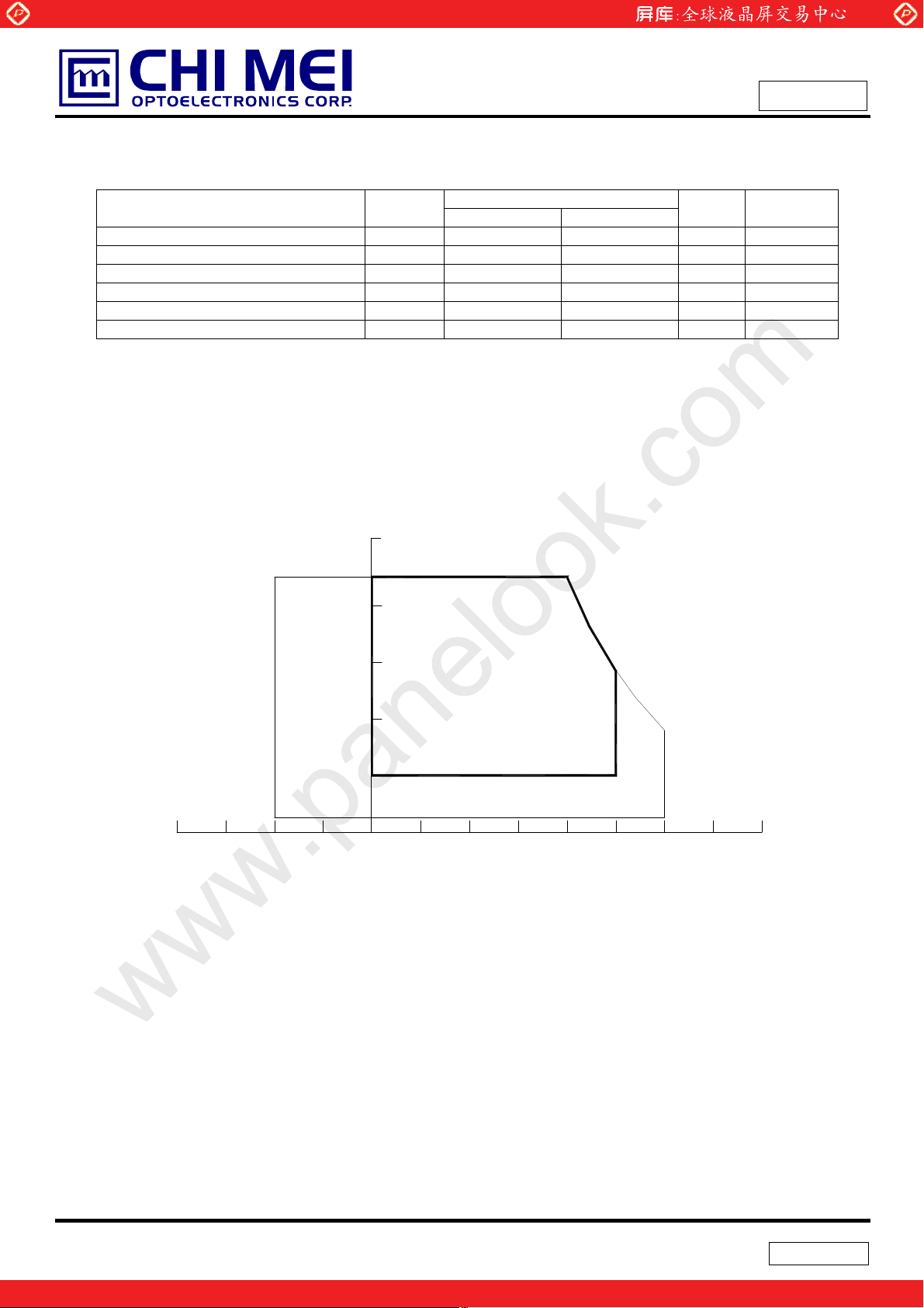
2.1 ABSOLUTE RATINGS OF ENVIRONMENT
Item Symbol
Storage Temperature TST -20 +60 ºC (1)
Operating Ambient Temperature TOP 0 +50 ºC (1), (2)
Storage Humidity HST 5 85 % Operation Humidity HOP 20 85 % Shock (Non-Operating) S
Vibration (Non-Operating) V
Note (1) Temperature and relative humidity range is shown in the figure below.
(a) 85 %RH Max. (Ta Љ 40 ºC).
(b) Wet-bulb temperature should be 39 ºC Max. (Ta > 40 ºC).
(c) No condensation of water.
www.panelook.com
Issued Date:Jul.08’2002
Model No.: M150X2-L01
Approval
Value
Min. Max.
- 50 G (3), (5)
NOP
- 2 G (4), (5)
NOP
Unit Note
Relative Humidity (%RH)
100
85
80
60
Operating Range
40
20
Storage Range
5
Temperature (ºC)
8060 -20 400 20-40
Note (2) The temperature of panel surface should be 0 ºC Min. and 60 ºC Max.
Note (3) 6ms, 1 time each ±X,±Y and ±Z directions
Note (4) 10 ~ 500 Hz, 1 cycle/20min. 1.5mm max, 1 hour each X, Y and Z directions
Note (5) At testing Vibration and Shock, the fixture in holding the module has to be hard and rigid enough
so that the module would not be twisted or bent by the fixture.
6 / 25
.
One step solution for LCD / PDP / OLED panel application: Datasheet, inventory and accessory!
Version 3.1
www.panelook.com
Page 7
Global LCD Panel Exchange Center
2.2 ELECTRICAL ABSOLUTE RATINGS
2.2.1 TFT LCD MODULE
Item Symbol
Power Supply Voltage VDD -0.3 4.0 V
2.2.2 BACKLIGHT UNIT
Item Symbol
Lamp Voltage VL 599 732 V
Lamp Current IL 3.0 6.5 mA
Lamp Frequency FL 30 80 KHz
Note (1) Permanent damage to the device may occur if maximum values are exceeded. Function operation
should be restricted to the conditions described under Normal Operating Conditions.
www.panelook.com
Value
Min. Max.
Value
Min. Max.
Unit Note
Unit Note
Issued Date:Jul.08’2002
Model No.: M150X2-L01
Approval
(1), (2), IL = 6.0 mA
RMS
RMS
(1), (2)
Note (2) Specified values are for lamp (Refer to Section 3.2 for further information).
7 / 25
.
One step solution for LCD / PDP / OLED panel application: Datasheet, inventory and accessory!
Version 3.1
www.panelook.com
Page 8
Global LCD Panel Exchange Center
3. ELECTRICAL CHARACTERISTICS
3.1 TFT LCD MODULE
Parameter Symbol
Power Supply Voltage Vcc 3.0 3.3 3.6 V Rush Current I
White - 750 800 mA (3)a
Power Supply Current
LVDS Receiver Threshold
Terminating Resistor RT - 100 - Ohm -
Note (1) The module should be always operated within above ranges.
Note (2) Measurement Conditions:
Black - 510 550 mA (3)b
Vertical Stripe
“H” Level VIH - - 100 mV - Differential Input Voltage for
“L” Level V
www.panelook.com
Min. Typ. Max.
- - 1 A (2)
RUSH
-
-
-
-100 - - mV -
IL
- 570 600 mA (3)c
Value
Issued Date:Jul.08’2002
Model No.: M150X2-L01
Approval
Unit Note
+3.3V
R1
47K
Q1 2SK1475
FUSE
C3
1uF
VDD
(LCD Module Input)
(High to Low)
(Control Signal)
SW
+12V
C1
1uF
VR1
R2
1K
47K
0.01uF
Q2
2SK1470
C2
+3.3V
0.9 V
DD
0.1 VDD
GND
470Ӵs
8 / 25
.
One step solution for LCD / PDP / OLED panel application: Datasheet, inventory and accessory!
Version 3.1
www.panelook.com
Page 9
Global LCD Panel Exchange Center
Note (3) The specified power supply current is under the conditions at VDD =3.3V, Ta = 25 ± 2 ºC, DC
www.panelook.com
Issued Date:Jul.08’2002
Model No.: M150X2-L01
Approval
Current and f
a. White Pattern
c. Vertical Stripe Pattern
= 60 Hz, whereas a power dissipation check pattern below is displayed.
v
b. Black Pattern
Active Area
B
B
Active Area
R
B
R
G
R
B
R
G
R
R R
G
G
B
B
R
G
G
G
G
B
B
B
B
R
R
Active Area
3.2 BACKLIGHT UNIT Ta = 25 ± 2 ºC
Parameter Symbol
Lamp Input Voltage VL 599 666 732 V
Lamp Current IL 2.0 6.0 6.5 mA
Lamp Turn On Voltage VS
Operating Frequency FL 30 45 80 KHz (3)
Lamp Life Time LBL 50,000 - - Hrs (5)
Power Consumption PL - 15984 - mW (4), IL = 6.0 mA
Note (1) Lamp current is measured by utilizing a high frequency current meter as shown below:
Note (2) The voltage shown above should be applied to the lamp for more than 1 second after startup.
LCD
Module
HV (Pink/ Blue)
LV (White/ Black)
Min. Typ. Max.
- - 850 (25
- - 1050 (0
Value
1
2
Current Meter
Unit Note
o
C) V
o
C) V
I
RMS
RMS
(2)
RMS
(2)
RMS
= 6.0 mA
L
(1)
Inverter
A
Otherwise the lamp may not be turned on.
9 / 25
.
One step solution for LCD / PDP / OLED panel application: Datasheet, inventory and accessory!
Version 3.1
www.panelook.com
Page 10

Global LCD Panel Exchange Center
Note (3) The lamp frequency may generate interference with horizontal synchronous frequency from the
display, and this may cause line flow on the display. In order to avoid interference, the lamp
frequency should be detached from the horizontal synchronous frequency and its harmonics as far
as possible.
www.panelook.com
Issued Date:Jul.08’2002
Model No.: M150X2-L01
Approval
Note (4) P
Note (5) The lifetime of lamp is defined as the time when it continues to operate under the conditions at Ta
Note (6) The waveform of the voltage output of inverter must be area-symmetric and the design of the
= IL VL
L
= 25 2
(a) When the brightness becomes Љ 50% of its original value.
(b) When the effective ignition length becomes Љ 80% of its original value. (Effective ignition
inverter must have specifications for the modularized lamp. The performance of the Backlight,
such as lifetime or brightness, is greatly influenced by the characteristics of the DC-AC inverter for
the lamp. All the parameters of an inverter should be carefully designed to avoid generating too
much current leakage from high voltage output of the inverter. When designing or ordering the
inverter please make sure that a poor lighting caused by the mismatch of the Backlight and the
inverter (miss-lighting, flicker, etc.) never occurs. If the above situation is confirmed, the module
should be operated in the same manners when it is installed in your instrument.
o
C and IL =7.0mA
length is defined as an area that the brightness is less than 70% compared to the center point.)
until one of the following events occurs:
RMS
10 / 25
.
One step solution for LCD / PDP / OLED panel application: Datasheet, inventory and accessory!
Version 3.1
www.panelook.com
Page 11

Global LCD Panel Exchange Center
)
)
)
)
)
)
)
)
4. BLOCK DIAGRAM
4.1 TFT LCD MODULE
LVDS
INPUT
(Hirose DF14H-20P-1.25H)
INPUT CONNECTOR
LVD S
INPUT
DC
POWER
SUPPLY
www.panelook.com
TIMING
CONTROLLER
DC/DC CONVERTER &
REFERENCE VOLTAGE
GENERATOR
Issued Date:Jul.08’2002
Model No.: M150X2-L01
Approval
SCAN DRIVER IC
TFT LCD PANEL
(1024x3x768)
DATA DRIVER IC
LAMP CONNECTOR
4.2 BACKLIGHT UNIT
(JST BHSR-02VS-1)
BACKLIGHT UNIT
1 HV (Pink
2 LV (White
1 HV (Blue
2 LV (Black
1 HV (Pink
2 LV (White
1 HV (Blue
2 LV (Black
11 / 25
.
One step solution for LCD / PDP / OLED panel application: Datasheet, inventory and accessory!
Version 3.1
www.panelook.com
Page 12

Global LCD Panel Exchange Center
www.panelook.com
5. INPUT TERMINAL PIN ASSIGNMENT
5.1 TFT LCD MODULE
in No. Symbol Function Polarity Note
1 VDD Power Supply +3.3V(typical)
2 VDD Power Supply +3.3V(typical)
3 GND Ground
4 GND Ground
5 RX0- LVDS Differential Data Input Negative
6 RX0+ LVDS Differential Data Input Positive
7 GND Ground
8 RX1- LVDS Differential Data Input Negative
9 RX1+ LVDS Differential Data Input Positive
10 GND Ground
11 RX2- LVDS Differential Data Input Negative
12 RX2+ LVDS Differential Data Input Positive
13 GND Ground
14 RXCLK- LVDS Differential Data Input Negative
15 RXCLK+ LVDS Differential Data Input Positive
16 GND Ground
17 RX3- LVDS Differential Data Input Negative
18 RX3+ LVDS Differential Data Input Positive
19 GND GND
20 NC Reserved
(1)Connector Part No.: [Hirose] DF14H-20P-1.25H
Issued Date:Jul.08’2002
Model No.: M150X2-L01
Approval
(2)Matching socket Part No.: [Hirose] DF14-20S-1.25C
5.2 BACKLIGHT UNIT
Pin Symbol Description Color
1 HV1 High Voltage Pink/ Blue
2 LV Ground White/ Black
Note (1) Connector Part No.: BHSR-02VS-1 (JST) or equivalent
Note (2) Matching Connector Part No.: SM02B-BHSS-1-TB (JST) or equivalent
12 / 25
.
One step solution for LCD / PDP / OLED panel application: Datasheet, inventory and accessory!
Version 3.1
www.panelook.com
Page 13

Global LCD Panel Exchange Center
5.3 COLOR DATA INPUT ASSIGNMENT
The brightness of each primary color (red, green and blue) is based on the 8-bit gray scale data input for
the color. The higher the binary input the brighter the color. The table below provides the assignment of
color versus data input.
Color
R7 R6 R5 R4 R3 R2 R1 R0 R7 R6 G5 G4 G3 G2 G1 G0 R7 R6 B5 B4 B3 B2 B1 B0
Basic
Colors
Gray
Scale
Of
Red
Black
Red
Green
Blue
Cyan
Magenta
Ye ll ow
White
Red(0) / Dark
Red(1)
Red(2)
:
:
Red(252)
Red(252)
Red(252)
0
1
0
0
0
1
1
1
0
0
0
1
1
1
0
0
1
1
0
0
0
0
0
0
1
1
1
1
1
1
0
0
0
0
0
0
:
:
:
:
1
1
1
1
1
1
www.panelook.com
Issued Date:Jul.08’2002
Model No.: M150X2-L01
Approval
Data Signal
Red Green Blue
0
0
0
0
0
0
0
0
0
0
0
0
0
0
0
0
0
0
0
0
0
1
1
1
1
1
0
0
0
0
0
0
0
0
0
0
0
0
0
0
0
0
0
0
0
0
0
1
1
1
1
1
1
1
1
0
0
0
0
0
0
0
0
0
0
0
0
0
0
0
0
0
0
0
0
0
1
1
1
1
1
1
1
1
0
0
0
0
0
1
1
1
1
1
1
1
1
1
1
1
1
1
1
1
1
1
1
1
1
1
0
0
0
0
0
0
0
0
1
1
1
1
1
1
1
1
1
1
1
1
1
1
1
1
1
1
1
1
1
0
0
0
0
0
0
0
0
1
1
1
1
1
1
1
1
1
1
1
1
1
1
1
1
1
1
1
1
1
0
0
0
0
0
0
0
0
0
0
0
0
0
0
0
0
0
0
0
0
0
0
0
0
0
1
0
0
0
0
0
0
0
0
0
0
0
0
0
0
0
0
0
0
0
1
0
0
0
0
0
0
0
0
0
0
0
0
0
0
0
0
0
:
:
:
:
:
:
:
:
:
:
:
:
:
:
:
:
:
:
:
:
:
:
:
:
:
:
:
:
:
:
:
:
:
:
:
:
:
:
:
:
:
:
:
:
1
1
1
0
1
0
0
0
0
0
0
0
0
0
0
0
0
0
0
0
0
1
1
1
1
0
0
0
0
0
0
0
0
0
0
0
0
0
0
0
0
0
1
1
1
1
1
0
0
0
0
0
0
0
0
0
0
0
0
0
0
0
0
Green(0)/Dark
Gray
Scale
Of
Green
Gray
Scale
Of
Blue
Note (1) 0: Low Level Voltage, 1: High Level Voltage
Green(1)
Green(2)
:
:
Green(252)
Green(252)
Green(252)
Blue(0) / Dark
Blue(1)
Blue(2)
:
:
Blue(252)
Blue(252)
Blue(252)
0
0
0
0
0
0
0
0
0
0
0
0
0
0
0
0
0
0
0
0
0
0
0
0
0
0
0
0
0
0
:
:
:
:
:
:
:
:
:
:
:
:
:
:
0
0
0
0
0
0
0
0
0
0
0
0
0
0
0
0
0
0
0
0
0
0
0
0
0
0
0
0
0
0
0
0
0
0
0
0
:
:
:
:
:
:
:
:
:
:
:
:
:
:
0
0
0
0
0
0
0
0
0
0
0
0
0
0
0
0
0
0
0
0
0
0
0
0
0
0
0
0
0
0
0
0
0
0
0
0
0
0
0
0
0
0
0
1
0
0
0
0
0
0
0
0
0
0
0
0
0
0
0
1
0
0
0
0
0
0
0
0
0
:
:
:
:
:
:
:
:
:
:
:
:
:
:
:
:
:
:
:
:
:
:
:
:
:
:
:
:
:
:
:
:
:
:
0
1
1
1
1
1
1
0
1
0
0
0
0
0
0
0
0
0
1
1
1
1
1
1
1
0
0
0
0
0
0
0
0
0
0
1
1
1
1
1
1
1
1
0
0
0
0
0
0
0
0
0
0
0
0
0
0
0
0
0
0
0
0
0
0
0
0
0
0
0
0
0
0
0
0
0
0
0
0
0
0
0
0
0
1
0
0
0
0
0
0
0
0
0
0
0
0
0
0
0
1
0
:
:
:
:
:
:
:
:
:
:
:
:
:
:
:
:
:
:
:
:
:
:
:
:
:
:
:
:
:
:
:
:
:
:
0
0
0
0
0
0
0
0
0
1
1
1
1
1
1
0
1
0
0
0
0
0
0
0
0
0
1
1
1
1
1
1
1
0
0
0
0
0
0
0
0
0
0
1
1
1
1
1
1
1
1
13 / 25
.
One step solution for LCD / PDP / OLED panel application: Datasheet, inventory and accessory!
Version 3.1
www.panelook.com
Page 14

Global LCD Panel Exchange Center
6. INTERFACE TIMING
6.1 INPUT SIGNAL TIMING SPECIFICATIONS
The input signal timing specifications are shown as the following table and timing diagram.
Signal Parameter Symbol Min Typ Max Unit Remarks
DCLK
Ver t ical
Horizontal
Pixel clock Frequency Fck - 65 80 MHz
Pixel clock period Tck 12.5 15 20 ns
Duty ratio (%Tch) - 45 50 55 % Tch/Tck
High time Tckh 5 - - ns
Low time Tckl 5 - - ns
Setup time Tsd 4 - - ns DATA
Hold time Thd 4 - - ns
Setup time Tsde 4 - - ns DE
Hold time Thde 4 - - ns
Vertical Frequency Fv - 60 75 Hz
Vertical display active period Tvda 768 768 768 Thp
Vertical display blank period Tvdb 1 38 - Thp
Vertical period Tvp 769 806 - Thp
Horizontal display active
period
Horizontal display blank period
Horizontal period
www.panelook.com
Thda 1024 1024 1024 Tck
Thdb 76 320 776 Tck
Thp
1100 1344 1800
Tck
Issued Date:Jul.08’2002
Model No.: M150X2-L01
Approval
Note (1) Because this module is operated by DE only mode, Hsync and Vsync input signals should be
set to low logic level or ground. Otherwise, this module would operate abnormally.
14 / 25
.
One step solution for LCD / PDP / OLED panel application: Datasheet, inventory and accessory!
Version 3.1
www.panelook.com
Page 15

Global LCD Panel Exchange Center
www.panelook.com
Issued Date:Jul.08’2002
Model No.: M150X2-L01
Approval
INPUT SIGNAL TIMING DIAGRAM
DE
DE
DCLK
DATA
768
Tvdb
1
Thdb
Valid display data (1024 Tck)
Thp
Tvp
Tvda
2
Thda
768
Invalid Valid
DCLK
DATA
DE
Tck h
Tck l
Tch
Tsde
Tck
0.7VDD
0.3VDD
Thd Tsd
0.7VDD
0.3VDD
Thde
0.7VDD
15 / 25
.
One step solution for LCD / PDP / OLED panel application: Datasheet, inventory and accessory!
Version 3.1
www.panelook.com
Page 16

Global LCD Panel Exchange Center
www.panelook.com
Issued Date:Jul.08’2002
Model No.: M150X2-L01
Approval
TIMING DIAGRAM of LVDS
TxCLK OUT
RxCK IN
Rx IN3
Rx IN2
Rx IN1
Rx IN0
T
T/7
RxOUT23
RxOUT17
RxOUT16 RxOUT11 RxOUT10
RESERVED B07 B06 G07 G06 R07 R06
RxOUT26
RxOUT25 RxOUT24 RxOUT22
RxOUT21
DE GND GND B05 B04 B03 B02
RxOUT18
RxOUT15 RxOUT14 RxOUT13
RxOUT12
B01 B00 G05 G04 G03 G02 G01
RxOUT7 RxOUT6
RxOUT4
RxOUT3 RxOUT2
G00 R05 R04 R03 R02 R01 R00
RxOUT5
RxOUT20
RxOUT9
RxOUT1
RxOUT27
RxOUT19
RxOUT8
RxOUT0
16 / 25
.
One step solution for LCD / PDP / OLED panel application: Datasheet, inventory and accessory!
Version 3.1
www.panelook.com
Page 17

Global LCD Panel Exchange Center
6.2 POWER ON/OFF SEQUENCE
www.panelook.com
Issued Date:Jul.08’2002
Model No.: M150X2-L01
Approval
Power Supply
for LCD, Vcc
- Interface Signal
(LVDS Signal of
Transmitter), V
- Power for Lamp
Timing Specifications:
0 < t1 Љ 10 msec
0 < t2 Љ 50 msec
0 < t3 Љ 50 msec
Restart
Power On
90%
0V
0V
I
10%
t1
Valid Data
ONOFF OFF
Power Off
90%
t3 t2
t6 t5
10%
t4
10%
t4 Њ 1 sec
t5 Њ 100 msec
t6 Њ 100 msec
Note (1) Please avoid floating state of interface signal at invalid period.
Note (2) When the interface signal is invalid, be sure to pull down the power supply of LCD V
to 0 V.
DD
Note (3) The Backlight inverter power must be turned on after the power supply for the logic and the
interface signal is valid. The Backlight inverter power must be turned off before the power supply
for the logic and the interface signal is invalid.
17 / 25
.
One step solution for LCD / PDP / OLED panel application: Datasheet, inventory and accessory!
Version 3.1
www.panelook.com
Page 18

Global LCD Panel Exchange Center
7. OPTICAL CHARACTERISTICS
7.1 TEST CONDITIONS
Item Symbol Value Unit
Ambient Temperature Ta
Ambient Humidity Ha
Supply Voltage VCC 5.0 V
Input Signal According to typical value in "3. ELECTRICAL CHARACTERISTICS"
Inverter Current IL 6.0 mA
The measurement methods of optical characteristics are shown in Section 7.2. The following items
should be measured under the test conditions described in Section 7.1 and stable environment shown in
Note (4).
7.2 OPTICAL SPECIFICATIONS
Item Symbol Condition Min. Typ. Max. Unit Note
Contrast Ratio CR 300 400 - - (2), (4)
Response Time
Center Luminance of White L 210 250 - cd/m
Red
Color
Chromaticity
Viewing Angle
Green
Blue
White
Horizontal
Ver t ical
www.panelook.com
Issued Date:Jul.08’2002
Model No.: M150X2-L01
Approval
o
25r2
50r10
TR - 15 30 ms
- 10 25 ms
T
F
Rx 0.610 0.640 0.670 Ry 0.328 0.358 0.388 Gx 0.262 0.292 0.322 -
=0q, TY =0q
T
x
Viewing Normal Angle
Gy 0.565 0.595 0.625 Bx 0.118 0.148 0.178 By 0.091 0.121 0.151 -
Wx 0.280 0.310 0.340 Wy
Tx+
T
x
TY+
T
Y
CRt10
-
0.300 0.330 0.360 80 - 80 - 80 - 80 - -
C
%RH
Deg.
2
(3)
(4)
(1), (4)
.
18 / 25
Version 3.1
One step solution for LCD / PDP / OLED panel application: Datasheet, inventory and accessory!
www.panelook.com
Page 19

Global LCD Panel Exchange Center
T
Note (1) Definition of Viewing Angle (Tx, Ty):
www.panelook.com
Issued Date:Jul.08’2002
Model No.: M150X2-L01
Approval
TX- = 90º
x-
6 o’clock
T
y- = 90º
y-
Note (2) Definition of Contrast Ratio (CR):
The contrast ratio can be calculated by the following expression.
Normal
Tx = Ty = 0º
Ty- Ty
Tx-
Tx
y+
12 o’clock direction
T
y+ = 90º
x+
TX+ = 90º
Contrast Ratio (CR) = L63 / L0
L63: Luminance of gray level 63
L 0: Luminance of gray level 0
CR = CR (5)
CR (X) is corresponding to the Contrast Ratio of the point X at Figure in Note (5).
Note (3) Definition of Response Time (T
100%
90%
Optical
Response
Gray Level 255
10%
0%
, TF):
R
Gray Level 255
Gray Level 0
ime
T
T
F
R
19 / 25
.
One step solution for LCD / PDP / OLED panel application: Datasheet, inventory and accessory!
Version 3.1
www.panelook.com
Page 20

Global LCD Panel Exchange Center
Note (4) Measurement Setup:
The LCD module should be stabilized at given temperature for 20 minutes to avoid abrupt
temperature change during measuring. In order to stabilize the luminance, the measurement
should be executed after lighting Backlight for 20 minutes in a windless room.
LCD Module
www.panelook.com
Issued Date:Jul.08’2002
Model No.: M150X2-L01
Approval
LCD Panel
Center of the Screen
Field of View = 2º
500 mm
Photometer
(TOPCON BM-5A)
Light Shield Room
(Ambient Luminance < 2 lux)
.
20 / 25
Version 3.1
One step solution for LCD / PDP / OLED panel application: Datasheet, inventory and accessory!
www.panelook.com
Page 21

Global LCD Panel Exchange Center
8. PRECAUTIONS
8.1 HANDLING PRECAUTIONS
(1) The module should be assembled into the system firmly by using every mounting hole. Be careful not
to twist or bend the module.
(2) While assembling or installing modules, it can only be in the clean area. The dust and oil may cause
electrical short or damage the polarizer.
(3) Use fingerstalls or soft gloves in order to keep display clean during the incoming inspection and
assembly process.
(4) Do not press or scratch the surface harder than a HB pencil lead on the panel because the polarizer is
very soft and easily scratched.
(5) If the surface of the polarizer is dirty, please clean it by some absorbent cotton or soft cloth. Do not use
Ketone type materials (ex. Acetone), Ethyl alcohol, Toluene, Ethyl acid or Methyl chloride. It might
www.panelook.com
Issued Date:Jul.08’2002
Model No.: M150X2-L01
Approval
permanently damage the polarizer due to chemical reaction.
(6) Wipe off water droplets or oil immediately. Staining and discoloration may occur if they left on panel for
a long time.
(7) If the liquid crystal material leaks from the panel, it should be kept away from the eyes or mouth. In
case of contacting with hands, legs or clothes, it must be washed away thoroughly with soap.
(8) Protect the module from static electricity, it may cause damage to the C-MOS Gate Array IC.
(9) Do not disassemble the module.
(10) Do not pull or fold the lamp wire.
(11) Pins of I/F connector should not be touched directly with bare hands.
8.2 STORAGE PRECAUTIONS
(1) High temperature or humidity may reduce the performance of module. Please store LCD module within
the specified storage conditions.
(2) It is dangerous that moisture come into or contacted the LCD module, because the moisture may
damage LCD module when it is operating.
(3) It may reduce the display quality if the ambient temperature is lower than 10 ºC. For example, the
response time will become slowly, and the starting voltage of lamp will be higher than the room
temperature.
8.3 OPERATION PRECAUTIONS
(1) Do not pull the I/F connector in or out while the module is operating.
(2) Always follow the correct power on/off sequence when LCD module is connecting and operating. This
can prevent the CMOS LSI chips from damage during latch-up.
(3) The startup voltage of Backlight is approximately 1000 Volts. It may cause electrical shock while
assembling with inverter. Do not disassemble the module or insert anything into the Backlight unit.
21 / 25
.
One step solution for LCD / PDP / OLED panel application: Datasheet, inventory and accessory!
Version 3.1
www.panelook.com
Page 22

Global LCD Panel Exchange Center
9. PACKAGING
9.1 PACKING SPECIFICATIONS
(1) 5 LCD modules / 1 Box
(2) Box dimensions : 353(L) X 268(W) X 462(H) mm
www.panelook.com
Issued Date:Jul.08’2002
Model No.: M150X2-L01
Approval
(3) Weight : approximately 8.5Kg ( 5 modules per box)
9.2 PACKING Method
Figures 9-1and 9-2 are the packing method.
Figure. 9-1 Packing method
22 / 25
.
One step solution for LCD / PDP / OLED panel application: Datasheet, inventory and accessory!
Version 3.1
www.panelook.com
Page 23

Global LCD Panel Exchange Center
www.panelook.com
Issued Date:Jul.08’2002
Model No.: M150X2-L01
Approval
Figure. 9-2 Packing method
23 / 25
.
One step solution for LCD / PDP / OLED panel application: Datasheet, inventory and accessory!
Version 3.1
www.panelook.com
Page 24

Global LCD Panel Exchange Center
www.panelook.com
Issued Date:Jul.08’2002
Model No.: M150X2-L01
Approval
10. INCOMING INSPECTION DAY
The Supplier should be acquainted the inspection results (acceptance or rejection) by Customer, and the results
are in accordance with the incoming inspection standard within 30 days after the date of the bills of lading.
Should Customer fail to so notify the Supplier within the said 30 days period. The Customer’s right to reject the
LCMS shall then lapse, and the said LCMS shall be deemed to have been accepted by the customer.
24 / 25
.
One step solution for LCD / PDP / OLED panel application: Datasheet, inventory and accessory!
Version 3.1
www.panelook.com
Page 25

Global LCD Panel Exchange Center
11. DEFINITION OF LABELS
11.1 CMO MODULE LABEL
The barcode nameplate is pasted on each module as illustration, and its definitions are as following
explanation.
CHI MEI
OPTOELECTRONICS
(a) Model Name: M150X2 –L01
(b) Revision: Rev. XX, for example: C1, C2 …etc.
www.panelook.com
M150X2 -L01 Rev. XX
MADE IN TAIWAN
X X X X X X X Y M D L N N N N
Issued Date:Jul.08’2002
Model No.: M150X2-L01
Approval
E207943
MADE IN TAIWAN
(c) Serial ID: X X
Serial ID includes the information as below:
(a) Manufactured Date: Year: 1~9, for 2000~2009
Day: 1~9, A~Y, for 1
(b) Revision Code: cover all the change
(c) Color Filter: 0 ->CMO, 2 -> Toppan
X X X X X Y M D L N N N N
Month: 1~9, A~C, for Jan. ~ Dec.
Serial No.
Product Line
Year, Month, Date
CMO Internal Use
Color Filter
Revision
CMO Internal Use
st
to 31st, exclude I and O
(d) Serial No.: Manufacturing sequence of product
(e) Product Line: 1 -> Line1, 2 -> Line 2, …etc.
25 / 25
.
One step solution for LCD / PDP / OLED panel application: Datasheet, inventory and accessory!
Version 3.1
www.panelook.com
Page 26

Page 27

HIGH VOLTAGE
CAUTION
Page 28

Global LCD Panel Exchange Center
Document No.:
Issue Date: 2002/05/09
VERSION: 1.0 C
www.panelook.com
LCD Module Inspection Specification
1
Address: No. 1, Chi-Yeh Road, Hsin-Shih Village,Tainan Science-Based Industrial Park,Tainan County, Taiwan 744 R.O.C.
TEL: 886-6-5051888
Inspection Specification
One step solution for LCD / PDP / OLED panel application: Datasheet, inventory and accessory!
www.panelook.com
Page 29

Global LCD Panel Exchange Center
Document No.:
Issue Date: 2002/05/09
VERSION: 1.0 C
www.panelook.com
Revision History
Version Date Page Section Description
Ver. 1.0C May 09’02 5 6.(3)
Ver. 1.0C May 09’02 5 6.(3)
Ver. 1.0C May 09’02 5 6.(3)
Ver. 1.0C May 09’02 5 6.(3)
Ver. 1.0C May 09’02 5 6.(3)
Foreign black/white spots: 0.1ɦDɩ0.5 mm, Nɩ2
Foreign lint: 0.01ɦWɩ0.08 mm, 0.3ɦLɩ1.0
mm, Nɩ2
Polarizer Scratches: 0.01ɦWɩ0.1 mm 0.3ɦLɩ
10.0 mm, Nɩ2
Dent/Air bubble: Avg. Dɩ0.5 mm, Nɩ2
Max.: Nɩ10
2
Address: No. 1, Chi-Yeh Road, Hsin-Shih Village,Tainan Science-Based Industrial Park,Tainan County, Taiwan 744 R.O.C.
TEL: 886-6-5051888
Inspection Specification
One step solution for LCD / PDP / OLED panel application: Datasheet, inventory and accessory!
www.panelook.com
Page 30

Global LCD Panel Exchange Center
www.panelook.com
Document No.:
Issue Date: 2002/05/09
VERSION: 1.0 C
Inspection
Standards for LCD Modules
1.Description
These inspection standards shall be applied to LCD Module supplied by CHI MEI Optoelectronics
Corporation.
2.The environmental condition of inspection
The environmental condition and visual inspection shall be conducted as below.
(1) Ambient temperature : 15~25ʚ
(2) Humidity: 25~75 %RH
(3) External appearance inspection shall be conducted by using a single 20W fluorescent lamp or
equivalent illumination.
(4) Panel visual inspection on the operation condition for cosmetic shall be conducted at the distance
35cm or more between the LCD module and eyes of inspector. And, the viewing angle shall be 90
degree to the front surface of display panel.
Ambient Illumination: 300 ~ 600Lux for external appearance inspection
Ambient Illumination: 100 ~ 200 Lux for light on inspection
3.Method of sampling inspection
Unless defined in the other document, the sampling method shall be in accordance with
MIL-STD-105E.
(1) Lot size: quantity of per delivery for inspection per model.
(2) Sampling type: Normal inspection, Single sampling
(3) Inspection level: level II
(4) Sampling table: MIL-STD-105E
4.Classification of defects
Defects are classified two types, major defect and minor defect according to the defect. And, the
definition of defects is classified as below.
(1) Major defect
Any defect may result in functional failure, or reduce the usability of product for its purpose. For
example, electrical failure, deformation and etc..
(2) Minor defect
A defect that is not to reduce the usability of product for its intended purpose and un-uniformity, dot
defect and etc..
3
Address: No. 1, Chi-Yeh Road, Hsin-Shih Village,Tainan Science-Based Industrial Park,Tainan County, Taiwan 744 R.O.C.
TEL: 886-6-5051888
Inspection Specification
One step solution for LCD / PDP / OLED panel application: Datasheet, inventory and accessory!
www.panelook.com
Page 31

Global LCD Panel Exchange Center
www.panelook.com
Document No.:
Issue Date: 2002/05/09
VERSION: 1.0 C
The criteria on major and/or minor judgement will be according with the classification of defects.
5.Acceptable quality level (AQL)
AQL means that the quality level of product is acceptable for shipment, and the AQL shall satisfy
with customer’s quality request.
The AQL (%) for major or minor defect are expressed as below respectively.
(1) Major defect: 0.65
(2) Minor defect: 1.0
6.Inspection Criteria
(1) Definition of dot defect
a) The definition of dot: The size of a defective dot over 1/2 of whole dot is regarded as one defective
dot.
b) Bright dot: Dots appear bright and unchanged in size in which module is displaying
under black pattern.
c) Dark dot: Dots appear dark and unchanged in size in which module is displaying
under pure red ,green , blue picture.
d) 2 dot adjacent = 1pair = 2 dots
4
Address: No. 1, Chi-Yeh Road, Hsin-Shih Village,Tainan Science-Based Industrial Park,Tainan County, Taiwan 744 R.O.C.
TEL: 886-6-5051888
Inspection Specification
One step solution for LCD / PDP / OLED panel application: Datasheet, inventory and accessory!
www.panelook.com
Page 32

Global LCD Panel Exchange Center
b
www.panelook.com
Document No.:
Issue Date: 2002/05/09
VERSION: 1.0 C
(2) Electrical Inspection
Items Acceptable count
Nɩ2
Nɩ1
Nɩ0
Nɩ5
Nɩ1
Nɩ0
Lɪ15mm
Bright dot
Dark dot
Random
2 dots adjacent
3 dots adjacent or more
Random
2 dots adjacent
3 dots adjacent or more
Minimum Distance Between Bright dots
Distance
Minimum Distance Between Dark dots
Total bright and dark spot
Lɪ5mm
Nɩ7
Display failure (V-line/H-line/Cross line etc.) Not allowable
(3) Appearance inspection
Item Standards
Foreign black/white spots
Foreign lint
Polarizer Scratches
Dent/Air bubble
Max.
0.1ɦDɩ0.5 mm, Nɩ2
0.01ɦWɩ0.08 mm, 0.3ɦLɩ1.0 mm, Nɩ2
0.01ɦWɩ0.1 mm 0.3ɦLɩ10.0 mm, Nɩ2
Avg. D ɩ0.5 mm, Nɩ2
Nɩ10
a
L
W
D=(a+b)/2 W: width, LΚlength
5
Address: No. 1, Chi-Yeh Road, Hsin-Shih Village,Tainan Science-Based Industrial Park,Tainan County, Taiwan 744 R.O.C.
TEL: 886-6-5051888
Inspection Specification
One step solution for LCD / PDP / OLED panel application: Datasheet, inventory and accessory!
www.panelook.com
Page 33

Global LCD Panel Exchange Center
www.panelook.com
Document No.:
Issue Date: 2002/05/09
VERSION: 1.0 C
7.Classification of defects
Inspection Item Criteria and Description Defect type
Vertical line Signal input, vertical line off or abnormal V-line appears major
Horizontal line Signal input, horizontal line off or abnormal H-line appears major
Cross line Pattern signal input, a correct display is not obtained major
No display Signal input, display is dead major
Abnormal display Pattern signal input, a correct display is not obtained major
Bezel finger Bezel finger is missed or not bent major
Outline size Length, Wide, High, CCFT cable length major
Dots defect Exceed specified standards minor
Light leakage Visible light leakage appears around the edges of screen minor
Foreign material Exceed specified standards minor
Mura
External Appearance
The specific mura can be judged by limit sample in agreement
with each other.
Rust, deformation, irregular plating, coating missing etc.
A appearance defect that do not affect function or performance
Polarizer bubble Exceed specified standards minor
minor
minor
6
Address: No. 1, Chi-Yeh Road, Hsin-Shih Village,Tainan Science-Based Industrial Park,Tainan County, Taiwan 744 R.O.C.
TEL: 886-6-5051888
Inspection Specification
One step solution for LCD / PDP / OLED panel application: Datasheet, inventory and accessory!
www.panelook.com
 Loading...