

Page 1
Global LCD Panel Exchange Center
A
Model No: M141X102
www.panelook.com
Doc.No:14005207
Issue Date: MAY.15,2000
Model: M141X102
APPROVAL
TFT-LCD Specification
Customer : .
pproved by :
Note :
Liquid Crystal Division
QRA Dept. RD Dept. System Dept.
Approval Approval Approval
1/22
Version 2.0
One step solution for LCD / PDP / OLED panel application: Datasheet, inventory and accessory!
www.panelook.com
Page 2
Global LCD Panel Exchange Center
CONTENTS
REVISION HISTORY
GENERAL DESCRIPTION
1. ABSOLUTE MAXIMUM RATINGS
2. ELECTRICAL SPECIFICATIONS
www.panelook.com
Doc.No:14005207
Issue Date: MAY.15,2000
Model: M141X102
APPROVAL
3. INTERFACE SPECIFICATIONS
3.1 THE PIN ASSIGNMENT OF TTL INTERFACE CONNECTOR
3.2 INPUT SIGNAL TIMING SPECIFICATIONS
3.3 COLOR DATA INPUT ASSIGNMENT
3.4 POWER UP/DOWN SEQUENCE
4. OPTICAL SPECIFICATIONS
5. Reliability Test Item
6. MECHNICAL DRAWINGS
7. PRECAUTION
7.1 ASSEMBLY AND HANDLING PRECAUTION
7.2 SAFTY PRECAUTION
8. PACKAGING
8.1 PACKING SPECIFICATIONS
8.2 PACKING METHOD
9. INCOMING INSPECTION DAY
10. DEFINITION OF SHIPPING LABEL ON MODULE
2/22
Version 2.0
One step solution for LCD / PDP / OLED panel application: Datasheet, inventory and accessory!
www.panelook.com
Page 3
Global LCD Panel Exchange Center
VERSION Date DESCPIPTION
Ver 1.0
Sep.10.’99
www.panelook.com
Doc.No:14005207
Issue Date: MAY.15,2000
Model: M141X102
APPROVAL
REVISION HISTORY
Issue Preliminary Specification.
Ver 2.0
May.15.’00
Issue Approval Specification.
3/22
Version 2.0
One step solution for LCD / PDP / OLED panel application: Datasheet, inventory and accessory!
www.panelook.com
Page 4
Global LCD Panel Exchange Center
p
(
)
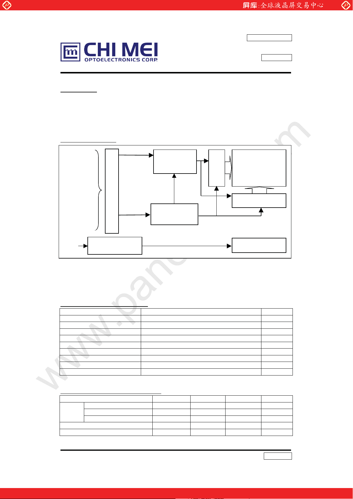
GENERAL DESCRIPTION
OVERVIEW
This product is a 14.1” TFT Liquid Crystal Display Module with a 2 lamps Backlight unit and 60
pins TTL interface. This module supports 1024 x 768 XGA mode and can display 262,144
colors. The inverter module for Backlight is not built in.
BLOCK DIAGRAM
In
HSYNC
VSYNC
ENAB
DCLK
RE0~5
GE0~5
BE0~5
RO0~5
GO0~5
Vcc
BO0~5
V
CC
GND
ut Connector
Molex- 52760-0600
www.panelook.com
Timing Control
ASIC
DC/DC Converter
& Reference
Voltage Generator
Doc.No:14005207
Issue Date: MAY.15,2000
Model: M141X102
APPROVAL
Scan Driver IC
TFT-LCD Panel
(1024x768x3)
Data Driver IC
VL
Lamp Connector
( JST-BHR-03VS-1)
Backlight Unit
APPLICATION
-TFT-LCD Monitor
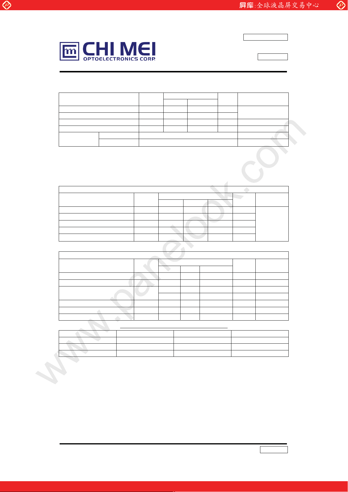
GENERAL SPECIFICATI0NS
Item Specifications Unit
Screen Size 14.1 Diagonal inch
Bezel opening area 289.8(W)x218.4(H) mm
Effective display area 285.7(W)x214.3(H) mm
Pixel number 1024 x R.G.Bx768 pixel
Pixel pitch 0.279(H)x0.279(V) mm
Pixel Arrangement R.G.B Vertical Stripe Display Color 6 bits, 262,144 color
Transmissive mode Normally white Surface treatments Hard coating(3H) and anti-glare -
MECHANICAL SPECIFICATIONS
ITEM MIN. TYP. MAX. Unit
Module
size
Gap, panel surface with metal frame - - 0.5 mm
Horizontal 329.5 330 330.5 mm
Vertical 254.5 255 255.5 mm
Depth - 17.0 17.5 mm
Weight - 1250 1300 g
4/22
Version 2.0
One step solution for LCD / PDP / OLED panel application: Datasheet, inventory and accessory!
www.panelook.com
Page 5
Global LCD Panel Exchange Center
1. ABSOLUTE MAXIMUM RATINGS
www.panelook.com
Doc.No:14005207
Issue Date: MAY.15,2000
Model: M141X102
APPROVAL
Parameter Symbol
Min. Max.
Values
Unit Remarks
Power supply voltage VCC -0.3 +6.0 V
Logic input voltage VIN -0.3 VCC+0.3 V
Ta=25ºC
Operating temperature Top 0 +50 ºC Module surface*
Storage temperature Tst -20 +60 ºC -
Humidity
Operation 20%~95% relative humidity Ta<=40ºC
Non operation 5%~95% relative humidity Ta<=40ºC
*Measure at the active display area
2. ELECTRICAL SPECIFICATIONS
MODULE
Parameter Symbol
Min. Typ. Max.
Power Supply Voltage VCC 4.5 5.0 5.5 V
Power Supply Current l
140 290 600 mA
CC
Ripple voltage VRP - 50 - mV
“H” level logical input voltage VIH 2 - Vcc V
“L” level logical input voltage VIL Vss - 1 V
Parameter Symbol
Min. Typ. Max.
Lamp Voltage VL 560 630 700 V
Lamp Current IL 1.0 6.0 8.0 mA 2
Startup Voltage V
Operating Frequency
Power Consumption
S
F
30 50 70 KHz 4
L
P
6.8 7.6 8.4 W 5, IL=6.0mA
L
- - 1255 (25oC) V
- - 1385 (0 oC) V
Lamp Life time LBL 50000 - - Hrs 6
The connector information of Black light unit.
Pin Symbol Description Remark
1 HV Lamp power input White
2 NC No connect
3 LV Ground Black
Connector Part No.: BHR-03VS-1 (JST)
User’s connector Part No.: SM02 (8.0) B-BHS-1-TB (JST)
Value
Unit Notes
1
BACKLIGHT ( 2 Lamps) Ta=252oC
Value
Unit Notes
IL=6.0mA
RMS
3
RMS
3
RMS
5/22
Version 2.0
One step solution for LCD / PDP / OLED panel application: Datasheet, inventory and accessory!
www.panelook.com
Page 6
Global LCD Panel Exchange Center
R
G
R
GBR
G
R
G
R
GBR
G
R
G
R
GBR
G
R
G
R
GBR
G
R
G
R
GBR
G
R
G
R
GBR
G
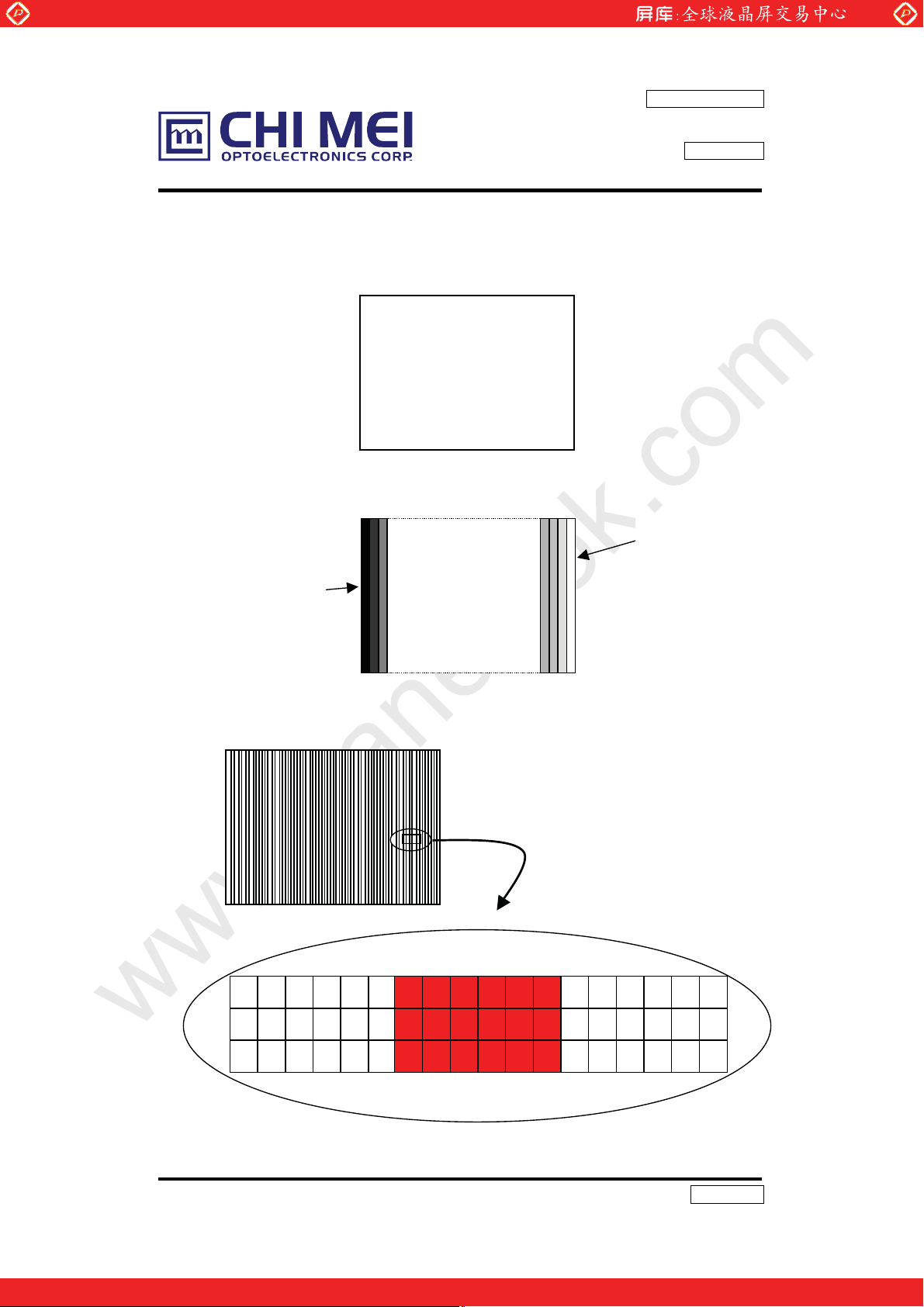
Note1: Operating Temperature range : 0 ~ 50 ºC.
Power Supply Current specifications are tested by the following test pattern.
(a) Minimal value test pattern : White pattern
www.panelook.com
Doc.No:14005207
Issue Date: MAY.15,2000
Model: M141X102
APPROVAL
Gray 63
(b)Typical value test pattern : 64 gray scale pattern
Gray 0
(C) Maximal value test pattern : Vertical 2 pixel white/black pattern
Gray 63
B
B
B
B
B
B
B
B
B
B
6/22
Version 2.0
One step solution for LCD / PDP / OLED panel application: Datasheet, inventory and accessory!
B
B
www.panelook.com
Page 7
Global LCD Panel Exchange Center
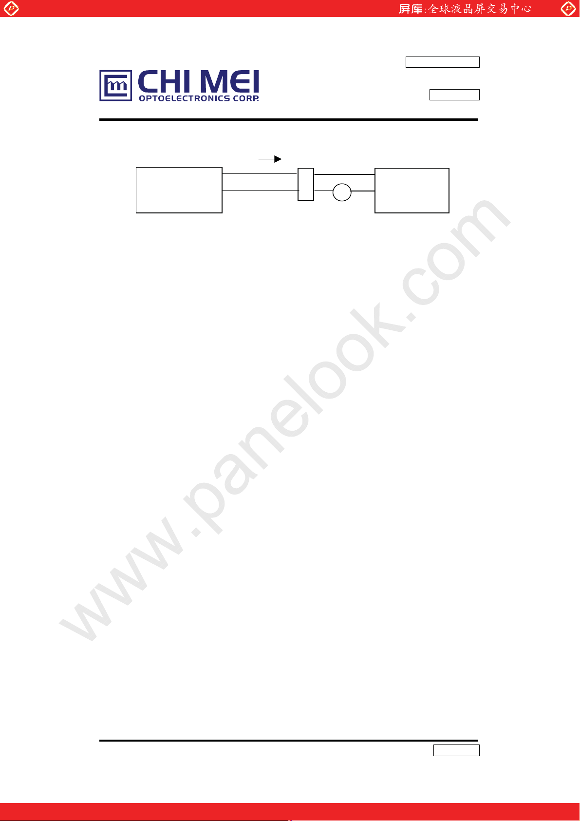
Note 2: Lamp current is measured by utilizing a current meter for high frequency as shown
below:
www.panelook.com
Doc.No:14005207
Issue Date: MAY.15,2000
Model: M141X102
APPROVAL
HV(Whit
LCD
Module
Note 3: The voltage shown above should be applied to the lamp for more than 1 second after
startup. Otherwise the lamp may not be turned on. And the start voltage at 0ºC is the
condition that stabilizes in the lamp, and it is the value that guarantees the lighting of
the lamp.
Note 4: The lamp frequency may produce interference with horizontal synchronous frequency
from the display, and this may cause line flow on the display. In order to avoid
interference the lamp frequency should be detached from the horizontal synchronous
frequency and its harmonics as far as possible.
.
Note 5: P
Note 6: The lifetime (Hr) of a lamp can be defined as the time in which it continues to operate
under the condition Ta = 252
= ILVL2.
L
LV ( Bl a c k))
o
C and IL = 6.0 mArms until one of the following event
e)
1
2
Current meter
A
Inverter
occurs:
(1) When the brightness becomes 50% or lower than its original,
(2) When the effective ignition length becomes 80% or lower than its original value.
(Effective ignition length is defined as an area that has less than 70% brightness
compared to the brightness in the center point.)
Note 7: The waveform of the voltage output of inverter must be area-symmetric and the design
of the inverter must have specifications for the modularized lamp. The performance of
the backlight, such as lifetime or brightness, is greatly influenced by the characteristics of the
DC-AC inverter for the lamp. All the parameters of an inverter should be designed with care so
as not to produce too much current leakage from high-voltage output of the inverter. When
designing or ordering the inverter, please make sure that a poor lighting caused by the
mismatch of the backlight and the inverter (miss-lighting, flicker, etc.) never occurs. When the
above situation is confirmed, the module should be operated in the same manners as it is
installed in your instrument.
7/22
Version 2.0
One step solution for LCD / PDP / OLED panel application: Datasheet, inventory and accessory!
www.panelook.com
Page 8
Global LCD Panel Exchange Center
3. INTERFACE SPECIFICATIONS
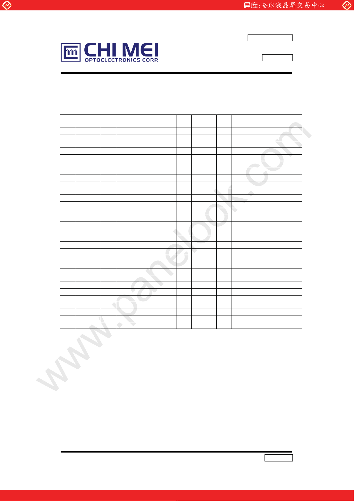
3.1 THE PIN ASSIGNMENT OF TTL INTERFACE CONNECTOR.
Pin
Symbol I/O Function Pin
No.
1 GND - Ground 31 GE1 I Green even data 1
2 RO0 I Red odd data 0 32 GE2 I Green even data 2
3 RO1 I Red odd data 1 33 GE3 I Green even data 3
4 RO2 I Red odd data 2 34 GE4 I Green even data 4
5 RO3 I Red odd data 3 35 GE5 I Green even data 5
6 RO4 I Red odd data 4 36 GND - Ground
7 RO5 I Red odd data 5 37 BE0 I Blue even data 0
8 GND - Ground 38 BE1 I Blue even data 1
9 GO0 I Green odd data 0 39 BE2 I Blue even data 2
10 GO1 I Green odd data 1 40 BE3 I Blue even data 3
11 GO2 I Green odd data 2 41 BE4 I Blue even data 4
12 GO3 I Green odd data 3 42 BE5 I Blue even data 5
13 GO4 I Green odd data 4 43 GND - Ground
14 GO5 I Green odd data 5 44 VSYN I Vertical sync.
15 GND - Ground 45 HSYN I Horizontal sync.
16 BO0 I Blue odd data 0 46 ENAB I Data enable signal
17 BO1 I Blue odd data 1 47 GND - Ground
18 BO2 I Blue odd data 2 48 GND - Ground
19 BO3 I Blue odd data 3 49 DCLK I Dot clock signal
20 BO4 I Blue odd data 4 50 GND - Ground
21 BO5 I Blue odd data 5 51 GND - Ground
22 GND - Ground 52 NC - Must be floating
23 RE0 I Red even data 0 53 NC - Must be floating
24 RE1 I Red even data 1 54 GND - Ground
25 RE2 I Red even data 2 55 GND - Ground
26 RE3 I Red even data 3 56 GND - Ground
27 RE4 I Red even data 4 57 VDD - +5V Power supply
28 RE5 I Red even data 5 58 VDD - +5V Power supply
29 GND - Ground 59 VDD - +5V Power supply
30 GE0 I Green even data 0 60 VDD - +5V Power supply
Connector Part No.: 52760-0600(Molex)
User’s connector Part No: 53475-0600(Molex)
www.panelook.com
Doc.No:14005207
Issue Date: MAY.15,2000
Model: M141X102
APPROVAL
Symbol I/O Function
No.
8/22
Version 2.0
One step solution for LCD / PDP / OLED panel application: Datasheet, inventory and accessory!
www.panelook.com
Page 9

Global LCD Panel Exchange Center
3.2 INPUT SIGNAL TIMING SPECIFICATIONS
www.panelook.com
Doc.No:14005207
Issue Date: MAY.15,2000
Model: M141X102
APPROVAL
The specifications of input signal timing are as the following table and timing diagram
Signal Parameter Symbol Min Typ Max Unit Remarks
DCLK
DATA
VSYNC
HSYNC
Note:
2. VSYNC and HSYNC are negative polarity in the spec.
3.DE (Data Enable) should be positive polarity in the spec.
4. HSYNC should appear during blanking period of frame cycle.
Pixel clock Frequency fck 25 32.5 40 MHz
Pixel clock period Tck 40 30 25 ns
Duty ratio (%Tch) - 40 50 60 % Tch/Tck
Rise time Trck - 7.9 - ns
Fall time Tfck - 7.3 - ns
Setup time Tsd 5.0 - - ns
Hold time Thd 6.0 - - ns
Rise time Trd - 8.9 - ns
Fall time Tfd - 8.2 - ns
Setup time Tsde 4 5.8 - ns DE
Hold time Thde 4.5 6.2 - ns
Vertical Frequency fv 50 60 75 Hz
Vertical period Tvp 769 806 1000 Thp
Vertical display blank period Tvdb 1 38 232 Thp
Vertical display active period
Vertical sync. back porch Vbp 0 29 199 Thp
Vertical sync. front porch Vfp 0 3 199 Thp
Vertical sync. pulse width Vpw 1 6 200 Thp
Horizontal period Thp 575 672 806 Tck
Horizontal display blank period
Horizontal display active period
Horizontal sync. back porch
Horizontal sync. front porch
Horizontal sync. pulse width Hpw 52 73 243 Tck
1.Data is latched at falling edge of DCLK in the spec. DCLK should appear during all
blanking period.
Tvda 768 768 768 Thp
Thdb 63 160 294 Tck
Thda 512 512 512 Tck
Hbp 52 53 281 Tck
Hfb 0 35 281 Tck
.
9/22
Version 2.0
One step solution for LCD / PDP / OLED panel application: Datasheet, inventory and accessory!
www.panelook.com
Page 10

Global LCD Panel Exchange Center
VSYNC
www.panelook.com
INPUT SIGNAL TIMING DIAGRAM
pw
V
Doc.No:14005207
Issue Date: MAY.15,2000
Model: M141X102
APPROVAL
HSYNC
DE
HSYNC
DE
DCLK
768
768
Vfp
fp
H
bp
V
vp
T
vda
vdb
T
1
pw
H
bp
H
hdb
T
T
2
hp
T
hda
T
DATA
DCLK
DATA
DE
Valid display data (1024 Tck)
Invalid Valid
Tck
rck
T
fck
T
Tch
T
sd
90%
10%
hd
T
90%
10%
Trd / Tfd
T
sde
hde
T
90%
10/22
Version 2.0
One step solution for LCD / PDP / OLED panel application: Datasheet, inventory and accessory!
www.panelook.com
Page 11

Global LCD Panel Exchange Center
3.3 COLOR DATA INPUT ASSIGNMENT
Color
Basic
Colors
Gray
Scale
Of
Red
Gray
Scale
Of
Green
Gray
Scale
Of
Blue
Odd
Even
Black
Red
Green
Blue
Cyan
Magenta
Yellow
White
Red(0) / Dark
Red(1)
Red(2)
:
:
Red(61)
Red(62)
Red(63)
Green(0) / Dark
Green(1)
Green(2)
:
:
Green(61)
Green(62)
Green(63)
Blue(0) / Dark
Blue(1)
Blue(2)
:
:
Blue(61)
Blue(62)
Blue(63)
www.panelook.com
Doc.No:14005207
Issue Date: MAY.15,2000
Model: M141X102
APPROVAL
Data Signal
Red Green Blue
RO5 RO4 RO3 RO2 RO1 RO0 GO5 GO4 GO3 GO2 GO1 GO0 BO5 BO4 BO3 BO2 BO1 BO0
RE5 RE4 RE3 RE2 RE1 RE0 GE5 GE4 GE3 GE2 GE1 GE0 BE5 BE4 BE3 BE2 BE1 BE0
0
0
0
0
0
0
0
0
0
1
1
1
0
0
0
0
0
1
1
1
0
0
0
:
:
1
1
1
0
0
0
:
:
0
0
0
0
0
0
:
:
0
0
0
0
0
0
0
1
1
1
1
1
1
0
0
0
0
0
0
:
:
:
:
1
1
1
1
1
1
0
0
0
0
0
0
:
:
:
:
0
0
0
0
0
0
0
0
0
0
0
0
:
:
:
:
0
0
0
0
0
0
0
1
1
0
0
0
0
0
0
1
1
1
1
1
1
0
0
0
0
0
1
:
:
:
:
1
0
1
1
1
1
0
0
0
0
0
0
:
:
:
:
0
0
0
0
0
0
0
0
0
0
0
0
:
:
:
:
0
0
0
0
0
0
0
0
0
0
1
1
0
0
0
1
0
0
1
1
1
1
1
0
0
1
0
0
0
:
:
:
:
1
0
0
0
1
0
0
0
0
0
0
0
:
:
:
:
1
0
1
0
1
0
0
0
0
0
0
0
:
:
:
:
0
0
0
0
0
0
0
0
1
1
1
0
0
0
1
1
1
0
0
0
1
1
1
1
1
1
0
0
0
0
0
0
0
0
0
:
:
:
:
:
:
0
0
0
0
0
0
0
0
0
0
0
0
0
0
0
0
0
0
:
:
1
1
1
0
0
0
:
:
0
0
0
:
:
:
:
1
1
1
1
1
1
0
0
0
0
0
0
:
:
:
:
0
0
0
0
0
0
0
0
0
0
0
0
1
1
0
0
1
1
0
0
1
1
1
1
0
0
0
0
0
0
:
:
:
:
0
0
0
0
0
0
0
0
1
0
0
1
:
:
:
:
1
0
1
0
1
1
0
0
0
0
0
0
:
:
:
:
0
0
0
0
0
0
0
0
0
0
0
0
0
0
0
0
0
0
0
0
1
1
1
1
1
1
1
1
1
1
1
1
1
1
1
1
1
1
0
0
0
0
0
0
1
1
1
1
1
1
0
0
0
0
0
0
0
0
0
0
0
0
0
0
0
0
0
0
:
:
:
:
:
:
:
:
:
:
:
:
0
0
0
0
0
0
0
0
0
0
0
0
0
0
0
0
0
0
0
0
0
0
0
0
:
:
0
0
0
0
0
0
:
:
1
1
1
0
0
0
0
0
0
0
0
0
0
0
0
:
:
:
:
:
:
:
:
:
:
0
0
0
0
0
0
0
0
0
0
0
0
0
0
0
0
0
0
0
0
1
0
0
0
0
0
1
0
0
0
:
:
:
:
:
:
:
:
:
:
1
1
1
1
1
1
1
1
1
1
0
0
1
1
1
11/22
Version 2.0
One step solution for LCD / PDP / OLED panel application: Datasheet, inventory and accessory!
www.panelook.com
Page 12

Global LCD Panel Exchange Center
Correspondence between Data and Display Position
S0001 S0002 S0003 S0004 S0005 S0006 S0007 S0008 S3071 S3072
C001 RE
GE
BE
www.panelook.com
RO
GO
BO
GE
Doc.No:14005207
Issue Date: MAY.15,2000
Model: M141X102
APPROVAL
GO
BO
0001
0001
0001
0002
0002
0002RE0003
0003
1024
1024
C768 RE
0001
GE
0001
BE
0001
RO
0002
GO
0002
BO
0002RE0003
GE
0003
GO
1024
BO
1024
3.4 POWER UP/DOWN SEQUENCE
10%
t4
10%
Vcc
0V
Signals
0V
10%
90%
90%
t1
t3
t2
t5
t6
CCFL
Timing Specifications:
0 ≤ t1 ≤ 10mS
0 ≤ t2 ≤ 50mS
0 ≤ t3 ≤ 50mS
t4 ≥ 1S
t5 ≥ 170mS
t6 ≥ 200mS (min.)
Notes: 1. Please avoid floating state of interface signal at invalid period.
2. When the interface signal is invalid, be sure to pull down the power supply for
LCD Vcc to 0V.
12/22
Version 2.0
One step solution for LCD / PDP / OLED panel application: Datasheet, inventory and accessory!
www.panelook.com
Page 13

Global LCD Panel Exchange Center
4. OPTICAL SPECIFICATIONS
The following optical specifications shall be measured in a dark room or equivalent state
(ambient luminance ≤1 lux, and at room temperature). The measurement must be taken after
backlight warming up for 20 minutes. The operation temperature is 25°C ± 2°C. The
measurement method is shown in Note 1.
Parameter Symbol Condition Min. Typ. Max. Unit Note
Contrast ratio CR Center 150 200 - - 1, 2
Horizontal
Viewing Angle
Ver tical
Average Luminance L
Brightness Uniformity Buni
Response Time
Chromaticity
Cross Talk CT
Rising Tr - 15 30 ms
Falling Tf
www.panelook.com
Doc.No:14005207
Issue Date: MAY.15,2000
Model: M141X102
APPROVAL
θx+
θy+
Center
CR ≥10
θx-
Center
CR ≥10
θy-
ave
IL = 6.0mA 150 180 - cd/m2 1, 4
θx = θy = 0
Center
θx = θy = 0
o
o
XW 0.300 0.320 0.340
YW 0.310 0.330 0.350
XR 0.570 0.590 0.600
Center
YR 0.310 0.330 0.350
XG 0.284 0.304 0.324
θx = θy = 0
o
YG 0.547 0.567 0.587
XB 0.140 0.160 0.180
Y
B
θx = θy = 0
o
50 60 50 60 30 40 -
degree 1, 3
50 60 -
1.0 1.2 1.4 1, 5
- 35 50 ms
0.100 0.120 0.140
- - 4.0 %
1, 6
1, 7
1, 8
Note 1: The method of optical measurement:
Viewing Field=2
º
Photodetector
(TOPCON BM-5A)
50 cm
TFT-LCD Module
13/22
Version 2.0
One step solution for LCD / PDP / OLED panel application: Datasheet, inventory and accessory!
www.panelook.com
Page 14

Global LCD Panel Exchange Center
Note 2: Definition of Contrast Ratio:
The contrast ratio can be calculated by the following expression:
Contrast ratio (CR) = L63 / L0
L63: Luminance on the white raster (gray level L63)
L 0: Luminance on the black raster (gray level L0)
CR = CR(5)
CR(x) is corresponding to the contrast ratio of a point x at figure Note 5.
Note 3: Definitions of Viewing Angle (CR ≥ 10):
www.panelook.com
Doc.No:14005207
Issue Date: MAY.15,2000
Model: M141X102
APPROVAL
Normal
θ
x = θy = 0º
θy- θy+
12 o’clock direction
y+
θ
y+
= 90º
x+
θX+ = 90º
Lave
x-
θx−
θx+
y-
L(1) + L(2) + L(3) + L(4) + L(5)
=
5
θX- = 90º
6 o’clock
y-
θ
= 90º
Note 4: Definition of Average Luminance:
The Luminance shall be measured with all pixels in the viewing field at white state (L63),
and the average luminance is defined in the following expression such as arithmetic mean
value of five spots across the LCD surface. The measuring points must be taken at the locations
shown in the following figure.
14/22
Version 2.0
One step solution for LCD / PDP / OLED panel application: Datasheet, inventory and accessory!
www.panelook.com
Page 15

Global LCD Panel Exchange Center
0 256 512 768 1023
0
Vertical Line Number
192
www.panelook.com
Horizontal Line Number
1
2
Doc.No:14005207
Issue Date: MAY.15,2000
Model: M141X102
APPROVAL
x
: Test point
384
576
767
Note 5: Definition of Brightness Uniformity (B
3
5
uni
4
):
Maximum luminance of 5 points
(Note 4).
Note 6: Definition of Response Time:
The response time is set initially by defining the “ Rising Time (Tr)” and the “ Falling Time
(Tf)” respectively. Tr and Tf are defined as following figure.
Buni=
Data input
Minimum luminance of 5 points
White L63 Black L0 White L63
Tr
100%
90%
10%
0%
15/22
Tf
Version 2.0
One step solution for LCD / PDP / OLED panel application: Datasheet, inventory and accessory!
www.panelook.com
Page 16

Global LCD Panel Exchange Center
A
)
A
(
)
(
)
Note 7: Definition of Chromaticity:
www.panelook.com
Doc.No:14005207
Issue Date: MAY.15,2000
Model: M141X102
APPROVAL
The color coordinates (X
, YW), (XR, YR), (XG, YG), and (XB, YB) are obtained with all pixels
W
in the viewing field at white, red, green, and blue states, respectively.
Note 8: Definition of Cross Talk (CT)
Y
(128, 384)
A,L
Y
(512, 672)
A, D
CT = | Y
Where:
– YA | / YA×100 (%)
B
Y
= Luminance of measured location without darkest gray pattern (Gray 0)
A
Y
= Luminance of measured location with darkest gray pattern (Gray 0)
B
(0, 0)
ctive
Gray 32
1023, 767
Y
(512, 96)
A, U
Y(896, 384
(256, 192)
Y
(128, 384)
B, L
Y
(512, 672)
B, D
0, 0
ctive
Gray 0
Gray 32
(1023, 767)
Y
(512, 96)
B,U
Y
(896, 384)
B,R
(768, 576)
16/22
Version 2.0
One step solution for LCD / PDP / OLED panel application: Datasheet, inventory and accessory!
www.panelook.com
Page 17

Global LCD Panel Exchange Center
5. Reliability Test Item
www.panelook.com
Doc.No:14005207
Issue Date: MAY.15,2000
Model: M141X102
APPROVAL
No. Test Item Conditions
High temperature
1.
storage test
Low temperature
2.
storage test
High temperature
3.
and high humidity
operation test
High temperature
4.
operation test
Low temperature
5.
operation test
Vibration test
6.
( operating )
Mechanical shock
7.
( non-operating )
Ta = 6 0
Ta = - 2 0
Ta = 4 0
( no condensation )
Ta = 5 5
Ta = - 5oC, 48h #1,#2,#3,#4,#5
o
C , 500h #1,#2,#3,#4,#5
o
C, 500h #1,#2,#3,#4,#5
o
C, 95%RH 500h
o
C, 500 h #1,#2,#3,#4,#5
10 ~ 500 Hz, 1 G, 20 min./cycle, X,Y,Z,
each 3 times
50 G, 11 ms, half sine wave, X,Y,Z,
each 1 times
Criterion
(Note)
#1,#2,#3,#4,#5
#3,#4,#5
#3,#4,#5
Note : The criterions are as following.
#1 : The Contrast Ratio criterion after this test item are ΔCR <= 20% or CR > minimal
specification.
ӔCR is the contrast ratio variation which is measured before and after this test item.
#2 : The module Power Supply Current ( Icc) <= Maximal Specification after this testing item.
#3 : The module is functional work after this test item.
#4 : The defect or mura are not increase after this test item.
#5 : The mechanical outline is no abnormal change , for example, inflation, distortion or metal
frame shift.
6. MECHNICAL DRAWING
Please refer to the attached drawings.
17/22
Version 2.0
One step solution for LCD / PDP / OLED panel application: Datasheet, inventory and accessory!
www.panelook.com
Page 18

Global LCD Panel Exchange Center
7. PRECAUTION
7. 1 ASSEMBLY AND HANDLING PRECAUTION
(1) Do not apply rough force such as bending or twisting to the module during assembly.
(2) To assembly and install module into user’s system are only in clean working areas. The
Dust and oil may cause an electrical short or worsen the polarizer.
(3) It’s not permitted to pressure or impulse the module because the LCD panel and backlight.
(4) Always follow the correct power sequence when user connects and operates the LCD
module to prevent damage to the CMOS LSI chips during latchup.
(5) Do not pull the I/F connectors in or out while the module is operation.
(6) Do not disassembly the module.
(7) Use a soft dry cloth without chemicals for cleaning, because the surface of polarizer is very
soft and easily scratched.
(8) Any moisture come into contact with the LCD module is dangerous because LCD modules
is turned on with moisture on its surface may cause it damage.
(9) The high temperature or humidity may reduce the performance of module, to store LCD
module within the specified storage condition.
(10) The ambient temperature is lower than 10ºC may reduce the display quality, for example,
response time become slowly, the starting voltage of CCFL is higher than room
temperature.
www.panelook.com
Doc.No:14005207
Issue Date: MAY.15,2000
Model: M141X102
APPROVAL
7.2 SAFTY PRECAUTION
(1) The startup voltage of backlight is approximately 1000 Volts. It may cause electrical shock
during assembly with inverter. Do not disassemble the module or insert anything into the
backlight unit.
(2) If the liquid crystal material leaks from the panel, it should be kept away from the eyes or
mouth. In case of contact with hands, skin or clothes, it has to be washed away thoroughly
with soap.
18/22
Version 2.0
One step solution for LCD / PDP / OLED panel application: Datasheet, inventory and accessory!
www.panelook.com
Page 19

Global LCD Panel Exchange Center
8. PACKAGING
8.1 PACKING SPECIFICATIONS
(1) 10 LCD modules / 1 Box
(2) Box dimensions : 443(L) X 433(W) X 388(H) mm
(3) Weight : approximately 14.5 Kg ( 10 modules per box)
8.1 PACKING Method
www.panelook.com
Doc.No:14005207
Issue Date: MAY.15,2000
Model: M141X102
APPROVAL
The Figure. 8-1,2 show the packing method.
Figure. 8-1 Packing method
Figure. 7-1 Packing method
19/22
Version 2.0
One step solution for LCD / PDP / OLED panel application: Datasheet, inventory and accessory!
www.panelook.com
Page 20

Global LCD Panel Exchange Center
www.panelook.com
Doc.No:14005207
Issue Date: MAY.15,2000
Model: M141X102
APPROVAL
Figure. 8-2 Packing method
20/22
Version 2.0
One step solution for LCD / PDP / OLED panel application: Datasheet, inventory and accessory!
www.panelook.com
Page 21

Global LCD Panel Exchange Center
9. INCOMING INSPECTION DAY
The Supplier should be acquainted the inspection results (acceptance or rejection) by
Customer, and the results are in accordance with the incoming inspection standard within 30
days after the date of the bills of lading.
Should Customer fail to so notify the Supplier within the said 30 days period. The
Customer’s right to reject the LCMS shall then lapse, and the said LCMS shall be deemed to
have been accepted by the customer.
www.panelook.com
Doc.No:14005207
Issue Date: MAY.15,2000
Model: M141X102
APPROVAL
21/22
Version 2.0
One step solution for LCD / PDP / OLED panel application: Datasheet, inventory and accessory!
www.panelook.com
Page 22

Global LCD Panel Exchange Center
10. Definition of Shipping Label on Module
The barcode nameplate is pasted on each module as illustration, and its
definitions are as following explanation.
www.panelook.com
Doc.No:14005207
Issue Date: MAY.15,2000
Model: M141X102
APPROVAL
M 1 4 1 X 1 0 1 Rev. C1
CHI MEI OPTOELECTRONICS
(1) Model Name : M141X101
(2) Revision : Rev.XX, for example : C1, C2 …etc.
(3) Serial ID : 0 1
Serial ID include the information as list.
1. Manufactured Date : Year : 0~9, for 2000~2009
2. Revision Code : cover all the change
3. Model code
4. Serial No. : Manufacturing sequence of product
5. Product Line : 1 -> Line1, 2 -> Line 2 …,etc.
0 1 C 1 0 0 1 0 3 9 1 0 0 0 1
C 1 0 0 1 0 3 9 1 0 0 0 1
Month : 0~9, A~C, for Jan. ~ Dec.
Day : 0~9, A~Y, for 1
MADE IN TAIWAN
st
to 31st, exclude I and O
Serial No.
Product Line
Year, Month, Date
CMO Internal Use
CMO Internal Use
Revision
Model Code
22/22
Version 2.0
One step solution for LCD / PDP / OLED panel application: Datasheet, inventory and accessory!
www.panelook.com
Page 23

Global LCD Panel Exchange Center
www.panelook.com
One step solution for LCD / PDP / OLED panel application: Datasheet, inventory and accessory!
www.panelook.com
Page 24

Global LCD Panel Exchange Center
www.panelook.com
E207943
Reating: 5Vdc 450mA
Model: M141X102
One step solution for LCD / PDP / OLED panel application: Datasheet, inventory and accessory!
www.panelook.com
 Loading...