

Page 1
SAFE X4 / X4.1
CM Manufactory GmbH
Otto-Hahn-Str. 3
D-72406 Bisingen
Tel. +49-(0)7476-9495-0
Fax. +49-(0)7476-9495-195
www.cm-manufactory.com
Zielgruppe/
Target audience
Zeichenerklärung/
Explanation of
signs
SAFE X4/X4.1
Original Bedienungsanleitung
Sicherheitsschaltgerät zur Kontaktvervielfachung in Not-Halt-Kreisen,
Schutztürüberwachungs-schaltungen
und anderen Sicherheitskreisen
Original operating instructions
expansion module
Einleitung
Diese Bedienungsanleitung soll Sie mit
den Erweiterungsmodulen SAFE X4 und
SAFE X4.1 vertraut machen.
Die Erweiterungsmodule sind verwendbar bis Kategorie 4 / PL e nach EN ISO
13849-1, je nach Basisgerät und Verdrahtung.
Die Bedienungsanleitung richtet sich an
folgende Personen:
Qualifizierte Fachkräfte, die Sicher-
heitseinrichtungen für Maschinen und
Anlagen planen und entwickeln und
mit den Vorschriften über Arbeitssicherheit und Unfallverhütung vertraut
sind.
Qualifizierte Fachkräfte, die Sicher-
heitseinrichtungen in Maschinen und
Anlagen einbauen und in Betrieb
nehmen.
In dieser Bedienungsanleitung werden einige Symbole verwendet, um wichtige Informationen hervorzuheben:
Dieses Symbol steht vor Textstellen, die
unbedingt zu beachten sind. Nichtbeachtung führt zur Verletzung von Personen
oder zu Sachbeschädigung
Dieses Symbol kennzeichnet Textstellen,
die wichtige Informationen enthalten.
Dieses Zeichen kennzeichnet auszuführende Tätigkeiten
Nach diesem Zeichen wird beschrieben,
wie sich der Zustand nach einer ausgeführten Tätigkeit ändert.
©
Copyright
gen, die dem technischen Fortschritt dienen, vorbehalten.
Alle Rechte vorbehalten. Änderun-
Introduction
This operating instruction should make
you familiar with the contact expansionmodul SAFE X4 and SAFE X4.1.
The extension modules use usable up
to Category 4 / PL e (EN ISO 13849-1)
depending an basis unit and wiring.
The operating instruction is addressed to
the following persons:
Qualified professionals who plan and
develop safety equipment for machines and plants and who are familiar with the safety instructions and
safety regulations.
Qualified professionals, who install
safety equipment into machines and
plants and put them into operation.
The operating instruction contains several symbols which are used to high-light
important information:
This symbol is placed in front of text
which has to be absolutely paid attention
to. Nonobservance leads to serious injuries or damage to property.
This symbol is placed in front of text,
which contains important information.
This sign is placed in front of activities
After this sign follows a description on
how the situation has changed after an
activity is performed.
©
Copyright
serve technical improvements are reserved.
All rights reserved. Changes, which
200803 1
Page 2
SAFE X4 / X4.1
Bestimmungsgemässe
Verwendung
Application:
Zu Ihrer Sicherheit
For your safety
Sicherheitshinweise
Das Erweiterungsmodul SAFE X4 (mit Querschlußsicherheit) / SAFE X4.1 (ohne Querschlußsicherheit) ist bestimmt für den Einsatz
als:
Nachschaltrelais zur Kontaktvervielfälti-
gung in Not-Aus-Einrichtungen, Schutztüren und Sicherheitsstromkreisen nach
DIN EN 60204 Teil1
(Ergänzende Informationen)
Personen - und Sachschutz sind nicht mehr
gewährleistet, wenn das Sicherheitsrelais
nicht entsprechend seiner bestimmungsgemäßen Verwendung eingesetzt wird.
Beachten Sie unbedingt die folgenden
Punkte:
Das Gerät darf nur unter Beachtung die-
ser Bedienungsanleitung von Fachpersonal installiert und in Betrieb genommen
werden, das mit den geltenden Vorschriften über Arbeitssicherheit und Unfallverhütung vertraut ist. Elektrische Arbeiten
dürfen nur von Elektrofachkräften durchgeführt werden.
Beachten Sie die jeweils gültigen Vor-
schriften, insbesondere hinsichtlich der
Schutzmaßnahmen.
Der Gefahrenbereich muß vom Montage-
platz des Starttasters einsehbar sein.
Der Start der Anlage muß aus dem Ge-
fahrenbereich heraus unmöglich sein
Reparaturen, insbesondere das Öffnen
des Gehäuses, dürfen nur vom Hersteller
oder einer von ihm beauftragten Person
vorgenommen werden. Ansonsten erlischt jegliche Gewährleistung.
Vermeiden Sie mechanische Erschütte-
rungen beim Transport oder im Betrieb;
Stöße größer 5g/33Hz können zur Beschädigung des Gerätes führen.
Montieren Sie das Gerät in einem staub-
und feuchtigkeitsgeschütztem Gehäuse;
Staub und Feuchtigkeit kann zu Funktionsstörungen führen.
Sorgen Sie für eine ausreichende
Schutzbeschaltung bei kapazitiven und
induktiven Lasten an den Ausgangskontakten.
Safety indications
The contact expansion module SAFE X4 (with
opposite polarity between channels) and
SAFE X4.1 (without opposite polarity between
channels) can be used for:
Contact expansion in emergency stop
and door protection circuits and Safety
circuits according to DIN EN 60204 Part1
(Additional information)
Person and object-protection are not guaranteed, if the safety relay is not used by its intended purpose.
Please do note the following points:
The unit should only be installed and op-
erated by persons, who are familiar with
both these instructions and the current
regulations for safety at work and accident prevention.
Follow local regulations as regards pre-
ventative measures.
The danger area must be observable by
the assembling place of the start button.
Starting the machine while standing in
the dangerous area must be impossible.
It is not allowed to reach the start bottom
out of the dangerous area.
Any guarantee is void following opening
of the housing or unauthorized modifications.
Avoid mechanical vibrations greater than
5 g / 33 Hz when transporting and in operation.
The unit should be panel mounted in an
enclosure rated at IP 54 or better, otherwise dampness or dust could lead to
function impairment.
Adequate fuse protection must be pro-
vided on all output contacts with capacitive and inductive loads.
200803 2
Page 3
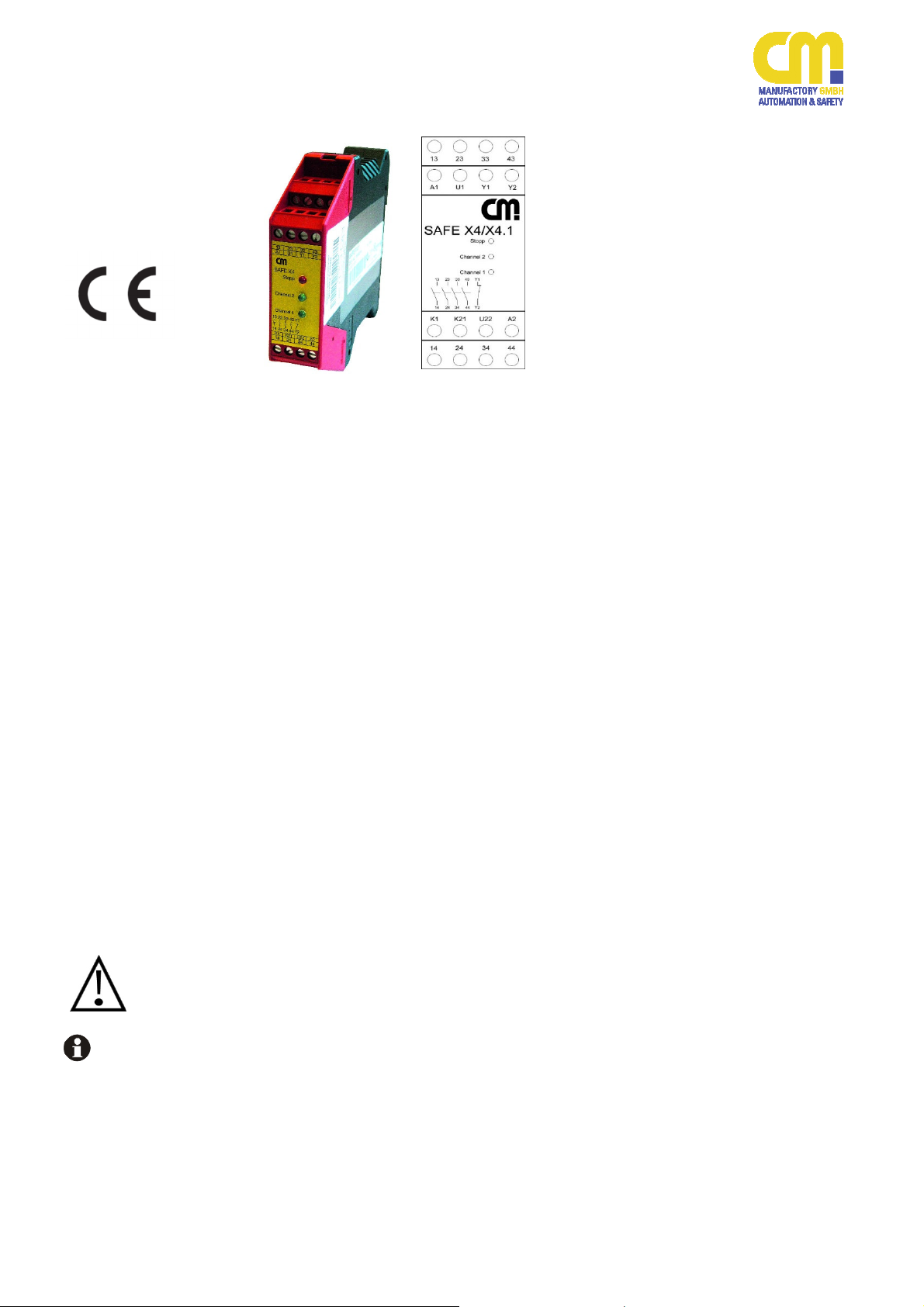
SAFE X4 / X4.1
13-14, 23-24, 33-34,
43-44
Y1-Y2
Aufbau und Funktionsweise
A1
A2 U1 U22 K1 K21 13 23 33 43
elektr. Sicherung
Transformator /
electr. Fuse
transformer
Überwachungslogik /
Controller Logic
K1
AC
DC
+
-
Ausgangskontakte:
Sicherheitsstrompfade (Schließer)
Rückführkreis
Das Erweiterungsmodul wird zur Kontaktvervielfachung eines Sicherheitsrelais eingesetzt.
An ein Sicherheitsrelais können mehrere Erweiterungsmodule angeschlossen werden.
Für das Betreiben des Gerätes muß eine
Hilfsspannung an die Klemmen A 1 und A 2
angelegt werden. An der Klemme U1 steht
dann eine Spannung von 24 V DC zur Verfügung. K21 und K1 werden nach den entsprechenden Anwendungsbeispielen beschalten.
Zum START des Gerätes muß der bzw. die
an K21 und K1 angeschossener / angeschlossene Sicherheitsstromkreis/-e geschlossen
werden.
Danach sind die Sicherheitskontakte des
SAFE 4 und SAFE 4.1 geschlossen.
Die LED´s ´channel 1´ (Kanal 1) und ´channel
2´ (Kanal 2 ) leuchten.
Der Rückführkreis muß an die entsprechenden Klemmen des Sicherheitsrelais oder in
Reihe zum Starttaster angeschlossen werden.
Die LED Stop leuchtet bei vorhandener Betriebsspannung, wenn einer oder beide Kanäle spannungsfrei sind
.
Assembly and function
(function circuit diagram)
K2
14 24 34 44
Output contact:
normally safety open
feed back circuit
The expansion module can be used to get
more safety contact and is used for contact
expansion together with a safety relay. Several expansion modules can be connected to
one safety relay.
An supply voltage must be applied at terminals A 1 and A 2. On terminal U1 24VDC is
available. K21, K1 have to be connected according to the application examples.
To activate the device the circuits for K21, K1
have to be closed.
Then the safety contacts of the SAFE X4 and
SAFE X4.1 are closed.
The „channel 1“ and „channel2“ LED illuminates.
The feed back circuit must be connected to
the according terminals off the Safety relay or
in series to the start.The LED „Stop“ will illuminate if the supply voltage is o.k. but there is
no voltage on one or both channels.
Y1
Y2
200803 3
Page 4

SAFE X4 / X4.1
Mechanische
Montage
mechanical
mounting
Elektrischer
Anschluß
Electronic
Connection
Montage und
Inbetriebnahme
Für eine sichere Funktion muß das Sicherheitsrelais in ein staub- und feuchtigkeits geschütztes Gehäuse eingebaut
werden (IP54).
Führen Sie die Verdrahtung entsprechend des Verwendungszweckes durch.
Orientieren Sie sich dabei an den Anwendungsbeispielen. Generell ist das Sicherheitsrelais nach folgenden Angaben
zu verdrahten:
1. Rückführungskreis schließen
Montieren Sie das
Sicherheitsrelais auf eine
Normschiene
Rückführkreis:
Y1 – Y2 muß an den Rückführkreis des Sicherheitsrelais angeschlossen werden.
Mounting and line up
The unit should be panel mounted in an
enclosure rated at IP 54 or better, otherwise dampness or dust could lead to
function impairment.
Carry out the wire appropriate the use.
Orientate yourself according to the examples of application.
General the safety-relay has to be wire
under following specifications:
1. Close the feedback control loop
There is a notch on the
rear of the unit for DIN-rail attachment.
feed back circuit: Y1 and Y2
have to be connected to the feed
back loop off the safety relay.
Start
13 23 33 43
A1 U1 Y1 Y2
riese
Safe X4/X4.1
13 23 33 43 Y1
Stop +
Channel
2 +
14 24 34 44 Y2
Channel
1 +
K1 K21 U22 A2
14 24 34 44
X1
X2
SAFE.. .
Anschlußklemmen für Rückführkeis
terminal for feed back circuit on the safety relay
Y1
Y2
S33
SAFE...
Rückfühkreis in Reihe zum Start Taster
Feed back circuit in serie to the start button
Y1
Y2
S34
200803 4
Page 5

SAFE X4 / X4.1
2. Aktivierungskreis schließen
Zum Starten des Gerätes muß der Sicherheitskontakt des Sicherheitsrelais
geschlossen sein.
SAFE X4.1: Ohne Querschlußsicherheit
Schließen sie die Kontakte des Sicherheitsrelais wie folgt an:
Kanal 1 (13-14) bzw. PNP-Ausgang 1
=> U1-K1 bzw. K1
Kanal 2 (23-24) bzw. PNP-Ausgang 2
U1-K21 bzw. K21
Bei einkanaligen Anwendungen entfällt die gestrichelte Verbindung. Die
Anschlußklemmen K21 und K1
werden gebrückt.
SAFE X4: Mit Querschlußsicherheit
Schließen sie die Kontakte des Sicherheitsrelais wie folgt an.
Kanal 1 (13-14) => U1-K1
Kanal 2 (23-24) => U22-K21
Bei einkanaligen Anwendungen wird
U1-K1 und U22-K21 gebrückt. Der
Kontakt des Sicherheitselementes
wird in Reihe zur Spannungsversorgung an die Klemme A1 angeschlossen.
13
23
14
24
U1
+24VDC
ohne Querschlußsicherheit / without opposite polarity
Die Verdrahtung der Versorgungsspannung ist abhängig vom Gerätetyp (s. Typenschild am Gerät).
K21
K1
2. Close the activation circuit
To start the SAFE X4 or SAFE X4.1 the
safety circuits of the safety relay must be
closed.
SAFE X4.1: without opposite polarity
Connect the safety contacts of the
safety relay to the expansion module
according to the wiring diagram:
Channel 1 (13-14) / PNP-Output
=> U1-K1 / K1
Channel 2 (23-24) / PNP-Output
U21-K21 / K21
When using an single channel application do not connect the dotted connection. In case off this make a
bridge between the terminal K21 an
K1.
SAFE X4: with opposite polarity
Connect the safety contacts of the
safety relay to the expansion module
according to the wiring diagram.
Channel 1 (13-14) => U1-K1
Channel 2 (23-24)=> U22-K21
When using a single channel application bridge U1-K1 and U22-K21.
Connect the tripping element in series to the supply voltage to the terminal A1.
13
14
23
24
U1
+24VDC
mit Querschlußsicherheit / with opposite polarity
The wire of the supply voltage is dependent
on device-model (see type plate on the device).
K1
K21
U22
0V
200803 5
Page 6

SAFE X4 / X4.1
3. Versorgungsspannung
Beachten Sie unbedingt die maximalen
Leitungslängen.
Schließen Sie die Versorgungsspannung an die Klemmen A1
und A2 an. z.B. bei 24 V DC:
A1= UV+ / A2= UV-
Bei der 24VAC/DC Variante ist
folgendes zu beachten:
Bei 24VDC ist A1 an +24VDC und
A2 an 0V anzuschließen.
Verbinden Sie die Klemme U22
mit Erde (nicht bei 24 VAC/DCGerät). Die Verbindung muß lösbar sein.
Wartung und Reparatur
Das Sicherheitsrelais arbeitet wartungsfrei.
Zum Austausch des Gerätes empfehlen
wir die Kabel 1 zu 1 abzuschrauben und
an das Austauschgerät anzuschrauben.
3. Supply voltage
Please note the max. lengths of the cables.
The Supply voltage has to be
connected to the terminals A1
and A2.
When using the 24VAC/DC variant following must be considered:
When using 24VDC then A1 must be
connected to +24VDC and A2 to 0V.
Connect the clamp U22 with
earth (not allowed by version
24VAC/DC). The connection has
to be soluble.
Maintenance and repair
The safety-relay works maintenance-free.
For exchange of the device, we advisable
the terminals 1 to 1 screw of and screw
on the exchange-device.
1. Kabel abschrauben und an das
Austauschgerät anschrauben.
2. Nehmen Sie das defekte Gerät
von der Normschiene.
3. Montieren Sie das neue Gerät
auf die Normschiene.
1. You must screw off the cable
and screw on the exchange device.
2. Take away the defective device
from the DIN-Rail.
3. Mount the new device on the
DIN-Rail.
200803 6
Page 7

SAFE X4 / X4.1
Erdschluß bei
AC-Variante (Trafo) /
Earth fault AC-version
(with transformer)
Erdschluß bei
AC/DC-Variante /
Earth fault DC-version
(with electronic fuse
protection)
Fehlfunktion der Kontakte /
Faulty contact
Functions
Nur eine LED Leuchtet /
Only one or no
LED illuminates
Fehler/Störungen, Auswirkung
und Maßnahmen
Die Versorgungsspannung bricht zusammen und die Sicherheitskontakte werden
geöffnet.
Die Sicherung löst aus und die Sicherheitskontakte werden geöffnet. Nach
Wegfall der Störursache und Einhalten
der Betriebsspannung ist das Gerät wieder betriebsbereit.
Bei verschweißten Kontakten ist nach
dem Öffnen keine neue Aktivierung möglich.
Externer Beschaltungsfehler oder interner Fehler liegt vor
Faults, effect and measures
The power supply breaks down and the
safety contacts off the expansion module
opens.
An electronic fuse release the output
contacts to open. Once the reason of the
disturbance is removed and the rated
voltage is observed, the device is ready
for operation.
In the case of welded contacts, further
activation is not possible following an
opening of the input circuit.
External wiring fault or internal fault is
present. Test the external wiring.
When the flaw is still available, send the
device to CM Manufactory GmbH.
200803 7
Page 8

SAFE X4 / X4.1
Elektrische Daten / electrical data
Leitungsdaten / conductor data
Kontaktdaten / contact data
clearance
Mechanische Daten / mechanical data
Umgebungsdaten / environmental data
Zertifizierungen / certifications
Technische Daten / Technical Data
Versorgungsspannung UV / supply voltage UV 48, 110-127, 230V AC (galv. Trennung / Trafo) / (with galvanic dis-
connection / transformer)
24V AC/DC (elektronische Sicherung) /(electronic fuse protection)
Spannungsbereich / voltage range 0,85 ...1,1 UV
Frequenz (AC-Variante) / frequency (AC-type) 50 ... 60 Hz
Leistungsaufnahme ca. / power consumption appr. 4 VA
Leiteranschluß / conductor connection 1 x 2,5 mm2 Massivdraht (Cu) / massive wire
2 x 1,5 mm2 Litze (Cu) mit Hülse / strand with hull
UL: Use 60/75°C copper wire only!
UL:Max. Leitungslängen (Eingangskreis) /
max. conductor length (input circuit)
Leiterquerschnitt / conductor cross-section 2 x 1,5 mm2
Temperatur / temperature + 25°C
Kontaktbestückung / contact-allocation 4 Schließer / 4 normally safety open
Kontaktart / contact type Relais zwangsgeführt / relay positive guided
Kontaktmaterial / contact material Ag SnO2 / Ag SnO2
Schaltspannung / switching voltage 250V AC, 24V DC
Schaltstrom max / min / switching current max / min 6 A AC/DC / 10mA
Summenstrom max. / max. sum of switching current 16 A
Schaltleistung max. / max. switching capacity 1500 VA (ohmsche Last) / 1500 VA (ohms load)
Gebrauchskategorie / Contact ratings AC15: 5A
Mechanische Lebensdauer / mechanical lifetime 107 Schaltspiele / switches
Elektrische Lebensdauer / electrical lifetime 105 Schaltspiele / switches (3,5A, 250VAC)
Kriech- und Luftstrecken / creeping distance and
Kontaktabsicherung / contact security 10 A flink /10 A brisk
Kurzschlussfestigkeit / Short Circuit Withstand
entsp. / acc IEC60947-5-1
Weld Free Protection at IPSCC≥1kA SCPD*) (Vorsicherung / Fuse links), Gebrauchskategorie / size D01
gL/gG nach / acc IEC IEC60269-1; IEC60269-3-1;
VDE036-T301
*) Short Circuit Protection Device
Spannung an U1 / voltage on U1 24V DC
Gehäusematerial / housing material Polyamid PA 6.6
Abmessungen (BxHxT) in mm / dimensions ( bxhxd ) 22,5 x 114,5 x 99
Befestigung / fastening Schnappbefestigung für Normschiene / click-fastening for DIN-Rail
Luftfeuchtigkeit Wechselklima 95% 0-50°C
Anzugsmoment für Anschlussklemmen / Torque setting for connection terminals
150m
1 Öffner / 1 normally closed contact
(Rückführkreis / feedback circuit)
DC13: 6A
- für Verschmutzungsgrad 2,
Überspannungs-Kategorie 3/ 250 V
at pollution grade 2,
over voltage category 3/ 250 V
- Basisisolierung: Überspannungskategorie3/250V
basis isolation: over voltage category 3/250V
Schließer / NO-contacts: 10A
Öffner / NC-contacts: 6A
min. 0,5 Nm / max. 0,6 Nm
(UL: „Tighten to 0.5-0.6 N.m. Overtorquing may cause enclosure breakage“)
Umgebungstemperatur / operating temperature -25°C ... +55°C ( UL:…+40°C)
Schutzart Klemmen / terminal type IP 20
Schutzart Gehäuse / housing type IP 40
Stoßfestigkeit / shock resistance 5g, 33 Hz VDE 0160
Geprüft nach / tested in accordance with EN ISO 13849-1
Erreichtes Level/Kategorie / achieved level/catgory Performance Level e, Kat./Cat: 4
MTTFD [Jahre] / MTTFD [years]
DC 99% “hoch/high”
CCF erfüllt/achieved
PFHD [1/h]
1,33*10
200803 8
185 “hoch/high”
-8
Page 9

SAFE X4 / X4.1
K21
K21
U1
13
14
K21
13
14
13
14
K1
23
24
Sicherheitskontakt
Sicherheitsrelais
Safety contact
safety relay
K1
23
24
Sicherheitskontakt
Sicherheitsrelais
safety contacts
safety relay
K1
U22
K1
K21
Sicherheitskontakt
Sicherheitsrelais
Safety contact
safety relay
U1
+24VDC
U1
+24VDC
U22
U1
+24VDC
0V
L(+)
13
14
A1
Anwendungsbeispiele
Die Erweiterungsmodule sind
verwendbar bis Kategorie 4 / PL
e nach EN ISO 13849-1, je nach
Basisgerät und Verdrahtung.
Beispiel 1: Einkanalige Kontakterweiterung ohne Querschlußsicherheitsüberwachung. (SAFE X4.1)
Nach Schließen des Sicherheitskontaktes vom Sicherheitsrelais
werden die Sicherheitskontakte
des SAFE X4.1 geschlossen.
Beispiel 2: Zweikanalige Kontakterweiterung ohne Querschlußsicherheitsüberwachung. (SAFE X4.1)
Nach Anlegen der Versorgungsspannung und Schließen der Sicherheitskontakte sind die Ausgangskontakte des Erweiterungsmodul geschlossen.
Beispiel 3: Zweikanalige Kontakerweiterung mit Querschlußsicherheitsüberwachung. (SAFE X4)
Nach Schließen der Kontakte
13-14, 23-24 wird das SAFE X4
aktiviert.
Beispiel 4: Einkanalige Kontakerweiterung. (SAFE X4)
Nach Schließen der Kontakte
13-14 wird das SAFE X4 aktiviert.
Examples for applications
The extension modules use usable up to Category 4 / PL e (EN
ISO 13849-1) depending an basis unit and wiring.
Example 1: Single-channel
contact expansion without opposite polarity between the
channels. (SAFE X4.1)
After closing the safety contacts
of the safety relais the contacts
from the SAFE X4.1 close.
Example 2: Dual-channel contact expansion without opposite polarity between the
channels. (SAFE X4.1)
Connecting the power supply
and closing the contacts 13-14,
23-24 activates the expansion
module. After opening the contacts the safety contacts will
open.
Example 3: Dual-channel contact expansion with opposite
polarity between the channels.
(SAFE X4)
Closing the contacts 13-14, 2324 leads to the activation of the
expansion module.
Example 4: Single-channel
contact expansion. (SAFE X4)
Closing the contacts 13-14
leads to the activation of the expansion module.
200803 9
Page 10

SAFE X4 / X4.1
Gerätevarianten / Devices
Name / Name: Spannung / Voltage: Artikel-Nummer. / Article number:
SAFE X4 24 V AC / DC 45019
SAFE X4.1 24 V AC / DC 45021
SAFE X4 48 V AC 45195
SAFE X4.1 48 V AC 45196
SAFE X4 110-127 V AC 45197
SAFE X4.1 110-127 V AC 45200
SAFE X4 230 V AC 45201
SAFE X4.1 230 V AC 45203
200803 10
 Loading...