

Page 1
SAFE T
CM Manufactory GmbH
Otto-Hahn-Str. 3
D-72406 Bisingen
Tel. +49-(0)7476-9495-0
Fax. +49-(0)7476-9495-195
www.cm-manufactory.com
Zielgruppe/
Target audience
Zeichenerklärung/
Explanation of
signs
200803
Einleitung
Diese Bedienungsanleitung soll Sie mit
den Not-Halt-Sicherheitsrelais SAFE T
vertraut machen.
Die Bedienungsanleitung richtet sich an
folgende Personen:
Qualifizierte Fachkräfte, die Sicher-
heitseinrichtungen für Maschinen und
Anlagen planen und entwickeln und
mit den Vorschriften über Arbeitssicherheit und Unfallverhütung vertraut
sind.
Qualifizierte Fachkräfte, die Sicher-
heitseinrichtungen in Maschinen und
Anlagen einbauen und in Betrieb
nehmen.
In dieser Bedienungsanleitung werden einige Symbole verwendet, um wichtige Informationen hervorzuheben:
Dieses Symbol steht vor Textstellen, die
unbedingt zu beachten sind. Nichtbeachtung führt zur Verletzung von Personen
oder zu Sachbeschädigung.
Dieses Symbol kennzeichnet Textstellen,
die wichtige Informationen enthalten.
1
Dieses Zeichen kennzeichnet auszuführende Tätigkeiten.
Nach diesem Zeichen wird beschrieben,
wie sich der Zustand nach einer ausgeführten Tätigkeit ändert.
©
Copyright
gen, die dem technischen Fortschritt dienen, vorbehalten.
Alle Rechte vorbehalten. Änderun-
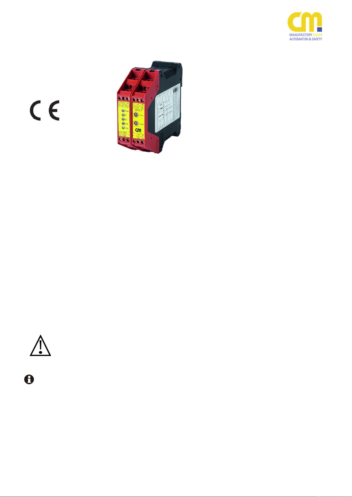
SAFE T
Original Bedienungsanleitung
Sicherheitsschaltgerät für Not-Haltund Schutztürapplikationen mit
Schaltverzögerung
Original operating instructions
Safety controller for e-stop and gate
monitoring applications with time-delayed contacts
Introduction
This operating instruction should
familiarize you with the emergency stop
device SAFE T.
The operating instruction is addressed to
the following persons:
Skilled personnel who plan or
develop safety equipment for machines and plants and are familiar
with the safety instructions and
safety regulations.
Skilled personnel who build in safety
equipment into machines and plants
and activate them.
The operating instruction contains several symbols which are used to high-light
important information:
This symbol shows text passages which
should absolutely payed attention too.
Non-observance leads to serious injuries
or damage to property.
This symbol shows passages which contain important information.
This sign is placed for activities.
This sign shows a description how the
condition has changed after an activity
has been carried out.
©
Copyright
serve technical improvements are reserved.
All rights reserved. Changes, which
Page 2
SAFE T
Bestimmungsgemäße
Verwendung
Intended application
Zu Ihrer Sicherheit
For your safety
Sicherheitshinweise
Das Not-Halt Sicherheitsrelais SAFE T ist
bestimmt für den Einsatz in:
Ein- oder zweikanalige Schaltungstechnik
für Not-Halt-Schalter
Zwei-kanalige Schaltungstechnik mit
Grenztaster für Schiebeschutzgitter
Verriegelungseinrichtung mit Zuhaltung
Gesteuertes Stillsetzen z.B. Abbremsen
eines Motores durch einen Frequenzumrichter
SAFE T hat zwei zeitverzögerte Kontakte.
Personen - und Sachschutz sind nicht mehr
gewährleistet, wenn das Not-Halt-Relais nicht
entsprechend seiner bestimmungsgemäßen
Verwendung eingesetzt wird.
Beachten Sie unbedingt die folgenden
Punkte:
Das Gerät darf nur unter Beachtung die-
Beachten Sie die jeweils gültigen Vor-
Reparaturen, insbesondere das Öffnen
Vermeiden Sie mechanische Erschütte-
Montieren Sie das Gerät in einem staub-
Sorgen Sie für eine ausreichende
Der Starttaster ist so anzubringen, dass
In regelmäßigen Zeitabständen sollte das
Diese Zeitverzögerten Kontakte können im Bereich von 0,05s – 600s eingestellt werden
ser Bedienungsanleitung von Fachpersonal installiert und in Betrieb genommen
werden, das mit den geltenden Vorschriften über Arbeitssicherheit und Unfallverhütung vertraut ist. Elektrische Arbeiten
dürfen nur von Elektrofachkräften durchgeführt werden.
schriften, insbesondere hinsichtlich der
Schutzmaßnahmen.
des Gehäuses, dürfen nur vom Hersteller
oder einer von ihm beauftragten Person
vorgenommen werden. Ansonsten erlischt jegliche Gewährleistung.
rungen größer als 10g (16ms) beim
Transport oder 4 g (10-200 Hz) im Betrieb.
und feuchtigkeitsgeschütztem Gehäuse;
Staub oder Feuchtigkeit kann zu Funktionsstörungen führen.
Schutzbeschaltung bei kapazitiven und
induktiven Lasten an den Ausgangskontakten.
man beim Start den Gefahrenbereich einsehen kann.
Not-Halt Relais ausgelöst werden und auf
richtige Funktion geprüft werden (mindestens jedes halb Jahr oder im Wartungszyklus der Anlage).
Safety indications
The safety relay SAFE T is intended for
the use with:
Single- or dual channel capability
emergency stop
Dual channel capability with limit
switches for safety gates
Safety gate with retaining device
Controlled shutdown, e.g. slow down a
motor with a frequency changer
SAFE T has two time-delayed contacts
Operator and object protection isn´t guaranteed, if the safety relay isn´t be used by the
defined application.
Please pay attention to the following
points:
The device may only be build in and op-
Pay attention to valid regulations, particu-
Any repairs have to be done by the man-
Avoid mechanical vibrations more than
The unit should be panel mounted in an
Adequate fuse protection must be pro-
The start button must installed at a posi-
The emergency stop relay should be test
This two contacts can be adjusted in
a time range from 0,05s up to 600s
erated by specialized staff, who are familiar with this instruction and the current
regulations for safety at work and accident prevention. Working on electrical
equipment is only allowed for
specialized staff.
larly in reference to preventative
measures.
ufacturer or a person which is authorized
by the manufacturer. It is prohibited to
open the device or implement unauthorized changes, otherwise any warranty expires.
10g (16ms) during the carriage and more
than 4g (10-200 Hz) during operation.
enclosure rated at IP 54 or better, otherwise dampness or dust could lead to
function impairment.
vided on all output contacts with capacitive and inductive loads.
tion from where the dangerous area
could be seen and observed.
in a defined time period (each half year or
after each check of the plant).
200803
2
Page 3
SAFE T
A1
A1 , A2
S33, S34, S35
S11,S12, S21, S22
13-14, 23-24
31-32
47-48, 57-58
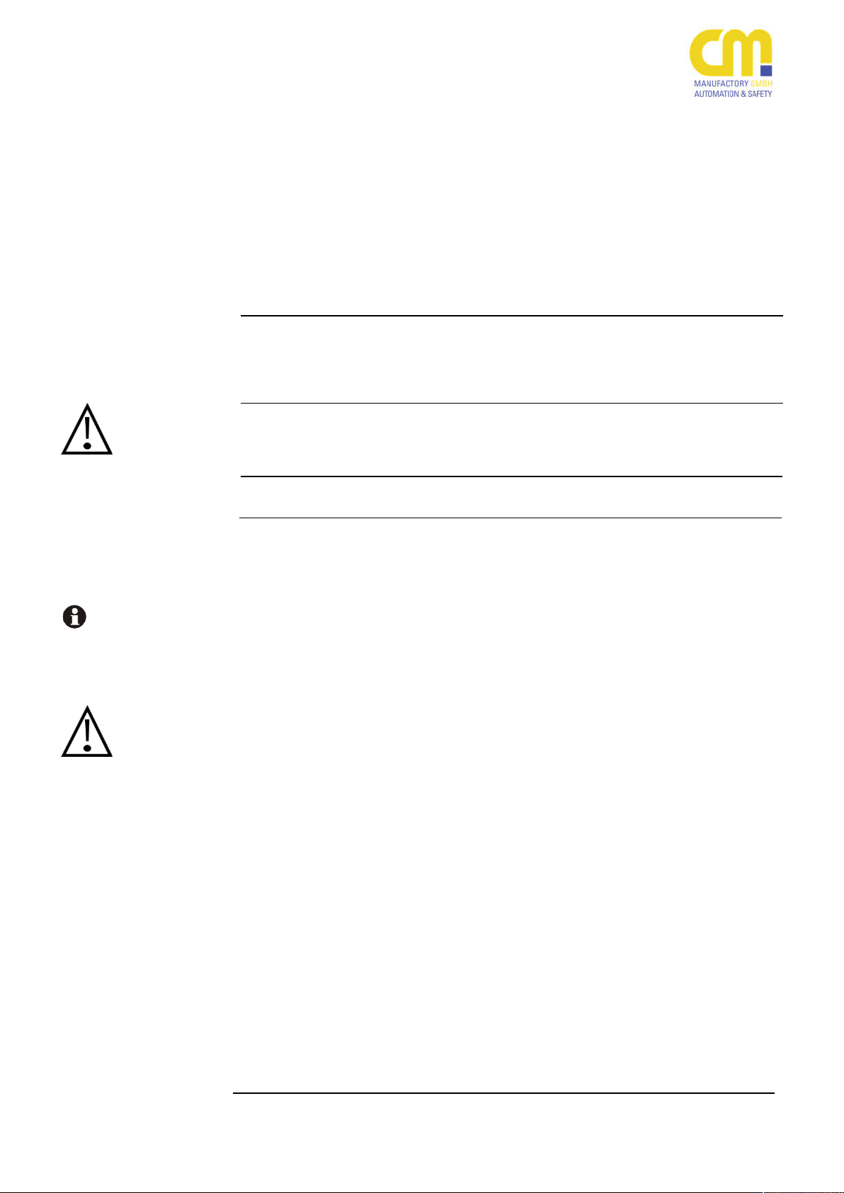
Aufbau und Funktionsweise
S21 S22
S11
Power
K1
K2
K3(t)
K4(t)
S33
S10
S35 S34
S12
31
32
47 48
57 58
TIME 1
TIME 2
13 14
23 24
A2
Anschluss Betriebsspannung
Start
Eingangsstromkreise
Sicherheitsstrompfade unverzögert
Öffner Kontakt
Sicherheitsstrompfade verzögert
Die Aktivierungs- und Eingangskontakte S33,
S34, S35, S11, S12, S21, S22 sind entsprechend des Verwendungszweckes zu verdrahten (s. „Anwendungsbeispiele“ und „Montage
und Inbetriebnahme“). Nach Anlegen der Versorgungsspannung an die Klemmen A1 /A2
leuchtet die LED „Power“. An der Klemme
S11 und S21 steht dann eine Spannung von
24 V AC/DC zur Verfügung die sich selbst auf
Querschluß überwacht. S12 und S21 werden
nach den entsprechenden Anwendungsbeispielen beschaltet.
Bei Start mit Überwachung der Starttaste
muss ein Schließerkontakt an die Klemmen
S33-S34 angeschlossen werden. Erst nach
Loslassen der Starttaste wird das SAFE T aktiviert.
Bei automatischem Start muss eine Brücke
an die Klemmen S34 und S35 angeschlossen
werden. Nach Schließen der Schütztür wird
das SAFE T automatisch gestartet.
Danach sind die Kontakte 13-14, 23-24, 47-48
und 57-58 geschlossen. Die LED´s K1, K2,
K3(t) und K4(t) leuchten.
Wird der Eingangskreis geöffnet, öffnen die
Sicherheitskontakte 13-14 und 23-24. Die
LED´s K1 und K2 erlöschen. Nach Zeitablauf
öffnen die Sicherheitskontakte 47-48 und 5758, die LED’s K3(t) und K4(t) erlöschen.
Das Gerät wird wieder aktiviert, wenn die Eingangskreise schließen, die Zeitverzögerten
Kontakte abgefallen sind und der Start-Taster
(wenn vorhanden) betätigt wird. Die LEDs K1,
K2, K3(t) und K4(t) leuchten wieder.
Die Zeit kann nur im spannungslosen Zustand
verändert werden.
A1 S35 S10 S11 S12 13 23 31 47 57
Logic
~
Power
~
t = 0,05s...600s
Assembly and function
(function circuit diagram)
K1
K2
K3
K4
Connection operation-voltage
activation contacts ( start key )
input contacts
immediate switching safety outputs
normally closed contact
time delayed safety outputs
The activation and input contacts S33, S34,
S35, S11, S12, S21, S22 are to be wired according the needs (see „applications“ and
„mounting and opening“). After the supply
voltage is applied to terminals A 1 and A 2,
the power LED illuminates. Contacts S11 and
S21 provide 24 V AC/DC and are monitored
for cross connection. S11 and S21 are to be
used according the application drawings.
For starting with monitoring the start key, a
normally open contact is to be connected to
S33 and S34. SAFE T will become active
again after releasing the start key.
For auto-start contacts S34 and S35 must be
bridged. After closing the safety door SAFE T
gets active and contacts between 13-14, 2324, 47–48 and 57-58 are closed.
LED’s K1, K2, K3(t) and K4(t) will be illuminated.
If input contacts open, then the safety outputs
13–14 and 23–24 are also opened immediately,also the LED’s K1 and K2 go off. After
the delay time the safety outputs 47-48 and
57-58 are opened and the LED’s K3(t) and
K4(t) go off.
SAFE T will come active again if the input
contacts are closed, the time delay contacts
are released and ( if installed ) the start key is
activated. LED’s K1, K2, K3(t) and K4(t) will
be illuminated again.
The time could only be change when the
power supply is off (voltage free).
5848322414S22S21S34S33A2
200803
3
Page 4
SAFE T
Mechanische
Montage
Mechanical
mounting
Elektrischer
Anschluss
Electronic
connection
S21 S22 A2 31 47 48
A1 S 11 S1 2 32 57 58
riese
Time
Safe T
+
Powe
+
K1
+
K2
+
K3(t
+
K4(t
Time
S10 S33 13 14
S35 S34 23 24
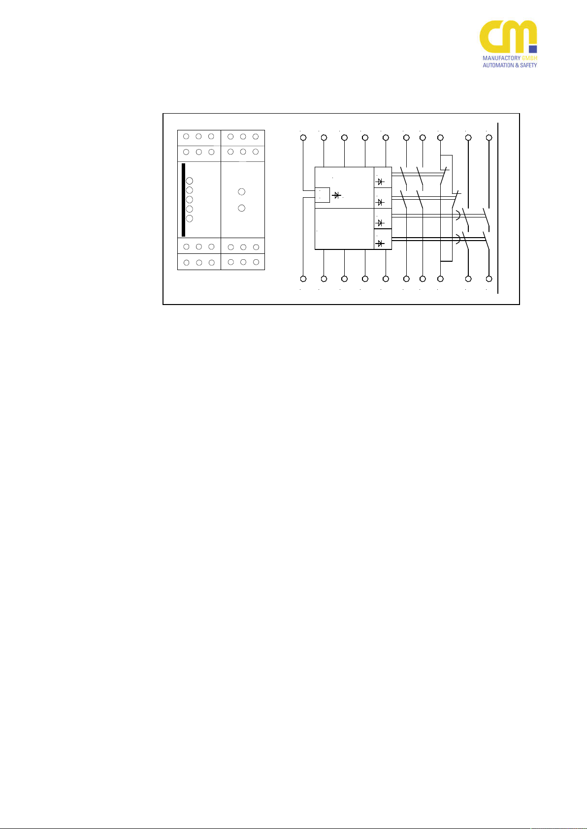
Montage und Inbetriebnahme
Für eine sichere Funktion muss das NotHalt-Sicherheitsrelais in ein staub- und
feuchtigkeitsgeschütztes Gehäuse IP54
eingebaut werden.
Führen Sie die Verdrahtung entsprechend des Verwendungszweckes durch.
Orientieren Sie sich dabei an den Anwendungsbeispielen. Generell ist das Sicherheitsrelais nach folgenden Angaben
zu verdrahten:
1. Aktivierungs- und Rückführungskreis
schließen
S34
automatische Aktivierung
automatic activation
Montieren Sie das Not-Halt-Sicherheitsrelais auf eine Normschiene
Automatische Aktivierung: Brücke zwischen S34 und S35 anschließen.
Überwachter Starttaster: Schließen Sie einen Starttaster zwischen den Klemmen S33 und
S34 an.
Überwachter Start mit Kontakterweiterung: Schließen Sie einen
Starttaster und die Öffnerkontakte der Erweiterungsschütze in
Reihe an die Klemmen S33 und
S34 an.
Start
S35
S33
S34
Start über Start-Taste
Start with Start bottom
Mounting and operating
The unit should be panel mounted in an
enclosure rated at IP 54 or better, otherwise dampness or dust could lead to malfunction.
Carry out the wire appropriate the use.
According to the examples of application.
Generally the safety-relay has to be
wired under following specifications:
1. Close the feedback control loop and
There is a notch on the rear of
the unit for DIN-Rail attachment.
the activation circuit
Automatic activation: Bridge S34
and S35.
Start monitoring: Connect a start
button between S33 and S34.
Start monitoring with contact
expansion: Connect a start button and the normally closed contacts of the contact expansion
between S33 and S34.
Start
K2 ext
K1 ext
S34
S33
Start über Start-Taste und
Anschluss einer Kontakterweiterung
Start with start bottom and contact expansion
200803
4
Page 5
SAFE T
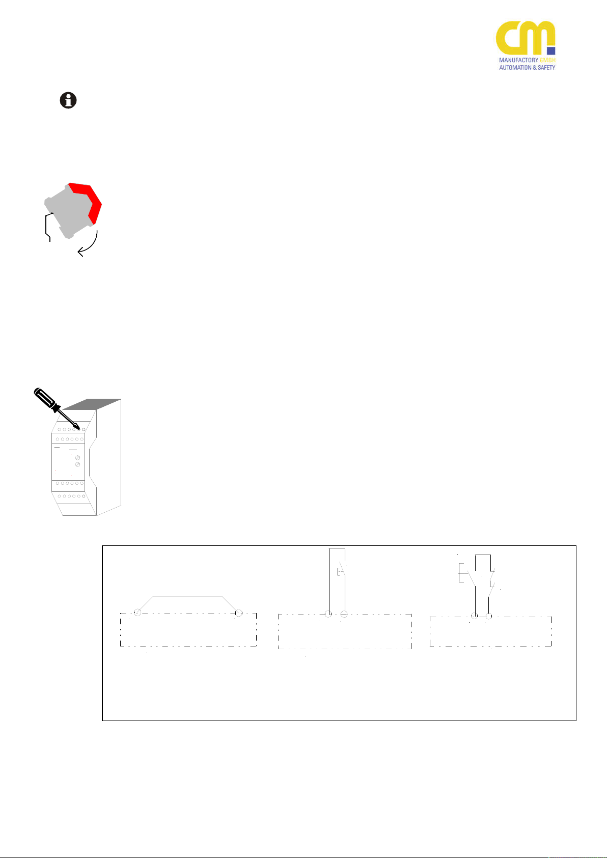
2. Eingangskreis schließen
Zweikanalig mit Querschlusssicherheit: Schließen sie die Öffnerkontakte des Auslöseelementes an S11- S12 und S21-S22 an
Einkanalig: Schließen sie den
Öffnerkontakte des Auslöseelementes an S11- S12 an. Brücken
Sie S21-S22 und S11-S10.
Kategorie 4 nur bei Verwendung
von zwangstrennenden Schaltern
und Verlegung der Kabel in getrennten Mantelleitungen.
Stop
S11 S12
S22
S21
zweikanalige Not-Halt-Schaltung
two channel emergency stop
3. Versorgungsspannung 24V AC/DC
Beachten Sie unbedingt die maximalen
Leitungslängen.
An die Klemme S11 und S21 darf kein
zusätzlicher Verbraucher angeschlossen
werden
Schließen Sie die Versorgungsspannung 24VDC an die Klemmen A1(+) und A2(-) an, die Versorgungsspannung 24VAC an
A1 und A2.
2. Close input circuit
Dual-channel connection: connect the normally closed contact
of the periphery module (e.g.
emergency stop, safety door
monitoring...) to S11-S12 and
S21-S22.
Single-channel connection: connect the normally closed contact
of the periphery module (e.g.
emergency stop, safety door
monitoring...) to S11-S12. Make
a bridge between S21-S22 and
S10-S11.
You have safety category 4, when using restricted
guided switches and lead the
wiring in separate coated cables.
Stop
S11S10 S12
S22
S21
einkanalige Not-Halt-Schaltung
one channel emergency stop
3. Supply voltage 24V AC/DC
Connect the supply voltage
24VDC to the terminals A1(+)
and A2(-), and the supply voltage
24VAC to the terminals A1 and
A2.
Please note the max. lengths of the cables.
At the terminal S11 and S21 it’s not allowed to add additional load.
200803
5
Page 6

SAFE T
Blinkende Anzeigen
Flashing indicators
Nach dem Abschalten
der zeitverzögerten
Kontakte ist kein Neustart möglich
After the switch off the
time delay contacts a
restart is not possible
Die Power LED leuchtet
nicht
Power LED does not
light
Das Gerät hat während
des Betriebes abgeschaltet oder läßt sich
nicht einschalten
The device had
switched off during it
has worked and it
could not be restarted
Wartung und Reparatur
Das Sicherheitsrelais arbeitet
wartungsfrei.
Zum schnellen Austausch des Gerätes
sind die Klemmen abnehmbar.
vom Gerät (1)
von der Normschiene (2)
auf die Normschiene (3)
wieder auf das Grundgerät (4).
Entfernen Sie die Klemmleiste
Nehmen Sie das defekte Gerät
Montieren Sie das neue Gerät
Stecken Sie die Klemmleiste
Fehler/Störungen, Auswirkung
und Maßnahmen
Fehler - Tabelle beachten.
Zeiteinstellung überprüfen. Die Drehschalter müssen auf der gleichen Stellung stehen.
Interner Fehler. Gerät muss eingeschickt
werden.
Widerstand zwischen S11 und S21 im
ausgeschalteten Zustand prüfen. Bei 0
Ohm Querschluss zwischen S11 und
S21.
Maintenance and repair
The safety relay works maintenance-free.
For quick replacement of the device, the
terminals are detachable.
of the device (1)
device from the DIN-Rail (2)
on the DIN-Rail (3)
insert on the basic device (4).
Remove the terminals
Remove the defective
Mount the new device
The terminals has to be
Faults, effect and measures
Look at the failure table
Check the time adjustment. Both BCD
switches must be adjusted on the same
position.
Internal error please send back the device to CM Manufactory GmbH.
Check the resistance between S11 and
S21. If the resistance is 0 Ohm then
there is short circuit between S11 and
S21.
200803
6
Page 7

SAFE T
1
7
9
F
0
8
Zeitverzögerung
(0,05s-600s, 64 Stufen)
Die Zeit kann durch zwei Drehschalter,
welche sich von außen zugänglich im
Gehäuse-Oberteil befindet und einem an
der Seite befindlichem DIP-Schalter eingestellt werden.
Einstellung der Verzögerungszeit wird für
jeden Kanal mit je einem Drehschalter
und je zwei DIP-Schalter eingestellt.
Dabei gilt folgende Zuordnung:
Time delay
(0,05s-600s, 64 steps)
The delay time could be adjusted by two
BCD (hex decimal switch 16 steps)
switches on the front of the housing and
at 4x DIP switch at the housing side.
For each channel the time must be adjusted on one BCD switch and two DIP
switches.
To adjust the time please look at the following table:
E
D
C
B
A
Stufen (in Sekunden, hexadezimal kodiert von 0 bis F)
2
3
Steps (in seconds from 0 HEX to F HEX)
4
5
6
ON
ON
ON
ON
0 1 2 3 4 5 6 7 8 9 A B C D E F
0,05 0,1 0,2 0,3 0,4 0,5 0,6 0,7 0,8 0,9 1 1,2 1,4 1,6 1,8 2
0,25 0,5 1 1,5 2 2,5 3 3,5 4 4,5 5
1,5 3 6
15 30 60 90 120 150 180 210 240 270 300 360 420 480 540 600
9 12 15 18 21 24 27 30 36 42 48 54 60
6 7
8
10
9
200803
7
Page 8

SAFE T
UL: Use 60/75°C copper wire only!
clearance
*) Short Circuit Protection Device
(UL: „Tighten to 0.5-0.6 N.m. Overtorquing may cause enclosure breakage“)
Technische Daten / Technical data
Elektrische Daten / electrical data
Versorgungsspannung UV / supply voltage UV 24VAC/DC (50-60Hz)
Spannungsbereich / voltage range DC: 0,8 .. 1,25 UV
DC Stomaufnahme bei UB / DC supply current 200mA
Leitungsdaten / conductor data
Leiteranschluss / conductor connection 2 x 1,5 mm2 Massivdraht (Cu) / massive wire
2 x 1,0 mm2 Litze (Cu) mit Hülse / strand with hull
AC: 0,8 .. 1,1 UV
Max. Leitungslängen (Eingangskreis) /
max. conductor length (input circuit)
4*150m zweikanalig
2*150m einkanalig
Kontaktdaten / contact data
Kontaktbestückung / contact-allocation 2 Schließer , 1 Öffner / 2 normaly open , 1 normaly closed
2 Schließer abfallverzögert / 2 NO time delayed
Kontaktart / contact type Relais zwangsgeführt / relay positive guided
Kontaktmaterial / contact material AgCuNi+0,2-0,4µmAu oder vergleichbar /
AgCuNi+0,2-0,4µmAu or comparable
Schaltspannung / switching voltage 250V AC, 24V DC
Schaltstrom Sicherheitskontakte
switching current safety contacts
Schaltstrom min. / min. switching current 3mA
Schaltleistung max. / max. switching capacity 1500VA (ohmsche Last) / (ohms load)
Mechanische Lebensdauer / mechanical lifetime 106 Schaltspiele / switches
Elektrische Lebensdauer / electrical lifetime 7x 10⁵ Schaltspiele / switches (DC 2A/24V)
Kriech- und Luftstrecken / creeping distance and
Kontaktabsicherung (Kurzschlußschutz)
contact security (short circuit protection) 3,6A
Kurzschlussfestigkeit / Short Circuit Withstand 1000A SCPD*) 6A gG/gL (Vorsicherung/pre-fuse)
Spannung an S11 und S21 / voltage on S11 and S21 24V DC
Wiederbereitschaftszeit nach abfallen der
zeitverzögerten Kontakte
retrigger time after time delay < 0,95s
Rückfallverzögerung / fall back time < 30 ms
Anzugsverzögerung / start up delay time < 400ms
Anzugsverzögerung nach Reset
start up delay time after reset < 3s
Mechanische Daten / mechanical data
Gehäusematerial / housing material Polyamid PA 6.6
Abmessungen (BxHxT) in mm / dimensions ( bxhxd ) 35 x 114,5 x 99
Befestigung / fastening Schnappbefestigung für Normschiene / click-fastening for DIN-Rail
Anzugsmoment für Anschlussklemmen / Torque
setting for connection terminals
Gewicht mit Klemmen / weight with terminals Max. 325g
Lagerung / storage In trockenen Räumen / in dry areas
Umgebungsdaten / environmental data
Umgebungstemperatur / operating temperature -25°C ... +55°C ( UL:…+40°C)
Luftfeuchte / humidity 85%
Schutzart Klemmen / terminal type IP 20
Schutzart Gehäuse / housing type IP 40
Stoßfestigkeit / shock resistance 10g (siehe Seite 2/ see page 2)
AC1: 250V / 6A
AC15: 250V / 3A
DC1: 24V / 6A
DC13: 24V / 5A / 0,1Hz
UL508: B300 / R300
für Verschmutzungsgrad 2, Kategorie 3/ 250 V
at pollution grade 2, over voltage category 3/ 250 V
min. 0,5 Nm / max. 0,6 Nm
Zertifizierungen / certifications
Geprüft nach / tested in accordance with EN ISO 13849-1
Erreichtes Level/Kategorie / achieved level/category Performance Level e, Kat./Cat. 4
MTTFD [Jahre] / MTTFD [years]
DC 99% “hoch/high”
CCF erfüllt / achieved
Ergänzende Informationen gemäß / Supplementary
details according to EN 62061 (SIL3)
PFHD [1/h]
PFD [1/h] 9,32*10-6
SFF 94%
> 100 “hoch/high”
3,4*10-9
200803
8
Page 9

SAFE T
NotHalt/
ESTOP
START
S10 S11
S12
S21
S33 S35S34
S22
Bis Kategorie 4; SIL3; PLe
erreichbar
Suitable up to category
PLe reachable
4;
NotHalt/
ESTOP
Bis Kategorie 4 **; SIL3;
PLe erreichbar
Suitable up to category 4 **;
SIL3; PLe reachable
S10 S11
S12
S21
S22
START
S33 S35S34
S1 S2
START
S22
S12
S10 S11
Bis Kategorie 4; SIL3; PLe
erreichbar
Suitable up to category 4;
SIL3; PLe reachable
S21
S33 S 34 S35
SIL3;
Anwendungsbeispiele
Beispiel 1: Zweikanalige Not-HaltSchaltung
Wenn der Starttaster kurz gedrückt wird
dann schließen die Kontakte 13-14, 2324, 47-48 und 57-58 .
Beim Öffnen der Not-Halt-Schalter fallen
die unverzögerten Kontakte 13-14, 23-24
sofort in ihre Grundstellung zurück. Die
Kontakte 47-48 und 57-58 bleiben noch
für die eingestellte Verzögerungszeit geschlossen und fallen nach Ablauf dieser
Zeit ab.
Vor Abfallen der zeitverzögerten Kontakte ist kein Neustart möglich.
(außer SAFE TR)
Beispiel 2: Einkanalige Not-Halt-Schaltung.
Wenn der Starttaster kurz gedrückt wird
dann schließen die Kontakte 13-14, 2324, 47-48 und 57-58 .
Beim Öffnen des Not-Halt-Schalter fallen
die unverzögerten Kontakte 13-14, 23-24
sofort in ihre Grundstellung zurück. Die
Kontakte 47-48 und 57-58 bleiben noch
für die eingestellte Verzögerungszeit geschlossen und fallen nach Ablauf dieser
Zeit ab.
Vor Abfallen der zeitverzögerten Kontakte ist kein Neustart möglich
(außer SAFE TR)
Beispiel 3: Zweikanalige Schutztürüberwachung
Werden die Schutztürtaster S1 und S2
geschlossen und anschließend der Starttaster gedrückt dann schließen die Kontakte 13-14, 23-24, 47-48 und 57-58 .
Bei automatischem Start S34-S35 geschieht dies sofort nach Schließen der
Schütztür. Beim Öffnen der Schutztürtaster fallen die unverzögerten Kontakte 1314, 23-24 sofort in ihre Grundstellung zurück. Die Kontakte 47-48 und 57-58 bleiben noch für die eingestellte Verzögerungszeit geschlossen und fallen nach
Ablauf dieser Zeit ab.
Vor Abfallen der zeitverzögerten Kontakte ist kein Neustart möglich.
(außer SAFE TR)
Examples for applications
Example 1: Dual-channel emergency
stop
If the start button will be pressed and released, the output contacts 13-14, 23-24,
47-48 and 57-58 will be closed. After the
pressing the emergency stop switch the
contacts 13-14 and 23-24 will open immediately. The time-delayed contacts 4748 and 57-58 remains in closed condition
for the adjusted time-long.
Before the time delayed contact are not
open a restart is not possible.
(except SAFE TR)
Example 2: Single-channel emergency
stop
If the start button will be pressed and released the output contacts 13-14, 23-24,
47-48 and 57-58 will be closed.
After the pressing the emergency stop
switch the contacts 13-14 and 23-24 will
open immediately. The time-delayed contacts 47-48 and 57-58 remains in closed
condition for the adjusted time-long.
Before the time delayed contact are not
open a restart is not possible.
(except SAFE TR)
Example 3: Dual channel protection
door monitoring
If the safety switches S1 and S2 are
closed and the start button will be
pressed and released then the output
contacts 13-14, 23-24, 47-48 and 57-58
will be closed. With automatic start S34S35 they will be closed after closing the
safety switches.
After the opening of the safety switches
the contacts 13-14 and 23-24 will open
immediately. The time-delayed contacts
47-48 and 57-58 remains in closed condition for the adjusted time-long.
Before the time delayed contact are not
open a restart is not possible.
(except SAFE TR)
200803
9
Page 10

SAFE T
receiver
24VACDC
S22
S12
S10 S11
Bis Kategorie 4 **; SIL3;
PLe erreichbar
Suitable up to category 4 **;
SIL3; PLe reachable
S21
S33 S35S34
start
S33S34 A1 A2 S11 S22 S12S21 13 23 33
Bis Kategorie 4; SIL3; PLe
erreichbar
Suitable up to category 4; SIL3;
PLe reachable
START
34 24 14
Beispiel 4: Einkanalige Schutztürüberwachung
Wird der Schutztürtaster S1 geschlossen
und anschließend der Starttaster gedrückt dann schließen die Kontakte 1314, 23-24, 47-48 und 57-58 .
Bei automatischem Start S34-S35 geschieht dies sofort nach Schließen der
Schütztür. Beim Öffnen der Schutztürtaster fallen die unverzögerten Kontakte 1314, 23-24 sofort in ihre Grundstellung zurück. Die Kontakte 47-48 und 57-58 bleiben noch für die eingestellte Verzögerungszeit geschlossen und fallen nach
Ablauf dieser Zeit ab.
Vor Abfallen der zeitverzögerten Kontakte ist kein Neustart möglich.
(außer SAFE TR)
** Kategorie 4 nur bei Verwendung von
zwangstrennenden Schaltern und Verlegung der Kabel in getrennten Mantelleitungen.
Einsatz des SAFE T bei Kategorie 2
Beispiel 5: Zweikanalige Lichtschrankenüberwachung
(BWS mit Relaisausgängen).
Mit dem START-Taster wird das Gerät
aktiviert. Die Kontakte 13-14, 23-24 ,4748 und 57-58 schließen.
Wird der Lichtweg unterbrochen fallen
die Kontakte 13-14, 23-24 in ihre Grundstellung zurück.
Example 4: Single channel protection
door monitoring
If the safety switch S1 is closed and the
start button will be pressed and released
then the output contacts 13-14, 23-24,
47-48 and 57-58 will be closed. With automatic start S34-S35 they will closed after closing the safety switches.
After the opening of the safety switches
the contacts 13-14 and 23-24 will open
immediately. The time-delayed contacts
47-48 and 57-58 remains in closed condition for the adjusted time-long.
Before the time delayed contact are not
open a restart is not possible.
(except SAFE TR)
** You have safety category 4, when using restricted guided switches and lead
the wiring in separate coated cables.
Using SAFE T in a safety category 2 system
Example 5: Dual-channel monitoring
of light barrier or light curtain
(ESPE with relay outputs).
Pressing the START-button, the unit will
be activated. Contacts 13-14, 23-24, 4748 and 57-58 close.
An interruption of the light beam will reset
the contacts 13-14, 23-24.
200803
10
Page 11

SAFE T
receiver
S33
S34
A1 A2 S11 S22
S12 13 23
33
34 24
14
start
PNP
PNP
PNP
24VACDC
GND
Bis Kategorie 4; SIL3; PLe
erreichbar
Suitable up to category 4; SIL3;
PLe reachable
24VACDC
C2
start
C1
S33S34 A1 A2 S11 S22S12 13 23 33
receiver
GND
Uext.
PNP
34 24 14
C1ext.
Bis Kategorie 4; SIL3; PLe
erreichbar
Suitable up to category 4; SIL3;
PLe reachable
Sext.
C2ext.
Beispiel 6: Zweikanalige Lichtschrankenüberwachung (BWS mit querschlußüberwachenden Halbleiterausgängen).
Mit dem START-Taster wird das Gerät
aktiviert. Die Kontakte 13-14, 23-24,4748 und 57-58 schließen.
Wird der Lichtweg unterbrochen fallen
die Kontakte 13-14, 23-24 in ihre Grundstellung zurück.
Beispiel 7: Zweikanalige Lichtschrankenüberwachung mit externer Kontakterweiterung (2 Schütze), Kontaktüberwachung.
In diesem Beispiel werden zwei externe
Schütze mit Kontaktzwangsführung verwendet. Je ein Öffnerkontakt dieser beiden
Schütze muß in Reihe zum START-Taster an
die Klemmen S33 und S34 angeschlossen
werden. Über einen Schalter S ext. können
die externen Schütze zu einem beliebigen
Zeitpunkt dazugeschaltet bzw. abgeschaltet
werden, wenn das SAFE T aktiviert ist. Die
Anschlußleitungen für die Schütze sollten zur
Vermeidung von Querschlüssen getrennt verdrahtet werden.
Das Gerät SAFE T führt einen kompletten Selbstest durch. Es ist somit keine
externe Testung nötig bzw. vorgesehen.
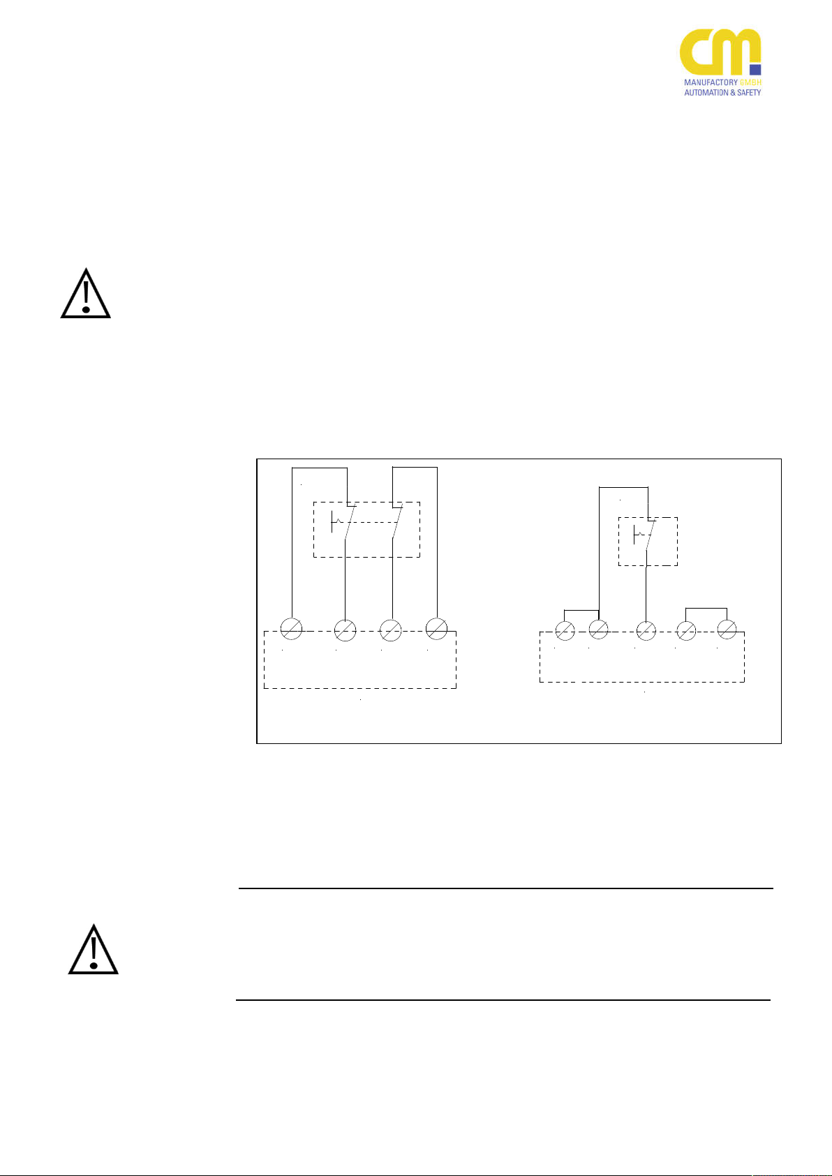
Verdrahtungshinweis für die Ausgangsklemmen 13-14, 23-24, 47-48,
57-58 und 31-32
Spannung (L-Leiter bzw. 24 VAC/DC),
nicht NULL, sollte über die Ausgänge
geschaltet werden um Erd- / Masseschlüsse erkennbar zu machen.
Zur Schonung der Kontakte empfehlen
wir ein RC-Glied parallel zum Verbraucher zu schalten.
Siehe auch im Anwenderhandbuch Kapitel 7, Anwendungsbeispiele für
Erweiterungsmodule.
Example 6: Dual-channel monitoring
of light barrier or light curtain
(ESPE with semiconductor outputs
and short circuit monitoring).
Pressing the START-button, the unit will
be activated. Contacts 13-14, 23-24, 4748 and 57-58 close. An interruption of the
light beam will reset the contacts13-14,
23-24.
Example 7: Dual-channel monitoring
of light barrier or light curtain with external contact extension
(2 contactors).
This application uses two external contactors with positive guidance. One normally closed contact of each external
contactors must be connected in series
to the START-button to the terminals S33
and S34. Through the switch S ext. the
external contactors can be operated or
turned off at any time if the SAFE T is activated. To avoid cross connection, the
external contactors should be wired with
seperate cable sheats.
The device SAFE T makes a complete
self-test. You don’t need an external test
for the safety category 2.
Wiring hints for the output terminals
13-14, 23-24, 47-48, 57-58, and 31-32
Voltages (for example L+ or 24 VAC/DC),
not GND, should be routed via the
terminals. This will help to recognise
shorts to GND or Earth.
Using R-C combination in parallel to
inductive loads can reduce wear out
of contacts.
See also applications guide chapter 7
Connection of the expansion modules
200803
11
Page 12

SAFE T
SAFE T
A1 A2
RESET
Varianten SAFE T / Versions SAFE T
Variante Funktion: Function:
SAFE TN
SAFE TA
SAFE TR
SAFE TU
Nach Drücken des Auslöseelementes (z.B. NotHalt-Schalter) wird die Gleichzeitigkeit gestartet.
Sie beträgt 1s. Innerhalb dieser Zeit müssen bei
zweikanaliger Applikation beide Kanäle betätigt
werden. Nach dieser Zeit bis Ende des Zeitablaufes darf das Auslöseelement nicht mehr betätigt werden (z.B. zurückgenommen werden). Ein
Defekt/ Wackelkontakt am Taster oder am Anschluß kann so sofort erkannt werden.
Das Auslöseelement kann während des kompletten Zeitablaufes betätigt (z.B. zurückgenommen) werden. Die Gleichzeitigkeit beträgt 3s. Erneuter Start erfolgt erst nach Zeitablauf.
Retriggerbare Variante. Das Gerät kann während des Zeitablaufes durch z.B. Rücknahme
des Not-Halt-Schalters retriggert (neu gestartet)
werden. Die Gleichzeitigkeit beträgt 3s.
Das Auslöseelement kann während des kompletten Zeitablaufes betätigt (z.B. zurückgenommen) werden. Es gibt keine Gleichzeitigkeit (unendliche Gleichzeitigkeit). Erneuter Start erfolgt
erst nach Zeitablauf.
After pressing the releasing element (e.g. emergency-button) the simultaneity is started. The
duration is 1 seconds. Within this time both
channels have to be activated if two channel application is used. From activation of both channels till the end of time delay the releasing element may not activated again (e.g. deactivation
of the emergency-button). A failure of the button
or contact is detect immediately.
During the complete time lapse the releasing element can be activated (e.g. deactivation of the
emergency-button). The duration of simultaneity
is 3 seconds. Restart takes place only after timing.
Retriggerable version. The relay is retriggerable
(e.g. new start after deactivation of the emergency-button) during the complete time lapes.
The duration of simultaneity is 3 seconds.
The releasing element can be activated during
the complete time lapes (e.g. deactivation of the
emergency-button). There is no simultaneity
(endless simultaneity). Restart takes place only
after timing.
RESET Hinweis
Im Falle einer Fehlermeldung kann das
Gerät nur durch das Trennen vom Versorgungsnetz neu gestartet werden (RESET). Es empfiehlt sich daher in Reihe
zum A1-Kreis einen Reset-Schalter zu installieren. Die unten stehende Abbildung
verdeutlicht die Installation des ResetSchalters.
RESET tip
In the case of a error message the device
can be started again with a separation
from the supply network only (RESET). It
is advisable to install therefore in row to
the A1-circuit a reset-switch. The illustration standing down clarifies the installation of the reset-switch.
24 V
0 V
200803
12
Page 13

SAFE T
Fehler/Störungen, Auswirkung
und Maßnahmen
Das Sicherheitsrelais SAFE T ist mit einer umfangreichen Fehlerdiagnose ausgestattet. Wird ein Fehler festgestellt,
blinken eine oder beide LEDs von Kanal
1 und Kanal 2. Dabei können u.U. beide
LEDs unterschiedliche Fehler anzeigen.
An der Anzahl der Blinkungen (Blinkcode) kann abgelesen werden, welcher
Fehler aufgetreten ist.
Dabei ist das lange Leuchten der LED
mit zu zählen. Gezählt werden immer die
Lichtimpulse der Leuchtdioden. Das Zählen beginnt mit dem ersten kurzzeitigen
Aufleuchten und geht einschließlich bis
zum langzeitigen Aufleuchten. Die
Summe der gezählten Lichtimpulse ergibt
den Blinkcode. Mit Hilfe der Fehlercodetabelle kann die Fehlerursache lokalisiert
und behoben werden. Blinken die
Leuchtdioden ungleichmäßig dann muss
zuerst die erste Leuchtdiode und anschließend die zweite gemäß der Fehlercodetabelle ausgewertet werden.
Beispiel:
Die LED Kanal 1 blinkt 4 mal
(Blinkcode 4) und LED Kanal 2 blinkt
1 mal (Blinkcode1)
LED Kanal 1 zeigt den Fehler „Ver-
änderung der eingestellten Zeit während
des Betriebes“ an und
LED Kanal 2 zeigt den Fehler „Un-
gleichheit der beiden Kanäle“ an.
Tipp: Blinken beide LEDs, kann der
Blinkcode besser abgelesen werden,
wenn die andere LED abgedeckt wird.
Auf der nächsten Seite finden Sie eine
Aufstellung aller Blinkcodes mit den zugehörigen Erklärungen, den möglichen
Ursachen und Maßnahmen, den Fehler
zu beheben.
Blinkcode 4
error code 4
LED
AN
ON
Troubelshooting
The safety relay SAFE-T is equipped with
comprehensive troubleshooting functions. If an error is discovered, one or
both LED’s of channel 1 or channel 2
begin to flash. Possibly, thereby both
LED’s could indicate different errors.
Which error is occured, can read off by
the number of flashes of the LED’s (error
code). Thereby the long flash have to be
counted also. Always the light pulses of
the light emitting diodes have to be
counted. Counting begins with first shorttime lighting up pulse and goes inclusively up to long-timing lighting up pulse.
The sum of the counted light pulses results in the flashing code. With the help
of the error code table the error cause
can be located and repaired. Flash the
light emitting diodes unevenly then at first
one of the diodes must be evaluate according to the error code table and finally
the other diode.
Example:
LED channel 1 blinks 4 times (error
code 4) and LED channel 2 blinks one
time (error code 1)
LED channel 1 indicates the error
‚Changing of the adjusted time during operation‘
LED channel 2 indicates the error
‚Disparity of both channels‘
Tip: Are flashing both LED’s, the error
code could be better read off, if one of the
LED’s is covered.
On the following page, there is a summary
of all error codes including all declarations, causes and methods to remove the
fault.
200803
3 4
1 2 43
AUS
OFF
Start des
Zählvorgangs
Beginn of the
counting cycle
13
Ende des
Zählvorgangs
End of the
counting cycle
1 2
Zeit
Time
Page 14

SAFE T
Blinkcode
controller meldet sich nicht
bzw. Schutztürwächter) besteht
Gerät austauschen.
Gerät austauschen
an einer Anschlußklemme
schlossen wird
durch Kabelbruch
chronisation)
der Fehlermeldung des anderen Kanals betrachten.
durch nicht fest angeschraubtes Kabel) bzw. Taster prellt länger als
1s
überprüfen, es müssen beide innerhalb
zum Auslöseelement überprüfen
riggerbar)
automatisch (bei automatischem Start)
startet automatisch (bei automatischem Start)
BC
1 automatischer Start mit unterschiedlichen Abfallverzögerungszeiten
Veränderung der eingestellten Zeit vor oder während des Startes
2 Eingangsbeschaltung stimmt nicht Überprüfung der Verdrahtung der Eingangsbeschaltung
3 internes unverzögertes Relais defekt
4 internes zeitverzögertes Relais defekt
5 Signal an S11 bzw. S21 nicht richtig Überprüfung der Verdrahtung der Eingangsbeschaltung
Fehler - mögliche Ursachen Was ist zu tun
Spannung ausschalten, gleiche Abfallverzögerungszeiten einstellen, Spannung einschalten --> Gerät wird wieder gestartet
Start über Start-Taster mit unterschiedlichen Abfallverzögerungszeiten
Ungleichheit der beiden Kanäle bzw. nur ein Kanal bemerkt den
Fehler, Gleichzeitigkeit der Mikrocontroller stimmt nicht, ein Mikro-
bei zweikanaligem Betrieb: Fehlerzustand beim Start wenn beide
Kanäle unterschiedliche Zustände haben ( geöffnet bzw. geschlossen), d.h. wenn die Schutztür nicht komplett offen bzw.geschlossen
ist / oder der Not-Halt-Schalter einen defekten Kanal aufweist oder
wenn ein Kabelbruch zu dem Auslöseelement (Not-Halt-Schalter
S11 mit S21 Querschluß oder S11 bzw. S21 Kurzschluß mit 24VVersorgungsspannung oder S11 bzw. S21 Kurzschluß mit einer anderen positiven Spannung an einer Anschlußklemme
bei einkanaliger Applikation: S11 bzw. S10 Kurzschluß mit 24V
Versorgungsspannung oder mit einer anderen positiven Spannung
Spannung ausschalten, gleiche Abfallverzögerungszeiten einstellen, Spannung einschalten --> Gerät kann wieder gestartet werden
Spannung ausschalten, gewünschte Zeit einstellen, Spannung einschalten --> Gerät kann wieder gestartet werden (bei Start über
Start-Taster) oder startet automatisch (bei automatischem Start)
Fehlermeldung des anderen Kanals betrachten
Schutztüre komplett zumachen / öffnen, Verdrahtung auf Kabelbruch zu dem Auslöseelement überprüfen, Not-Halt-Schalter kontrollieren (auf Defekt)
Eventuell mechanische Lebensdauer des Relais erreicht
Eventuell mechanische Lebensdauer des Relais erreicht
Überprüfung der Verdrahtung der Eingangsbeschaltung
Überprüfung der Verdrahtung der Eingangsbeschaltung
6
7
Gleichzeitigkeit beider Kanäle überschritten
8
bei automatischem Start und noch betätigtem Auslöseelement:
wenn der Rückführkreis erst nach der Wiederbereitschaftszeit ge-
bei automatischem Start und betätigtem Auslöseelement: wenn der
Rückführkreis erst nach ca. 0,5s geschlossen wird nachdem die
Spannungsversorgung an das SAFE T gelegt wird
bei automatischem Start und betätigtem Auslöseelement: wenn die
Brücke für den automatischen Start wieder geöffnet wird, z.B.
Veränderung der eingestellten Zeit während der Abfallverzögerung
oder Wiederbereitschaftszeit
interner Fehler im Interrupt (ROM-Test nicht o.k., Fehler in der Syn-
bei zweikanaligem Betrieb: es wurde nur ein Kanal abgeschaltet,
ein Not-Halt-Schalter ist verklebt oder öffnet nicht
Defekt/Wackelkontakt am Taster oder am Anschluß (eventuell
bei zweikanaligem Betrieb: Entriegelung des Not-Halt-Schalters /
Öffnen der Schutztüre vor Ablauf der Abfallzeit (Gerät ist nicht ret-
SAFE T wurde mit zwei unterschiedlichen Zeiten gestartet (Zeiten
wurden in spannungslosen Zusand eingestellt)
bei einkanaligem Betrieb: Brücke S21,S22 wird im aktiven Gerätezustand (Relais angezogen) geöffnet
Veränderung der eingestellten Zeit während des Betriebes (Relais
angezogen, Auslöseelement nicht betätigt)
Verdrahtung zum externen Schütz/ zu den externen Schützen
überprüfen, Funktion der Schütz/e überprüfen
Verdrahtung zum externen Schütz/ zu den externen Schützen
überprüfen, Funktion der Schütz/e überprüfen
Verdrahtung zum externen Schütz/ zu den externen Schützen
überprüfen, Funktion der Schütz/e überprüfen
Spannung ausschalten, gewünschte Zeit einstellen, Spannung einschalten --> Gerät kann wieder gestartet werden (bei Start über
Start-Taster) oder startet automatisch (bei automatischem Start)
Gerät austauschen und ggf. zur Garantie/Reparatur einschicken o-
Verdrahtung zu dem Auslöseelement überprüfen, Funktion des
Auslöseelementes überprüfen
Verdrahtung zu dem Auslöseelement überprüfen, Funktion des
Auslöseelementes überprüfen
Position der Schutztürtaster
einer Sekunde gedrückt oder losgelassen werden, Verdrahtung
Gerät reseten (Spannung kurz ausschalten) danach Gerät kann
wieder gestartet werden (bei Start über Start-Taster) oder startet
Spannung ausschalten, gewünschte Zeit bei beiden Schaltern und
am Dip-Schalter gleich einstellen, Spannung einschalten --> Gerät
kann wieder gestartet werden (bei Start über Start-Taster) oder
Verdrahtung zu S21 und S22 überprüfen
Spannung ausschalten, gewünschte Zeit einstellen, Spannung einschalten --> Gerät kann wieder gestartet werden (bei Start über
Start-Taster) oder startet automatisch (bei automatischem Start)
200803
14
Page 15

SAFE T
Code
ton) or device starts automatically (by self-acting start)
a faulty channel or if there is a cable break which is connected
to the emergency-button resp. safety-gate watcher
>
replace the relay
>
replace the relay
connecetd to any clamp
resp. push-button bounces longer as 1s
not retriggerable)
device starts automatically (by self-acting start)
button) or device starts automatically (self-acting start)
ton) or device starts automatically (by self-acting start)
Flashing
1
2
3
4
5
Errors - possible causes What to do
self-acting start with different switch-off delay
start over start-button with different switch-off delay
changing of adjusted time before or during the start
disparity of both channels resp. only one channel notice the
error, simultaneity of the microcontroller is wrong, no acknowledgment of one microcontroller
input circuit is wrong check wiring of input circuit
at two-channel operation: error state at start if both channels
have different states (e.g. opened or closed), i.e. if safety gate
is not complete open resp. closed / or emergency-button has
internal instantaneous relay is damaged
internal time-delay relay is damaged
signal of pin S11 resp. pin S22 has a wrong value check wiring of input circuit
transverse conclusion of pin S11 with pin S21, or short-circuit
of pin S11 resp. pin S21 with 24V supply voltage or short-circuit of pin S11 resp. pin S21 with another positive voltage
connected to any clamp
at one-channel application: short-circuit of pin S11 resp. pin
S10 with 24V supply voltage or with another positive voltage
switch off supply voltage, adjust same switch-off delay, switch
on supply voltage -> device will be start again
switch off supply voltage, adjust same switch delay, switch on
supply voltage -> device could start again
switch off supply voltage, adjust favored time, switch on supply voltage --> device could start again (by start with start-but-
look at the error message of the other channel
close or open the safety-gate complete, check the wiring
which is connected to the releasing element, check the emergency-button (defect)
maybe the max. mechanical lifetime of the relay is reached --
maybe the max. mechanical lifetime of the relay is reached --
check wiring of input circuit
check wiring of input circuit
by self-acting start and still activated releasing element: if the
feedback loop is closed not until after standby-time
by self-acting start and activated releasing element: if the
feedback loop is closed not until after approx. 0.5s after the
relay SAFE-T is connected to the supply voltage
by self-acting start and activated releasing element: if the
bridge for self-acting start will be opened, i.g cable break
6
7
8
changing of adjusted time during the switch-off delay or
standby-time
internal interrupt error (ROM test failed, synchronization error)
at two-channel operation:only one channel was switched off,
one emergency-button does not open or is clotted
there is a defect/bad contact on the push-button or connector
(maybe because of a cable which is not correctly screwed on)
overstep of simultaneity of both channels
at two-channel operation: unlocking of the emergency-button,
unclose the safety-gate before the fall time runs off (device is
SAFE-T was started with two different times (times were adjusted in a condition without supply voltage)
at one-channel operation: bridge S21, S22 will be opened
while the device is in an active condition (relay is activated)
changing of the adjusted time during operation (relay is activated, releasing element is not activated)
check wiring to the external contactor/contactors, check the
function of the external contactors
check wiring to the external contactor/contactors, check the
function of the external contactors
check wiring to the external contactor/contactors, check the
function of the external contactors
switch off supply voltage, adjust favored time, switch on supply voltage --> device could start again (by start with start-button) or device starts automatically (by self-acting start)
replace device, if necessary send it in because of garanty or
repair, or look at the error message of the other channel
check the wiring to the releasing element, check the function
of the releasing element
check the wiring to the releasing element, check the function
of the releasing element
check the position of safe-gate button, both buttons have to
pushed or unhanded within 1s, check the wiring to the releasing element
reset the device (short switch off the supply voltage), after
that, the device could start again (by start with start-button) or
switch off supply voltage, adjust favored time at both buttons
and at the DIP-switch (must be the same value), switch on
supply voltage --> device could start again (by start with start-
check the wiring to S21 and S22
switch off supply voltage, adjust favored time, switch on supply voltage --> device could start again (by start with start-but-
200803
15
Page 16

SAFE T
Gerätevarianten / Devices
Name / Name: Spannung / Voltage: Artikel-Nummer. / Article number:
SAFE TN 24 V AC / DC 45024
SAFE TA 24 V AC / DC 45025
SAFE TR 24 V AC / DC 45209
SAFE TU 24 V AC / DC 45026
200803
16
 Loading...