

Page 1
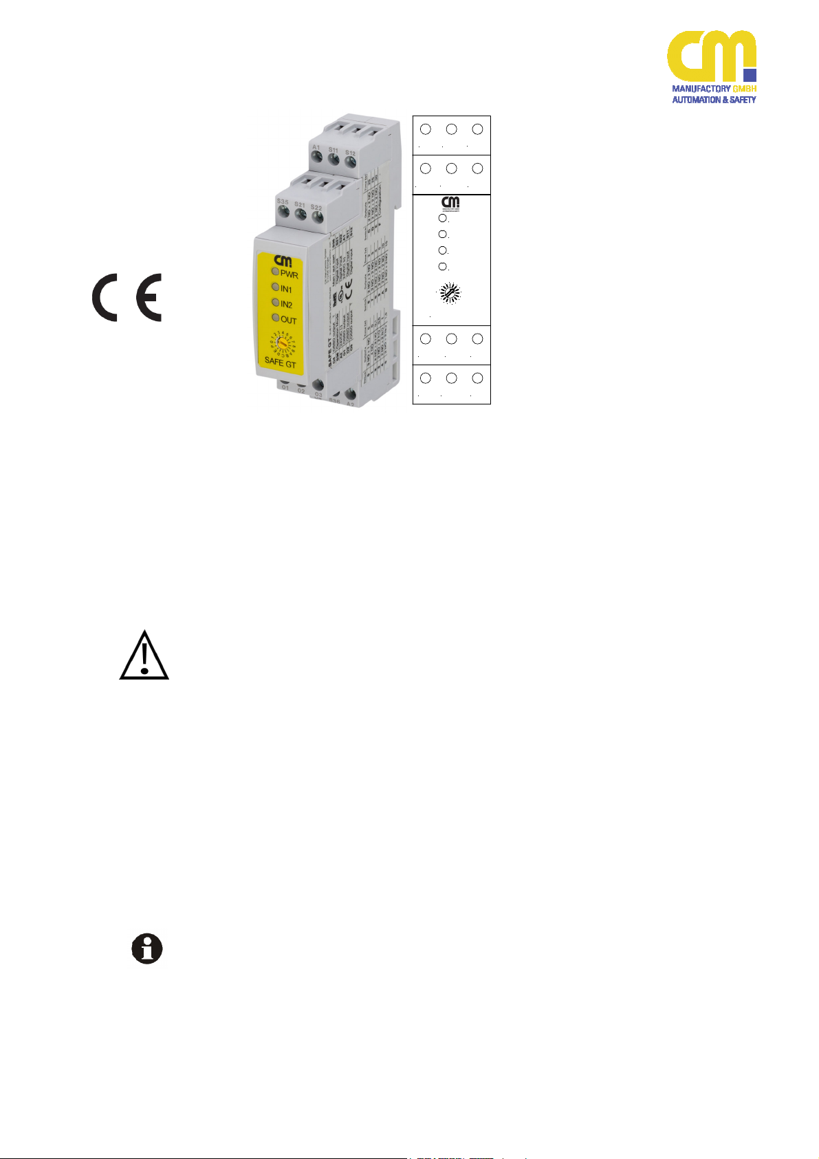
SAFE GT G1 G2 GL
CM Manufactory GmbH
Otto-Hahn-Str. 3
D-72406 Bisingen
Tel. +49-(0)7476-9495-0
Fax. +49-(0)7476-9495-195
www.cm-manufactory.com
www.cm-gruppe.eu
S21
PWR
IN1
IN2
OUT
4
5
3
2
1
0
P
E
D
C
SAFE GT
O2
S12
S22
6
7
8
9
A
B
O3
A1 S11
S35
O1
O4 S36 A2
Gültigkeit des Dokuments
Dieses Dokument bezieht sich ausdrücklich nur auf die angegebene Geräteversion. Bitte vergleichen Sie die auf dem
Gerät aufgebrachte Geräteinformation
mit der Version dieser Bedienungsanleitung.
Es liegt in der Verantwortung des Anwenders zu entscheiden, ob sich das
Gerät für die gestellte Aufgabe eignet.
Bitte verwahren Sie das Dokument an
einer leicht zugänglichen, trockenen
Stelle, so dass es jederzeit zu Rate gezogen werden kann.
Einleitung
Diese Bedienungsanleitung soll Sie mit
den Sicherheitsnachschaltgeräten
SAFE GT
SAFE G1
SAFE G2
SAFE GL
vertraut machen.
Die nachfolgende Bedienungsanleitung
bezieht sich, wenn nicht explizit anders
beschrieben, auf alle vier Geräte.
SAFE GT
SAFE G1
SAFE G2
SAFE GL
Original Bedienungsanleitung
Original Operating Instruction
Multifunktionales Sicherheitsnachschaltgerät für
- Not-Halt / Schutztürwächter
- BWS Typ2 und Typ4
- Sicherheitsmatten
Multifunctional Safety Device for
- Emergency Stop and Safety Gate
Devices
- ESPDs Type 2 and Type 4
- Safety Mats
© Copyright CM Manufactory, D-72406 Bisingen
Alle Rechte vorbehalten.
Änderungen, die dem technischen Fortschritt
dienen, vorbehalten.
All rights reserved. The information in this manual
is subject to change without notification.
Validity of this Document
This document explicitly takes place only
on SAFE G devices with the identical
version. Please compare the version
state on the device with the one of this
manual.
It is the responsibility of the user to decide, if the appropriate SAFE G is suitable for the given function.
Please keep this document at an easily
accessible and dry place, to be able to
get its information at any time.
Introduction
This operating instruction will make you
familiar with the following safety relays
SAFE GT
SAFE G1
SAFE G2
SAFE GL
The following manual points, otherwise
described anomalously explicitly, to all 4
devices.
270220 1
Page 2
SAFE GT G1 G2 GL
SAFE GT
SAFE G1
SAFE G2
SAFE GL
Zu Ihrer Sicherheit
For Your Safety
Gerätevarianten
Das SAFE GT ist ein multifunktionales
Sicherheitsnachschaltgerät mit einstellbarer Sicherheitsfunktion, wählbarer
Ausgangskonfiguration und zuschaltbarer Zeitverzögerung im Bereich von 0,1s
bis 30s.
Das SAFE G1 ist ein multifunktionales
Sicherheitsnachschaltgerät mit einstellbarer Sicherheitsfunktion und fester
Ausgangskonfiguration (3 Schließer, 1
Öffner, jeweils ohne Zeitverzögerung).
Das SAFE G2 ist ein multifunktionales
Sicherheitsnachschaltgerät mit einstellbarer Sicherheitsfunktion und fester
Ausgangskonfiguration (4 Schließer,
ohne Zeitverzögerung).
Das SAFE GL wurde ausdrücklich entwickelt für Aufzuganwendungen. Es ist
zugelassen nach EN81-20 und
EN81-50. Es ist ein multifunktionales
Sicherheitsnachschaltgerät mit einstellbarer Sicherheitsfunktion und fester
Ausgangskonfiguration (3 Schließer,
1 Öffner, jeweils ohne Zeitverzögerung).
Bestimmungsgemäße
Verwendung
Die bestimmungsgemäße Verwendung
der SAFE-G-Geräte ist als sichere
Nachschaltgeräte für den Einsatz von:
- Not-Halt-Anwendungen ein- oder
zweikanalig
- Schutztür-Anwendungen ein- oder
zweikanalig
- Berührungslos wirkende Schutzeinrichtungen (BWS) Typ 4 wie z.B.
Lichtschranken, Lichtgitter, Lichtvorhänge.
- Testbare berührungslos wirkende
Schutzeinrichtungen (BWS) Typ 2 wie
z.B. Lichtschranken, Lichtgitter, Lichtvorhänge. Das SAFE G generiert den
Testimpuls und überwacht die Reaktion der BWS.
- Sicherheitsmatten, Sicherheitsbumper, Sicherheitsschaltleisten jeweils in
4-Draht-Ausführung.
Personen- und Sachschutz sind nicht
mehr gewährleistet, wenn das Sicherheitsnachschaltgerät nicht entsprechend seiner bestimmungsgemäßen Verwendung eingesetzt wird.
Variants
SAFE GT is a multifunctional safety device with configurable safety function,
selectable output configuration and additional time delay within 0,1s up to 30s.
SAFE G1 is a multifunctional safety device with configurable safety function
and fixed output configuration (3NO,
1NC, all undelayed).
SAFE G2 is a multifunctional safety device with configurable safety function
and fixed output configuration (4NO,
undelayed).
SAFE GL was explicitly developed for lift
applications. It is approved according to
EN81-20 and EN81-50. It is a multifunctional safety device with configurable
safety function and fixed output configuration (3NO, 1NC, all undelayed)
Intendend Use
The intended use of the SAFE G devices
is as safety devices for
- Emergency stop applications
one or dual channel
- Safety gate applications one or
dual channel
- Electro sensitive protected devices (ESPD) type 4 like light
barriers, light curtains, light
grids.
- Testable electro sensitive protected devices (TSPD) type 2
like light barriers, light curtains,
light grids. SAFE G is generating
the testing pulse.
- Safety mats, safety bumpers,
safety rails in 4-wire type each.
Operator and object protection isn’t
guaranteed, if the safety relay isn’t be
used in its intended manner.
270220 2
Page 3
SAFE GT G1 G2 GL
Zielgruppe
Target Group
Sicherheitshinweise
Die Bedienungsanleitung richtet sich an
folgende Personen:
Qualifizierte Fachkräfte, die Sicher-
heitseinrichtungen für Maschinen
und Anlagen planen und entwickeln
und mit den Vorschriften über Arbeitssicherheit und Unfallverhütung
vertraut sind.
Qualifizierte Fachkräfte, die Sicher-
heitseinrichtungen in Maschinen und
Safety Hints
The operating instruction is addressed to
the following persons:
• Skilled personnel, who plan or develop safety equipment for machines
and plants and are familiar with the
safety instructions and safety regulations.
• Skilled personnel, who install safety
equipment in machines and plants
and put them into operation.
Anlagen einbauen und in Betrieb
nehmen.
Nützliche Links Useful Links
CM-Gruppe
CM-Group
Zeichenerklärung
Legend To Signs
In dieser Bedienungsanleitung werden
einige Symbole verwendet, um wichtige
Informationen hervorzuheben:
Dieses Symbol steht vor Textstellen, die
unbedingt zu beachten sind. Nichtbeachtung führt zur Verletzung von Personen
oder zu Sachbeschädigung.
Dieses Symbol kennzeichnet Textstellen, die wichtige Informationen enthalten.
Dieses Zeichen kennzeichnet auszuführende Tätigkeiten.
Nach diesem Zeichen wird beschrieben,
wie sich der Zustand nach einer ausgeführten Tätigkeit ändert.
Beachten Sie unbedingt die folgenden Punkte:
Das Gerät darf nur unter Beachtung
dieser Bedienungsanleitung von Fachpersonal installiert und in Betrieb genommen werden, das mit den geltenden
Vorschriften über Arbeitssicherheit und
Unfallverhütung vertraut ist. Elektrische
Arbeiten dürfen nur von Elektrofachkräften durchgeführt werden.
Beachten Sie die jeweils gültigen
Vorschriften, insbesondere hinsichtlich der Schutzmaßnahmen.
The operating instruction contains several symbols which are used to high-light
important information:
This symbol shows text passages which
must be noticed. Non-observance leads
to serious injuries or damage of property.
This symbol shows passages which
contain important information.
This sign is placed for activities.
After this sign it is described how the
state changes after an executed activity.
Please pay attention to the following
points:
The device must only be built in and
operated by specialised staff, which is
familiar with this instruction and the current regulations for safety at work and
accident prevention. Working on electrical equipment is only allowed for specialised staff.
Pay attention to valid regulations,
particularly in reference to preventative measures.
270220 3
Page 4
SAFE GT G1 G2 GL
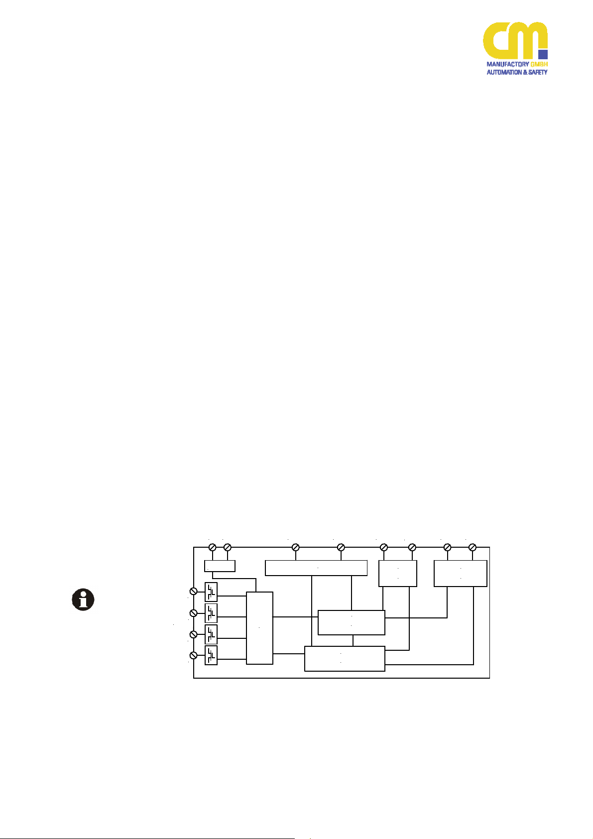
Blockschaltbild
Block Diagram
Reparaturen, insbesondere das
Öffnen des Gehäuses, dürfen nur
vom Hersteller oder einer von ihm
beauftragten Person vorgenommen
werden. Ansonsten erlischt jegliche
Gewährleistung. Ferner kann die Sicherheit des Bedieners nicht länger
gewährleistet werden.
Montieren Sie das Gerät in einem
staub- und feuchtigkeitsgeschützten
Gehäuse (IP54 oder besser). Staub
und Feuchtigkeit können zu Funktionsstörungen führen.
Sorgen Sie für eine ausreichende
Schutzbeschaltung bei kapazitiven
und induktiven Lasten an den Ausgangsklemmen (z.B. Freilaufdiode
bei induktiven Lasten).
Beachten Sie unbedingt die Anga-
ben in den Technischen Daten. Verhindern Sie ein Überschreiten der
Grenzwerte.
Alle SAFE G sind intern mit einer
Schmelzsicherung 2,5A versehen
(Trennvermögen 50A/125V).
In regelmäßigen Zeitabständen sollte
das Sicherheitsnachschaltgerät ausgelöst werden und auf korrekte Funktion
geprüft werden (mindestens jedes halbe
Jahr oder im Wartungszyklus der Anlage), vgl. Anhang B.
Aufbau und Funktionsweise
A1 A2
Power
O4
O3
O2
Release Outputs
O1
Safety output
S12 S22
Input circuits
circuits
<Controller 2>
<Controller 1>
MCU2
Structure and Function
MCU1
Any repairs have to be done by the
manufacturer or a person which is
authorised by the manufacturer only.
It is prohibited to open the device or
implement unauthorised changes,
otherwise any warranty expires.
The unit should be panel mounted in
an enclosure rated at IP 54 or better,
otherwise dampness or dust may
lead to malfunction.
Adequate fuse protection must be
provided on all output contacts with
capacitive and inductive loads.
Pay attention to the technical data
values. Never overrun the limitations.
All SAFE G devices are internally
equipped with a melting fuse 2,5A
(Short Circuit Withstand 50A/125V)
The safety relay should be tested in a
defined time period (every six months or
after each check of the plant), see also
appendix B.
S11
Output
circuits
S21
S35
Combination
circuit
S36
Spannungsversorgung +24VDC
A1
Spannungsversorgung Masse
A2
Aktivierungsausgang Kanal 1
S11
Aktivierungsausgang Kanal 2
S21
Triggereingang Kanal 1
S12
Triggereingang Kanal 2
S22
Eingang Start und Startkonfiguration
S35
Eingang Konfiguration
S36
O1, O2, O3, O4
270220 4
Sichere Ausgänge OSSDs
Power Supply +24VDC
Power Supply Gnd
Trigger output channel 1
Trigger output channel 2
Trigger input channel 1
Trigger input channel 2
Input start and start configuration
Input configuration
Safe outputs OSSDs
Page 5
SAFE GT G1 G2 GL
Die Aktivierungs- und Eingangskontakte
sind entsprechend des Verwendungszweckes zu verdrahten
(s. „Montage und Inbetriebnahme“).
Der Aktivierungsausgänge S11 und S21
des Gerätes sind kurzschlussfest. Sie
werden getaktet und von den internen
Kontrollern unabhängig überwacht.
Mittels S35 wird das Startverhalten festgelegt.
S36 ist ein weiterer Konfigurationseingang
Spannungsversorgung
Power Supply
Montage
Mounting
Elektrischer
Anschluss
Electric Wiring
24VDC ±20%
Die Spannungsversorgung muss den Anforderungen der EN61496-1 entsprechen.
Montage und Inbetriebnahme
Für eine sichere Funktion muss das Sicherheitsnachschaltgerät in ein staub- und
feuchtigkeitsgeschütztes Gehäuse (IP54
oder besser) eingebaut werden.
Montieren Sie das Gerät auf eine
Normschiene (35mm). Achten Sie
hierbei darauf, dass die Befestigungsfeder einrastet.
Führen Sie die Verdrahtung entsprechend
des Verwendungszweckes durch. Orientieren Sie sich dabei an den Anwendungsbeispielen weiter unten. Generell ist das
Sicherheitsnachschaltgerät nach den folgenden Angaben zu verdrahten und einzustellen:
1. Montageort
Montieren Sie das jeweilige Gerät
SAFE G auf eine Normschiene innerhalb eines Gehäuses (Schaltschrank)
mit mindestens IP54.
Es ist empfehlenswert, das Gerät nicht
benachbart mit starken Störquellen
(Netzteile, Motoransteuerungen, Motoren,…) zu betreiben.
2. Versorgungsspannung anschließen
Die Versorgungsspannung wird an die
Klemmen A1 (+24VDC) und A2 ("-„
oder Gnd) angeschlossen. Nach dem
Anlegen der Betriebsspannung führt
das Gerät einen Selbsttest von ca. 6s
durch.
The activation and input contacts need to
be wired according to the intended purpose (see "Mounting and start-up").
The activation outputs S11 and S21 of the
device are short-circuit-proof. The output
signals are clocked and independently
monitored by the internal controllers.
Via S35 the start behaviour is fixed.
S36 is a further configuration input needed
for the wired configuration declaration.
24VDC ±20%
The power supply has to fulfil the requirements of the EN61496-1.
Mounting and start-up
The unit must be panel mounted in an
enclosure rated at IP 54 or better, otherwise dampness or dust could lead to malfunction.
There is a notch on the rear of the unit
to attach it on DIN-Rail. Please see
that the clip locks accurately.
Carry out the wiring according to the chosen application. You will find some examples for applications later on in this manual. In general the safety relay has to be
wired as follows:
1. Installation site
Attach the respective SAFE G device
on a DIN rail inside a housing (control
cabinet) with IP protection of at least
IP54.
It is recommended, not to use the
SAFE G device directly adjacent to or
between other electrical equipment
(power supplies, motor drives) and
wires.
2. Connect Power Supply
Connect the power supply to the terminals A1 (+24VDC) and A2 ("-" or
Gnd). After switching on the power
supply the SAFE G performs an internal self-test.
270220 5
Page 6

SAFE GT G1 G2 GL
Danach ist das Gerät betriebsbereit.
Jegliche Konfigurationsänderungen
sind nach dem Anlegen der Versorgungsspannung nicht mehr erlaubt.
Da das SAFE G nur durch Wegnahme
der Versorgungsspannung resettet
werden kann, empfiehlt es sich, einen
Taster (Öffner) in den Versorgungsspannungskreis aufzunehmen.
3. Startkreis und Rückführkreis anschließen
Die Rückführung (Brücke oder Öffnerkontakte der externen Schütze in Reihe) wird in den Startkreis verdrahtet
(siehe "Festlegung des Startverhaltens").
4. Verdrahtung der Funktionalität
Verdrahten Sie das SAFE G entsprechend den Angaben siehe "Einstellen
der Funktion".
Alternative Möglichkeit
1. Sie können das SAFE G auch mit Hilfe
einer Beispielapplikation verdrahten
(incl. Startkreis).
Besonders zu berücksichtigen
Eingriffe am Sicherheitsnachschaltgerät
SAFE G sind ausdrücklich untersagt, anderweitig kann die Sicherheit des Bedieners nicht länger gewährleistet werden.
Störungen aufgrund von induktiven und
kapazitiven Einstreuungen sind zu vermeiden. Hierzu kann es notwendig sein, Anschlussleitungen von Sensoren von Motorleitungen oder anderen Stromleitungen
getrennt zu verlegen.
Halten Sie diese Bedienungsanleitung
bereit. Lagen Sie sie an einem trockenen
Ort.
Beachten Sie auch die Gültigkeit der Bedienungsanleitung.
After the internal test the SAFE G is
ready to use. Now all changing of the
configuration is prohibited.
The SAFE G can only be reset by disconnecting the power supply. For this
it is recommended to add a push button (NC) in the supply circuit.
3. Connect Start Circuit and Feedback
Circuit
The feedback of the external relay or
contactors (bridge if not needed or the
NCs switched in series) will be
mounted within the start circuit (see
"Fixing of the Start Behaviour").
4. Connection of the functionality
Wire SAFE G intendent to the needed
functionality regarding the details in
"Adjusting the Configuration"
Alternative Option
1. You may want to wire SAFE G using
one of our sample applications (incl.
start circuit)
Especially to Notify
Tampering with the device SAFE G in any
way are strictly prohibited. Otherwise the
safety of the plant and the users is no
longer valid.
Malfunctions due to inductive and capacitive have to be avoided (Crosstalk). For
this it might be helpful to route the wires
separately.
You should keep this manual available.
Store it on a dry place.
Please observe also the validation of this
manual.
270220 6
Page 7
SAFE GT G1 G2 GL
S11
S12
S21
S22
Gerät anschließen
Mounting
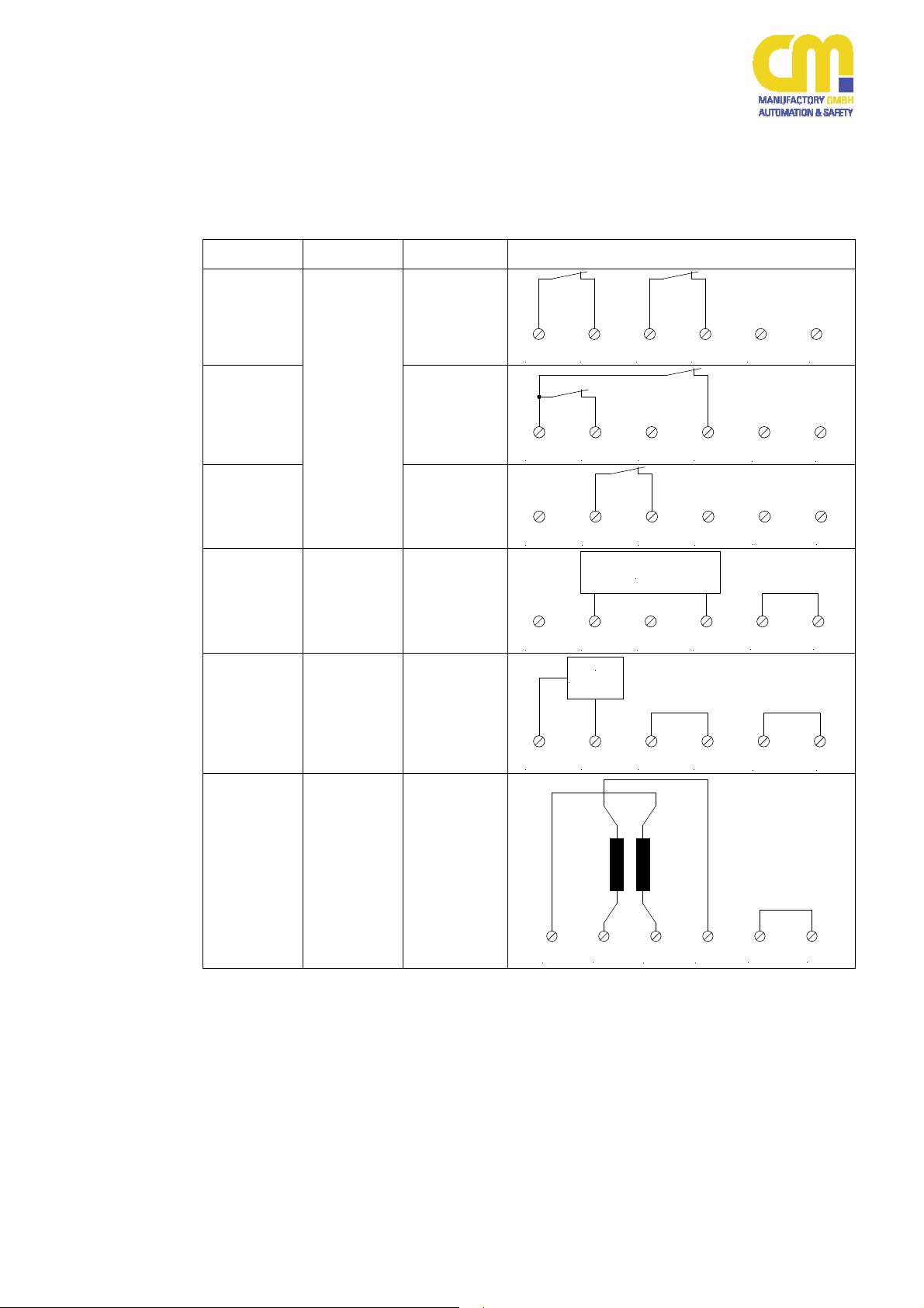
Konfigurationen
Configurations
Einstellen der Funktion
Durch die Verdrahtung wird festgelegt, welche
Funktion das Gerät ausführen soll.
Konfiguration
configuration
SC1
SC2
Funktion
operation
Nothalt
Schutztürwächter
E-Stop
E-Gate
Option
option
2 Kanäle
4-Draht
2 channel
4 wires
2 Kanäle
3-Draht
2 channel
3 wires
Adjusting the Configuration
By wiring the configuration of the device will
be adjusted.
Verschaltung
wiring
S11 S12 S21 S22 S36 A2
SC3
SC4
SC5
SC6
BWS
Typ 4*)
ESPD
type 4*)
BWS Typ
2**)
ESPD
type 2**)
Sicherheitsmatte
Safety Mat
1 Kanal
2-Draht
1 channel
2 wires
2 Kanäle
3-Draht
2 channel
3 wires
1 Kanal,
testbar
2-Draht
1 channel
testable
2 wires
4-Draht
4 wires
S11 S12 S21 S22
2x PNP
S11 S12 S21 S22
PNP
T
S11 S12 S21 S22
S36 A2
S36 A2
S36 A2
S36 A2
*) in der Konfiguration SC4 ist den Eingängen S12, S22 ein 1ms-Filter zugeschaltet.
An 1ms-filter has been added to the inputs in SC4
**) Mehrere BWS Typ2 können kaskadiert werden.
Several ESCD-type2-devices may be cascaded
270220 7
S12 S21 S22
S11
S36 A2
Page 8

SAFE GT G1 G2 GL
Erkennung der
Konfiguration
Recognizing of
the Configuration
Während der Startphase (nach dem RAMTest; ca. 6s) ermittelt das SAFE G die verdrahtete Konfiguration. Hierzu werden die Ausgänge S11 und S21 wechselweise geschaltet um
die elektrische Verbindung zu prüfen. Nachdem eine Konfiguration eindeutig feststeht,
geht das Gerät in seinen normalen Modus, die
Ausgänge werden entsprechend der Ausgangskonfiguration geschaltet (bis zur Erkennung der Eingangskonfiguration sind alle Ausgänge (Triggerausgänge, OSSDs, auch die mit
Öffner-Funktion) abgeschaltet!).
Sind die angeschlossenen Triggerelemente
aktiv, und liegt eine entsprechende Startbedingung vor, schalten die OSSDs in den aktiven Zustand (die Ausgänge mit Schließerfunktion führen 24VDC und die Ausgänge mit Öffnerfunktion sind abgeschaltet).
Hinweis: Sind an der zu erkennenden Konfiguration offene Triggerelemente beteiligt, so wird
auf das Schließen der Triggerelemente gewartet (SC1, SC2, SC3).
Hinweis: SC4, SC5 und SC6 können unabhängig vom Zustand der BWS erkannt werden.
During the start phase (after the RAM-Test of
app. 6s) SAFE G calculates the wired configuration. For this the outputs S11 and S21 are
switched alternately to check the electrical
wiring. After the configuration has been fixed,
the SAFE G device goes into its normal mode,
the outputs are switched due to the recognized
configuration. (Up till now the trigger outputs
and all OSSDs are switched off, even the
NCs.).
If the wired trigger elements are activated and
the start condition is valid, the OSSDs switch
into the active state, which means that the NO
outputs have 24VDC and the NC output has
0V (is switched off).
Hint: If the configuration to be recognized contains open trigger elements, the SAFE G will
wait until they are closed (SC1, SC2, SC3).
Hint: SC4, SC5 and SC6 can be recognized
regardless of the involved trigger elements.
270220 8
Page 9

SAFE GT G1 G2 GL
S35
S11
S21
Gerät anschließen
Mounting
the Device
Festlegung des Startverhaltens / Fixing of the Start Behaviour
# Modus
# mode
Startmodus
start mode
Manueller Start (mit Überwachung der Starttaste)
Manual start (start button monitored)
MS1a
Manueller Start mit Überwachung externer Schütze
manual start with feedback of external contactors expansion
MS1b
Verdrahtung
wiring
Start
S35 S11 S21
Start
K1ext
K2ext
MS2a
MS2b
MS2c
270220 9
Manueller Start
Beim Manuellen Start wird der Starttaster überwacht. Die OSSDs werden aktiv bei einem
Wechsel der Eingangsspannung von HIGH nach
LOW (Loslassen des Tasters). Damit kann ein
fehlerhaftes Dauer-High oder Dauer-Low am
Starteingang nicht zu einer gefährlichen Situation
führen.
Automatischer Start
Beim Automatischen Start wird der Starttaster
nicht überwacht, damit ist auch der Einsatz eines
Schalters oder auch eine Brücke möglich. Die
OSSDs werden aktiv bei einem Wechsel von
LOW nach HIGH am Starteingang (Drücken des
Automatischer Start
automatic start
Automatischer Start ohne Überwachung des Startkontakts
automatic start without monitoring of the start button
Automatischer Start ohne Überwachung des Startkontakts
und Überwachung externer Schütze
automatic start with monitoring of external contactors
Manual Start
In manual start mode, the start button is monitored. The OSSDs become active when the input
voltage changes from HIGH to LOW. Thus a
faulty continuous high or continuous low at the
start input cannot lead to a dangerous situation.
Automatic Start
With the automatic start the start button is not
controlled, so it is also possible to use a switch or
a bridge. The OSSDs are activated on a change
on the start input from LOW to HIGH (pressing
the button). In case of a permanent HIGH the
S35 S11 S21
Start
S35 S11 S21
Start
K1ext
K2ext
S35 S11 S21
Page 10

SAFE GT G1 G2 GL
Tasters). Bei einem dauerhaften HIGH-Signal am
Starteingang werden die Ausgänge sofort HIGH,
wenn auch die Triggereingänge aktiviert werden.
SicherheitsHinweise
Safety
Hints
Bitte beachten Sie, dass eine Nothalt-Applikation
mit automatischem Start (ohne Überwachung der
Starttaste) nicht zulässig ist!
Die Starttaste muss sich außerhalb des Gefahrenbereichs befinden in einer Position, die den
Einblick in den Gefahrenbereich und den Arbeitsbereich leicht ermöglicht.
Für den Einsatz als Zugangsüberwachung entsprechend der EN61496 ist manueller Start
zwingend vorgeschrieben.
Zur Überwachung externer zwangsgeführter oder
gespiegelter Relais oder Schütze können die
Öffnerkontakte in Reihe in den Startkreis geschaltet werden.
nur
SAFE GT
only
Programmierung (nur SAFE GT)
Einstellbare Ausgangskonfiguration
(OSSDs)
outputs will become active immediately after
activating the trigger inputs.
Please note that an emergency stop application
together with automatic start (without controlling
of the start button) is not allowed!
The start bottom has to be outside the danger
area at a position, where the danger area can be
easily observed.
For the use as an access monitoring device according to EN61496 a manual start is mandatory.
For controlling of external contactors their NCs
can be put in series into the start circuit.
Programming (only SAFE GT)
Adjustable output Configuration
(OSSDs)
Ausgangskonfiguration
Position
Hexschalter
0 3 NO / 1 NC – direkt 0
1 4 NO – direkt 0
2 2 NO direkt / 2 NO verzögert 0,1
3 2 NO direkt / 2 NO verzögert 0,5
4 2 NO direkt / 2 NO verzögert 1
5 2 NO direkt / 2 NO verzögert 1,5
6 2 NO direkt / 2 NO verzögert 2
7 2 NO direkt / 2 NO verzögert 3
8 2 NO direkt / 2 NO verzögert 4
9 2 NO direkt / 2 NO verzögert 5
A 2 NO direkt / 2 NO verzögert 10
B 2 NO direkt / 2 NO verzögert 15
C 2 NO direkt / 2 NO verzögert 20
D 2 NO direkt / 2 NO verzögert 25
E 2 NO direkt / 2 NO verzögert 30
P Prog
s
Position of
Verzögerung /
hex-switch
Output Configuration
Delay / s
0 3 NO / 1 NC – no delay 0
1 4 NO – no delay 0
2 2 NO direct / 2 NO delayed 0,1
3 2 NO direct / 2 NO delayed 0,5
4 2 NO direct / 2 NO delayed 1
5 2 NO direct / 2 NO delayed 1,5
6 2 NO direct / 2 NO delayed 2
7 2 NO direct / 2 NO delayed 3
8 2 NO direct / 2 NO delayed 4
9 2 NO direct / 2 NO delayed 5
A 2 NO direct / 2 NO delayed 10
B 2 NO direct / 2 NO delayed 15
C 2 NO direct / 2 NO delayed 20
D 2 NO direct / 2 NO delayed 25
E 2 NO direct / 2 NO delayed 30
P Prog
270220 10
Page 11

SAFE GT G1 G2 GL
nur
SAFE GT
only
nur
SAFE GT
only
nur
SAFE GT
only
nur
SAFE GT
only
Programmierung der Ausgangskonfiguration
(OSSDs)
Benötigtes Werkzeug: kleiner Schraubendreher.
PWR
IN1
IN2
OUT
4
5
3
6
2
7
1
8
0
9
P
A
E
B
D
C
SAFE GT
1. Gerät muss ausgeschaltet sein
2. Hexschalter in Position P stellen
3. Gerät einschalten, ca. 6s warten bis die
PWR- und OUT-LED wechselweise blinken.
4. Den Hexschalter im Uhrzeigersinn zügig in
die gewünschte Position drehen (siehe obige
Tabelle)
5. ca. 2 Sekunden warten
6. die PWR- und OUT-LED blinken wechselweise schnell, die Einstellung wurde übernommen
7. Gerät aus- und wieder einschalten, das Gerät
arbeitet nun mit der neuen Einstellung.
Hinweise zur Programmierung
Die korrekte Funktion des Hexschalters wird
während der Programmierung überprüft.
Der Hexschalter sollte nur während der Programmierung bewegt werden, eine nicht-korrekte
Stellung des Hexschalters führt dazu, dass das
Gerät in den FAILSAFE geht (Fehlercode 34).
Die Programmierung kann beliebig oft durchgeführt werden (bzw. nach einem Fehler wiederholt
werden).
Sollte bei der Programmierung die gewünschte
Stellung überfahren worden sein, einfach im
Uhrzeigersinn an die gewünschte Position weiterdrehen (es sind beliebig viele Umdrehungen
möglich)
Wenn die Versorgungsspannung abgeschaltet
ist, kann der Hexschalter in jede Richtung bewegt werden.
Während der Programmierung sind alle Ausgänge (Triggerausgänge und OSSDs) abgeschaltet.
Programming of the Output Configuration
(OSSDs)
Necessary tool: small screw driver
1 s
1,5 s
4
3
2 s
5
6
7
8
9
A
B
D
C
10 s
15 s
20 s
4 NO
3NO + 1NC
PROG
0,1 s
30 s
0,5 s
2
1
0
P
E
25 s
3 s
4 s
5 s
1. Device needs to be switched off
2. Put hex switch in position "P"
3. Switch device on and wait app. 6s until the
PWR-LED and the OUT-LED blink alternately.
4. Rotate the hex switch clockwise until it's desired position
5. Wait app. 2 seconds
6. The PWR-LED and the OUT-LED blink alternately fast which means that the new configuration is overtaken.
7. Switch device off and on again, the device will
now work with the new configuration
Hints for Programming
The correct functioning is controlled during programming
The hex-switch should be moved only during programming, a non-valid position of the hex-switch
leads to a FAILSAFE (error code 34).
The programming might be repeated infinitely.
In the case that the wished programming position
was missed, simply continue rotating the hexswitch clockwise until the wished position (infinitely numbers of rotations possible).
If the power supply is switched off, the hex-switch
may be rotated in any direction.
While programming all outputs (trigger outputs
and OSSDs) are switched off.
270220 11
Page 12

SAFE GT G1 G2 GL
Test der Verdrahtung
Ein Test der Gesamtapplikation (SAFE G plus
externe Triggerelemente) muss durchgeführt
werden, nach
-
Erstanschluss
-
jeder Änderung der Verdrahtung
-
einem Gerätetausch (SAFE G oder einem angeschlossenen Triggerelement; vgl. Anhang B)
-
in regelmäßigen Zeitabständen mindestens
jedes halbe Jahr oder im Wartungszyklus der
Anlage.
Unter anderem sind zu testen:
- die korrekte Funktion
- Reaktion auf jeden Kanal (bei Mehrkanalkonfigurationen)
-
nur
SAFE GT
only
die korrekte Start-Konfiguration
Leistungsausgänge OSSDs
Diese Leistungsausgänge (O1..O4) sind sichere
Halbleiterausgänge (OSSDs; PNP ähnlich), sie
sind kurzschluss- und querschlussfest.
Die OSSDs können jeweils 400mA treiben, der
Summenstrom ist nicht begrenzt.
Wählbare Ausgangsfunktionen:
als Schließer
als Öffner (Meldeausgang, nicht sicher)
Bitte beachten Sie, dass Sie die strenge Zweika-
naligkeit der SAFE G-Geräte auch für die Ausgangsbeschaltung durchgängig halten, um die
maximale Sicherheit für die Gesamtanlage zu
erreichen.
A2
SAFE G
O1
O2
Check of wiring
A test of the whole application (SAFE G plus external trigger elements) needs to be executed
after
- The initial wiring
- Every changing of the wiring
- An exchange of a respective device (SAFE G or
any involved trigger element; see Appendix B)
- In periodical times at least each 6 months or
while servicing the plant.
Things that need to be tested:
- correct functioning
- correct reaction on each channel (in multichannel configurations)
-
the correct start configuration
Power Outputs OSSDs
These power outputs (O1..O4) are safe semiconductor outputs (OSSDs; PNP like), they are short
proof and cross circuit proof.
The OSSDs can drive 400mA each, the total current is not limited.
Choosable output functions:
NO
NC (auxiliary output, not safe)
Please remark that the strict dual channel behaviour of the SAFE G must be kept in order to get
maximum safety for the plant.
O3
O4
In "Typische Anwendungsbeispiele" wird Bezug
genommen auf die Bezeichnungen der externen
Schütze in der obigen Abbildung.
270220 12
K1ext
K2ext
M
The chapter "Typical Application Examples" refers
to the external contactors names.
Page 13

SAFE GT G1 G2 GL
*) abhängig von der gewählten Einstellung
Ausgangskonfiguration (OSSDs) Output Configuration (OSSDs)
Ausgang SAFE GT SAFE G1 SAFE G2 SAFE GL
O1 NO NO NO NO
O2 NO NO NO NO
O3 C, NO, NOD *) NO NO NO
O4 C, NO, NC, NOD *) NC NO NC
die Einstellung kann einfach geändert werden
am Hexschalter auf der Frontplatte
C - Konfigurierbar
NO - Schließer unverzögert
NC - Öffner unverzögert (nicht sicher)
NOD - Schließer zeitverzögert
Ausgänge Schließer (NO)
Die entsprechenden Halbleiterausgänge
(OSSDs) bilden die Schließerfunktion nach. Insbesondere bedeutet das:
- während der Initialisierungsphase (Hochlauf,
Konfigurationssuche, Programmieren) sind die
Ausgänge in jedem Fall abgeschaltet (LOW)
- im Fehlerfall sind die Ausgänge in jedem Fall
abgeschaltet
- danach sind sie im aktiven Zustand (Trig-
gerelemente geschlossen, Start betätigt)
durchgeschaltet (HIGH)
Die Schließer können auch als Meldeausgänge
verwendet werden, hierbei sind empfängerseitig
1ms-Filter vorzusehen.
Ausgang Öffner (NC)
Der Ausgang mit Öffnerfunktion
(NC=Normally Closed) ist nicht sicher!
Die entsprechenden Halbleiterausgänge bilden
die Öffnerfunktion nach. Insbesondere bedeutet
das:
- während der Initialisierungsphase (Hochlauf,
Konfigurationssuche, Programmieren) sind die
Ausgänge in jedem Fall abgeschaltet (LOW)
- im Fehlerfall sind die Ausgänge in jedem Fall
abgeschaltet
- danach sind sie im nicht aktiven Zustand (Trig-
gerelemente nicht geschlossen, Start noch
nicht betätigt) durchgeschaltet (HIGH)
Die Öffner können auch als Meldeausgänge
verwendet werden, hierbei sind empfängerseitig
1ms-Filter vorzusehen.
Schließer und Öffner schalten im Normalbetrieb
wechselweise.
*) dependent on the chosen configuration
The configuration can easily be changed via
the hexswitch on the front panel
C - Configurable
NO - Normally Open Undelayed
NC - Normally Closed Undelayed (not safe)
NOD - Normally Open Delayed
Outputs NO
The respective semiconductor outputs (OSSDs)
emulate a NO contact. This means:
- During the initialisation phase (power up, search-
ing the wired configuration, programming) the
outputs are switched off (LOW) in any case.
- In case of a failure (FAILSAFE) all outputs are
switched off (the trigger outputs also)
- But all of the above the NO outputs are active
(HIGH) in the active state of the SAFE G (trigger
elements closed, start pressed)
It is possible to use the NO outputs as auxiliary
outputs. In this case you should add a 1ms-filter to
the receiver input.
Output NC
The NC output is not safe!
The respective semiconductor outputs emulate a
NC contact. This means:
- During the initialisation phase (power up,
searching the wired configuration, programming)
the outputs are switched off (LOW) in any case.
- In case of a failure (FAILSAFE) all outputs are
switched off (the trigger outputs also)
- But all of the above the NO outputs are active
(HIGH) in the non-active state of the SAFE G (at
least one trigger element opened, start not yet
pressed)
It is possible to use the NO outputs as auxiliary
outputs. In this case you should add a 1ms-filter to
the receiver.
In normal mode the NOs and NCs switch vice
versa.
270220 13
Page 14

SAFE GT G1 G2 GL
nur
SAFE GT
only
Zeitverzögerte Ausgänge OSSDs
Dies betrifft nur die Ausgangskonfigurationen "2"
bis "E".
Die zeitverzögerten Ausgänge (O3 und O4) sind
abfallverzögert und retriggerbar.
Triggerelemente
und Startbutton
trigger elements
and start button
Unverzögerte Ausgänge
direct outputs
active
not active
active
not active
Delayed Outputs OSSDs
This is only valid for the output configurations "2"
to "E".
The delayed outputs (O3 and O4) are off delayed
and retriggerable.
Verzögerte Ausgänge
delayed outputs
active
not active
delay delay
Wenn die direkt schaltenden Ausgänge (O1 und
O2) aufgrund von inaktiven Triggerelementen
abschalten, bleiben die verzögerten Ausgänge
(O3 und O4) für die eingestellte Verzögerungszeit aktiv und schalten erst nach Ablauf der Verzögerungszeit ab. Sollten die direkten Ausgänge
innerhalb der Verzögerungszeit wieder aktiviert
werden, so bleiben die verzögerten Ausgänge
durchgängig aktiv.
LEDs
LEDs
LEDs
PWR-LED (grün)
PWR
IN1
IN2
OUT
4
5
3
2
1
0
P
E
D
C
SAFE GT
6
7
8
9
A
B
EIN: SAFE G ist eingeschaltet und arbeitet.
Langsam blinkend: Ein Fehler ist aufgetreten.
IN1-LEDs, IN2-LED (gelb)
Diese beiden LEDs spiegeln den Zustand an den
Triggereingängen S12 und S22 wider, unabhängig vom Zustand des SAFE G
OUT- LED (grün)
AUS: Die Triggerelemente sind nicht aktiv (die
Schließer sind ausgeschaltet und die Öffner
sind eingeschaltet), mindestens ein Eingangskanal ist offen oder nicht aktiv.
Langsam blinkend: Die Triggerelemente sind
aktiv, es wird auf einen Startimpuls gewartet
Schnell blinkend 1: Ausschaltverzögerung ist
aktiv, die unverzögerten Ausgänge (O1, O2)
sind ausgeschaltet, die verzögerten Ausgänge sind noch eingeschaltet (O3, O4).
If the direct switching outputs (O1 and O2)
switch
off due to inactive trigger elements, the delayed outputs (O3 and O4) remain active during the set delay time. If the direct outputs
become active during the delay time the delayed outputs remain active continuously.
LEDs
PWR-LED (green)
ON: SAFE G is switched on and works.
Slowly Blinking: A failure has occurred.
IN1-LEDs, IN2-LED (yellow)
These two LEDs reflect the state of the trigger
inputs S12 and S22, independent of the state of
the SAFE G.
OUT- LED (green)
OFF: The trigger elements are not active (the NO
contacts are switched off and the NC contacts are switched on), at least one input
channel is open or not active.
Slowly Flashing: The trigger elements are active,
waiting for a start signal.
Fast Blinking 1: OFF delay is active, the unde-
layed outputs (O1, O2) are switched off, the
delayed outputs are still switched on (O3,
O4)
270220 14
Page 15

SAFE GT G1 G2 GL
Schnell blinkend 2: (nur 2-kanalige Applikatio-
nen) Die Triggerelemente sind beide aktiv,
waren aber nicht gültig inaktiv, so dass ein
Start nicht möglich ist (Beispiel: nur ein NotHalt-Kontakt geöffnet). Abhilfe: Beide Triggerelemente erneut öffnen.
EIN: Die Ausgänge (OSSDs) sind aktiv (die
Schließer sind eingeschaltet, die Öffner sind
ausgeschaltet)
Unregelmäßig blinkend: Ausgabe eines Fehler-
codes - siehe dort.
Geräteabmessungen
Breite x Höhe x Tiefe: 18 x 90 x 58 mm
Tiefe gemessen ab Hutschiene (sonst 63mm)
Wartung und Reparatur
SAFE GT, SAFE G1, SAFE G2 und
SAFE GL arbeiten wartungsfrei.
Führen Sie Wartungsarbeiten nicht unter
Spannung durch!
Zum Austausch des Gerätes empfehlen wir jedes
Kabel einzeln abzuschrauben und sofort an das
Austauschgerät anzuschrauben.
18 mm
A1 S11
S21
S35
PWR
IN1
IN2
OUT
4
5
3
2
1
0
P
E
B
D
C
SAFE GT
O1O2O3
S36
O4
S12
S22
6
7
8
9
A
A2
(1) Kabel abschrauben und an das Austausch-
gerät anschrauben
Fast Blinking 2: (Only dual channel applications)
The trigger elements are both active, but they
were not inactive in a valid way, for this a
start is not possible (i.e. only one e-stopcontact was opened). It may be corrected by
regularly open both triggers.
ON: The outputs (OSSDs) are activated (the NO
contacts are switched on and the NC contacts are switched off).
Flashing irregularly: Output of an error code - see
there.
Measures of Device
Width x Height x Depth: 18 x 90 x 58 mm
Depth measured to DIN rail (63mm otherwise)
58 mm
90 mm
Maintenance and Repair
SAFE GT, SAFE G1, SAFE G2 and SAFE GL
work maintenance free.
Do not execute maintenance operations on an
energized device!
For exchange of the device, we suggest to screw
off every cable individually and screw them on to
the exchange device immediately.
(1) Screw off the cables and screw them
on to the exchange device
(2) Nehmen Sie das defekte Gerät von der
Normschiene
(3) Montieren Sie das neue Gerät auf die Norm-
schiene. Lassen Sie die Befestigungsfeder
einrasten.
RESET Hinweis
Im Falle einer Fehlermeldung kann das Gerät
aus Sicherheitsgründen nur durch das Trennen
vom Versorgungsnetz neu gestartet werden
(RESET). Es empfiehlt sich daher in Reihe zum
A1 „+“ - Kreis einen Reset-Schalter zu installieren.
Reparatur-Hinweis
Reparaturen dürfen nur vom Hersteller durchgeführt werden.
270220 15
(2) Remove the defective device from
the DIN rail
(3) Mount the new device on the DIN
rail. Take care that the spring clip locks accurately.
RESET Hint
In the case of an error message the device can
only be restarted with a separation from the power
supply (RESET). Therefore, it is advisable to install a reset-switch in series to the A1 “+” circuit
Service Hint
Any repairs have to be done by the manufacturer
only.
Page 16

SAFE GT G1 G2 GL
Technische Daten / Technical data
Elektrische Daten / Electrical Data
Versorgungsspannung / Power Supply: 24V DC
Spannungsbereich / Voltage Range: 80...120%
Leistungsaufnahme bei UB ohne Last / Received Power (@24VDC without load): < 3 W
Leistungsaufnahme der Eingangskreise (pro Eingang):
Received Power from the Inputs (each input):
Eingänge / Inputs
Eingangsspannung / Input Voltage 24VDC (>12VDC = HIGH; <2VDC = LOW)
Stromaufnahme S12, S22, S35 / Input Current S12, S22, S35 > 6mA, typisch 8mA
Filterung S12, S22 (nur für Konfiguration SC4) / Filtering S12, S22 (SC4 only) 1 ms
Stromaufnahme S36 / Current S36
Leistungsausgänge OSSDs / Power Outputs OSSDs
Typ / Type OSSD
Anzahl / Number 4
Ausgangsspannung / Output Voltage 24VDC
Spannungsabfall / Drop of Voltage
Max. Belastung (keine Begrenzung des Summenstroms), kurzschlussfest, überstrom-
fest
Max load (no limit of the total current), short circuit proof, overcurrent proof
Schaltausgänge S11, S21 / Trigger Outputs S11, S21
Ausgangsspannung / Output Voltage 24VDC
Max. Belastung, kurzschlussfest:
Max. load, short circuit proof:
Zeiten / Times
Zeit bis Betriebsbereitschaft / Time to Ready To Operation < 6s
Wiederbereitschaftszeit / Recovery Time < 500ms
Zeiten SC5 (BWS Typ 2) / Times SC5 (ESPD Type 2)
Reaktionszeit auf Testanforderung (fallende Flanke am Testeingang)
Response Time for Test (falling edge on the test input)
Reaktionszeit auf Wegnahme der Testanforderung (steigende Flanke am Testeingang)
Response Time End of Test (rising edge on the test input)
Dauer Testung / Duration Testing 195ms
Zyklus Testung / Cycle Testing 2s
Mechanische Daten / Mechanical Data
Gehäusematerial / Material of Housing: Noryl V0
Abmessungen (B x H x T) / Measure (W x H x D): 18 x 90 x 63 mm
Gewicht mit Klemmen / Total Weight: ca. 65g
Lagerung / Storage: In trockenen Räumen
Umgebungsdaten / Surroundings
Umgebungstemperatur / Ambient Temperature: SAFE GT, SAFE G1, SAFE G2: 0 .. +55°C
Lagertemperatur / Storage Temperature: -25 °C... +75 °C
Luftfeuchte (keine Betauung) / Humidity (no dewing): < 75%
Schutzart Klemmen / Protection Terminals: IP 20
Schutzart Gehäuse / Protection Housing: IP 20
Leitungs- und Klemmendaten / Wires and Terminals
Leiteranschluss (Litze) / Wires (cord): 0,2 mm2-1,5mm²
Anzugsmoment für Anschlussklemmen / Fastening Torque: 0,5 … 0,6 Nm
Max. Leitungslängen / Max. Length of Wire: 250 m
Leiterquerschnitt / Cable Cross Section: 1,5 mm2
typ. 6mA/ 24V DC
S12, S22, S35, S36
2mA (masseschaltend)
O1, O2, O3, O4
2V
4 x 400mA
S11, S21
50mA
0,2 .. 50ms
140ms
SAFE GL: 0 .. 65°C (EN81)
(UL: Use 60/75°C copper wire only!)
(UL: Tighten to 0.6 Nm. Overtorquing may cause enclosure breakage)
270220 16
Page 17

SAFE GT G1 G2 GL
Change of Start Configuration
gory
1
3
Zulassungen / Akkreditations
ISO 13849-1 Kategorie / Category Kat 4 / Cat 4
ISO 13849-1 Performance Level PLe
IEC 61508 Safety Integrity Level SIL 3
IEC 62061 Safety Integrity Level (Claim) SILCL3
DIN EN81-20:2014-11 Nein / No Ja / Yes
DIN EN81-50:2015-02 Nein / No Ja / Yes
MTTFD 2403a 1268a
PFH / PFHD 1,89E-9 3,58E-9
SFF 99%
DCavg 99%
β 2,00E-2
βD 1,00E-2
MTTR 8h
MRT 8h
Lebensdauer / life time 20 a / 20 yr.
SAFE GT, SAFE G1,
SAFE G2
55°C
SAFE GL
65°C
nur SAFE GL
SAFE GL only
E170580
Hinweis zu den Kennwerten der Funktionalen Sicherheit: Diese Kennwerte beziehen sich nur auf die SAFE GT, SAFE G1, SAFE G2 und
SAFE GL. Die Ermittlung der Kennwerte für die Gesamt-Applikation liegt in der Verantwortung des Anwenders.
Hint to the Functional Safety Parameters: The Parameters only refer to SAFE GT, SAFE G1, SAFE G2 and SAFE GL. The user is responsible for the calculation of the final parameters.
Hinweis: Die Geräte wurden EU-Baumuster-geprüft durch den TÜV-Nord.
Hint: The devices have been EU type tested by TÜV-Nord..
Überwachungen / Controls
Bemerkung / Remark
Querschluss /
SC1 √ √ √ √ √ 4 PL e SIL 3 20ms
SC2 √ √ √ √ 3 PL d SIL 2 20ms
SC3 √ √ √ √ 2 PL c SIL 1 20ms
SC4 √1 √1 √ √ √ 4 PL e SIL 3 20ms
SC5 √ √ √ √ √ 2 PL c SIL 1 25ms2
SC6 √3 √ √ √ √ 3 PL e SIL 2 20ms
Hinweis: Für die verzögerten Ausgänge ist die Verzögerungszeit hinzuzuaddieren.
Hint: For the delayed outputs the delay time has to be added.
270220 17
Zeitliche Überwachung /
cuit against Ground
Cross circuit
Schluss gegen Vcc /
Schluss gegen Masse / Short Cir-
Short circuit against VCC
Control of Timing
Änderung der Startkonfiguration /
Änderung der Konfiguration /
Change of Configuration
max. erreichbare Sicherheitskate-
Performance-Level
gorie / max. reachable Safety Cate-
max. erreichbarer / max, reachable /
Safety Integrity Level
max. erreichbarer / max.. reachable
Rückfallzeit / Response Time
) durch ansteuerndes
Sicherheitsgerät / by
driving device
im Rahmen der Testung
2
) außerhalb der Tes-
tung sonst +220ms /
While testing
2
) Outside Testing
otherwise +220ms
) entspricht einem
Betreten der Matte /
3
) Correlates with an
entering of the mat
Page 18

SAFE GT G1 G2 GL
Typische Anwendungsbeispiele / Typical Application Examples
Beispiel 1 / Example 1:
Not-Halt 2-kanalig mit manuellem Start (mit Überwachung der Starttaste) und Rückführungskontakten externer Schütze (Überwachung der externen Schütze via zwangsgeführte Öffner)
Emergency Stop dual channel with manual start (with monitoring of the start button) and feedback of external contactors (controlling of external contactors via forcibly guided NCs)
Start
K1ext
K2ext
S11
S12 S35
S21 S22
SAFE G
O1
K1ext
Das Beispiel zeigt eine zweikanalige Not-HaltAnwendung mit automatischem Start. In dieser Applikation wird die Starttaste überwacht.
Eine Querschlussüberwachung zwischen den beiden
Kanälen wird durchgeführt.
Die OSSDs (O1, O2, O3, O4) werden aktiviert mit dem
Öffnen des Starttasters.
Die externen Schütze werden überwacht. Ein Verschweißen eines Schließers wird nicht direkt erkannt,
es ist aber sichergestellt, dass die OSSDs nicht durchgeschaltet werden (und somit das fehlerfreie Relais
nicht schaltet).
Sofern eine Überwachung der externen Schütze nicht
erforderlich ist, können die Öffner einfach durch eine
Brücke ersetzt werden.
Bitte vergleichen Sie auch "Leistungsausgänge
OSSDs".
Erreichbare Kennwerte: Kat4, SIL3, PLe
Die Ermittlung der Kennwerte für die Gesamtapplikation
liegt in der Verantwortung des Anwenders.
24VDC
O2
A2S36
O3
K2ext
A1
O4
M
This example shows a dual channel emergency stop
application. In this application the start button is monitored.
The channels are controlled against cross circuit.
The OSSDs (O1, O2, O3, O4) are activated if the start
button is released.
The external contactors are monitored. A welding of a
NO cannot been recognized, but for sure the OSSDs
will not switch through (and for this the faultless contactor will not become activated).
In the case that no controlling of the external contactors
is needed, the NCs can be easily exchanged with a
bridge.
Please compare with "Power Outputs OSSDs"
Reachable parameters: Cat4, SIL3, PLe
The user is responsible for the calculation of the final
parameters.
270220 18
Page 19

SAFE GT G1 G2 GL
Beispiel 2 / Example 2:
Schutztürwächter 2-kanalig und gemeinsamem Anschluss (3-Draht) mit automatischem Start (ohne Überwachung der Starttaste) und Rückführungskontakten externer Schütze (Überwachung der externen Schütze)
Emergency gate control dual channel and common line (3-wire) with automatic start (without monitoring of
the start button) and feedback of external contactors
Start
S11
S12 S35
S22
S21
SAFE G
Das Beispiel zeigt eine zweikanalige SchutztürAnwendung mit automatischem Start. In dieser Applikation wird die Starttaste nicht überwacht.
Eine Querschlussüberwachung zwischen den beiden
Kanälen ist nicht möglich.
Die OSSDs (O1, O2, O3, O4) werden aktiviert mit dem
Schließen des Starttasters.
Die externen Schütze werden überwacht. Ein Verschweißen eines Schließers wird nicht direkt erkannt,
es ist aber sichergestellt, dass die OSSDs nicht durchgeschaltet werden (und somit das fehlerfreie Relais
nicht schaltet).
Sofern eine Überwachung der externen Schütze nicht
erforderlich ist, können die Öffner einfach durch eine
Brücke ersetzt werden.
Bitte vergleichen Sie auch "Leistungsausgänge
OSSDs".
Erreichbare Kennwerte: Kat3, SIL2, PLd
Die Ermittlung der Kennwerte für die Gesamtapplikation
liegt in der Verantwortung des Anwenders.
K1ext
K2ext
O1
K1ext
S36
O2
A2
O3
K2ext
24VDC
A1
O4
M
This example shows a dual channel safety gate application with automatic start. In this application the start
button is not monitored.
A cross circuit monitoring of the two channels is not
possible.
The OSSDs (O1, O2, O3, O4) are activated if the start
button is pressed.
The external contactors are monitored. A welding of a
NO cannot been recognized, but for sure the OSSDs
will not switch through (and for this the faultless contactor will not become activated).
In the case that no controlling of the external contactors
is needed, the NCs can be easily exchanged with a
bridge.
Please compare with "Power Outputs OSSDs"
Reachable parameters: Cat3, SIL2, PLd
The user is responsible for the calculation of the final
parameters.
270220 19
Page 20

SAFE GT G1 G2 GL
Beispiel 3 / Example 3:
Not-Halt 1-kanalig (2-Draht) mit einfachem automatischen Start
Emergency Stop mono channel (2-wire) with automatic start
24VDC
S22
Das Beispiel zeigt eine einkanalige Nothalt-Anwendung
mit automatischem Start.
Die OSSDs werden aktiviert mit dem Schließen des
Notausschalters.
Die OSSDs schalten durch, sofern das Triggerelement
(Nothaltschalter) geschlossen ist.
Erreichbare Kennwerte: Kat2, SIL1, PLc
Die Ermittlung der Kennwerte für die Gesamtapplikation
liegt in der Verantwortung des Anwenders.
S21 S12
S11
S35
A2S36
A1
SAFE G
O1
Last
Load
This example shows a one channel emergency stop
application with automatic start.
The OSSDs will be activated immediately if the trigger
switch closes.
The OSSDs become activated, as soon as the trigger
element (estop switch) is closed.
Reachable parameters: Cat2, SIL1, PLc
The user is responsible for the calculation of the final
parameters.
O2
O3
O4
270220 20
Page 21

SAFE GT G1 G2 GL
Beispiel 4 / Example 4:
BWS 2-kanalig (Typ 4) mit einfachem automatischen Start und Überwachung der externen Schütze
ESPD dual channel (type 4) with automatic start and controlling of the external contactors
BWS Typ 4
ESPD Type 4
2x OSSD
S12 S22
S21
S11
SAFE G
S35
O1
K1ext
K2ext
K1ext
O2
K2ext
24VDC
A2S36
O3
A1
O4
M
Das Beispiel zeigt eine zweikanalige BWS-Anwendung
(Typ 4) mit automatischem Start.
Die OSSDs werden aktiviert mit der Freigabe der BWS
(also einem freien Lichtweg falls die BWS eine Lichtschranke ist).
Im Falle eines verschweißten externen Schützes bleibt
der Startkreis offen. Das wird nicht als ein Fehler erkannt, aber die OSSDs werden auch nicht mehr aktiv.
Es wird davon ausgegangen, dass die externe BWS ein
im Sinne der Funktionalen Sicherheit sicheres Gerät ist.
Die BWS führt die Prüfung auf den Anschlussleitungen
durch (Schluss gegen Vcc oder Gnd; Querschluss).
Unter dieser Annahme sind die maximal erreichbaren
Kennwerte: Kat4, SIL3, PLe
Die Ermittlung der Kennwerte für die Gesamtapplikation
liegt in der Verantwortung des Anwenders.
This example shows a dual ESPD application with automatic start.
The OSSDs become activated with the clearance of the
ESPD (i.e. in case of a light barrier if the light beam is
not interrupted).
In case of a welded external contactor the start circuit
remains open. This will not be recognized as a fault, but
the OSSDs will not become activated.
It is mandatory, that the external ESPD is a safe one.
This means, that the ESPC controls the wiring to the
SAFE G (such as short circuit to Gnd, Vcc or cross
circuit). Under these circumstances the maximum
reachable parameters are: Cat4, SIL3, PLe.
The user is responsible for the calculation of the final
parameters.
270220 21
Page 22

SAFE GT G1 G2 GL
Beispiel 5 / Example 5:
BWS Typ 2 mit manuellen Start (Überwachung des Starttasters)
ESPD type 2 with manual start (controlling of the start button)
BWS Typ 2
ESPD Type 2
Test
Out
24VDC
S11
S12 S35
S21
SAFE G
Dieses Beispiel zeigt den Anschluss einer BWS vom
Typ 2 (z.B. testbare Lichtschranke) mit manuellem
Start.
Die Testimpulse werden vom SAFE G generiert.
Die OSSDs schalten durch, wenn die BWS frei ist
(Lichtweg einer Lichtschranke ist nicht unterbrochen)
und der Start-Taste gedrückt wird (Durchschalten beim
Loslassen des Tasters).
Erreichbare Kennwerte: Kat2, SIL1, PLc
Die Ermittlung der Kennwerte für die Gesamtapplikation
liegt in der Verantwortung des Anwenders.
S22
O1
O2
A2S36
O3
A1
O4
Last
Load
This example shows an ESPD application of a testable
ESPD (Type 2) with manual start.
The test pulses are generated by SAFE G.
The OSSDs become activated with the clearance of the
ESPD (i.e. in case of a light barrier if the light beam is
not interrupted) and the start buttons is hit (switching
when the start button is released).
Reachable parameters are: Cat2, SIL1, PLc
The user is responsible for the calculation of the final
parameters.
270220 22
Page 23

SAFE GT G1 G2 GL
Beispiel 6 / Example 6:
Sicherheitsschaltmatte 2-kanalig (4-Draht) mit einfachem automatischen Start
Safety mat dual channel (4-wire) with automatic start
K1ext
K2ext
24VDC
S12
S21
S11 S22
S35
SAFE G
O1
Das Beispiel zeigt eine zweikanalige SchaltmattenAnwendung (4-Draht) mit automatischem Start und
Überwachung der externen Schütze.
Die OSSDs werden aktiviert sobald die Sicherheitsmatte nicht mehr betreten ist.
Im Falle eines verschweißten externen Schützes bleibt
der Startkreis offen. Das wird nicht als ein Fehler erkannt, aber die OSSDs werden auch nicht mehr aktiv.
Erreichbare Kennwerte: Kat3, SIL2, PLe
Die Ermittlung der Kennwerte für die Gesamtapplikation
liegt in der Verantwortung des Anwenders.
K1ext
O2
A2S36
O3
K2ext
A1
O4
M
This example shows a safety mat application with automatic start and controlling of external contactors.
The OSSDs become activated as soon as the safety
mat is not entered.
In case of a welded external contactor the start circuit
remains open. This will not be recognized as a fault, but
the OSSDs will not become activated.
Reachable parameters: Cat3, SIL2, PLe
The user is responsible for the calculation of the final
parameters.
270220 23
Page 24

SAFE GT G1 G2 GL
Anhang Lift SAFE GL
Appendix Lift SAFE GL
Dieser Absatz ist als Ergänzung zur allgemeinen
Bedienungsanleitung für das SAFE GL zu verstehen
Einsatz
Das Sicherheitsnachschaltgerät SAFE GL wurde
entwickelt z.B. für den Einsatz in AufzugAnwendungen für den Niveauausgleich an Ebenen von Fahrkabinen sowie deren Nachstellbewegungen entsprechend den Anforderungen der
EN 81-20 und EN 81-50 als Europäische Normen
und der EG-Aufzugsrichtlinie 2014/33/EU
Das Sicherheitsnachschaltgerät SAFE GL ist
entsprechend den Bestimmungen des Einsatzlandes einzusetzen.
EN 81-20:2014:
Sicherheitsregeln für die Konstruktion und den
Einbau von Aufzügen - Aufzüge für den Personen- und Gütertransport
Teil 20: Personen- und Lastenaufzüge
EN 81-50:2014
Sicherheitsregeln für die Konstruktion und den
Einbau von Aufzügen - Prüfungen
Teil 50: Konstruktionsregeln, Berechnungen und
Prüfungen von Aufzugskomponenten
Eigenschaften
4 OSSDs mit fest eingestellten Funktionalitäten:
3 unverzögerte Schließer
1 unverzögerter Öffner.
Die OSSDs sind PNP-ähnliche Halbleiterausgänge, die entsprechend überwacht werden. Sie
können auch frei als Meldeausgänge verwendet
werden, es ist jedoch darauf zu achten, dass das
angesteuerte Gerät einen 1ms-Eingangsfilter
aufweist.
Für die Eingangskreise können potentialfreie
Kontakte (Relaiskontakte, Reedkontakte, Magnetschalter, Konfigurationen SC1, SC2, SC3) als
auch Sensoren mit PNP-Ausgängen anzuschließen. Die Eingangsklemmen S12 und S22 verfügen über einen 1ms-Filter.
This part of the manual is intended as an addition
for the SAFE GL.
Use
The safety device SAFE GL was developed i.e.
for the use in lift applications for floor levelling and
relevelling of the car according to the requirements of EN 81-20 and EN 81-50 (European
Standards) and the EU Lift Directive 2014/33/EU
The safety device SAFE GL has to be used according to the valid rules of your country.
EN 81-20:2014
Safety rules for the construction and installation of
lifts - Lifts for the transport of persons and goods
Part 20: Passenger and goods passenger lifts
EN 81-50:2014
Safety rules for the construction and installation of
lifts - Examinations and tests
Part 50: Design rules , calculations, examinations
and tests of lift components
Characteristics
4 OSSDs with the fixed options:
3 undelayed NOs
1 undelayed NC
The power outputs are OSSDs (PNP like semiconductor outputs). It is possible to use all outputs as auxiliary outputs. In this case you should
add a 1ms-filter to the receiver input.
On the inputs it is possible to wire potential free
contacts (relay contacts, reed contacts; configurations SC1, SC2, SC3) as well as sensors with
PNP outputs (SC4, SC5). The input terminals S12
and S22 do have a 1ms-filter.
270220 24
Page 25

SAFE GT G1 G2 GL
24VDC
A1
Türzone
Unlocking Zone
Sensor 1 Sensor 2
S12 S22
S36
Koppelrelais
Coupling Relays
S21
SAFE G
O1
K1ext
S11 S35
O2 O3 O4A2
K2ext
Freigabe Überbrückung Aufzugssteuerung (von Aufzugsteuerung)
Bypass Enable Lift Controller (from lift controller)
K1ext
K2ext
Steuerung
Control
Türkontakte
(Stockwerke
und
Kabine)
Electric
Safety
Devices
of
Doors
(landings
and
cabin)
Antrieb
Drive
M
Hinweise:
Die obige Anwendung erreicht SIL3, falls
- K1ext und K2ext sind zwangsgeführte oder
gespiegelte Relais oder Schütze
- Der Zustand von K1ext und K2ext wird vom
SAFE GL überwacht (zwangsgeführte Öffner)
- Die Arbeitskontakte (Schließer) von K1ext und
K2ext sind in Reihe geschaltet und parallel zu
den elektrischen Sicherheitseinrichtungen der
Kabinentür.
- Die Sensoren 1 und 2 (Erkennung der Türzone) müssen den Anforderungen von SIL 3 genügen.
- Die Freigabe zur Überbrückung der Aufzugsteuerung ist ein Signal von der Aufzugsteue-
Hints:
The application above might reach SIL3, if
- K1ext and K2ext are forcibly guided or mirrored
contactors.
- The state of K1ext and K2ext is controlled by
SAFE GL.
- The working contacts (NOs) of K1ext and K2ext
are switched in series and parallel to the electrical safety switches of the cabin door.
- The sensors 1 and 2 must fulfil the requirements of SIL3 / PLe
- The clearance to bypass the lift control is a
signal coming from the lift control having the information, that the cabin door contacts may be
bypassed because the speed is low enough.
rung, das u.a. die Informationen enthält, dass
die Türkontakte überbrückt werden dürfen, weil
u.a. die Geschwindigkeit kleiner ist als 0,8m/s
270220 25
Page 26

SAFE GT G1 G2 GL
2
5
Anhang A - Ausgegebene Fehlercodes (siehe ..) - Shown Failure Codes (see ..)
Fehlercode
Anzeige des Fehlercodes
Das Gerät geht bei schweren Fehlern in den
Zustand FAILSAFE, alle Ausgänge (OSSDs
und Triggerausgänge sind abgeschaltet; die
Eingänge werden nicht mehr beachtet. Die
PWR-LED blinkt langsam.
Gleichzeitig blinkt die OUT-LED dauerhaft
einen Fehlercode. Die Fehlercodeausgabe
wird endlos wiederholt.
Display of the Error Code
In the case of serious faults the SAFE G
switches into FAILSAFE state, all outputs
(OSSDs and trigger outputs) are switched
off, the inputs are not regarded any more.
The PWR-LED flashed slowly.
At the same time, the OUT-LED flashes
permanently an error code. The error code
output is repeated infinitely.
The draft shows an example with code 25.
Beispiel eines Fehlercodes: hier 25
ON
OUT-LED
OFF
Start-Kennung
start marker
app. 2.5s
Zehner
tens digit
Der Zustand FAILSAFE kann nur durch Aus-
und wieder Einschalten des Geräts aufgeho-
Einer
ones digit
The FAILSAFE state can only be cancelled
by switching the device off and on.
Start-Kennung
start marker
app. 2.5s
ben werden.
Fehler, die aus einer fehlerhaften Verdrahtung herrühren, können eventuell nicht erkannt werden, jedoch ist sichergestellt, dass
in diesen Fällen die Freigabestromkreise
nicht schließen.
Fehlercode
Error code
Beschreibung
Description
17 Fehler beim Erkennen einer gültigen Konfigura-
tion - Bitte überprüfen Sie die Verdrahtung
Error recognizing a valid configuration, please
check the wiring
18
Fehler beim Erkennen einer gültigen Konfiguration - Bitte überprüfen Sie die Verdrahtung
Error recognizing a valid configuration, please
check the wiring
21
22
Fehler an einem der OSSDs, möglicherweise
Querschluss oder Schluss gegen Masse oder
Vcc.
OSSD error, possibly cross circuited or circuited
against Gnd or Vcc
23 Fehler am Ausgang S11 (Querschluss, Schluss
gegen Masse oder Vcc)
Failure on output S11 (cross circuit, short circuit
against ground or Vcc)
24 Fehler am Ausgang S21 (Querschluss, Schluss
gegen Masse oder Vcc)
Failure on output S21 (cross circuit, short circuit
against ground or Vcc)
Faults resulting from faulty wiring may not
be detected, but it is ensured that the release circuits do not become activated.
270220 26
Page 27

SAFE GT G1 G2 GL
25 Fehler an einem mit S11 verbundenen Eingang
(nur SC1..SC3; Verdrahtung prüfen)
Failure on an input that is wired to S11
(SC1..SC3 only; check wiring)
26 Fehler an einem mit S21 verbundenen Eingang
(nur SC1..SC3; Verdrahtung prüfen)
Failure on an input that is wired to S21
(SC1..SC3 only; check wiring)
27 Mattenfehler, mindestens ein Kreis ist geöffnet
Mat error, at least one circuit is open
28 Der Zustand von S36 hat sich verändert
Error S36 has changed
29 Fehler in der Startkonfiguration, wahrscheinlich
hat sich die Startkonfiguration geändert
Failure in start configuration, most probably it
has changed
32
33
34 Fehler der Hexschalter passt nicht zur gespei-
35 Fehler in Kommunikation mit BWS Typ 2
36 Fehler in Brücke S21-S22
75
76
78
79
Bei wiederholten Fehlern bei denen ein
Verdrahtungsfehler ausgeschlossen werden kann, senden Sie das Gerät bitte zurück an den Hersteller. Bitte geben Sie
die angezeigte Fehlernummer an (auch
hier nicht aufgeführte).
Reparaturen dürfen nur vom Hersteller
durchgeführt werden!
Fehler in Konfigurationserkennung, widersprüchliche Ergebnisse
Failure in configuration recognition (different
results)
cherten Konfiguration (verändert?)
Failure Hex switch does not match internal
EEPROM (has hex switch been changed?)
Failure in communication with ESPD type 2
Failure in S21-S22-bridge
Fehler nicht Programmierstellung
Failure not programming position
Fehler in Hexschalter
Failure in hex switch
In the case of repeatedly errors, if wiring
faults can be excluded, please send the
device back to the seller. Please do also
note the error code (even if not listed
above).
Repairs are only to be done by the manufacturer!
270220 27
Page 28

SAFE GT G1 G2 GL
S11
S12
S21
S22
Anhang B - Appendix B - Überprüfung der Auslösung - Test of Operation
Zweikanalige Nothalt- oder
Schutztürapplikation
SC1:
SW1 SW2
Kanal 1 Kanal 2
S11 S12 S21 S22 S36 A2
SC2:
SW1
Kanal 1
S11 S12 S21 S22
SW2
Kanal 2
S36 A2
Einkanalige Nothalt- oder
Schutztürapplikation
SC3:
Kanal 1
S36 A2
BWS Typ 4
SC4:
2x PNP
Kanal 1
Kanal 2
Wenn die Sicherheitsfunktion seltener
als mind. alle 6 Monate ausgelöst
wird, sollten Sie ihre Funktion durch
einen Test sicherstellen.
Für die Durchführung des Tests empfehlen wir folgende Vorgehensweise:
Prüfung dass weder SW1 noch SW2
fehlerhaft dauerhaft Kurzschluss aufweisen.
SAFE G schaltet durch, die OSSDs
(O1..O4) sind aktiviert.
Öffnen Sie einen Kanal, also z.B.
SW1
Die OSSDs des SAFE G müssen
inaktiv sein, die OUT -LED blinkt
schnell.
Schließen Sie den Kanal wieder.
Das SAFE G darf sich via START
nicht einschalten lassen
Öffnen Sie beide Kanäle, schließen
Sie sie wieder und betätigen Sie
START, SAFE G schaltet durch.
Verfahren Sie nun analog zu oben
mit dem anderen Kanal.
Einfache Funktionskontrolle
SAFE G schaltet durch, die OSSDs
(O1..O4) sind aktiviert.
Öffnen Sie den Kanal
Die OSSDs des SAFE G müssen
inaktiv sein, die OUT-LED ist AUS.
Schließen Sie den Kanal wieder.
Das SAFE G muss sich via START
(oder automatisch) wieder einschalten lassen.
Der Test verläuft analog SC1 / SC2 The test works like SC1 / SC2
If the safety function operates more
seldom than half a year, you should
ensure the correct functioning of the
device by testing.
To do the test we apologize the
following procedure:
Check that neither SW1 nor SW2
have a permanent short circuit.
SAFE G is activated, the OSSDs
(O1..O4) are activated.
Open one channel, i.e. SW1
The OSSDs of the SAFE G have
to be inactivated, the OUT -LED
blinks fast
now close SW1
SAFE G must not become acti-
vated in case of hitting START
Now open both channels and
close them and hit START.
SAFE G acts normal, the OSSDs
become activated.
Act the same with the other chan-
nel.
Simple test of the function
SAFE G is activated, the OSSDs
(O1..O4) are activated.
Open the channel
The OSSDs of SAFE G have to
be inactive, the OUT-LED is OFF.
Now close the channel
The SAFE G must become acti-
vated when pressing START.
S11 S12 S21 S22
S36 A2
BWS Typ 2
SC5:
PNP
T
S11 S12 S21 S22
S36 A2
270220 28
Der Test reduziert sich auf eine einfache Funktionskontrolle
The test reduces to a simple control
of the regular function.
Page 29

SAFE GT G1 G2 GL
Sicherheitsmatte
SC6:
S11
S12
S21 S22
S36 A2
Der Test reduziert sich auf eine einfache Funktionskontrolle
The test reduces to a simple control
of the regular function.
270220 29
 Loading...