

Page 1
SAFE 4 eco
behalten.
served
CM Manufactory GmbH
Otto-Hahn-Str. 3
D-72406 Bisingen
Tel. +49-(0)7476-9495-0
Fax. +49-(0)7476-9495-195
www.cm-manufactory.com
Einleitung / Introduction
Zielgruppe/
Target audience
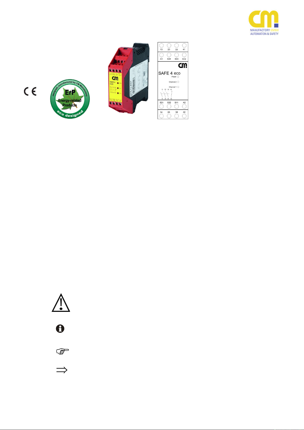
SAFE 4 eco
Original Bedienungsanleitung
Sicherheitsschaltgeräte für NotHalt-Kreise und Schutztürüberwachungskontakte
Original operating instructions
Abbildung ähnlich
Diese Bedienungsanleitung soll Sie mit
dem Not-Halt Sicherheitsrelais und
Schutztürwächter SAFE 4 eco / 4.1 eco /
4.2 eco / 4.3 eco vertraut machen
Diese Bedienungsanleitung gilt für alle
Geräte der Serie SAFE 4 eco (siehe
„Gerätevarianten“):
Die Bedienungsanleitung richtet sich an
folgende Personen:
Qualifizierte Fachkräfte, die Sicher-
heitseinrichtungen für Maschinen
und Anlagen planen und entwickeln
und mit den Vorschriften über Arbeitssicherheit und Unfallverhütung
vertraut sind.
Qualifizierte Fachkräfte, die Sicher-
heitseinrichtungen in Maschinen und
Anlagen einbauen und in Betrieb
nehmen.
Safety controller for e-stop and
safety gate monitoring applications
This operating instruction shall make
you familiar with the emergency stop
and safety gate monitoring relays
SAFE 4 eco /4.1 eco /4.2 eco /4.3 eco
This operation instruction is valid for all
devices of the SAFE 4 eco family (see
“Devices”)
The operating instruction is addressed
to the following persons:
Qualified professionals who plan
and develop safety equipment for
machines and plants and who are
familiar with the safety instructions
and safety regulations.
Qualified professionals, who install
safety equipment to machines and
plants and put them into operation.
Zeichenerklärung/
Explanation of signs
Dieses Symbol steht vor Textstellen, die
Dieses Symbol kennzeichnet Textstel-
Dieses Zeichen kennzeichnet auszufüh-
Nach diesem Zeichen wird beschrieben,
200803
1
In dieser Bedienungsanleitung werden
einige Symbole verwendet, um wichtige
Informationen hervorzuheben:
unbedingt zu beachten sind.
Nichtbeachtung
führt zur Verletzung
von Personen oder zu Sachschäden.
len, die wichtige Informationen enthalten.
rende Tätigkeiten.
wie sich der Zustand nach einer ausgeführten Tätigkeit ändert.
©
Copyright
gen, die dem technischen Fortschritt dienen, vor-
Alle Rechte vorbehalten. Änderun-
This operating instruction contains several symbols which are used to highlight important information:
This symbol is placed to indicate parts
of text which has to be absolutely paid
attention to. Nonobservance leads to
serious injuries or damage to property.
This symbol is placed to indicate parts
of text, which contains important information.
This sign is placed to indicate activities
After this sign follows a description on
how the situation has changed after an
activity is performed.
©
Copyright All
which serve technical improvements are re-
rights reserved. Changes,
Page 2
SAFE 4 eco
Bestimmungsgemäße
Verwendung /
Intended use
Varianten /
Variants
Personen - und Sachschutz sind nicht
Sicherheitshinweise
Die Sicherheitsrelais SAFE 4 eco /
4.1 eco / 4.2 eco / 4.3 eco sind bestimmt
für den Einsatz in:
Einkanalige und zweikanalige Schal-
tungstechnik für Not-Halt- oder
Schutztürüberwachungen
SAFE 4 eco mit Überwachung der
Starttaste
SAFE 4.1 eco ohne Überwachung
der Starttaste
SAFE 4.2 eco: wahlweise mit oder
ohne Überwachung der Starttaste
SAFE 4.3 eco: wahlweise mit oder
ohne Überwachung der Starttaste
und antivalenten Kontakten des
Auslöseelements
mehr gewährleistet, wenn das Sicherheitsrelais nicht entsprechend seiner bestimmungsgemäßen Verwendung eingesetzt wird.
Safety indications
The safety relay SAFE 4 eco / 4.1 eco
/ 4.2 eco / 4.3 eco is intended to be
used for:
Single and dual channel capabili-
ties for emergency stop or safety
gates applications
SAFE 4 eco with monitoring of the
start button
SAFE 4.1 eco without monitoring
of the start button
SAFE 4.2 eco: optionally with or
without monitoring of the start button
SAFE 4.3 eco: optionally with or
without monitoring of the start button and antivalent working contacts of the trigger element
Person and object-protection cannot
be fulfilled, if the safety relay isn’t used
by its intended use.
Beachten Sie unbedingt die folgenden
Punkte
Zu Ihrer Sicherheit
For your security
Das Gerät darf nur unter Beachtung
dieser Bedienungsanleitung von
Fachpersonal installiert und in Betrieb genommen werden, das mit
den geltenden Vorschriften über Arbeitssicherheit und Unfallverhütung
vertraut ist. Elektrische Arbeiten dürfen nur von Elektrofachkräften
durchgeführt werden.
Beachten Sie die jeweils gültigen
Vorschriften, insbesondere hinsichtlich der Schutzmaßnahmen.
Reparaturen, insbesondere das Öff-
nen des Gehäuses, dürfen nur vom
Hersteller oder einer von ihm beauftragten Person vorgenommen werden. Ansonsten erlischt jegliche Gewährleistung.
Vermeiden Sie mechanische Er-
schütterungen beim Transport oder
im Betrieb; Stöße größer 5g / 33Hz
(tbd) können zur Beschädigung des
Gerätes führen.
Montieren Sie das Gerät in einem
staub- und feuchtigkeitsgeschützten
Gehäuse IP54 oder besser; Staub
und Feuchtigkeit können zu Funktionsstörungen führen.
Sorgen Sie für eine ausreichende
Schutzbeschaltung bei kapazitiven
Please do pay attention to the the following points:
The device must only be installed
and operated by persons, who are
familiar with both, these instructions and the current regulations
for safety at work and accident
prevention. Electrical works must
only be executed by qualified electricians.
Follow local regulations as to pre-
ventative measures.
Any guarantee is void following
opening of the housing or unauthorized modifications.
Avoid mechanical vibrations
greater than 5 g / 33 Hz (tbd) when
transporting and in operation.
The unit has to be be panel
mounted in an enclosure rated at
IP 54 or better, otherwise dampness or just could lead to malfunction.
Adequate fuse protection must be
provided on all output contacts
200803
2
Page 3
SAFE 4 eco
und induktiven Lasten an den Ausgangskontakten.
In regelmäßigen Zeitabständen
muss das Sicherheitsrelais ausgelöst werden und auf korrekte Funktion geprüft werden (mindestens jedes halbe Jahr oder im Wartungszyklus der Anlage falls öfter).
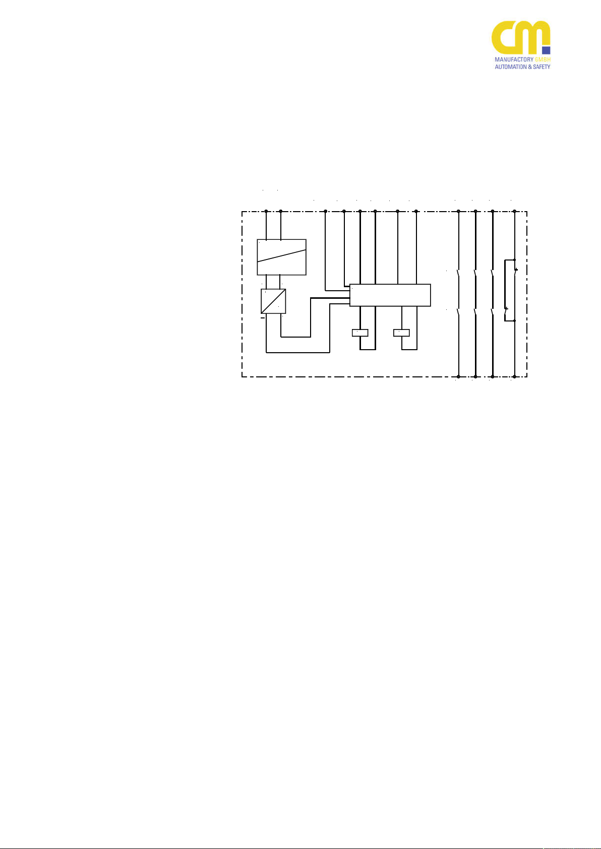
Aufbau und Funktionsweise /
Assembly and function
(function circuit diagram)
A1
(+)A2(-)
S33 S11
S34
elektr. Sicherung
electr. fuse
Transformator
transformer
~ ~
~
~
=
+
Überwachungslogik /
monitoring logic
13-14, 23-24, 33-34
41-42
S33-S34
S11-S12, S21-S22
Freigabestrompfade (Schließer,
zwangsgeführt)
Signalisierungsstrompfad (Öffner,
zwangsgeführt)
Start-Taster
Auslöseelement Kanal 1 und 2
Für das Betreiben des Gerätes muss
eine Hilfsspannung an die Klemmen A1
und A2 angelegt werden. Die LED
‘Power‘ leuchtet.
Die Anschlussklemmen S11, S12, S21
und S22 werden nach den entsprechenden Anwendungsbeispielen beschaltet.
Die Startapplikation wird entsprechend
den Anwendungsbeispielen (s.u.) angeschlossen.
In Reihe zu dem START-Taster kann
die Schaltung eines externen
Schützes überwacht werden
(siehe Anwendungsbeispiel).
Danach sind die Kontakte 13-14, 23-24,
33-34 geschlossen, der Kontakt 41-42
geöffnet. Die LEDs ‘Channel 1‘ und
‘Channel 2‘ leuchten.
with capacitive and inductive
loads.
The emergency stop relay has to
be tested in a time interval of every
six months or after each check of
the plant if more often.
S12
K1
S22S21
K2
13
K1
K2
14
3323 41
3424 42
safety circuits (normally open, forcibly
guided)
auxiliary circuits (normally close, forcibly guided)
start button
Trigger element channel 1 and 2
An supply voltage must be applied at
terminals A1 and A2. The ‘Power‘ LED
lights.
Terminals S11, S12, S21 and S22
have to be wired up as shown in the
application examples.
To start the unit, follow the examples
described in the start applications section.
In series to the start-button an
external contactor can be controlled
(see application example).
After activation the contacts 13-14, 2324 and 33-34 are closed, contact 4142 is opened.The LED’s ‘Channel 1‘
and ‘Channel 2‘ are lit.
200803
3
Page 4
SAFE 4 eco
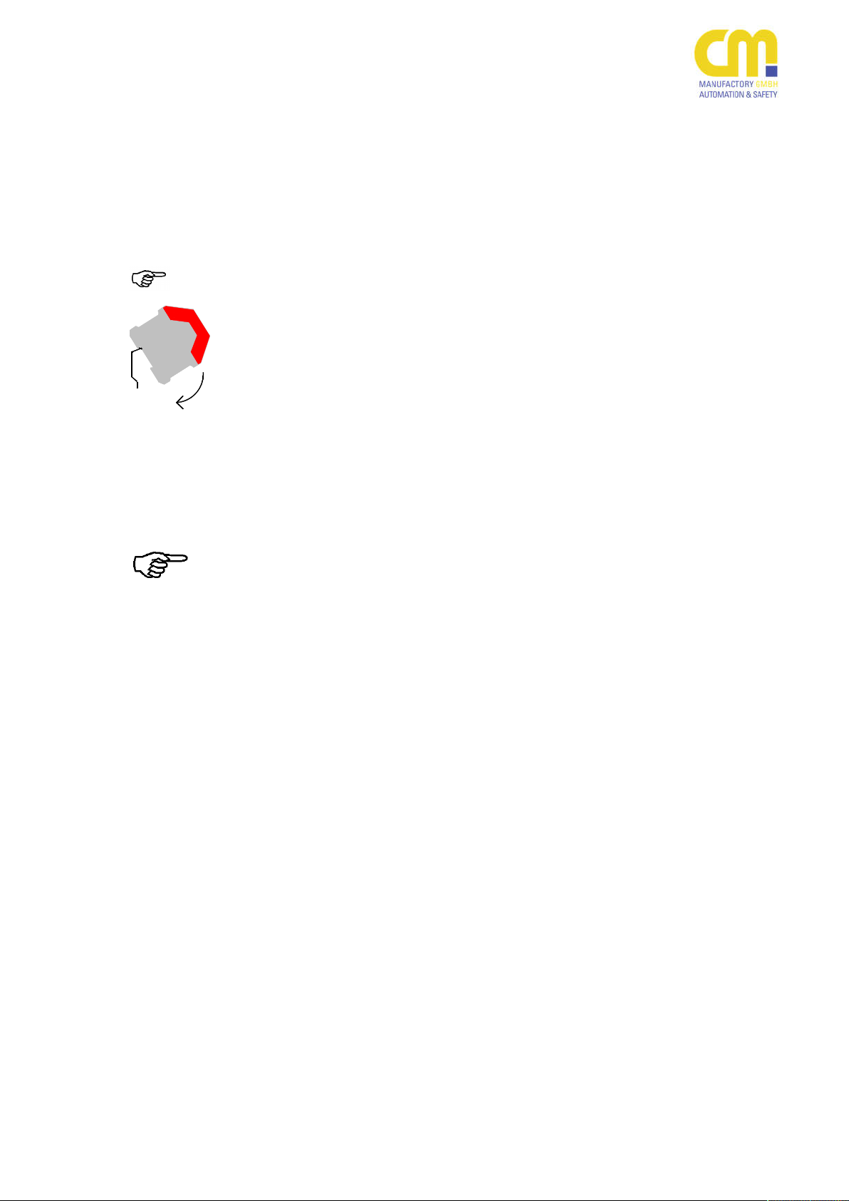
Mechanische
Montage mechanical
mounting
Montieren Sie das Sicherheitsrelais auf
Montage und Inbetriebnahme
Für eine sichere Funktion muss das Sicherheitsrelais in ein staub- und feuchtigkeitsgeschütztes Gehäuse eingebaut
werden (IP54).
eine Norm-Hutschiene.
Hinweis: Die Norm-Hutschiene muss geerdet
sein (EN 60947-5-1)!
Elektrischer
Anschluss
Electronic
connection
Führen Sie die Verdrahtung entsprechend des Verwendungszweckes durch.
Orientieren Sie sich dabei an den Anwendungsbeispielen. Generell ist das
Sicherheitsrelais nach folgenden Angaben zu verdrahten:
Bevor Sie mit der Verdrahtung beginnen, beachten Sie bitte unbedingt die
folgenden Hinweise:
Kombinieren Sie die folgenden
Teilschaltbilder. Ausführliche
Schaltungsbeispiele finden Sie
bei den Anwendungsbeispielen.
Bei 115VAC- und 230VAC-Vari-
anten muss der Erdanschluss
an die Klemme S21 angeschlossen werden.
Beachten Sie die maximalen
Leitungslängen (siehe Technische Daten).
Mounting and commissioning
The unit must be panel mounted in an
enclosure protected against dust and
humidity rated at IP 54 or better.
There is a notch on the rear of the unit
for DIN-Rail attachment.
Hint: The DIN-Rail has to be grounded
(EN 60947-5-1)!
Carry out the wiring appropriate to the
intended use according to the examples of application.
Generally the safety-relay has to be
wired under following specifications:
Before to start wiring please consider
the following hints:
Combine the following sub-dia-
115VAC and 230VAC types:
Please take notice of the maxi-
grams. Complete diagrams
please find in the examples
section.
the protective ground has to
be applied to terminal S21.
mum wire lengths (see technical data).
200803
4
Page 5
SAFE 4 eco
Elektrischer Anschluss
Electrical Wiring
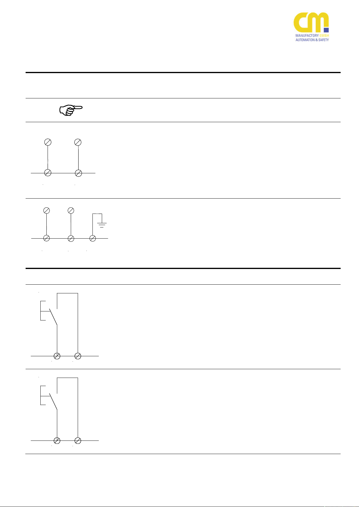
Anschluss Spannungsversor-
gung
A1
A2
A1
A2
S21
Start
S33
S34
Start
S33
S34
Beachten Sie hierzu die Angabe auf
dem Typenschild des Geräts
Alle 24V Varianten (AC und DC):
Der Anschluss der Spannungsversorgung erfolgt an den Klemmen A1 und
A2. Für die Versorgung mit DC ist die
Polarität nicht relevant.
Bitte beachten Sie, dass der Erdanschluss (PE) an der Klemme S21 nicht
angeschlossen werden darf!
Alle 115VAC- und 230VAC-Varianten:
Der Anschluss der Spannungsversorgung erfolgt an den Klemmen A1 und
A2.
Bitte beachten Sie, dass der Erdanschluss (PE) an die Klemme S21 angeschlossen werden muss!
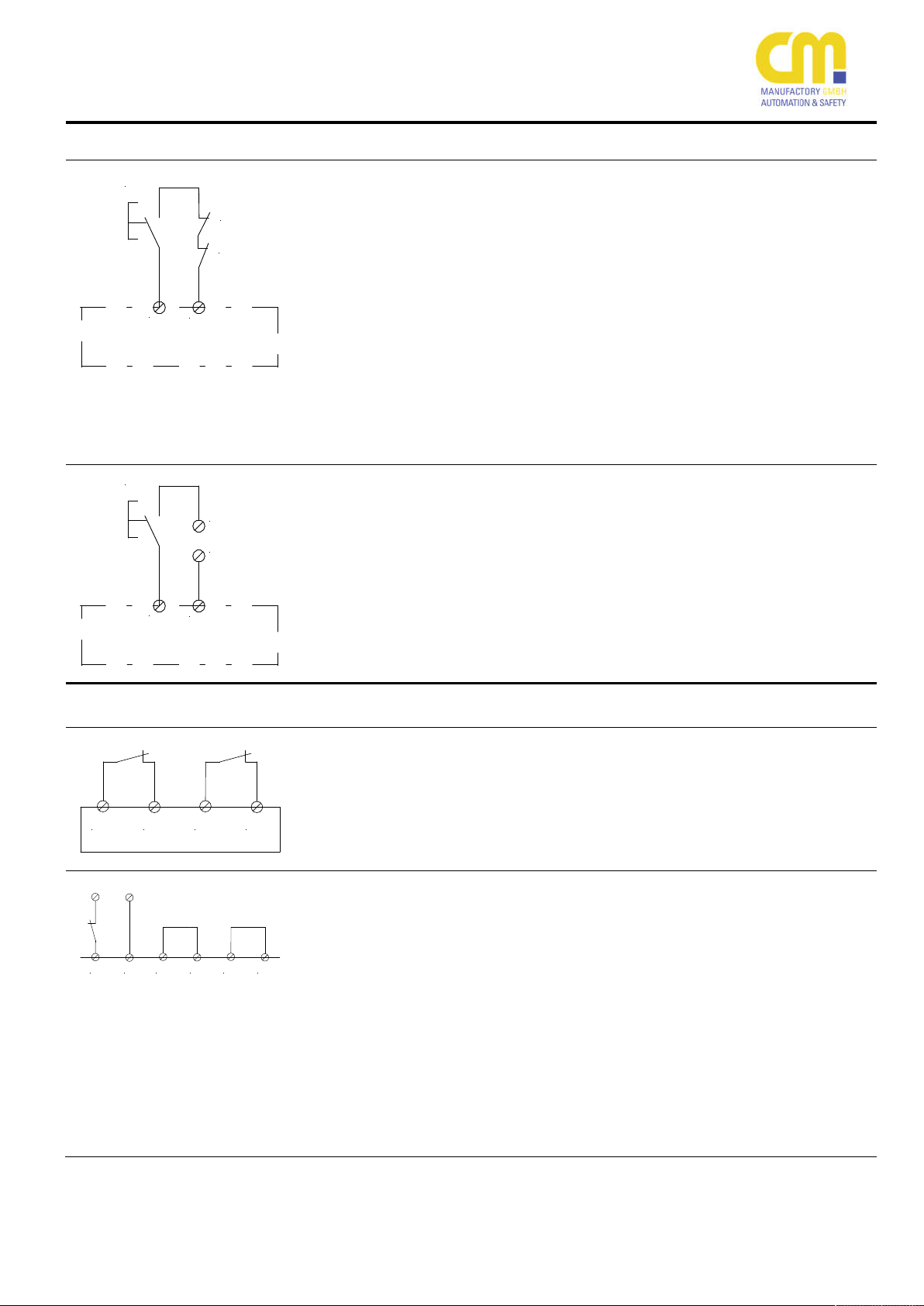
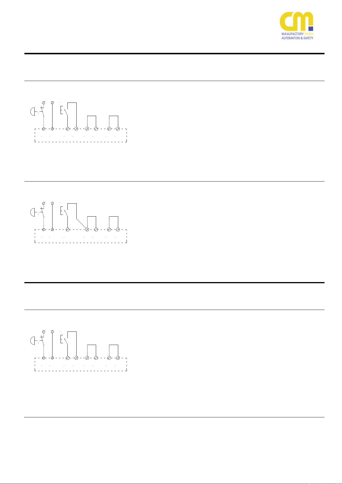
Startapplikationen
SAFE 4 eco:
Start mit Überwachung des Starttasters;
das Gerät reagiert auf das Öffnen des
Tasterkontakts (mit dem Schließen der
Freigabestromkreise).
Anmerkung: In den Startkreis können
Loopbacks von externen Schützen oder
Kontakterweiterungen (SAFE X4) eingebaut werden, siehe Applikationsbeispiele
SAFE 4.1 eco:
Start ohne Überwachung des Starttasters, das Gerät reagiert auf das
Schließen des Tasterkontakts (mit dem
Schließen der Freigabestromkreise).
Anmerkung: In den Startkreis können
Loopbacks von externen Schützen oder
Kontakterweiterungen (SAFE X4) eingebaut werden, siehe Applikationsbeispiele
Wiring of the power supply
Please refer to the information on
the nameplate of the device
All 24V variants (AC and DC):
The connection of the power supply is
carried out on the terminals A1 and A2.
If the device is powered by DC, the polarity is irrelevant.
Please notice that S21 must not be
wired with protection earth (PE)!
All 115VAC and 230VAC variants:
The connection of the power supply is
carried out on the terminals A1 and A2.
Please notice to carry out S21 with
protection earth (PE)!
Start (Reset) Applications
SAFE 4 eco:
Start (Reset) with monitoring of the
start button. The device will be activated (the safety circuits close) after
the start button contact is opened.
Note: Loopbacks of external contactors
or contact expansions (SAFE X4) can
be looped into the start circuit, please
see application examples.
SAFE 4.1 eco:
Start (Reset) without monitoring of the
start button. The device will be activated (the safety circuits close) after
the start button contact is closed.
Note: Loopbacks of external contactors
or contact expansions (SAFE X4) can
be looped into the start circuit, please
see application examples.
200803
5
Page 6

SAFE 4 eco
Start
S34
S21
Start
S33
S33
S33
S11
S34
S11
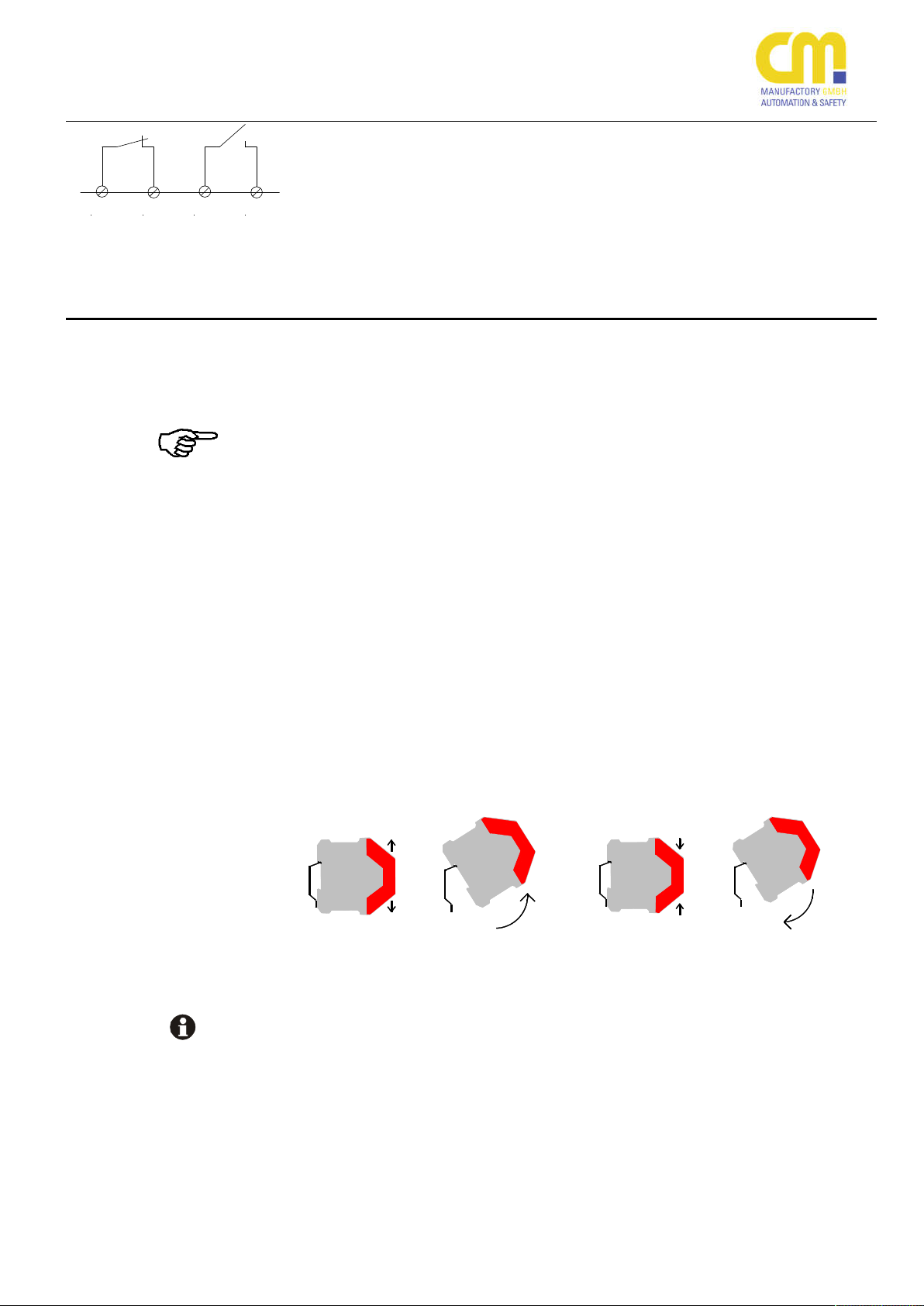
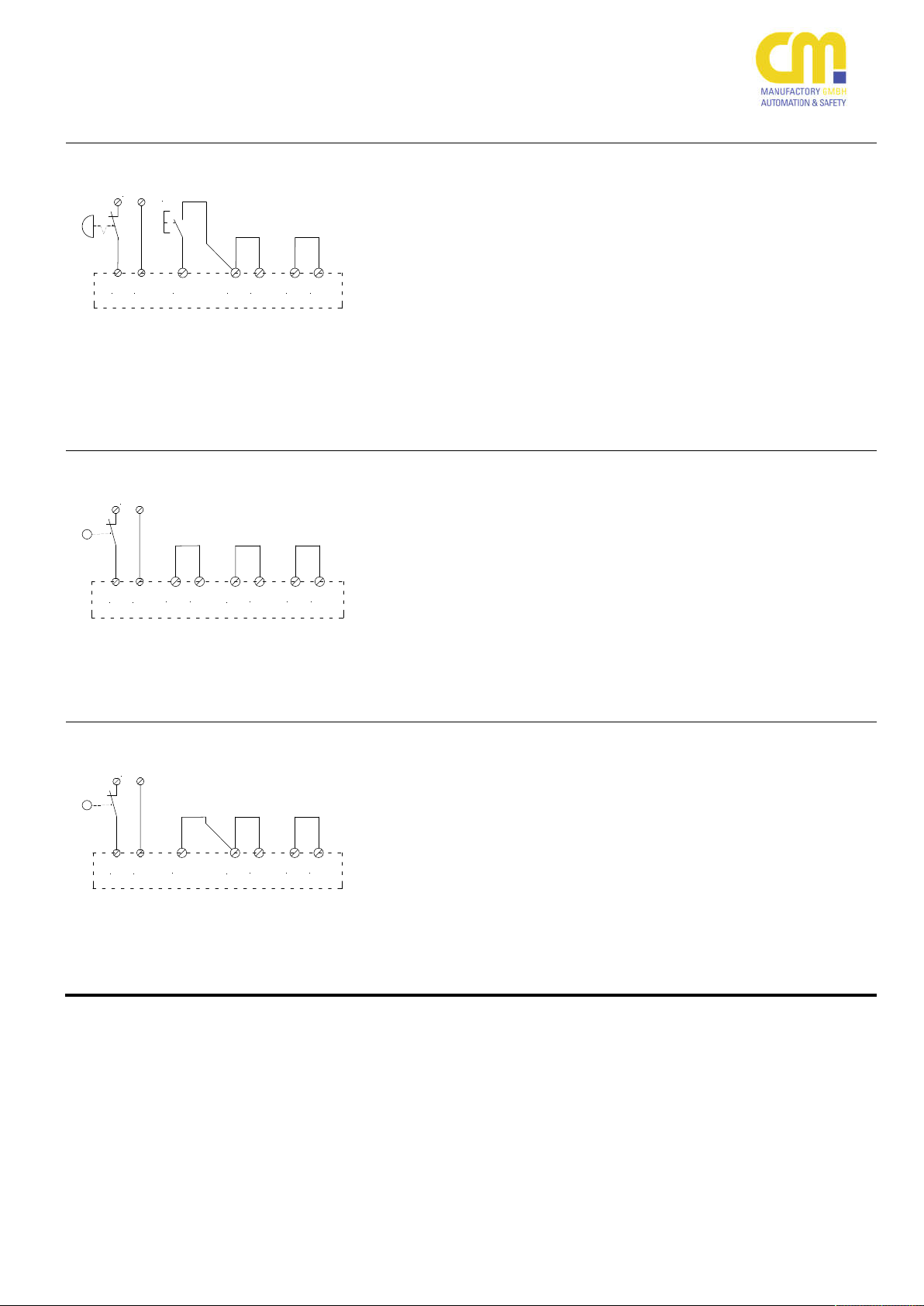
SAFE 4.2 eco:
SAFE 4.3 eco:
Start mit Überwachung des Starttasters;
das Gerät reagiert auf Öffnen des Tasters (mit dem Schließen der Freigabestromkreise).
Anmerkung: In den Startkreis können
Loopbacks von externen Schützen oder
Kontakterweiterungen (SAFE X4) eingebaut werden, siehe Applikationsbeispiele
SAFE 4.2 eco:
SAFE 4.3 eco:
Start ohne Überwachung des Starttasters; das Gerät reagiert auf Schließen
des Tasters (mit dem Schließen der
Freigabestromkreise).
Anmerkung: In den Startkreis können
Loopbacks von externen Schützen oder
Kontakterweiterungen (SAFE X4) eingebaut werden, siehe Applikationsbeispiele
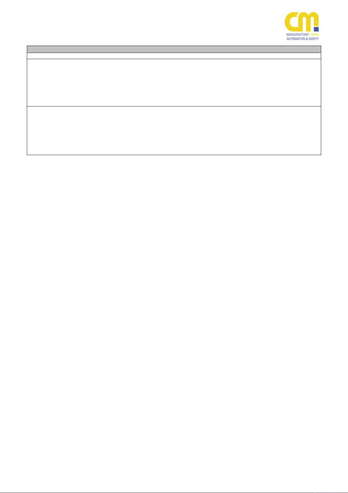
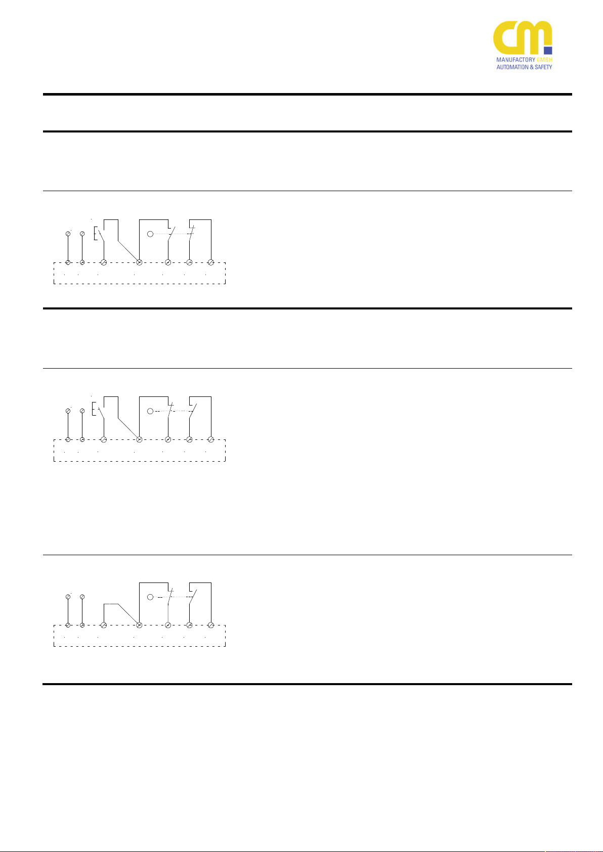
SAFE 4.1 eco:
Automatischer Start.
Die Freigabestromkreise werden geschlossen, sobald die Kontakte der Auslöseelemente geschlossen sind.
Bitte beachten Sie, dass diese Funktionalität für Nothalt-Applikationen
nicht zugelassen ist!
Anmerkung: Anstelle der Brücke können
Loopbacks von externen Schützen oder
Kontakterweiterungen (SAFE X4) angeschlossen werden, siehe Applikationsbeispiele
SAFE 4.2 eco:
SAFE 4.3 eco:
Automatischer Start.
Die Freigabestromkreise werden geschlossen, sobald die Kontakte der Auslöseelemente geschlossen sind.
Bitte beachten Sie, dass diese Funktionalität für Nothalt-Applikationen
nicht zugelassen ist!
Anmerkung: In den Startkreis können
Loopbacks von externen Schützen oder
Kontakterweiterungen (SAFE X4) eingebaut werden, siehe Applikationsbeispiele
SAFE 4.2 eco:
SAFE 4.3 eco:
Start (Reset) with monitoring of the
start button. The device will be activated (the safety circuits close) after
the start button contact is opened.
Note: Loopbacks of external contactors
or contact expansions (SAFE X4) can
be looped into the start circuit, please
see application examples
SAFE 4.2 eco:
SAFE 4.3 eco:
Start (Reset) without monitoring of the
start button. The device will be activated (the safety circuits close) after
the start button contact is closed.
Note: Loopbacks of external contactors
or contact expansions (SAFE X4) can
be looped into the start circuit, please
see application examples
SAFE 4.1 eco:
Automatic start
The device will be activated (the safety
circuits close) after the trigger element
contacts are closed.
Please note this functionality ispermitted for e-stop applications!
Note: In spite of the bridge external
contactors or contact expansions
(SAFE X4) can be looped into the start
circuit, please see application examples
SAFE 4.2 eco:
SAFE 4.3 eco:
Automatic start
The device will be activated (the safety
circuits close) after the trigger element
contacts are closed.
Please note, this functionality is
permitted for e-stop applications!
Note: Loopbacks of external contactors
or contact expansions (SAFE X4) can
be looped into the start circuit, please
see application examples
200803
6
Page 7
SAFE 4 eco
Kontakterweiterung in den Startkreis
expansion within the start circuit
Start
K1ext
K2ext
S33
S34
Start
Y1
Y2
S34
S21
Beispiel für die Überwachung einer
SAFE 4 eco:
Start mit Überwachung des Starttasters;
das Gerät reagiert auf Öffnen des Tasterkontakts (Schließen der Freigabestromkreise).
SAFE 4.1 eco:
Start ohne Überwachung des Starttasters, das Gerät reagiert auf das Schlie-
ßen des Tasterkontakts (Schließen der
Freigabestromkreise).
Anmerkung: In den Startkreis sind Kontakte für eine externe Schützüberwachung eingebaut, siehe auch Applikationsbeispiele
SAFE 4.2 eco:
SAFE 4.3 eco:
Start mit Überwachung des Starttasters;
das Gerät reagiert auf Öffnen des Tasterkontakts (Schließen der Freigabestromkreise).
Anmerkung: In den Startkreis sind Kontakte für eine Kontakterweiterung
SAFE X4 (Y1-Y2) eingebaut, siehe auch
Applikationsbeispiele.
Example for Monitoring of a contact
SAFE 4 eco:
Start (Reset) with monitoring of the
start button. The device will be activated (the safety circuits close) after
the start button contact is opened.
SAFE 4.1 eco:
Start (Reset) without monitoring of the
start button. The device will be activated (the safety circuits close) after
the start button contact is closed.
Note: There are Loopbacks of external
contactors or contact expansions
(SAFE X4) looped into the start circuit,
please see application examples
SAFE 4.2 eco:
SAFE 4.3 eco:
Start (Reset) with monitoring of the
start button. The device will be activated (the safety circuits close) after
the start button contact is opened.
Note: There is the safe loopback of the
external contact expansion SAFE X4
looped into the start circuit, please see
application samples.
S11 S12 S21 S22
S11 S12 S21 S22A1 A2
Auslöse-Applikationen
SAFE 4 eco:
SAFE 4.1 eco:
SAFE 4.2 eco:
Das ist die zweikanalige Standard-Anwendung mit Querschlusserkennung,
die Nothaltschalter, bzw. die Schutztürschalter sind entsprechend verdrahtet.
SAFE 4.1 eco:
SAFE 4.2 eco:
Das ist eine einkanalige Anwendung
mit wahlweise einem Nothalt- oder einem Schutztürschalter.
Bei Verlegung der Anschlussleitungen in
getrennten Mantelleitungen kann eine
Kategorie 4 erreicht werden (Ausschluss
eines Querschlussfehlers).
Bitte beachten Sie, dass die Abschaltzeiten sich verlängern:
24V: 180 ms
115V / 230V: 130 ms
Trigger Applications
SAFE 4 eco:
SAFE 4.1 eco:
SAFE 4.2 eco:
This is the dual channel standard application with cross circuit monitor-
ing. The e-stop elements or the safety
gate elements are wired accordingly.
SAFE 4.1 eco:
SAFE 4.2 eco:
This is a single channel application
with either one e-stop or safety gate
contact.
A category 4 can be reached if the wiring of the trigger elements are installed
seperately in sheathed cables to reach
an exclusion of cross circuits.
Please notice, that the release times
increase significantly:
24V: 180 ms
115V / 230V: 130 ms
200803
7
Page 8
SAFE 4 eco
Maintenance and Repair
S11 S12 S21 S22
Wartung und Reparatur
SAFE 4.3 eco
Das ist die zweikanalige Standardanwendung mit Querschlusserkennung
für antivalente Schutztürschalter. Der
Öffner wird an das Kontaktpaar S11-S12
angeschlossen und der Schließer an
S21-S22.
Diese Schalterstellung steht für eine ge-
schlossene Tür
Wartung Maintenance
Das Gerät arbeitet wartungsfrei.
Entsprechend den Sicherheitsanforderungen muss das Gerät mindestens alle
6 Monate einen Schaltzyklus durchlaufen. D.h. dass die Sicherheitsfunktion
nach spätestens 6 Monaten einmal auslösen muss.
Austausch des Geräts
Zum Austausch des Gerätes empfehlen
wir die Kabel eins zu eins abzuschrauben und an das Austauschgerät anzuschrauben.
1. Kabel abschrauben und an das Austauschgerät anschrauben.
2. Defektes Gerät von der Hutschiene
nehmen.
3. Austauschgerät auf Hutschiene
montieren.
SAFE 4.3 eco
This is the dual channel standard application with cross circuit monitor-
ing for antivalent switching safety
gate element contacts. The e-stop elements or the safety gate elements are
wired accordingly.
This position means: the safety gate is
closed.
The device is free of maintenance.
According to the safety standards the
device has to run a complete switching
cycle at least each 6 months. Means,
the safety functions have to be released every 6 months.
Exchange of the device
To exchange the device we recommend to disconnect the cables and
connect them to the other device one
by one.
1. Disconnect the cables and connect
them with the replacement device.
2. Dismount the defect device from
the rail
3. Mount the replacement device on
the rail
Erdschluss bei AC-DCVariante (mit elektr.
Sicherung)
Earth fault at AC/DC variant
(with electr. fuse)
200803
8
Fehler, Störungen, Auswirkungen,
Maßnahmen
Führen Sie keine Reparaturversuche
durch. Sollte sich das Gerät als defekt
herausstellen, schicken Sie das Gerät
an CM Manufactory GmbH ein.
Die Sicherung löst aus, die Freigabestromkreise öffnen.
→ Nach Wegfall der Störungsursache
ist das Gerät wieder betriebsbereit.
Faults, Disturbances, Effects and
Measures
Do not attempt to repair the unit yourself. In case of failure or malfunction of
the device send it back to CM Manufactory GmbH.
If the fuse releases, the safety circuits
open.
→ If the problem is solved, the device
will be ready for operation again.
Page 9

SAFE 4 eco
Fehlfunktion der Kontakte
Malfunction of the contacts
LED „Power“ leuchtet nicht.
LED „power“ is not lit
Nur eine LED (Channel1
oder Channel2) leuchtet
Only one LED (channel 1 or
channel 2) is lit
Bei verschweißten Kontakten ist nach
dem Öffnen der Ausgangskreise keine
neue Aktivierung möglich.
→ In diesem Fall das Gerät an CM Ma-
nufactory GmbH einschicken.
Versorgungsspannung ist nicht angeschlossen.
→ Versorgungsspannung wie oben be-
schrieben anschließen.
Externer Kurzschluss vorhanden (z.B.
S11 gegen Masse).
→ Verdrahtung überprüfen
Der Ausschaltimpuls war zu kurz. Das
Gerät schaltet die Freigabestromkreise
nicht mehr durch.
→ Das Auslöseelement länger betäti-
gen oder das Netz ab und wieder
einschalten (RESET).
Nur ein Kanal des Auslöseelements öffnet
→ Auslöseelement prüfen und ggf. er-
setzen.
Ein Verdrahtungsfehler liegt vor.
→ Verdrahtung der Kanäle überprüfen.
In the case the safety circuit contacts
are welded, the device will refuse a
new activation after the safety circuits
have been opened.
→ In this case please send the device
back to CM Manufactory GmbH.
Power supply not mounted
→ mount power supply as described
above
External cross circuit (for example S11
against ground)
→ check wiring
The release pulse was too short. The
device does not close the safety circuits any longer.
→ release the trigger element longer
or switch off and on the device
(RESET)
Only one channel of the trigger element opens
→ check trigger element and ex-
change it if necessary
There is a wiring fault
→ check the wiring of the channels
200803
9
Page 10

SAFE 4 eco
Gerätetyp / Type of device
SAFE 4 eco, SAFE 4.1 eco, SAFE 4.2 eco, SAFE 4.3 eco
230V AC / 115V AC.
Spannungsbereich / voltage range
115VAC, 230VAC: ±10% 103,5..127 VAC / 207..253 VAC
Frequenz (AC-Variante) / frequency (AC-type)
48 ... 63 Hz
SAFE 4.3 eco: <10 mA
115VAC: 3,6 VA
Leitungsdaten / Conductor data
UL: Use Copper Conductors Only!
max. conductor length (input circuit)
4 x 100m ( zweikanalig / dual channel)
Leiterquerschnitt / conductor cross-section
2 x 1,5 mm2 / 4 x 1,5mm²
Kapazität / capacity
150 nF/km
Temperatur / temperature
+ 25°C
Kontaktdaten / Contact data
3 normally open (NO) / 1 auxiliary normally closed (NC)
Kontaktart / contact type
Relais zwangsgeführt / relay forcibly guided
Kontaktmaterial / contact material
Kontaktwerkstoff AgNi, hauchvergoldet / Gold-flashed AgNi alloy type
Schaltspannung / switching voltage
240V AC, 24V DC
Umgebungstemp. / ambient temperature: 70°C
Schaltstrom min. / min. switching current
10mA (10VDC)
Schaltleistung max. / max. switching capacity
1200 VA (ohmsche Last) / 1200 VA (ohms load)
Mechanische Lenbensdauer / mechanical lifetime
107 Schaltspiele / switches
Elektrische Lebensdauer / electrical lifetime
105 Schaltspiele / switches (AC1, DC1 jeweils / each 5A)
clearance
basic isolation: over voltage category 3 / 250 V
4 kV
Öffner: 4A Neozed gL/gG / NC contact: 4A Neozed gL/gG
Sicherungseinsatz Typ (Größe D01) / Fuse link type (size D01) : 6 gG
inputs)
Rückfallverzögerung / delay on deenergisation
≤ 15 ms (zweikanalig / dual channel)
Gehäusematerial / housing material
Polyamid PA 6.6
Abmessungen (BxHxT) in mm / dimensions ( bxhxd )
22,5 x 114,5 x 99
click-fastening for grounded DIN-Rail
Luftfeuchtigkeit / humidity
Wechselklima / alternating climate 95% 0-50°C
Anschlussart / type of mounting
Schraubklemmen / screw terminals
connection terminals
(UL: „Tighten to 0.5-0.6 N.m. Overtorquing may cause enclosure breakage“)
Gewicht mit Klemmen / weight with terminals
max. 160g (nur 24VACDC)
Lagerung / storage
In trockenen Räumen / in dry areas
Lager: -25°C ... +70°C
Schutzart Klemmen / terminal type
IP 20
Schutzart Gehäuse / housing type
IP 40
contacts
8g / 2g
Technische Daten / Technical Data
Allgemeine Daten / General Data
Elektrische Daten / Electrical data
Versorgungsspannung Uv / supply voltage
Bemesssungsbetriebsspg / rated operational voltage
Strom über Auslöselement / current via trigger element SAFE 4 eco, SAFE 4.1 eco, SAFE 4.2 eco: <32 mA
24V AC/DC
24V AC/DC: -15% ...+20% 20,4..28,8VAC/DC
Leistungsaufnahme ca. (Freigabestromkreise geschlossen)
/
power consumption appr. (output contacts activated)
Leiteranschluß / conductor connection 2 x 1,5 mm2 Massivdraht (Cu) / massive wire
Max. Leitungslängen (Eingangskreis) /
Kontaktbestückung / contact-allocation 3 Schließer / 1 Öffner
Schaltstrom / switching current
für freistehende Geräte / free-standing devices
Gebrauchskategorien / utilization categories
Kriech- und Luftstrecken / creeping distance and
24V DC: 1,7 W
24V AC: 2 VA
230VAC: 3,6 VA
2 x 1,5 mm2 Litze (Cu) mit Hülse /
2 x 100m ( einkanalig / single channel)
6A (nur 24VDC-Betrieb / 24 VDC operation mode only);
5A (alle anderen Betriebsarten / all other operation modes)
AC1: 5A; DC1: 5A
jeweils / each: cos φ=1; Lastzyklen / duty cycle 20% 1s EIN, 4s AUS / 1s ON, 4s OFF
-VDE 0160 für Verschmutzungsgrad 2,
Überspannungskategorie 3 / 250 V
VDE 0160 at pollution grade 2,
over voltage category 3 / 250 V
-Basisisolierung: Überspannungskategorie 3 / 250 V
strand with hull
Bemessungsisolationsspannung / rated insulation voltage
Bemessungsstoßspannungsfestigkeit / rated impulse strength
Kontaktabsicherung / contact security Schließer: 6,3A flink / NO contact: 6,3A brisk
Kurzschlussfestigkeit / Short Circuit Withstand 1kA
Wiederbereitschaftszeit (minimale Abschaltzeit der
Eingänge) / recovery time (minimum switch off time of the
Mechanische Daten / Mechanical data
Befestigung / fastening Schnappbefestigung für geerdete Normhutschiene /
Anzugsmoment für Anschlussklemmen / Torque setting for
Umgebungsdaten / Environmental data
Umgebungstemperatur / operating temperature
Stoßfestigkeit Schließer/Öffner / shock resistance NO/NC
200803
10
250V (eff)
0,5 s
min. 0,5 Nm / max. 0,6 Nm
Betrieb: -25°C ... +55°C (UL: ..40°C)
Page 11
SAFE 4 eco
Zertifizierungen und Daten / Certifications and Data
Zulassungen / Certifications TÜV, UL/CUL
Prüfungen gemäß EN ISO 13849-1
Tests according to EN ISO 13849-1
Ergänzende Informationen gemäß EN 62061 und EN 61508:
Supplementary details according to EN 62061 und EN 61508:
MTTFD in Jahren / years
Elektronik/Electronic: 2500
Gesamt/Total : 910 mit/with B
Gesamt/Total : 300 mit/with B
Gesamt/Total: 36 mit/with B
DC = 99%
Kategorie / category 4
Performance Level e
PFH / PFHD in 1/h
Elektronik/Electronic: 9,78∙10
Gesamt/Total : 2,32∙10-9 mit/with B
Gesamt/Total : 7,35∙10-9 mit/with B
Gesamt/Total: 7,41∙10-9 mit/with B
SFF > 99%
HFT = 1
SIL3
=400.000, hop=24, dop=365, t
10D
=400.000, hop=24, dop=365, t
10D
=400.000, hop=24, dop=365, t
10D
-13
=400.000, hop=24, dop=365, t
10D
=400.000, hop=24, dop=365, t
10D
=400.000, hop=24, dop=365, t
10D
Zyklus/cycle
Zyklus/cycle
Zyklus/cycle
Zyklus/cycle
Zyklus/cycle
Zyklus/cycle
=1800
=600
=60
=1800
=600
=60
200803
11
Page 12

SAFE 4 eco
Applikationen /
Applications
Start
U
B
S33
S34
Start
S34
A1 A2
U
A1 A2
B
S11 S12
S22 S11 S12
S21
S21 S22
Anwendungsbeispiele
Die Anwendungsbeispiele sind im
Wesentlichen nach Aufgabenstellungen geordnet. Lediglich für das
SAFE 4.3 eco wurde ein eigener
Bereich reserviert. Am Ende des
Kapitels findet sich noch ein Absatz
über die korrekte Verdrahtung von
Kontakterweiterungen.
Bitte beachten Sie, dass be
115VAC- und 230VAC-Varianten
der Erdanschluß (PE) an die
Klemme S21 angeschlossen werden muss.
Zweikanalige Nothalt-Überwachung mit Querschlusssicherheit
und überwachtem Start
SAFE 4 eco:
Mit dem Öffnen des Starttastenkontakts schließen die Freigabestromkreise.
In den Startkreis (S33-S34) können
die Überwachungskontakte einer
externen Kontakterweiterung eingebaut werden (siehe „Externe Kontakterweiterung“).
Max. erreichbar: Kat. 4, SIL3, PLe
SAFE 4.2 eco
Mit dem Öffnen des Starttastenkontakts schließen die Freigabestromkreise.
In den Startkreis (S34-S21) können die Überwachungskontakte einer externen Kontakterweiterung
eingebaut werden (siehe „Externe
Kontakterweiterung“).
Max. erreichbar: Kat. 4, SIL3, PLe
Application examples
The application examples are
sorted by tasks. Only for the
SAFE 4.3 eco a new section has
been created. In the end of this
please find an example how to
mount an contact expansion correctly.
Please take notice, that the protective ground (PE) has to be applied to terminal S21.
Dual channel e-stop monitoring
with cross circuit monitoring
and monitored start button
SAFE 4 eco:
After the start button contacts
open the safety circuits close.
Loopbacks of external contactors
or contact expansions (SAFE X4)
can be looped into the start circuit
(S33-S34), please see “contact
expansion”.
Max. achievable: cat. 4, SIL3, PLe
SAFE 4.2 eco
After the start button contacts
open the safety circuits close.
Loopbacks of external contactors
or contact expansions (SAFE X4)
can be looped into the start circuit
(S21-S34), please see “contact
expansion”.
Max. achievable: cat. 4, SIL3, PLe
200803
12
Page 13

SAFE 4 eco
ton
button
Zweikanalige Schutztür-Überwachung mit Querschlusssicherheit
und überwachtem Start.
Dual channel safety gate monitoring with cross circuit monitoring and monitored start but-
Start
B
U
SAFE 4 eco
Mit dem Öffnen des Starttastenkontakts schließen die Freigabestromkreise.
A1 A2
S33
S34
S11
S12 S21 S22
In den Startkreis (S33-S34) können
die Überwachungskontakte einer
externen Kontakterweiterung eingebaut werden (siehe „Externe Kontakterweiterung“).
SAFE 4 eco
After the start button contacts
open the safety circuits close.
Loopbacks of external contactors
or contact expansions (SAFE X4)
can be looped into the start circuit
(S33-S34), please see “contact
expansion”.
Max. achievable: cat. 4, SIL3, PLe
Max. erreichbar: Kat. 4, SIL3, PLe
Start
B
U
SAFE 4.2 eco
Mit dem Öffnen des Starttastenkontakts schließen die Freigabestromkreise.
A1 A2
S34
S21
S22 S11 S12
In den Startkreis (S34-S21) können die Überwachungskontakte einer externen Kontakterweiterung
eingebaut werden (siehe „Externe
Kontakterweiterung“).
SAFE 4.2 eco
After the start button contacts
open the safety circuits close.
Loopbacks of external contactors
or contact expansions (SAFE X4)
can be looped into the start circuit
(S21-S34), please see “contact
expansion”.
Max. achievable: cat. 4, SIL3, PLe
Max. erreichbar: Kat. 4, SIL3, PLe
Zweikanalige Schutztür-Überwachung mit Querschlusssicherheit
und nicht überwachtem Start.
Start
B
U
SAFE 4.1 eco
Mit dem Schließen des Starttastenkontakts schließen die Freigabestromkreise.
A1 A2
S33
S34
S11
S12 S21 S22
In den Startkreis (S33-S34) können
die Überwachungskontakte einer
externen Kontakterweiterung eingebaut werden (siehe „Externe Kontakterweiterung“).
Hinweis: Diese Startart ist nicht für
Nothalt-Anwendungen zugelassen
(nur Taster sind zugelassen).
Max. erreichbar: Kat. 4, SIL3, PLe
Dual channel safety gate monitoring with cross circuit monitoring and not monitored start
SAFE 4.1 eco
After the start button contacts
close the safety circuits close.
Loopbacks of external contactors
or contact expansions (SAFE X4)
can be looped into the start circuit
(S33-S34), please see “contact
expansion”.
Hint: This start type is not valid
for e-stop applications (only push
buttons are valid).
Max. achievable: cat. 4, SIL3, PLe
200803
13
Page 14

SAFE 4 eco
Start
B
U
SAFE 4.2 eco
Mit dem Schließen des Starttastenkontakts schließen die Freigabestromkreise.
A1 A2
S33
S11
S12 S21 S22
In den Startkreis (S33-S11) können
die Überwachungskontakte einer
externen Kontakterweiterung eingebaut werden (siehe „Externe Kontakterweiterung“).
Hinweis: Diese Startart ist auch für
Nothalt-Anwendungen zugelassen.
Max. erreichbar: Kat. 4, SIL3, PLe
B
U
SAFE 4.1 eco
Die Freigabestromkreise schließen
sobald die Kontakte des Auslöseelements geschlossen sind.
A1 A2
S11
S12
S21 S22S33 S34
In den Startkreis (S33-S34) können
die Überwachungskontakte einer
externen Kontakterweiterung eingebaut werden (siehe „Externe Kontakterweiterung“).
Hinweis: Diese Startart ist für Nothalt-Anwendungen nicht zugelassen.
SAFE 4.2 eco
After the start button contacts
close the safety circuits close.
Loopbacks of external contactors
or contact expansions (SAFE X4)
can be looped into the start circuit
(S33-S11), please see “contact
expansion”.
Hint: This start type is also valid
for e-stop applications.
Max. achievable: cat. 4, SIL3, PLe
SAFE 4.1 eco
After the trigger element contacts
close the safety circuits close.
Loopbacks of external contactors
or contact expansions (SAFE X4)
can be looped into the start circuit
(S33-S34), please see “contact
expansion”.
Hint: This start type is not valid
for e-stop applications.
Max. achievable: cat. 4, SIL3, PLe
Max. erreichbar: Kat. 4, SIL3, PLe
B
U
SAFE 4.2 eco
Automatischer Start:
Die Freigabestromkreise schließen,
sobald die Kontakte des Auslösee-
A1 A2
S33
S11 S12
S21 S22
lements geschlossen sind.
In den Startkreis (S33-S11) können
die Überwachungskontakte einer
externen Kontakterweiterung eingebaut werden (siehe „Externe Kontakterweiterung“).
Hinweis: Diese Startart ist für Nothalt-Anwendungen nicht zugelassen.
SAFE 4.2 eco
Automatic start:
After the trigger element contacts
close the safety circuits close.
Loopbacks of external contactors
or contact expansions (SAFE X4)
can be looped into the start circuit
(S33-S11), please see “contact
expansion”.
Hint: This start type is not valid
for e-stop applications.
Max. achievable: cat. 4, SIL3, PLe
Max. erreichbar: Kat. 4, SIL3, PLe
200803
14
Page 15
SAFE 4 eco
Einkanalige Nothalt- und Schutztür-Überwachung mit überwachtem Start
U
B
Start
SAFE 4 eco
Die Freigabestromkreise schließen
bei geschlossenem Auslöseelementkontakt und dem Schließen
der Starttaste
A1 A2
S33
S34
S12 S21 S22
S11
Diese Schaltung gilt entsprechend
für Schutztüranwendungen.
Max. erreichbar: Kat. 4, SIL3, PLd
(Diese Kennwerte sind nur erreichbar bei
Verwendung von zwangstrennenden Schaltern und Verlegung der Kabel in getrennten
Mantelleitungen!)
Single channel e-stop and
safety gate monitoring with
monitored start button
SAFE 4 eco
The safety circuits close if trigger
element contact is closed and the
start button is closed.
This wiring is also valid for safety
gate applications
Max. achievable: cat. 4, SIL3, PLd
(These Parameters are only ahievable
when using restricted guided switches and
the wiring is lead in separated coated cables.)
U
B
Start
SAFE 4.2 eco
Die Freigabestromkreise schließen
bei geschlossenem Kontakt des
Auslöseelements und dem Schließen der Starttaste
A1 A2
S33
S12 S21 S22
S11
Diese Schaltung gilt entsprechend
für Schutztüranwendungen.
Max. erreichbar: Kat. 4, SIL3, PLd
(Diese Kennwerte sind nur erreichbar bei
Verwendung von zwangstrennenden Schaltern und Verlegung der Kabel in getrennten
Mantelleitungen!)
SAFE 4.2 eco
The safety circuits close if the trigger element contact is closed and
the start button is closed.
This wiring is also valid for safety
gate applications
Max. achievable: cat. 4, SIL3, PLd
(These Parameters are only ahievable
when using restricted guided switches and
the wiring is lead in separated coated cables.)
Einkanalige Nothalt- und Schutztür-Überwachung mit nicht überwachtem Start
U
B
Start
SAFE 4.1 eco
Nachdem der Kontakt des Auslöseelements geschlossen wurde,
muss der Starttaster schließen, damit die Freigabestromkreise durchschalten.
A1 A2
S33
S34
S12 S21 S22
S11
Diese Schaltung gilt entsprechend
für Schutztüranwendungen.
Max. erreichbar: Kat. 4, SIL3, PLd
(Diese Kennwerte sind nur erreichbar bei
Verwendung von zwangstrennenden Schaltern und Verlegung der Kabel in getrennten
Mantelleitungen!)
Single channel e-stop and
safety gate monitoring without
monitored start button
SAFE 4.1 eco
After the trigger element contact
is closed, the start button must be
closed in order the safety circuits
close.
This wiring is also valid for safety
gate applications
Max. achievable: cat. 4, SIL3, PLd
(These Parameters are only ahievable
when using restricted guided switches and
the wiring is lead in separated coated cables.)
200803
15
Page 16
SAFE 4 eco
U
B
Start
SAFE 4.2 eco
Nachdem der Kontakt des Auslöseelements geschlossen wurde,
muss der Starttaster schließen, damit die Freigabestromkreise durchschalten.
A1 A2
S33
S12 S21 S22
S11
Diese Schaltung gilt entsprechend
für Schutztüranwendungen.
Max. erreichbar: Kat. 4, SIL3, PLd
(Diese Kennwerte sind nur erreichbar bei
Verwendung von zwangstrennenden Schaltern und Verlegung der Kabel in getrennten
Mantelleitungen!)
U
B
SAFE 4.1 eco
Die Freigabestromkreise schließen
mit dem Schließen des Auslöseelementkontakts.
Hinweis: Diese Startart ist für Not-
A1 A2
S11
S12 S21 S22S33 S34
halt-Anwendungen nicht zugelassen.
Max. erreichbar: Kat. 4, SIL3, PLd
(Diese Kennwerte sind nur erreichbar bei
Verwendung von zwangstrennenden Schaltern und Verlegung der Kabel in getrennten
Mantelleitungen!)
SAFE 4.2 eco
After the trigger element contact
is closed, the start button must be
closed in order the safety circuits
close.
This wiring is also valid for safety
gate applications.
Max. achievable: cat. 4, SIL3, PLd
(These Parameters are only ahievable
when using restricted guided switches and
the wiring is lead in separated coated cables.)
SAFE 4.1 eco
The safety circuits close after the
trigger element contact is closed:
Note: This wiring is not valid for
e-stop applications.
Max. achievable: cat. 4, SIL3, PLd
(These Parameters are only ahievable
when using restricted guided switches and
the wiring is lead in separated coated cables.)
U
B
SAFE 4.2 eco
Die Freigabestromkreise schließen
mit dem Schließen des Kontakts
des Auslöseelements.
Hinweis: Diese Startart ist für Not-
A1 A2
S33
S22 S11 S12
S11
halt-Anwendungen nicht zugelassen.
Max. erreichbar: Kat. 4, SIL3, PLd
(Diese Kennwerte sind nur erreichbar bei
Verwendung von zwangstrennenden Schaltern und Verlegung der Kabel in getrennten
Mantelleitungen!)
SAFE 4.2 eco
The safety circuits close after the
trigger element contact is closed:
Note: This wiring is not valid for
e-stop applications.
Max. achievable: cat. 4, SIL3, PLd
(These Parameters are only ahievable
when using restricted guided switches and
the wiring is lead in separated coated cables.)
200803
16
Page 17
SAFE 4 eco
Applikationen SAFE 4.3 eco
Applications SAFE 4.3 eco
B
U
A1 A2
B
U
A1 A2
Start
Start
S34
S33
S21
S11
S22 S11 S12
S12 S21 S22
Hinweis: Alle Applikationen SAFE
4.3 eco sind nicht für Nothaltanwendungen zugelassen.
Schutztürwächter mit überwachter Starttaste und Auslöseelement mit antivalent schaltenden
Kontakten
SAFE 4.3 eco
Die eingezeichnete Schalterstellung
entspricht einer geschlossenen Tür.
Die Freigabestromkreise schließen
mit dem Öffnen der Starttaste.
Max. erreichbar: Kat. 4, SIL3, PLe
Schutztürwächter mit nicht überwachtem Start und Auslöselement mit antivalent schaltenden
Kontakten
SAFE 4.3 eco
Die eingezeichnete Schalterstellung
entspricht einer geschlossenen Tür.
Bei geschlossenem Startschalter
werden die Freigabestromkreise
geschlossen, sobald der Schutztürkontakt geschlossen wird.
Bei geöffnetem Schalter schließen
die Freigabestromkreise, sobald
der Starttaster schließt.
Max. erreichbar: Kat. 4, SIL3, PLe
Hint: All SAFE 4.3 applications
are not valid for e-stop applications.
Safety gate mit monitored start
button and antivalent switching
safety gate contacts
SAFE 4.3 eco
The shown contact positions refer
to a closed safety gate.
The safety circuits close after the
start button is opened.
Max. achievable: cat. 4, SIL3, PLe
Safety gate with not monitored
start and antivalent switching
safety gate contacts
SAFE 4.3 eco
The shown contact positions refer
to a closed safety gate.
If the start button is closed permanently, the safety circuits close after the safety gate contacts are
closed immediately.
If the start button is open, the
safety circuits close after the start
button is closed.
Max. achievable: cat. 4, SIL3, PLe
B
U
A1 A2
200803
17
S33
S11 S12
S21 S22
SAFE 4.3 eco
Die eingezeichnete Schalterstellung
entspricht einer geschlossenen Tür.
Die Freigabestromkreise schließen
mit dem Schließen des SchutztürKontaktes.
Max. erreichbar: Kat. 4, SIL3, PLe
SAFE 4.3 eco
The shown contact positions refer
to a closed safety gate.
The safety circuits close after the
start button is opened.
Max. achievable: cat. 4, SIL3, PLe
Page 18
SAFE 4 eco
Kontakterweiterungen /
contact expansions
U
B
A1 A2
U
A1 A2
Startkreis
200803
18
Startkreis
B
Y1
K1
K2
K1
SAFE 4 eco
SAFE 4.1 eco
SAFE 4.2 eco
SAFE 4.3 eco
13
U1
Y2
SAFE X4
23
13
24
14
K2
23
U22
24
K21
14
K1
SAFE 4 eco
SAFE 4.1 eco
SAFE 4.2 eco
SAFE 4.3 eco
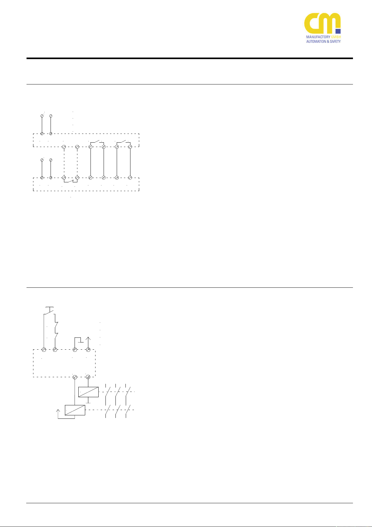
Beispiel: Sichere Kontakterweiterung mit SAFE X4 (mit Querschlussüberwachung)
Über die Freigabestromkreise 13-14
und 23-24 wird das SAFE X4 angesteuert.
Die Rückführkontakte des SAFE X4
(Y1-Y2) werden in den Startkreis des
SAFE 4 eco (alle Varianten) eingeschleift.
Die korrekte Startapplikation entnehmen Sie bitte der vorangegangenen
Beschreibung.
Die Freigabestromkreise des SAFE X4
schalten, sobald die Freigabestromkreise des SAFE 4 eco (alle Varianten)
geschlossen sind.
Bitte beachten Sie die Beschreibung
des SAFE X4, hier finden Sie auch weitere Vorschläge zu Kontakterweiterungen.
Max. erreichbar: Kat. 4, SIL3, PLe
(Beachten Sie hierzu die maximale Anzahl
der Geräte!)
Beispiel: Sichere Kontakterweiterung mit externen Schützen (mit
Querschlussüberwachung)
Über die Freigabestromkreise 13-14
und 23-24 werden die externen
Schütze angesteuert.
Die Rückführkontakte der externen
Schütze werden in den Startkreis des
SAFE eco (alle Varianten) eingeschleift.
In diesem Beispiel ist ein zusätzlicher
Starttaster vorgesehen.
Die externen Schütze schalten, sobald
die Freigabestromkreise des SAFE 4
eco (alle Varianten) geschlossen sind.
Die korrekte Startapplikation entnehmen Sie bitte der vorangegangenen
Beschreibung.
Bitte beachten Sie die Beschreibungen
der externen Schütze / Relais.
Bitte beachten Sie fernerhin, dass ausschließlich Relais und Schütze mit
Zwangsführung zugelassen sind.
Max. erreichbar: Kat. 4, SIL3, PLe
(Beachten Sie hierzu die maximale Anzahl
der Geräte)
Example: Safe contact expansion with SAFE X4 (with cross
circuit monitoring)
The SAFE X4 is triggered by the
safety contacts 13-14 and 23-24.
The loopback contacts of the SAFE
X4 (Y1-Y2) are looped into the start
circuit of the SAFE 4 eco (all variants).
Please see the correct start application above.
The safety circuits of the SAFE X4
close as soon as the safety contacts
of the SAFE 4 eco (all variants) close.
Please refer to the manual of the
SAFE X4.
Max. achievable: cat. 4, SIL3, PLe
(Remark the maximum number of devices!)
Example: Safe contact expansion with external contactors
(with cross circuit monitoring)
The external contactors are triggered
by the safety contacts 13-14 and
23-24.
The loopback contacts of the external
contactors are looped into the start
circuit of the SAFE 4 eco (all variants). In this example an addional
start button is mounted.
Please see the correct start application above.
The safety circuits of the external contactors close as soon as the safety
contacts of the SAFE 4 eco (all variants) close.
Please refer to the manual of the external contactors.
Please continue to refer that only forcibly guided relais and contactors are
valid.
Max. achievable: cat. 4, SIL3, PLe
(Remark the maximum number of devices!)
Page 19

SAFE 4 eco
Gerätevarianten / Devices
Name / Name: Spannung / Voltage: Artikel-Nummer. / Article number:
SAFE 4 eco 24 V AC/DC 45000
SAFE 4 eco 115 V AC 45079
SAFE 4 eco 230 V AC 45080
SAFE 4.1 eco 24 V AC/DC 45069
SAFE 4.1 eco 115 V AC 45325
SAFE 4.1 eco 230 V AC 45326
SAFE 4.2 eco 24 V AC/DC 45317
SAFE 4.2 eco 115 V AC 45318
SAFE 4.2 eco 230 V AC 45319
SAFE 4.3 eco 24 V AC/DC 45320
SAFE 4.3 eco 115 V AC 45321
SAFE 4.3 eco 230 V AC 45322
200803
19
 Loading...