

Page 1
SAFE 4/4.1
CM Manufactory GmbH
Otto-Hahn-Str. 3
D-72406 Bisingen
Tel. +49-(0)7476-9495-0
Fax. +49-(0)7476-9495-195
www.cm-manufactory.com
Zielgruppe/
Target audience
Zeichenerklärung/
Explanation of signs
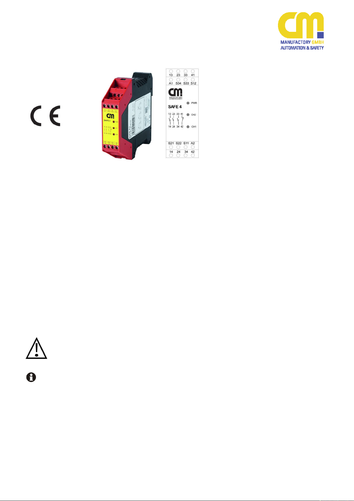
SAFE 4/4.1
Original Bedienungsanleitung
Sicherheitsschaltgerät für Not-HaltKreise und Schutztürüberwachungskontakte
Einleitung
Diese Bedienungsanleitung soll Sie mit
dem Not-Halt Sicherheitsrelais und
Schutztürwächter SAFE 4/4.1 vertraut
machen.
Die Bedienungsanleitung richtet sich an
folgende Personen:
Qualifizierte Fachkräfte, die Sicher-
heitseinrichtungen für Maschinen und
Anlagen planen und entwickeln und
mit den Vorschriften über Arbeitssicherheit und Unfallverhütung vertraut
sind.
Qualifizierte Fachkräfte, die Sicher-
heitseinrichtungen in Maschinen und
Anlagen einbauen und in Betrieb
nehmen.
In dieser Bedienungsanleitung werden
einige Symbole verwendet, um wichtige
Informationen hervorzuheben:
Dieses Symbol steht vor Textstellen, die
unbedingt zu beachten sind. Nichtbeachtung führt zur Verletzung von Personen oder zu Sachschäden.
Dieses Symbol kennzeichnet Textstellen,
die wichtige Informationen enthalten.
Dieses Zeichen kennzeichnet auszuführende Tätigkeiten.
Nach diesem Zeichen wird beschrieben,
wie sich der Zustand nach einer ausgeführten Tätigkeit ändert.
©
Copyright
gen, die dem technischen Fortschritt dienen, vorbehalten.
Alle Rechte vorbehalten. Änderun-
Original operating instruction
Safety controller for e-stop and safety
gate monitoring applications
Introduction
This operating instruction should make
you familiar with the emergency stop and
safety gate monitoring relay SAFE 4/4.1
The operating instruction is addressed to
the following persons:
Qualified professionals who plan and
develop safety equipment for machines and plants and who are familiar with the safety instructions and
safety regulations.
Qualified professionals, who install
safety equipment into machines and
plants and put them into operation.
The operating instruction contains several symbols which are used to highlight
important information:
This symbol is placed in front of text
which has to be absolutely paid attention
to. Nonobservance leads to serious injuries or damage to property.
This symbol is placed in front of text,
which contains important information.
This sign is placed in front of activities.
After this sign follows a description on
how the situation has changed after an
activity is performed.
Copyright
©
serve technical improvements are reserved.
All rights reserved. Changes, which
200803 1
Page 2
SAFE 4/4.1
Bestimmungsgemäße
Verwendung
Application:
Zu Ihrer Sicherheit
For your safety
Sicherheitshinweise
Das Sicherheitsrelais SAFE 4 / 4.1 ist
bestimmt für den Einsatz in:
Einkanalige und zweikanalige Schal-
tungstechnik für Not-Halt oder
Schutztürüberwachungen
SAFE 4 mit Überwachung der Start-
taste
SAFE 4.1 ohne Überwachung der
Starttaste
Personen - und Sachschutz sind nicht
mehr gewährleistet, wenn das Sicherheitsrelais nicht entsprechend seiner
bestimmungsgemäßen Verwendung
eingesetzt wird.
Beachten Sie unbedingt die folgenden
Punkte:
Das Gerät darf nur unter Beachtung
dieser Bedienungsanleitung von
Fachpersonal installiert und in Betrieb genommen werden, das mit den
geltenden Vorschriften über Arbeitssicherheit und Unfallverhütung vertraut ist. Elektrische Arbeiten dürfen
nur von Elektrofachkräften durchgeführt werden.
Beachten Sie die jeweils gültigen
Vorschriften, insbesondere hinsichtlich der Schutzmaßnahmen.
Reparaturen, insbesondere das Öff-
nen des Gehäuses, dürfen nur vom
Hersteller oder einer von ihm beauftragten Person vorgenommen werden. Ansonsten erlischt jegliche Gewährleistung.
Vermeiden Sie mechanische Er-
schütterungen beim Transport oder
im Betrieb; Stöße größer 5g / 33Hz
können zur Beschädigung des Gerätes führen.
Montieren Sie das Gerät in einem
staub- und feuchtigkeitsgeschützten
Gehäuse; Staub und Feuchtigkeit
können zu Funktionsstörungen führen.
Sorgen Sie für eine ausreichende
Schutzbeschaltung bei kapazitiven
und induktiven Lasten an den Ausgangskontakten.
In regelmäßigen Zeitabständen sollte
das Not-Halt Relais ausgelöst werden und auf richtige Funktion geprüft
werden (mindestens jedes halbe Jahr
oder im Wartungszyklus der Anlage).
Safety indications
The safety relay SAFE 4 / 4.1 can be
used for:
Single and two channel capability for
emergency stop or safety gates
SAFE 4 with monitoring of the start
button
SAFE 4.1 for automatic start (without
reset monitoring)
Person and object-protections aren’t
guaranteed, if the safety relay isn’t used
by adequate define application.
Please note the following points:
The unit should only be installed and
operated by persons, who are familiar with both, these instructions and
the current regulations for safety at
work and accident prevention.
Follow local regulations as regards
preventative measures.
Any guarantee is void following
opening of the housing or unauthorized modifications.
Avoid mechanical vibrations greater
than 5 g / 33 Hz when transporting
and in operation.
The unit should be panel mounted in
an enclosure rated at IP 54 or better,
otherwise dampness or just could
lead to function impairment.
Adequate fuse protection must be
provided on all output contacts with
capacitive and inductive loads.
The emergency stop relay should be
test in a defined time period (each
half year or after each check of the
plant).
200803 2
Page 3
SAFE 4/4.1
13-14, 23-24, 33-34
S11-S12, S21-S22
41-42
S33-S34
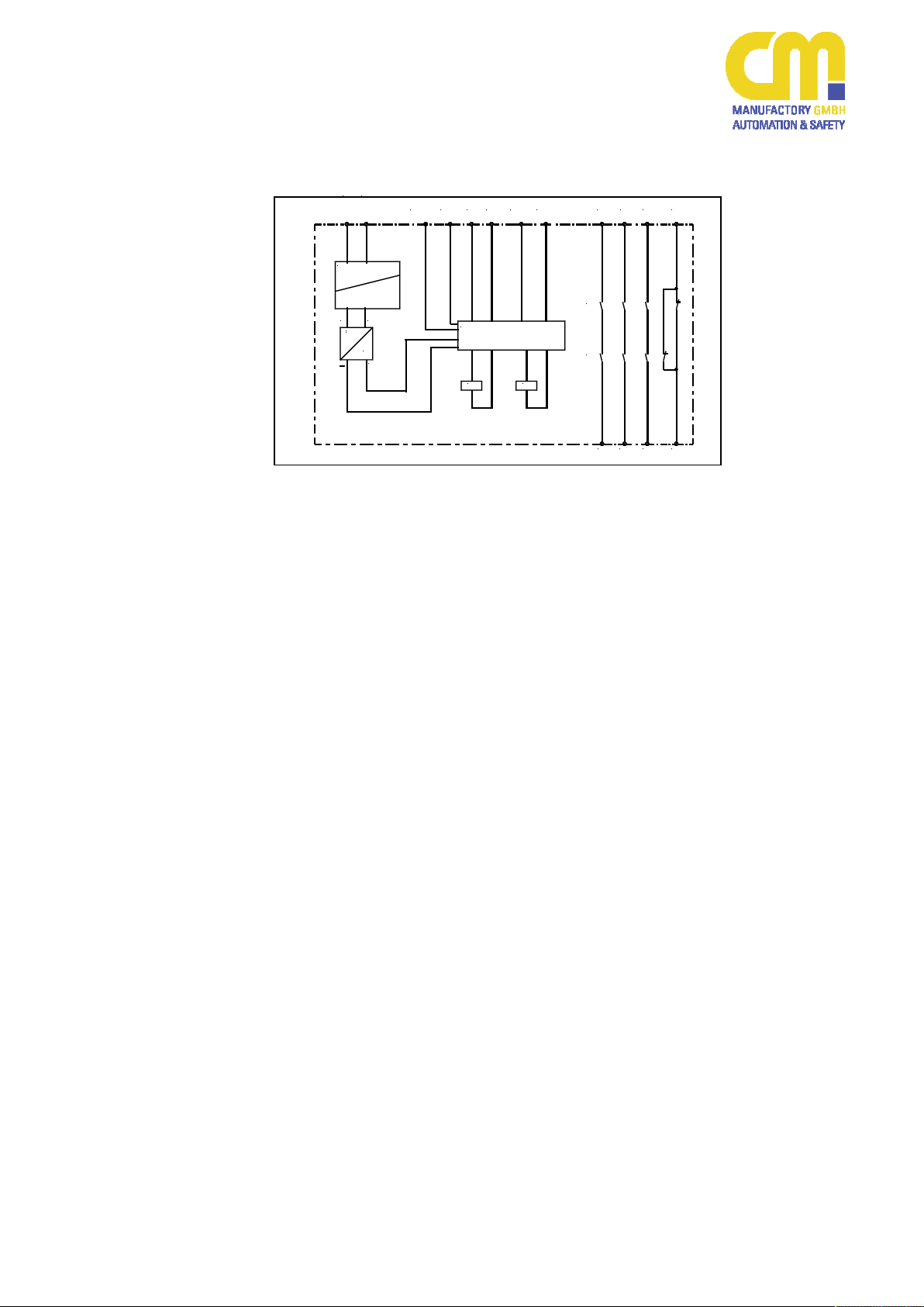
Aufbau und Funktionsweise
Sicherheitsstrompfade (Schließer)
Signalisierungsstrompfad (Öffner)
Start-Taster
Not-Halt Kanal 1 und 2
Für das Betreiben des Gerätes muss
eine Hilfsspannung an die Klemmen A1
und A2 angelegt werden. Die LED
‘Power‘ leuchtet.
Die Anschlussklemmen S11, S12, S21
und S22 werden nach den entsprechenden Anwendungsbeispielen beschaltet.
Zum START des Gerätes muss die
Klemme S33 mit S34 über einen Schließerkontakt überbrückt werden.
Danach sind die Kontakte 13-14, 23-24,
33-34 geschlossen, der Kontakt 41-42
geöffnet. Die LED´s ‘Channel 1‘ und
‘Channel 2‘ leuchten.
In Reihe zu dem START-Taster kann die
Schaltung eines externen Schützes
überwacht werden (siehe Anwendungsbeispiel 3).
A1
(+)A2(-)
elektr. Sicherung
electr. fuse
Transformator
transformer
~ ~
~
~
=
+
S33 S11
S34
Überwachungslogik /
monitoring logic
K1
S12
Assembly and function
(function circuit diagram)
13
S22S21
K1
K2
K2
safety circuits (normally open)
auxiliary circuits (normally close)
start
emergency stop channel 1 and 2
A supply voltage must be applied at terminals A1 and A2. The ‘Power‘ LED illuminates.
Terminals S11, S12, S21 and S22 have
to be wired up as it is shown in the application examples.
To START the unit, terminals S33 and
S34 must be bridged with a normally
open contact. The unit works if you close
this contact.
At this time the contacts 13-14, 23-24
and 33-34 are closed, contact 41-42 is
opened. The LED´s ‘Channel 1‘ and
‘Channel 2‘ illuminate.
In series to the START-button an
external contactor can be controlled
(see application 3).
3323 41
14
3424 42
200803 3
Page 4
SAFE 4/4.1
Mechanische Montage
Mechanical mounting
Elektrischer Anschluss
Electronic connection
Montage und Inbetriebnahme
Für eine sichere Funktion muss das Sicherheitsrelais in ein staub- und feuchtigkeitsgeschütztes Gehäuse eingebaut
werden (IP54).
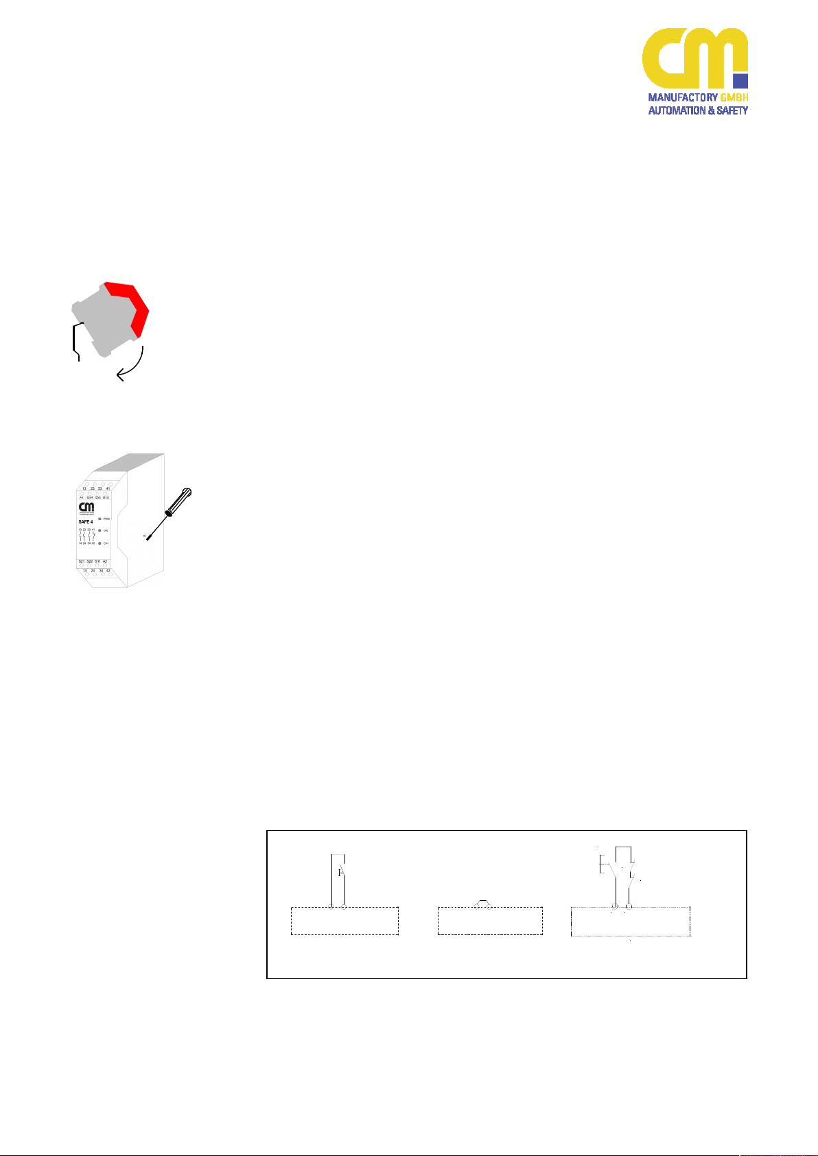
Montieren Sie das Sicherheitsre-
lais auf eine Normschiene.
Das SAFE4/4.1 (230VAC / 115VAC /
48VAC) ist für den nicht angereihten
Betrieb zugelassen. Der Betrieb von
mehreren Geräten oder mit anderen
Fremdwärmequellen im angereihten Zustand ist nicht zugelassen und erfolgt auf
eigene Verantwortung. Bitte beachten
Sie hierzu die gültigen technischen Vorschriften.
Führen Sie die Verdrahtung entsprechend des Verwendungszweckes durch.
Orientieren Sie sich dabei an den Anwendungsbeispielen. Generell ist das
Sicherheitsrelais nach folgenden Angaben zu verdrahten:
1. Aktivierungs- und Rückführungskreis
schließen
Automatische Aktivierung:
Brücken Sie die An-
Schlussklemmen
S33-S34
Bedingte Aktivierung:
Taster an S33-S34 anschließen
(keine Brücke an S33-S34). Externe Schütze werden in Reihe
zum START-Taster an die
Klemmen S33-S34 angeschlossen.
Start
S34
S33
SAFE 4
Start über Start-Taste
with start control
S33
S34
SAFE 4.1
automatisch er Start
without start control
Mounting and opening
The unit should be panel mounted in an
enclosure rated at IP 54 or better, otherwise dampness or dust could lead to
function impairment.
There is a notch on the rear of
the unit for DIN-Rail attachment.
The device SAFE4/4.1 (230VAC /
115VAC / 48VAC) is not approved for the
operation side by side. The operation of
several devices or with external heat
sources side by side is not approved and
effects on your own risk. Please notice
the applicable regulations.
Carry out the wire appropriate the use.
According to the examples of application.
General the safety-relay has to be wired
under following specifications:
1. Close the feedback control loop and
the activation circuit
Automatic activation:
Bridge S33-S34
Conditional activation:
Connect button on S33-S34 (no
bridge on S33-S34). N.C. contacts of external contactors are
wired in series with the STARTbutton at the terminals S33-S34.
.
Start
K2 ext
K1 ext
S33
S34
Start über Start-Taste und Anschluß
Maschinenfreigabekreise / Schützkontrolle
Start with start bottom and detection of external
conductors
200803 4
Page 5

SAFE 4/4.1
2. Eingangskreis schließen
Einkanalig:
Schließen Sie den Kontakt des
Auslöseelementes an die positive Versorgungsspannung und
die Anschlussklemme A1(+) an.
Kategorie 4 nur bei Verwendung
von zwangstrennenden Schaltern
und Verlegung der Kabel in getrennten Mantelleitungen.
Zweikanalig:
Schließen Sie die Kontakte des
Auslöseelementes an S11-S12
und S21-S22 an.
Die Verdrahtung der Versorgungsspannung ist abhängig vom Gerätetyp (siehe Typenschild am Gerät).
3. Versorgungsspannung Uv:
24V AC/DC oder 48V AC, 115V AC,
230V AC
Einkanalig:
Schließen Sie die Versorgungs-
spannung UV (+) / L (Phase) über
den Kontakt des Not-Halt bzw.
Schutztürschalters an die Klemmen A1(+). Schließen Sie den
UV(-) / N (Nullleiter) direkt an die
Klemme A2(-) an.
Bei 48V, 115V und 230VGeräten muss der Erdanschluss
an S21 angeschlossen werden.
Zweikanalig:
Schließen Sie die Versorgungs-
spannung UV an die Klemmen
A1(+) und A2(-) an. Bei 48V,
115V und 230V-Geräten muss
der Erdanschluss an S21 ange-
schlossen werden.
Beachten Sie unbedingt die maximalen
Leitungslängen!
24 VAC/DC24 VAC/DC
A1 (+) A2 (-)
einkanalig / single-channel
Auslöseelement /
trigger
element
2. Close input circuit
Single-channel:
Connect contacts from trigger el-
ement to positive supply voltage
and A1(+).
You have category 4, when using restricted guided switches and lead the
wiring in separate coated cables.
Dual-channel:
connect contacts from trigger el-
ement to S11-S12 and S21-S22.
3. Supply voltage Uv:
Please note the max. lengths of
cables!
S11 S12 S22 S21
zweikanalig / dual-channel
The wire of the supply voltage is dependent on device-model (see type
plate on the device)
24V AC/DC or 48V AC, 115V AC,
230V AC
Single channel:
The Supply voltage UV (+) / L has
to be connected over the contact
from emergency stop / safety
gate monitoring to the terminals
A1(+) and UV (-) / N directly to
terminal A2.
At 48V, 115V and 230V devices
the ground wire has to be connected to S21.
Dual-channel:
The supply voltage UV has to be
connected to the terminals A1(+)
and A2(-). At 48V, 115V and
230V devices the ground wire
has to be connected to S21.
Auslöseelement /
trigger
element
200803 5
Page 6

SAFE 4/4.1
Erdschluß bei
AC - DC-Variante
(mit elektr. Sicherung) /
Earth fault
AC / DC-version
(with electronic fuse
protection)
Fehlfunktion der
Kontakte /
Faulty contact
Functions
LED ‘Power‘ leuchtet
nicht / LED ’Power’
does not illuminate
Wartung und Reparatur
Das Sicherheitsrelais arbeitet wartungsfrei.
Zum Austausch des Gerätes empfehlen
wir die Kabel 1 zu 1 abzuschrauben und
an das Austauschgerät anzuschrauben.
1. Kabel abschrauben und an dem Austauschgerät anschrauben.
2. Defektes Gerät von der Hutschiene
nehmen.
3. Austauschgerät auf Hutschiene montieren.
Fehler/Störungen, Auswirkung
und Maßnahmen
Die Sicherung löst aus. Die Ausgangskontakte öffnen.
Nach Wegfall der Störursache und
Einhalten der Betriebsspannung ist das
Gerät wieder betriebsbereit.
Bei verschweißten Kontakten ist nach
Öffnen des Ausgangskreises keine neue
Aktivierung möglich.
Gerät muss eingeschickt werden.
UV ist nicht angeschlossen.
UV anschließen.
Externer Kurzschluss vorhanden (z.B.
S11 mit Masse).
Die Verdrahtung überprüfen.
Maintenance and repair
The safety-relay functions maintenancefree.
For exchange of the device, we advisable
the terminals 1 to 1 screw of and to
screw on the exchange-device.
1. You must screw of the cable and
screw on the exchange-device.
2. Take away the defective device from
the DIN-Rail.
3. Mount the new device on the DINRail.
Faults, effects and measures
An electronic fuse release the output
contacts to open.
Once the reason of the disturbance is
removed and the rated voltage is observed, the device is ready for operation.
In the case of welded contacts, further
activation is not possible following an
opening of the input circuit.
Please send back the device to
CM Manufactory GmbH.
UV is not connected
connect UV
External short circuit exists (e.g. S11 with
ground).
Check wiring
200803 6
Page 7

SAFE 4/4.1
Nur eine/keine LED
(Kanal 1 oder 2) leuchtet / Only one / no LED
(Channel 1 or 2) illuminate
Der Abschaltimpuls ist zu kurz.
Das Auslöseelement länger betätigen
oder das Netz ab und wieder einschalten
(Reset).
Ein Verdrahtungsfehler liegt vor.
Verdrahtung der Kanäle überprüfen.
The turn-off pulse is too short.
Activate the trigger element longer or
reset the grid.
A Wiring error exists.
Check the wiring of the channels
200803 7
Page 8

or Version 230V AC or Version 115V AC or Version 48V AC.
Spannungsbereich / voltage range
0,90 ...1,1 UV
Frequenz (AC-Variante) / frequency (AC-type)
50 ... 60 Hz
Leistungsaufnahme ca. / power consumption appr.
48/115/230VAC: ca. 3,7 VA, 24V DC: 3 W, 24V AC: 5 VA
Leiteranschluß / conductor connection
2 x 1,5 mm2 Massivdraht (Cu) / massive wire
UL: Use 60/75°C copper wire only!
max. conductor length (input circuit)
4 x 100m ( zweikanalig / dual channel)
Leiterquerschnitt / conductor cross-section
2 x 1,5 mm2 / 4 x 1,5mm²
Kapazität / capacity
150 nF/km
Temperatur / temperature
+ 25°C
Kontaktbestückung / contact-allocation
3 Schließer / 1 Öffner 3 normally safety open / 1 auxiliary closed
Kontaktart / contact type
Relais zwangsgeführt / relay positive guided
AgSnO2 or comparable material
Schaltspannung / switching voltage
240V AC, 24V DC
Schaltstrom / switching current
5 A, Summenstrom/ total current 13,8A
Schaltstrom min. / switching current min.
10mA
DIN EN 60947-5-1
DC 13 24 V / 5 A
Schaltleistung max. / max. switching capacity
1200 VA (ohmsche Last) / 1200 VA (ohms load)
Mechanische Lenbensdauer / mechanical lifetime
107 Schaltspiele / switches
Elektrische Lebensdauer / electrical lifetime
105 Schaltspiele / switches (DC 24V/2A)
clearance
basis isolation: over voltage category 3 / 250 V
Öffner: 4A Neozed gL/gG / NC contact: 4A Neozed gL/gG
entsp. / acc IEC60947-5-1
Öffner / NC-contacts: 6A
*) Short Circuit Protection Device
Eingänge) / restart time (min. switch off time of the inputs)
0,5 s
einkanalig / single channel
< 130 ms
Gehäusematerial / housing material
Polyamid PA 6.6
Abmessungen (BxHxT) in mm / dimensions ( bxhxd )
22,5 x 114,5 x 99
Befestigung / fastening
Schnappbefestigung für Normhutschiene / click-fastening for DIN-Rail
Luftfeuchtigkeit / humidity
Wechselklima /alternating climate 95% 0-50°C
connection terminals
(UL: „Tighten to 0.5-0.6 N.m. Overtorquing may cause enclosure breakage“)
Gewicht mit Klemmen / weight with terminals
max. 165g
Lagerung / storage
In trockenen Räumen / in dry areas
Umgebungstemperatur / operating temperature
-25°C ... +55°C ( UL:…+40°C)
Schutzart Klemmen / terminal type
IP 20
Schutzart Gehäuse / housing type
IP 40
contacts
8g / 2g
Zertifizierungen / certifications
Geprüft nach / tested in accordance with
EN ISO 13849-1
Erreichtes Level/Kategorie / achieved level/category
Performance Level e , Kat.4
154 “hoch/high”
DC
99% “hoch/high”
CCF
erfüllt/achieved
SAFE 4/4.1
Technische Daten / Technical Data
Elektrische Daten / electrical data
Versorgungsspannung Uv / supply voltage Version 24V AC/DC
Leitungsdaten / conductor data
2 x 1,5 mm2 Litze (Cu) mit Hülse / strand with hull
Max. Leitungslängen (Eingangskreis) /
2 x 100m ( einkanalig / single channel)
Kontaktdaten / contact data
Kontaktmaterial / contact material AgSnO2 oder vergleichbares Material /
Max. Schaltvermögen / max. switching capability
Kriech- und Luftstrecken / creeping distance and
Kontaktabsicherung / contact security Schließer: 6,3A flink / NO contact: 6,3A brisk
Kurzschlussfestigkeit / Short Circuit Withstand
Weld Free Protection at I
SCPD*) (Vorsicherung / Fuse links), Gebrauchskategorie / size D01
gL/gG nach / acc IEC IEC60269-1; IEC60269-3-1; VDE036-T301
PSCC
≥1kA
AC 15 230 V / 5 A
-VDE 0160 für Verschmutzungsgrad 2,
Überspannungskategorie 3 / 250 V
VDE 0160 at pollution grade 2,
over voltage category 3 / 250 V
-Basisisolierung: Überspannungskategorie 3 / 250 V
Schließer / NO-contacts: 6A
Wiederbereitschaftszeit (minimale Abschaltzeit der
Rückfallverzögerung /delay on deenergisation
zweikanalig / dual channel
Mechanische Daten / mechanical data
Anzugsmoment für Anschlussklemmen / Torque setting for
24V DC: < 30 ms, AC: < 50ms
min. 0,5 Nm / max. 0,6 Nm
Umgebungsdaten / environmental data
Stoßfestigkeit Schließer/Öffner / shock resistance NO/NC
MTTFD [Jahre] / MTTFD [years]
PFHD [1/h] 1,61*10-8
200803 8
Page 9

SAFE 4/4.1
Ub
Not-
START
Halt/
ESTOP
S34S33 S22
A2(-)A1(+)
bis Kategorie 4*; SIL3; PLd
erreichbar
up to category 4*; SIL3; PLd
reachable
24V AC/DC
START
A2(-)A1(+)
S34S33
bis Kategorie 4; SIL3; PLe
erreichbar
up to category 4; SIL3; PLe
reachable
24V AC/DC
t.
x
e
2
START
K
t.
x
e
1
K
A1(+)
A2(-)
S33 S34
S21 S22
bis Kategorie 4; SIL3; PLe
erreichbar
up to category 4; SIL3; PLe
reachable
bis Kategorie 4*; SIL3; PLd
erreichbar
up to category 4*; SIL3; PLd
reachable
START
24V AC/DC
S1
A2(-)S34S33 A1(+)
S21
NOTAUS/
ESTOP
NOTAUS/
ESTOP
S22S21 S12S11
S12S11 23
13
S22S21 S12S11 23
13
U
ext.
S
ext.
S11
S12
13
1414
K1
ext.
23
24
K2
ext.
231341
Anwendungsbeispiele
Beispiel 1: Einkanalige
Not-Halt-Schaltung (ohne Querschlusssicherheit).
Mit dem Starttaster wird das Gerät akti-
4133
viert. Über den Not-Halt-Schalter fallen
die Kontakte in ihre Grundstellung zurück.
Beispiel 2: Zweikanalige Not-HaltSchaltung (mit Querschlusssicherheit).
Bei der zweikanaligen Not-HaltSchaltung mit Querschlusssicherheit wird
der Klemmenanschluss S11, S12, S21
und S22 verwendet. Mit dem START-
4133
Taster wird das Gerät aktiviert. Die Kontakte 13-14, 23-24 und 33-34 schließen.
Über den Not-Halt-Schalter fallen die
Kontakte in ihre Grundstellung zurück.
Beispiel 3: Zweikanalige Not-HaltSchaltung mit externer Kontakterweiterung (2Schütze), Kontaktüberwachung und Querschlusssicherheit.
In diesem Beispiel werden zwei externe
Schütze mit Kontaktzwangsführung verwendet. Je ein Öffnerkontakt dieser beiden Schütze muss in Reihe zum START-
33 41
Taster an die Klemmen S33 und S34
angeschlossen werden. Über einen
Schalter S ext. können die externen
Schütze zu einem beliebigen Zeitpunkt
dazugeschaltet bzw. abgeschaltet werden, wenn das SAFE 4... aktiviert ist. Die
Anschlussleitungen für die Schütze sollten zur Vermeidung von Querschlüssen
getrennt verdrahtet werden.
Beispiel 4: Einkanalige Schutztürüberwachung(ohne Querschlusssicherheit).
Wird der Schutztürtaster S1 geschlossen,
bleiben die Ausgangskontakte unverändert. Erst mit Freigabe wird das Gerät
aktiviert. Die Kontakte13-14,23-24
33
schließen. Beim Öffnen des Schutztürtasters fallen die Kontakte in ihre Grundstellung zurück.
Achtung: Die Abfallverzögerung kann
sich bei 48/115/230V AC – Geräten bis
zu 130 ms verlängern.
Examples for applications
Example 1: Single-channel emergency
stop (without opposite between channels).
Pressing the START-button, the unit will
be activated. Contacts 13-14 and close.
Pressing the emergency stop will reset
the contacts.
Example 2: Dual-channel emergency
stop (with opposite between channels)
For this application the terminal wiring
S11, S12, S21 and S22 must be used.
With the START-button the device will be
activated. The contacts 13-14, 23-24 and
33-34 are closed. Pressing the emergency stop initiates a stop and outputs open
immediately.
Example 3: Dual-channel emergency
stop with external contact extension
(2 contactors), contact monitoring and
opposite polarity between channels.
This application uses two external contactors with positive guidance. One normally closed contact of each external
contactor must be connected in series to
the START-button to the terminals S33
and S34. Through the switch S ext. the
external contactors can be operated or
turned off at any time if the SAFE 4... is
activated.
Example 4: Single-channel safety gate
monitoring.
If the button S1 of the safety gate is
closed the output contacts do not
change. Pressing the START-button
activates the SAFE4. The contacts 1314, 23-24 close.
After the opening of the protection door
switch the contacts return to their normal
position.
Attention: The fall-back-time can increase
up to 130 ms at 48/115/230V AC
devices.
200803 9
Page 10

SAFE 4/4.1
Freigabe/
release
bis Kategorie 4; SIL3; PLe
erreichbar
up to category 4; SIL3; PLe
reachable
24V AC/DC
S2 S1
A2(-)
A1(+)
S34S33
S22S21 S12S11 23
13
bis Kategorie 4; SIL3; PLe
erreichbar
up to category 4; SIL3; PLe
reachable
24V AC/DC
A2(-)S34S33 A1(+) S22S21 S12S11
S2 S1
2313
Beispiel 5: Zweikanalige Schutztürüberwachung (mit Querschlussssicherheit).
Werden die Schutztürschalter S1 und S2
geschlossen, bleiben die Ausgangskontakte unverändert. Erst mit Freigabe wird
41
33
das Gerät aktiviert. Die Kontakte1314,23-24 schließen. Beim Öffnen des
Schutztürtasters fallen die Kontakte unverzögert in ihre Grundstellung zurück.
Beispiel 6: Zweikanalige Schutztürüberwachung mit automatischer Aktivierung und Querschlusssicherheit.
Nur bei SAFE 4.1
In diesem Beispiel erfolgt die Aktivierung
des Gerätes automatisch, da S33 und
S34 überbrückt sind. Wird der Schutztür-
41
33
schalter geschlossen, schließen die Kontakte 13-14, 23-24 und 33-34. Beim Öffnen des Schutztürtasters fallen die Kontakte unverzögert in ihre Grundstellung
zurück. Dieses Anwendungsbeispiel ist
nur mit der Gerätevariante SAFE 4.1
ohne Überwachung der START-Taste
möglich.
Der automatische Start erfolgt schon
beim Anlegen der Versorgungsspannung.
Verdrahtungshinweis für die Ausgangsklemmen 13-14, 23-24,
33-34 und 41-42:
Es sollte die Spannung (L-Leiter bzw.
24V DC), und nicht NULL, über die Ausgänge geschaltet werden um Erd- / Masse- schlüsse erkennbar zu machen.
Zur Schonung der Kontakte empfehlen
wir ein RC-Glied parallel zum Verbraucher zu schalten.
* Kategorie 4 nur bei Verwendung von
zwangstrennenden Schaltern und Verlegung der Kabel in getrennten Mantellei-
Example 5: Dual-channel protection
door monitoring with opposite polarity
between channels.
If the safety gate switches are closed, the
output contacts remain unchanged. After
the release of the unit, the contacts 13-14
and 23-24 close. After opening the protection door switches the contacts return
to their normal position without delay.
Example 6: Dual-channel protection
door monitoring with automatic activation and with opposite polarity between channels.
Only SAFE 4.1
For this application the unit SAFE 4.1 /
SAFE 2.2 has to be used. The activation
works automatically, since the terminals
S33/S34 are bridged. If the protection
door switches close, the contacts 13-14,
23-24 close. After the opening of the
protection door switches the contacts
return to their normal position without
delay.
The automatic start already takes place
when the device is connected to the supply voltage.
Wiring hints for the output terminals
13-14, 23-24, 33-34 and 41-42:
The Voltages (for example L+ or 24 V
DC), and not GND, should be routed via
the terminals. This will help to recognise
shorts to GND or Earth.
Using R-C combination in parallel to
inductive loads can reduce wear out
of contacts.
* You have category 4, when using restricted guided switches and lead the
wiring in separate coated cables.
tungen.
200803 10
Page 11

SAFE 4/4.1
Gerätevarianten / Devices
Name / Name: Spannung / Voltage:
SAFE 4 24 V AC / DC
SAFE 4 48 V AC
SAFE 4 115 V AC
SAFE 4 230 V AC
SAFE 4.1 24 V AC / DC
SAFE 4.1 48 V AC
SAFE 4.1 115 V AC
SAFE 4.1 230 V AC
200803 11
 Loading...