


S
PE0601-xxxx
CML Microcircuits
COMMUNICATION SEMICONDUCTOR
UM0601/2 April 2011 Provisional Issue
Evaluation Kit
User Manual
Features
• CMX7x6x FirmASIC® product range evaluation • Command and control by PC via the
PE0002 interface card or user’s µC
• Serial Flash Option for Function ImageTM with in-
circuit programming
• On-board supply regulators operate from a single
5 volt supply
• Instrumentation interface to differential I and Q
signals (requires additional –5 volt supply)
development application or emulator
• 19.2MHz oscillator, user crystal or
external clock input to CMX7x6x
• On-board access to all CMX7x6x
signals, commands and data
• Interfaces to RF daughterboard with
all necessary signals
1
Brief Description
The PE0601-xxxx Platform Evaluation Kit is designed to assist in the evaluation and application
development of the CMX7x6x range of FirmASIC
comprising a CMX7x6x target IC and appropriate supporting components and circuitry.
The board also incorporates all of the necessary power-supply regulation facilities for operation from a
single 5 volt supply, or a dual +/-5 volt supply if the instrumentation interface is required.
The board is fitted with a C-BUS connector allowing the PE0601 to be operated by connection to either of
the two C-BUS ports on a CML PE0002 Interface Card, and used with the associated PC GUI software, or
by direct connection between the CMX7x6x C-BUS and the user's µC development application or
emulation system.
© 2011 CML Microsystems Plc
®
products. The kit is in the form of a populated PCB

Evaluation Kit for CMX7x6x PE0601-xxxx
The CMX7x6x Function ImageTM (FI) can be loaded, on power-up, directly into the on-board target IC
using the PE0002 interface or the user's system. Alternatively, it can be automatically loaded from the onboard serial memory, on power-up. In this case, the on-board serial memory has to be pre-loaded with the
FI by using the 'Program Serial Memory' tab on the PE0002 GUI software, or by the user’s system
utilising the appropriate ‘thick stub’ programme. All of this software is available from the CML website.
Function images suitable for the CMX7x6x range of products can be downloaded from the CML Technical
Portal.
© 2011 CML Microsystems Plc 2 UM0601/2

Evaluation Kit for CMX7x6x PE0601-xxxx
CONTENTS
Section
1
Page
Brief Description........................................................................................................1
1.1 History.............................................................................................................4
2 Preliminary Information ............................................................................................6
2.1 Laboratory Equipment ....................................................................................6
2.2 Handling Precautions .....................................................................................6
2.2.1 Static Protection .......................................................................................6
2.2.2 Contents - Unpacking...............................................................................6
2.3 Approvals........................................................................................................6
3 Quick Start .................................................................................................................7
3.1 With PE0002...................................................................................................7
3.1.1 Setting-Up.................................................................................................7
3.1.2 Operation..................................................................................................7
3.2 Without PE0002..............................................................................................8
4 Signal Lists.................................................................................................................9
5 Circuit Schematics and Board Layouts ................................................................20
6 Detailed Description................................................................................................22
6.1 Hardware Description...................................................................................22
6.1.1 Power Supplies.......................................................................................22
6.1.2 Clock Options .........................................................................................22
6.1.3 Control Interface .....................................................................................23
6.1.4 Serial Memory.........................................................................................23
6.1.5 Baseband Interfacing..............................................................................23
6.1.6 RF Transceiver Interface........................................................................24
6.1.7 Instrumentation Interface........................................................................24
6.1.8 Digital Interfacing....................................................................................24
6.2 Adjustments and Controls ............................................................................25
6.3 Function ImageTM.........................................................................................26
6.3.1 Load Function ImageTM via C-BUS ........................................................26
6.3.2 Load Function ImageTM from Serial Memory Device..............................27
6.3.3 Program Serial Memory..........................................................................28
6.4 Troubleshooting............................................................................................30
7 Performance Specification .....................................................................................31
7.1 Electrical Performance .................................................................................31
7.1.1 Absolute Maximum Ratings....................................................................31
7.1.2 Operating Limits .....................................................................................31
7.1.3 Operating Characteristics.......................................................................32
7.1.4 Operating Characteristics - Timing Diagrams ........................................33
© 2011 CML Microsystems Plc 3 UM0601/2
Evaluation Kit for CMX7x6x PE0601-xxxx
Table Page
Table 1 – Signal List.......................................................................................................... 15
Table 2 – Test Points ........................................................................................................ 16
Table 3 – Jumpers ............................................................................................................18
Table 4 – LEDs .................................................................................................................19
Table 5 – Clock Select Jumper Positions .........................................................................22
Table 6 – TCXO Component Changes............................................................................. 23
Figure
Page
Figure 1 – Block Diagram
................................................................................................... 5
Figure 2 – PE0601 used with PE0002................................................................................ 7
Figure 3 – PCB Layout: Top ............................................................................................. 20
Figure 4 – PCB Layout: Bottom ........................................................................................ 21
Figure 5 – Function Image™ Load Tab – via C-BUS ....................................................... 26
Figure 6 – Function Image™ Load Tab – from Serial Memory ........................................27
Figure 7 – Program Serial Memory Tab ........................................................................... 28
Figure 8 – Thick Stub Loaded Message Box.................................................................... 29
Figure 9 – Program Serial Memory Complete Message Box ........................................... 29
It is always recommended that you check for the latest product datasheet version from the
Datasheets page of the CML website: [www.cmlmicro.com].
1.1 History
Version Changes Date
2 Differences in the differential signal mapping between PE0601 and various
RF EvKits noted.
Differences in CMX7x6x pin labelling between PE0601 and the various FI
datasheets noted.
1 Original document. 8th June 2010
21st Apr 2011
© 2011 CML Microsystems Plc 4 UM0601/2

Evaluation Kit for CMX7x6x PE0601-xxxx
U
S
B
C
-
&
t
o
o
B
o
tr
n
C
o
l, J
0
1
SSP/GPIO, J7
J16
+V
-V
+V, J23
Supplies
Serial
Memory
+3V3D
Core
+3v3
Speaker
+3V3A
+4V0
-4V0
CMX7x6x
Instrumentation
Interface
Clocks
(19.2MHz
default)
Auxiliary
ADC & DAC,
J13
C-BUS
Master,
J11
RF
Interface,
J22
Audio
Outputs,
J3/4
Audio
Inputs,
J1/2
I/Q_INI/Q_OUT
Figure 1 – Block Diagram
© 2011 CML Microsystems Plc 5 UM0601/2

Evaluation Kit for CMX7x6x PE0601-xxxx
2 Preliminary Information
The PE0601-xxxx is designed to support the CMX7x6x range of FirmASIC
respective Function Image
TM
.
The PE0601-xxxx is supplied with a customer specified target device fitted where xxxx in the
product code is the numerical part of the target device product code.
For example:
To evaluate a CMX7163 Function Image
TM
(FI), order a PE0601-7163.
In this document the PE0601-xxxx will be referred to generically as PE0601.
Note that the Function Image
differently, as a result. The pin numbers will remain unchanged. The datasheet and user manual
appropriate to the product code and Function Image
TM
will redefine many pin functions and so the pins may be labelled
TM
should be used as the definitive reference
of functionality, rather than this PE0601 document, which only uses generic pin names.
®
devices using their
2.1 Laboratory Equipment
The following laboratory equipment is needed to use this evaluation kit:
A 5 volt dc regulated power supply or +/- 5 volt if the instrumentation interface is required.
If the PE0601 is being used with the PE0002 Interface Card, the following items will also be
required:
1. An IBM compatible PC with the following requirements:
• One of the following Windows operating systems installed: 2000sp4 or XPsp2
• USB port
• Minimum screen resolution 800 x 600. Recommended resolution 1024 x 768.
2. A USB type A male to mini B male cable.
3. Software application ES000230.exe, or later version, installed on the PC.
2.2 Handling Precautions
Like most evaluation kits, this product is designed for use in office and laboratory environments.
The following practices will help ensure its proper operation.
2.2.1 Static Protection
This product uses low power CMOS circuits that can be damaged by electrostatic discharge.
Partially damaged circuits can function erroneously, leading to misleading results. Observe ESD
precautions at all times when handling this product.
2.2.2 Contents - Unpacking
Please ensure that you have received all of the items on the separate information sheet (EK0601)
and notify CML within 7 working days if the delivery is incomplete.
2.3 Approvals
This product is not approved to any EMC or other regulatory standard. Users are advised
to observe local statutory requirements, which may apply to this product.
© 2011 CML Microsystems Plc 6 UM0601/2
Evaluation Kit for CMX7x6x PE0601-xxxx
3 Quick Start
This section is divided into two sub-sections. The first is for those users who are using the
PE0601 with a PE0002 controller card and its Windows PC GUI software. The second is for users
who are using the PE0601 by itself, without a PE0002.
3.1 With PE0002
Note that the C-BUS connector, J10, and the power connector J23 are both right angle headers
and are designed to plug directly into sockets J5 (C-BUS 1 port) and J9 respectively, or sockets
J3 (C-BUS 2 port) and J7 respectively, of a PE0002.
3.1.1 Setting-Up
• Refer to the PE0002 user manual and follow the instructions given in the quick start section.
• Ensure the jumpers JP1 and JP2 are open circuit. The BootEn1 and BootEn2 signals are
driven from the PE0002.
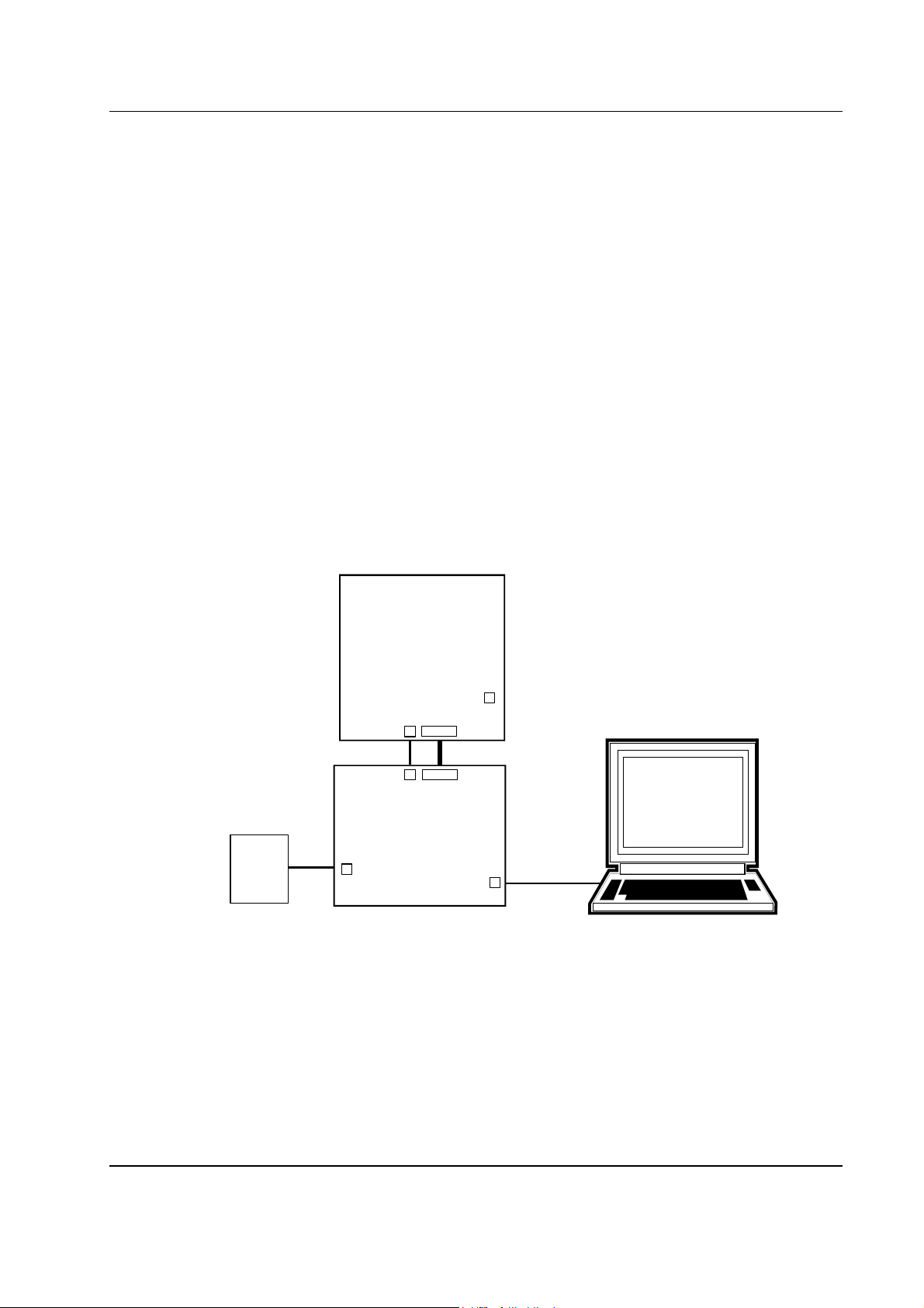
The basic arrangement, when used with the PE0002, is shown below:
3.1.2 Operation
The Function Image
type header file and must be obtained from the CML Technical Portal. There are two methods
available for loading the FI:
Power
Supply
PE0601-xxxx
JP1/2
J23
J9 or J7
+V
PE0002
J8
J10
Direct Connections
J3 or J5
C-BUS
USB Cable
J2
PC
Figure 2 – PE0601 used with PE0002
TM
(FI) must now be loaded into the CMX7x6x device. A FI is provided as a ‘C’
1. Directly from a file on the PE0002 host PC to the CMX7x6x
© 2011 CML Microsystems Plc 7 UM0601/2

Evaluation Kit for CMX7x6x PE0601-xxxx
2. From the on-board PE0601 serial memory. To use this method the serial memory must first
be programmed with the FI by using the 'Program Serial Memory' tab on the PE0002 GUI
software.
The PE0601 should now be ready for evaluation of the CMX7x6x with the chosen FI.
Please note that to access the CML Technical Portal you need to be authorised by a member of
the CML sales staff. Please contact your local distributor, representative or area sales manager.
3.2 Without PE0002
As an alternative to using the PE0002 controller kit, users may control the CMX7x6x target device
with a user-supplied host controller card. C-BUS connections are made via connector J10.
The power-up, or boot state of the CMX7x6x BOOTEN1 and BOOTEN2 pins may be set using
jumpers JP1 and JP2. Consult the relevant CMX7x6x documentation for valid modes. A jumper
in-circuit corresponds to a ‘0’ state on the boot pins. Alternatively the state of these pins may be
set via the connector, J10, pins 13 and 14. If jumpers JP1 and JP2 are left open circuit and the
BOOTEN pins are not driven from connector J10, then by default, they are pulled high by the
CMX7x6x device.
A FI for the CMX7x6x device must be either included in the customer’s host system and loaded
into the CMX7x6x device on power-up or programmed into the on-board serial memory following
the guidelines in the application note: ‘Writing a Function Image
from the Application Notes area of the CML website.
TM
to Serial Memory’; available
© 2011 CML Microsystems Plc 8 UM0601/2

Evaluation Kit for CMX7x6x PE0601-xxxx
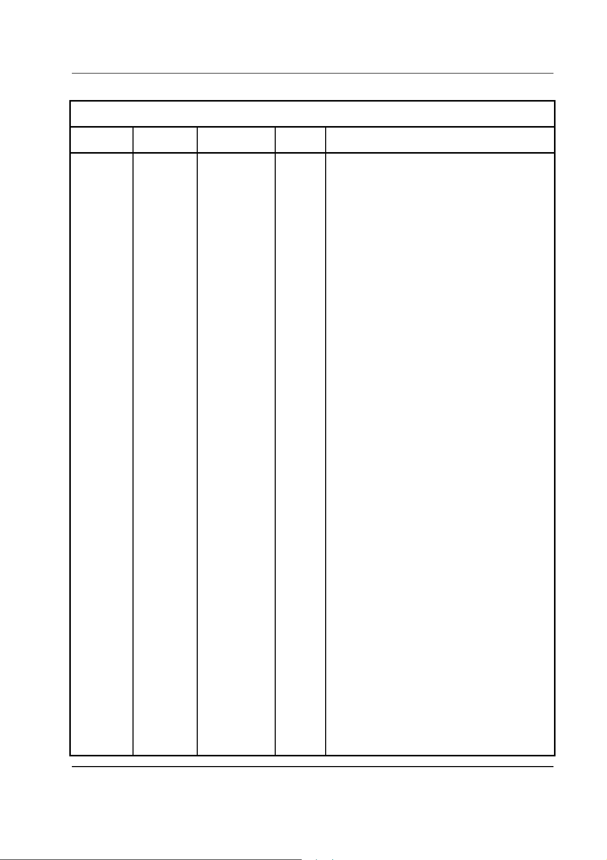
4 Signal Lists
CONNECTOR PINOUT
Connector
Ref.
Connector
Pin No.
Signal
Name
Signal
Type
J1 TIP IP1 I/P Audio 1 input.
RING N/C -
SLEEVE GNDA PWR Analogue ground.
J2 TIP IP2 I/P Audio 2 input.
RING N/C -
SLEEVE GNDA PWR Analogue ground.
J3 TIP SPKR1_P O/P Speaker 1 (8ohm) +ve.
RING N/C -
SLEEVE SPKR1_N O/P Speaker 1 (8ohm) -ve.
J4 TIP SPKR2 O/P Speaker 2 (32ohm).
RING N/C -
SLEEVE GNDA PWR Analogue ground.
Description
J5 1 CLK EXT I/P External input option for CMX7x6x clock (not
fitted).
J7 1 GPIO0/SSIN/F
BI CMX7x6x signal, FI dependent.
SI
2
3 GPIO2/SSOU
GPIO1/CLKI BI CMX7x6x signal, FI dependent.
BI CMX7x6x signal, FI dependent.
T2
4 GPIO3/TXD BI CMX7x6x signal, FI dependent.
5 GPIO4/RXD BI CMX7x6x signal, FI dependent.
6 GPIO5/IRQN BI CMX7x6x signal, FI dependent.
7 GPIO6/CSN BI CMX7x6x signal, FI dependent.
8 GPIO7/CMD_
BI CMX7x6x signal, FI dependent.
DATA
9 GPIO8/REP_
BI CMX7x6x signal, FI dependent.
DATA
10 GPIO9/SCLK BI CMX7x6x signal, FI dependent.
© 2011 CML Microsystems Plc 9 UM0601/2

Evaluation Kit for CMX7x6x PE0601-xxxx
CONNECTOR PINOUT
Connector
Ref.
Connector
Pin No.
J7 11 GPIO10/SYS
Signal
Name
Signal
Type
Description
BI CMX7x6x signal, FI dependent.
CLK2
12 GPIO11/SYS
BI CMX7x6x signal, FI dependent.
CLK1
13 GPIO12/MOSI
BI CMX7x6x signal, FI dependent.
/SDO
14 GPIO13/SSO
BI CMX7x6x signal, FI dependent.
UT1/FSO
15 GPIO14/MISO
BI CMX7x6x signal, FI dependent.
/SDI
16 GPIO15/SSO
BI CMX7x6x signal, FI dependent.
UT0
17 CLK/CLKO BI CMX7x6x SSP clock signal, FI dependent.
18 N/C -
19, 20 GNDD PWR Digital ground.
J8 1 N/C -
2 SPKR_2_OP O/P Speaker 2 (32ohm) output.
3 GNDA PWR Analogue ground.
4 GNDA PWR Analogue ground.
5 SPKR_1_OP_
O/P Speaker 1 (8ohm) -ve.
N
6 SPKR_1_OP_
O/P Speaker 1 (8ohm) +ve.
P
7 SPKR_3V3 PWR Dedicated 3.3 volt power rail for speaker 1
output.
8 SPKR_1_VDD PWR DC supply for speaker 1.
9 IP2 I/P Audio input.
10 IP1 I/P Audio input.
J10 1 RESETN I/P CMX7x6x Reset control.
2 CSN I/P
Chip Select. Connects to host μC.
3 RFCSN I/P RF Serial Chip Select.
4 CDATA I/P
Serial data input. Connects to host μC.
5 RF_MOSI I/P RF serial data.
© 2011 CML Microsystems Plc 10 UM0601/2
Evaluation Kit for CMX7x6x PE0601-xxxx
CONNECTOR PINOUT
Connector
Ref.
Connector
Pin No.
Signal
Name
J10 6 SCLK I/P
Signal
Type
Description
Serial clock input. Connects to host μC.
7 RF_SCLK I/P RF Serial Clock.
8 RDATA O/P
10 IRQN O/P
Serial data output. Connects to host μC.
Interrupt request. Connects to host μC.
11, 12 GNDD PWR Digital ground.
13 BOOTEN1 I/P CMX7x6x hardware boot control.
14 BOOTEN2 I/P CMX7x6x hardware boot control.
9, 15 to 20 N/C -
J11 1 SSOUT2 BI C-BUS master, spare chip select, FI dependent.
2
SSOUT1 BI C-BUS master, chip select, FI dependent.
3 GPIO6 BI CMX7x6x signal, FI dependent.
4 SDO BI C-BUS master, command data, FI dependent.
5 GPIO7 BI CMX7x6x signal, FI dependent.
6 CLK BI C-BUS master, serial clock, FI dependent.
7 GPIO8 BI CMX7x6x signal, FI dependent.
8 SDI BI C-BUS master, reply data, FI dependent.
9 GPIO9 BI CMX7x6x signal, FI dependent.
10 GPIO11 BI CMX7x6x signal, FI dependent.
11, 12 GNDD PWR Digital ground.
13 GPIO3 BI CMX7x6x signal, FI dependent.
14 GPIO4 BI CMX7x6x signal, FI dependent.
15
17
16, 18, 19,
GPIO10
SSOUT0
BI
BI
CMX7x6x signal, FI dependent.
C-BUS master, spare chip select, FI dependent.
N/C -
20
J13 1 AUXADC3 I/P Auxiliary ADC input.
2 AUXDAC0 O/P Auxiliary DAC output.
3 AUXADC2 I/P Auxiliary ADC input.
4 AUXDAC1 O/P Auxiliary DAC output.
5 AUXADC1 I/P Auxiliary ADC input.
6 AUXDAC2 O/P Auxiliary DAC output.
© 2011 CML Microsystems Plc 11 UM0601/2

Evaluation Kit for CMX7x6x PE0601-xxxx
CONNECTOR PINOUT
Connector
Ref.
J13 7 AUXADC0 I/P Auxiliary ADC input.
8 AUXDAC3 O/P Auxiliary DAC output.
9, 10 GNDA PWR Analogue ground.
J16 3 +V PWR External supply voltage, nominally +5 volt.
2 0V PWR External supply ground.
1 -V PWR Optional external negative supply voltage,
J17 1 I_IN I/P I channel instrument input, single ended.
J18 1 Q_IN I/P Q channel instrument input, single ended.
J19 1 I_OUTP_I I/P I channel output positive, instrumentation input.
Connector
Pin No.
2 I_OUTP O/P I channel output positive.
3 I_OUTN_I I/P I channel output negative, instrumentation input.
4 I_OUTN O/P I channel output negative.
Signal
Name
Signal
Type
Description
nominally -5 volt.
5, 6 GNDA PWR Analogue ground.
7 Q_OUTP_I I/P Q channel output positive, instrumentation input.
J20 1 I_OUT O/P I channel instrumentation output, single ended.
J21 1 Q_OUT O/P Q channel instrumentation output, single ended.
J22
8 Q_OUTP O/P Q channel output positive.
9 Q_OUTN_I I/P Q channel output negative, instrumentation input.
10 Q_OUTN O/P Q channel output negative.
1 RF_MOSI
O/P
RF Serial Data.
2 RF_SCLK I/P RF Serial Clock.
3
GPIO12/MOSI
BI CMX7x6x signal, FI dependent.
/SDO
4
GPIO14/MISO
BI CMX7x6x signal, FI dependent.
/SDI
© 2011 CML Microsystems Plc 12 UM0601/2

Evaluation Kit for CMX7x6x PE0601-xxxx
CONNECTOR PINOUT
Connector
Ref.
J22
Connector
Pin No.
5 GNDD PWR Digital ground.
6
7
8 GNDD PWR Digital ground.
9
10 GNDD PWR Digital ground.
11 NC -
12, 13 +V_RF PWR External supply voltage, nominally +5 volt.
14 GNDA PWR Analogue ground.
15 CLKEXT I/P External input option for CMX7x6x clock.
16 AUXDAC0 O/P Auxiliary DAC output.
17 AUXDAC2 O/P Auxiliary DAC output.
18 GNDA PWR Analogue ground.
19 AUXADC3 I/P Auxiliary ADC input.
20 AUXADC1 I/P Auxiliary ADC input.
21 GNDA PWR Analogue ground.
22 IP1 I/P Audio input.
23 IP2 I/P Audio input.
24 SPKR_2_OP O/P Speaker 2 (32ohm).
25 I_OUTP O/P I channel output positive.
26 I_OUTN O/P I channel output negative.
27, 28 NC -
29 Q_OUTP O/P Q channel output positive.
30 Q_OUTN O/P Q channel output negative.
31 GNDA PWR Analogue ground.
32 I_INP I/P I channel input positive.
33 I_INN I/P I channel input negative.
34, 35, 36,
37
38 Q_INP I/P Q channel input positive.
39 Q_INN I/P Q channel input negative.
Signal
Name
GPIO13/SSO
Signal
Type
BI CMX7x6x signal, FI dependent.
UT1/FSO
GPIO2/SSOU
BI CMX7x6x signal, FI dependent.
T2
GPIO11/SYS
BI CMX7x6x signal, FI dependent.
CLK1
GNDA PWR Analogue ground.
Description
© 2011 CML Microsystems Plc 13 UM0601/2

Evaluation Kit for CMX7x6x PE0601-xxxx
CONNECTOR PINOUT
Connector
Ref.
J22
Connector
Pin No.
Signal
Name
Signal
Type
Description
40 GNDA PWR Analogue ground.
41 AUXADC0
42 AUXADC2
I/P
I/P
Auxiliary ADC input.
Auxiliary ADC input.
43 GNDA PWR Analogue ground.
44 AUXDAC3
O/P
Auxiliary DAC output.
45 AUXDAC1 O/P Auxiliary DAC output.
46, 47, 48 GNDA PWR Analogue ground.
49 +V PWR External supply voltage, nominally +5 volt.
50 NC -
51 GNDD PWR Digital ground.
52
GPIO10/SYS
BI CMX7x6x signal, FI dependent.
CLK2
53 GNDD PWR Digital ground.
54 GPIO4/RXD BI CMX7x6x signal, FI dependent.
55
GPIO0/SSIN/F
BI CMX7x6x signal, FI dependent.
SI
56 GNDD PWR Digital ground.
57
GPIO5/IRQN BI CMX7x6x signal, FI dependent.
58 CLK/CLKO BI CMX7x6x SSP clock signal, FI dependent.
59 RFCSN O/P RF Serial Chip Select.
60 GPIO1/CLKI BI CMX7x6x signal, FI dependent.
J23 1, 2 GNDD PWR Digital ground.
3 to 6 +V PWR External supply voltage – daisy-chained from
PE0002.
J24 1 I_INP_I O/P I channel input positive, instrumentation output.
2 I_INP I/P I channel input positive.
3 I_INN_I O/P I channel input negative, instrumentation output.
4 I_INN I/P I channel input negative.
5, 6 GNDA PWR Analogue ground.
7 Q_INP_I O/P Q channel input positive, instrumentation
output.
© 2011 CML Microsystems Plc 14 UM0601/2
8 Q_INP I/P Q channel input positive.

Evaluation Kit for CMX7x6x PE0601-xxxx
CONNECTOR PINOUT
Connector
Ref.
J24
Connector
Pin No.
Signal
Name
9 Q_INN_I O/P Q channel input negative, instrumentation
Signal
Type
output.
10 Q_INN I/P Q channel negative positive.
Table 1 – Signal List
Notes: BI = Bidirectional
HiZ = High impedance
I/P = Input
N/C = Not connected
O/P = Output
PWR = Power supply connection
Description
© 2011 CML Microsystems Plc 15 UM0601/2

Evaluation Kit for CMX7x6x PE0601-xxxx
Description
Test Point
Ref.
TEST POINTS
Default
Measurement
TP1 - Loop – IP1 - Audio 1 inverting input.
TP2 - Loop – IP2 - Audio 2 inverting input.
TP3 3.3V Pad – CMX7x6x V
TP4 CMX7x6x
Loop – CMX7x6x GPIO11/SYSCLK1 - FI dependent.
BIAS
.
dependent
TP5 CMX7x6x
Loop – CMX7x6x GPIO10/SYSCLK2 - FI dependent.
dependent
TP6 HiZ Loop – Speaker 1 (8ohm) –ve output.
TP7 HiZ Loop – Speaker 1 (8ohm) +ve output.
TP8 HiZ Loop – Speaker 2 (32ohm) output.
TP9 0V Loop – GNDD, digital ground.
TP10 0V Loop – GNDD, digital ground.
TP11 0V Loop – GNDA, analogue ground.
TP12 0V Loop – GNDA, analogue ground.
TP13 - Pad – Optional external negative supply voltage, nominally -5 volt.
TP14 +5V Pad – External supply voltage.
TP15 +3.3V Pad – Output from on-board regulator. DC supply voltage for analogue
rail.
TP16 +3.3V Pad – Output from on-board regulator. DC supply voltage for digital rail.
TP17 +3.3V Pad – Output from on-board regulator. Dedicated DC supply voltage for
speaker 1 driver.
TP18 -4.0V Pad – Output from on-board regulator. Negative supply voltage for
instrumentation interface, -4.0V – if required.
TP19 +1.8V Pad – Output from on-board regulator. Optional external DC supply
voltage for CMX7x6x core.
TP20 +1.8V Pad – CMX7x6x internally generated core voltage.
TP21 +4.0V Pad – Output from on-board regulator. Positive supply voltage for
instrumentation interface, +4.0V – if required.
TP22 - Spare operational amplifier circuit input.
TP23 - Spare operational amplifier circuit input.
TP24 0V Spare operational amplifier circuit output.
TP25 0V Spare operational amplifier circuit output.
TP26 - Spare operational amplifier circuit input.
TP27 - Spare operational amplifier circuit input.
Table 2 – Test Points
© 2011 CML Microsystems Plc 16 UM0601/2

Evaluation Kit for CMX7x6x PE0601-xxxx
Description
Link
Ref.
JUMPERS
Positions
Default
Position
JP1 1-2 Open Manual BootEn1 control (short = LO).
JP2 1-2 Open Manual BootEn2 control (short = LO).
JP8 1-2 Open Allow CMX7x6x GPIO3/4 to drive LEDs D2/3.
JP11 1-2 Short Isolates analogue supply rail from CMX7x6x.
JP13 1-2 Short Isolates digital supply rail from CMX7x6x.
JP14 1-2 Open Isolates external +1.8 volt supply rail from CMX7x6x.
J6 1-2 Short 19.2MHz oscillator clock source.
3-4 Open External clock source.
5-6 Open Crystal clock source – if components fitted by customer.
7-8 Short Ground external clock input.
9-10 Open Crystal clock source – if components fitted by customer.
J8 7-8 Short Isolates +3.3 volt supply of speaker 1 driver.
J14 1-2 Open Isolates GPIO2/SSOUT2 from C-BUS master on J11.
3-4 Open Isolates GPIO6 from C-BUS master on J11.
5-6 Open Isolates GPIO7 from C-BUS master on J11.
7-8 Open Isolates GPIO8 from C-BUS master on J11.
9-10 Open Isolates GPIO11 from C-BUS master on J11.
11-12 Open Isolates GPIO9 from C-BUS master on J11.
13-14 Open Isolates GPIO4 from C-BUS master on J11.
15-16 Open Isolates GPIO3 from C-BUS master on J11.
17-18 Open Isolates GPIO10 from C-BUS master on J11.
19-20 Open Isolates GPIO15/SSOUT0 from C-BUS master on J11.
J19 1-2 Open Isolates I channel output +ve from instrumentation
interface.
3-4 Open Isolates I channel output -ve from instrumentation
interface.
7-8 Open Isolates Q channel output +ve from instrumentation
interface.
9-10 Open Isolates Q channel output -ve from instrumentation
interface.
© 2011 CML Microsystems Plc 17 UM0601/2

Evaluation Kit for CMX7x6x PE0601-xxxx
Description
Link
Ref.
JUMPERS
Positions
Default
Position
J24 1-2 Open Isolates I channel input +ve from instrumentation
interface.
3-4 Open Isolates I channel input -ve from instrumentation interface.
7-8 Open Isolates Q channel input +ve from instrumentation
interface.
9-10 Open Isolates Q channel input -ve from instrumentation
interface.
Table 3 – Jumpers
© 2011 CML Microsystems Plc 18 UM0601/2

Evaluation Kit for CMX7x6x PE0601-xxxx
LEDs
LED Ref.
Description
D2 Indicates state of GPIO3 if JP8 fitted.
D3 Indicates state of GPIO4 if JP8 fitted.
D6 Indicates that the digital supply voltage is present.
Table 4 – LEDs
© 2011 CML Microsystems Plc 19 UM0601/2

Evaluation Kit for CMX7x6x PE0601-xxxx
5 Circuit Schematics and Board Layouts
For clarity, circuit schematics are available as separate high-resolution files. These can be
obtained via the CML website.
138.0
+V
J16
TP13
TP5
R9
R51
R54
C50
C53
R56
5
9
R
C81
R77
R76
TP27
Q_OUT
1
5
6
2
R24
TP9
SYSCLK2
C65
+
TP20
JP14
U2
R12
R57
C6
C44
R8
C52
C1
10
9
C57
U16
5
R
R47
C47
R61
C60
TP26
R75
C82
R78
J21
GNDD
C76
R13
C7
R7
C2
3
19
20
J10
C18
C21
R25
R26
BOOTEN1
BOOTEN2
SW1
Audio
C31
9
J8
AVDD
TP2
+4V
3
R72
TP6TP7
R70
PE0002 C-BUS
TP4
SYSCLK1
R69R68
C4
R11 R4 9
U1
JP1
R10
JP2
C33
+
JP13
C74
R15
U3
D1
R28
C11
C72
21
R32
C69
C70
R63
JP11
+
R48
10
C79
TP24
C43
C68
C51
J19
21
C58
U15
R50
C80
R46
R71
R74
C59
C46
R73
R60
TP22
TP25
J20
D2
D3
R16
R17
JP8
JP9
+
L1
C23
C19
C20
U7
C22
R27
TP16
DVDD
R29
+
D6
TP19
+
D5
0V
+
+
U8
C27
U18
C34
C37
C29
EXT_VCORE
C35
C24
+
TP17
+
SPKR3V3
U10
+
TP15
C25
+
C77
TP21
C5
+
C78
U9
U12
TP14
C36
-V
L2
D7
C28
C26
+
U17
C32
-4V
R64
R55
TP18
R58
TP8
R66
I_OUT
1
2
J23
R65
19
TP10
20
J6
R52
U11
C73
C75
1
910
C10
R19
R22
C71
GPIO
J7
U13
R20
2
C13
U6
C17
X2
C16
C14
U4
X1
J5
J13
1
J14
12
2
C12
R18
U5
C15
R23
R21
R14
R67
C9
19 20
12
J11
C-BUS Master
20
19
J22
123.0
Radio I/face
C48
C54
C49
C55
R36
R37
R43
J24
TP3
R44
21
Aux Analogue
92110
GNDA
TP12
TP11
109
PE0601-
C41
C40
R39
R41
C3
R3
C61
R30
C38
R34
C42
J17
R42
R40
R33
C56
U14
R38
R2
R6
R31
C39
R35
R62
R1
VR1
I_IN
Serial Number
321476598
Mod
VR2
TP1
R45
C62
R5 R4
J18
TP2
Q_IN
Figure 3 – PCB Layout: Top
© 2011 CML Microsystems Plc 20 UM0601/2

Evaluation Kit for CMX7x6x PE0601-xxxx
C6
C45
C30
C63
C66
60
1
59
5
55
5147
13
17
43
21 9
3935
25
29
31
32
30 2
C67
C8
Figure 4 – PCB Layout: Bottom
© 2011 CML Microsystems Plc 21 UM0601/2

Evaluation Kit for CMX7x6x PE0601-xxxx
6 Detailed Description
6.1 Hardware Description
The PE0601 as shipped may not have the optimum configuration or component values for all
function images. Check the PE0601 schematic against recommendations in the specific
CMX7x6x datasheet.
6.1.1 Power Supplies
Each supply has a test point where it can be monitored; see Table 2 – Test Points.
6.1.2 Clock Options
Header J6 is used with jumper sockets to select the required option as shown in the table below.
The board is fitted with six voltage regulators.
U8 and U9 provide the analogue and digital supply rails respectively. U10 provides a separate
supply rail for the CMX7x6x speaker driver and U12 provides an external 1.8 volt supply option
for the CMX7x6x core. The input to these four regulators should be provided by an external 5V dc
regulated power supply, which can be daisy chained from the PE0002 or connected to the board
via connector J16, a push type connector. LED illumination confirms the on-board presence of the
+3.3V dc digital voltage supply.
U17 provides a negative supply rail for the instrumentation interface. If required, an additional –5V
dc regulated supply should be connected at J16. U18 provides a positive supply rail for the
instrumentation interface.
The PCB is designed to provide three CMX7x6x device clock options. The board is supplied with
a 19.2MHz oscillator module fitted.
Other options are an external clock source at J5 (not fitted) or a quartz crystal oscillator circuit at
C16, C17 and X2 (not fitted).
Shaded cells illustrate locations where a jumper socket should be fitted.
J4
Jumper
Position
19.2MHz oscillator
(default)
Clock Option
External Quartz crystal
1-2
3-4
5-6
7-8
9-10
Table 5 – Clock Select Jumper Positions
© 2011 CML Microsystems Plc 22 UM0601/2

Evaluation Kit for CMX7x6x PE0601-xxxx
As an alternative to the 19.2MHz oscillator a more accurate TCXO could be used with the
following component changes:
Reference
Action Description
Designator
U13 Remove C15 Fit 100nF 0603
R21 Fit 18kohm 0603
R22 Fit
[1]
0R 0603
R23 Fit 15kohm 0603
U5 Fit Golledge GTXO-83 series TCXO, or similar
Table 6 – TCXO Component Changes
[1]
Note
, if required allows adjustment from CMX7x6x AuxDAC3 – if supported by the FI being
evaluated.
Additionally, a 32,768Hz crystal is fitted to the CMX7x6x low power oscillator.
6.1.3 Control Interface
The C-BUS and CMX7x6x boot control signals are brought out on connector J10. This is a right
angle male header designed to plug directly into the PE0002 interface card‘s matching female
header.
Alternatively, if not using the PE0002, the CMX7x6x boot control signals can be manually set with
jumpers JP1 and JP2.
6.1.4 Serial Memory
The serial memory, U1, can be used for non-volatile storage of a Function Image™. The PE0601
is shipped with a blank serial memory.
The chip select signal for the serial memory is provided by the SSOUT0 signal from the CMX7x6x
device. If the serial memory is not required, this signal, or the GPIO15 option of the same pin, can
be used for another purpose by moving the 0 ohm link from position R69 to position R68. The
signal GPIO15/SSOUT0 is then avaliable at connector J7, and also J11 if a jumper is inserted
across J14 pin 19 and 20.
6.1.5 Baseband Interfacing
The availability and usage of these signals are Function Image
TM
dependent.
The CMX7x6x differential I and Q inputs are fed through a RC network. Specific requirements for
this network are FI dependent. Differential signals can be input to the RC networks at header,
J24. CML evaluation kits for RF receiver products have matching headers, but the I or Q signal
polarity must be observed. Alternatively, check Function Image™ documentation for the
possibility of a programmable signal inversion.
The CMX7x6x differential I and Q outputs are fed through a RC network. Specific requirements
for this network are FI dependent. The differential signals output from the RC networks can be
monitored at header, J19. CML evaluation kits for RF transmitter products have matching
headers, but the I or Q signal polarity must be observed. Alternatively, check Function Image™
documentation for the possibility of a programmable signal inversion.
© 2011 CML Microsystems Plc 23 UM0601/2

Evaluation Kit for CMX7x6x PE0601-xxxx
The CMX7x6x device audio input amplifiers for IP1 and IP2 are configured as ac coupled, unity
gain, inverting amplifiers. The inputs to these circuits are fed from connectors J1 and J2
respectively.
The CMX7x6x device speaker outputs, SPKR1 and SPKR2, are fed to connectors J3 and J4
respectively. The SPKR1 output can drive an 8ohm speaker and requires that the driver supply,
SPKR_3V3, be connected via jumpers in-circuit between pins 3, 4 and 7, 8 of header J8.
Connector J13 provides access to auxiliary ADCs 1 to 4 and auxiliary DACs 1 to 4 of the
CMX7x6x device.
6.1.6 RF Transceiver Interface
The RF Transceiver interface, J22, is a 60-way right-angled connector with all of the following
signals:
• Serial interface (from J10 – separate from C-BUS interface)
MX7x6x GPIO
• C
• 5V and -5V Power (direct from PCB input s
upply - unregulated). May be isolated by removing
R65 and R66 respectively.
• Clock input (external clock option for CMX7x6x, selected at J6). R67 must be fitted with a
0ohm link to use this option.
• I and Q differential inputs and outputs
• Audio inputs 1 and 2 and speaker 2 output (32ohm)
• All auxiliary ADCs and DACs
• Digital and analogue grounds
The connector is made by JAE and is part number TX24-60R-LT-H1E. The mating half is part
number TX25-60P-LT-XXX. Both parts are available in the UK from Digi-Key.
6.1.7 Instrumentation Interface
An instrumentation interface has been provided to enable connection of the differential I and Q
signals to laboratory equipment that has only single-ended connections. Use of this section of the
PE0601 requires an additional negative supply rail, nominally –5 volts.
The input path has an effective gain of 6dB.
The input path is configured for, nominally, 0 volts offset in the differential signal input to the
CMX7x6x. This can be made adjustable by removing resistors R1 and R6 and replacing them
with 50kohm potentiometers in positions VR1 and VR2 for the I and Q input paths respectively.
Bourns type 3386P or similar will fit the footprints provided.
There are also two spare op-amps in this section that are configured as unity-gain buffers with the
input tied to analogue ground. Further component footprints are provided so that these can be
reconfigured and test pads are provided for input and output.
6.1.8 Digital Interfacing
Connector J7 provides access to all general purpose I/O lines and to a synchronous serial port.
Use of these signals is Function Image
See relevant CMX7x6x documentation.
Connector J11 is configured as a C-BUS master and compatible with CML evaluation kits with C-
BUS slave connectors. Two more chip selects and other GPIO signals can be routed to this
connector with jumpers at header, J14. Use of this feature is also Function Image
TM
dependent. In some cases they will have no function.
TM
dependent.
© 2011 CML Microsystems Plc 24 UM0601/2

Evaluation Kit for CMX7x6x PE0601-xxxx
6.2 Adjustments and Controls
The boot state of the CMX7x60 device can be set manually, using jumpers JP1 and JP2. If using
with the PE0002, the jumpers should be left open circuit.
© 2011 CML Microsystems Plc 25 UM0601/2

Evaluation Kit for CMX7x6x PE0601-xxxx
6.3 Function ImageTM
There are two methods by which a FI may be loaded into the CMX7x6x device.
Whenever power is removed from the PE0601 the FI data will be erased from the CMX7x6x
device. Therefore, whenever power is applied a FI must be loaded, either from the serial memory
or via the C-BUS interface.
If the PE0601 is used with the PE0002 evkit interface card, function images can be loaded as
described in sections 6.3.1, 6.3.2 and 6.3.3.
6.3.1 Load Function Image
Use the ‘Function Image™ Load’ tab. Select Function Image™ Source: ‘C-BUS’.
• Enter the name of the file containing the Function Image™, or navigate to the required file
using the ‘Browse’ button.
• Select target board.
• Click the ‘Load’ button. The progress of the download is shown visually on the progress bar
and when the download has completed a message box will be displayed indicating if the
result of the download operation was successful or not.
TM
via C-BUS
Figure 5 – Function Image™ Load Tab – via C-BUS
© 2011 CML Microsystems Plc 26 UM0601/2

Evaluation Kit for CMX7x6x PE0601-xxxx
6.3.2 Load Function ImageTM from Serial Memory Device
It is assumed that the serial memory has been programmed with the Function Image™ prior to
using this load method. This can be carried out with the serial memory in circuit using the
ES0002xx ‘Program Serial Memory’ tab.
Use the ‘Function Image™ Load’ tab. Select Function Image™ Source: ‘Serial Memory’.
• Select target board.
• Click the ‘Load’ button. The progress of the download is shown visually on the progress bar
and when the download has completed a message box will be displayed indicating if the
result of the download operation was successful or not.
Figure 6 – Function Image™ Load Tab – from Serial Memory
© 2011 CML Microsystems Plc 27 UM0601/2
Evaluation Kit for CMX7x6x PE0601-xxxx
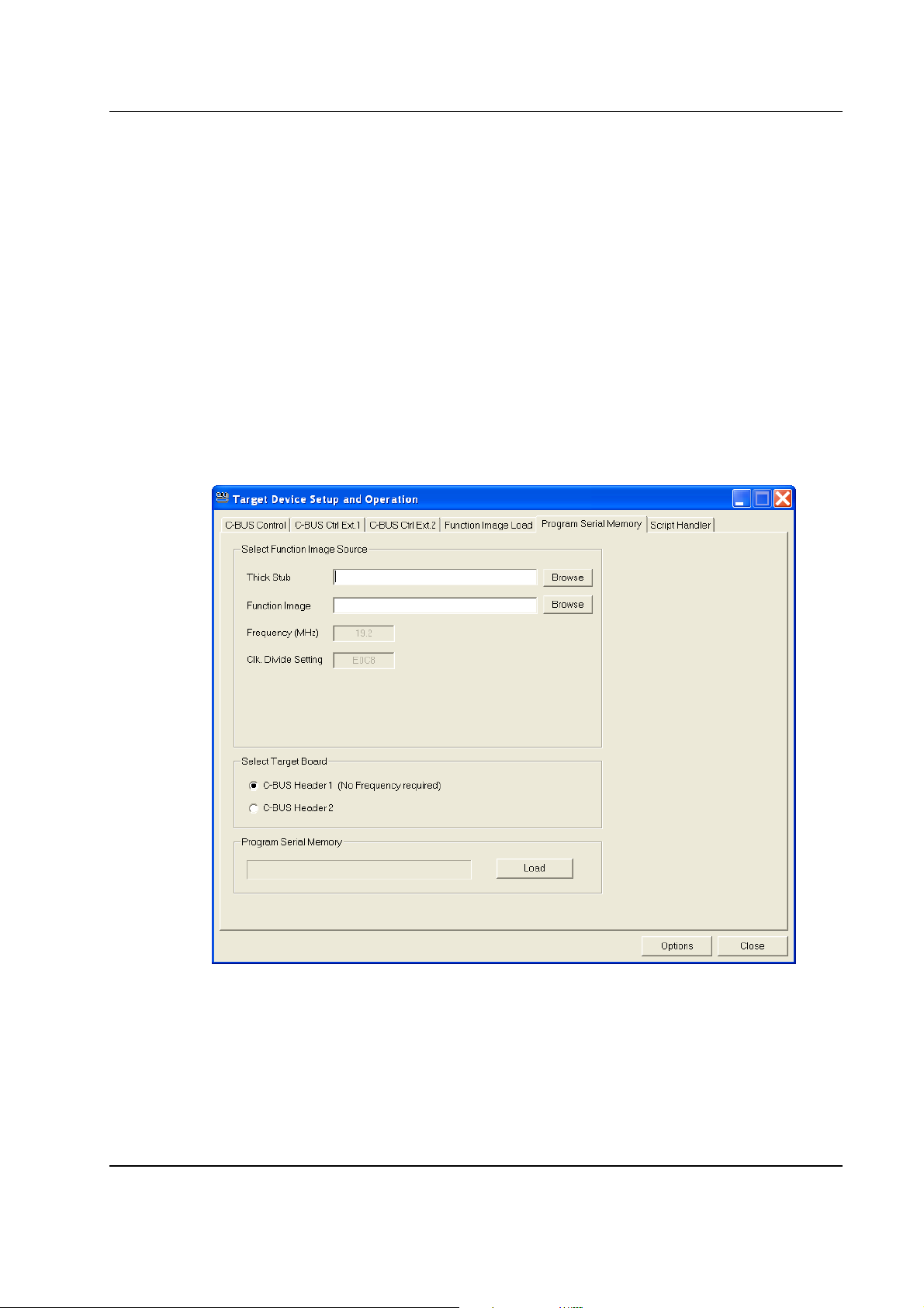
6.3.3 Program Serial Memory
The serial memory device fitted to the PE0601 is a Numonyx or ST M25P10A 1Mbit SPI serial
Flash or equivalent. Loading a FI into this serial memory requires a "thick stub" application programme
EF0601_M25P10_10_xxxx.h (
o
version), where ‘xxxx’ is the ‘xxxx’ element of
r later
PE0601-xxxx. For example, if using a PE0601-7163, then the thick stub programme to use is
EF0601_M25P10_10_7163.h. The thick stub programme is available from the CML website.
Use the ‘Program Serial Memory’ tab:
• Enter the name of the file containing the thick stub (EF0601_M25P10_10_xxxx.h), or
navigate to the required file using the ‘Browse’ button. This file is in the same ‘C’ language
header format as the Function Image™.
• Enter the name of the file containing the Function Image™, or navigate to the required file
using the ‘Browse’ button.
• Select target board.
• Click the ‘Load’ button.
Figure 7 – Program Serial Memory Tab
Shortly after pressing the ‘Load’ button, a message box will confirm that the application has
loaded the Thick Stub.
© 2011 CML Microsystems Plc 28 UM0601/2

Evaluation Kit for CMX7x6x PE0601-xxxx
Figure 8 – Thick Stub Loaded Message Box
Click on the message box ‘OK’ button and the application will proceed to programme the Function
Image™ into the serial memory on the PE0601 card. Progress is shown visually on the progress
bar. When programming is complete a message box will be displayed indicating if the operation
was successful or not.
Figure 9 – Program Serial Memory Complete Message Box
© 2011 CML Microsystems Plc 29 UM0601/2

Evaluation Kit for CMX7x6x PE0601-xxxx
6.4 Troubleshooting
© 2011 CML Microsystems Plc 30 UM0601/2

Evaluation Kit for CMX7x6x PE0601-xxxx
7 Performance Specification
7.1 Electrical Performance
7.1.1 Absolute Maximum Ratings
Exceeding these maximum ratings can result in damage to the evaluation kit.
Min.
Supply (+V – 0V) -0.3 9.0 V
Supply (-V – 0V) 0.3 -9.0 V
Voltage on any connector pin to V
Current into or out of +V and V
-0.3 3.6 V
SS
pins 0 +0.45 A
SS
Current into or out of any other connector pin -20 +20 mA
7.1.2 Operating Limits
Correct operation of the Evaluation Kit outside these limits is not implied.
Notes
Min. Max. Units
Supply (+V – 0V) 4.5 5.5 V
Supply (-V – 0V) -4.5 -5.5 V
External Clock Frequency 3.0 24.576 MHz
Max. Units
© 2011 CML Microsystems Plc 31 UM0601/2

Evaluation Kit for CMX7x6x PE0601-xxxx
7.1.3 Operating Characteristics
For the following conditions unless otherwise specified:
Evaluation device clock frequency = 19.2MHz, +V
= 5.0V, Tamb = +25°C.
For CMX7x6x parameters, see relevant CMX7x6x datasheet.
Notes Min. Typ. Max. Units
DC Parameters
IDD 1, 2 - 60 - mA
1, 2 - -30 - mA
- I
DD
+3V3A 3.15 3.3 3.45 V
+3V3D 3.15 3.3 3.45 V
+3V3SPKR 3.15 3.3 3.45 V
+1V8_CORE 1.70 1.8 1.85 V
+4V0 3.82 4.0 4.18 V
-4V0 -3.82 -4.0 -4.18 V
Analogue Parameters
Output Impedances
I/Q_OUTP/N 3 - 22 -
kΩ
Speaker 1 4
Speaker 2 4
Input Impedances
IP1 and IP2 - 50 -
kΩ
I/Q_INP/N 4
I/Q_IN - 5 -
External Clock Input
kΩ
'High' Pulse Width 21 - - ns
'Low' Pulse Width 21 - - ns
Input Impedance 10 - -
MΩ
Notes:
1. PCB current consumption. Not the current consumption of the CMX7x6x.
2. Not including any current drawn from pins by external circuitry.
3. Small signal impedance.
4. CMX7x6x parameter, see relevant CMX7x6x datasheet.
© 2011 CML Microsystems Plc 32 UM0601/2

Evaluation Kit for CMX7x6x PE0601-xxxx
7.1.4 Operating Characteristics - Timing Diagrams
Please refer to relevant CMX7x6x datasheet for details.
© 2011 CML Microsystems Plc 33 UM0601/2

Evaluation Kit for CMX7x6x PE0601-xxxx
About FirmASIC®
CML’s proprietary FirmASIC® component technology reduces cost, time to market and development risk,
with increased flexibility for the designer and end application. FirmASIC® combines Analogue, Digital,
Firmware and Memory technologies in a single silicon platform that can be focused to deliver the right
feature mix, performance and price for a target application family. Specific functions of a FirmASIC®
device are determined by uploading its Function Image™ during device initialization. New function
images may be later provided to supplement and enhance device functions, expanding or modifying endproduct features without the need for expensive and time-consuming design changes. FirmASIC®
devices provide significant time to market and commercial benefits over Custom ASIC, Structured ASIC,
FPGA and DSP solutions. They may also be exclusively customised where security or intellectual
property issues prevent the use of Application Specific Standard Products (ASSP’s).
CML does not assume any responsibility for the use of any circuitry described. No IPR or circuit patent licences are implied.
CML reserves the right at any time without notice to change the said circuitry and any part of this product specification.
Evaluation kits and demonstration boards are supplied for the sole purpose of demonstrating the operation of CML products
and are supplied without warranty. They are intended for use in a laboratory environment only and are not for re-sale, enduse or incorporation into other equipments. Operation of these kits and boards outside a laboratory environment is not
permitted within the European Community. All software/firmware is supplied "as is" and is without warranty. It forms part of
the product supplied and is licensed for use only with this product, for the purpose of demonstrating the operation of CML
products. Whilst all reasonable efforts are made to ensure that software/firmware contained in this product is virus free, CML
accepts no responsibility whatsoever for any contamination which results from using this product and the onus for checking
that the software/firmware is virus free is placed on the purchaser of this evaluation kit or development board.
 Loading...