

Page 1

Workstation Console
Owner’s Manual
http://www.cmlabs.net
Page 2
Greetings
Friends,
Thank you very much for
buying MotorMate ! MotorMate is the result of many
hundreds of hours of design
and engineering, and we
hope that you will be pleased
with it. You will find that
MotorMate has many unique
features and it will quickly
become the central focus of
your control room.
Thanks for your support.
Kindest regards,
Carl Malone
President
CM Labs
Product Warranty
CM Labs shall not be liable for loss of use of the
product or other incidental or consequential costs,
expenses or damages incurred by the consumer or
any other user. Some states do not allow the exclusion
or limitation of implied warranties or consequential
damages, so the above limitations or exclusions may
not apply to you.
Legal Remedies: This warranty gives you specific legal
rights and you may also have other rights that vary from
state to state.
Warranty Performance: During the above one (1) year
warranty period, your defective product will either be
repaired or replaced with a reconditioned model of an
equivalent quality (at CM Labs sole option) when the
product is returned, postage prepaid, to CM Labs. The
warranty of the repaired or replacement unit will-continue
for the warranty of the original unit or six (6) months,
whichever is longer. Other than the postage requirement,
no charge will be made for such repair and/or replacement. CM Labs strongly recommends that you insure the
product for full value prior to mailing it. You must contact
CM Labs to obtain a return authorization (RA#) number
prior to returning the unit. No Merchandise will be accepted without the RA# clearly displayed on the package.
This CM Labs electronic product warranty extends only to
the original purchaser and user of the product and is
applicable in the United States of America only.
Warranty Duration: This CM Labs electronic product is
warranted to the original purchaser for a period of one (1)
year from the original purchase date.
You must contact CM Labs ([email protected]) to
obtain a return authorization (RA#) number prior to
returning the unit. No Merchandise will be accepted
without the RA# clearly displayed on the package.
Include valid proof of purchase (sales receipt) identifying the model purchased, date of purchase and your
daytime telephone number.
Warranty Coverage: This CM Labs electronic product is
warranted against defective materials and construction.
This warranty is void if the product has been damaged by
accident or unreasonable use, neglect, improper service,
or other causes not arising out of defects in materials or
construction.
Warranty Disclaimers: Any implied warranties arising
from this sale, including, but not limited to, the implied
warranties of merchantability and fitness for a particular purpose, are limited in duration to the above one
year period.
Software: Software is licensed, not sold. CM Labs and its
licensors do not warrant that the software will be free
from errors or meet your specific requirements. All
software is provided “As Is.”
Copyright: The software and any documentation supplied with this product are protected by copyright.
Notice: Please return your warranty card immediately.
Your name will be placed on our mailing list (unless you
request otherwise) and we will inform you of all product
updates as well as new product developments. Some of
these updates will be free, so please return the card.
CM Labs reserves the right to make improvements or
changes at any time to the products described in this
manual.
Published by: CM Labs
13221 191st Ave. S.E.
Monroe, WA 98272
U.S.A.
Version 1.0 2004
Copyright © 2004 CM Labs™
All rights reserved
Page 2 CM Labs MotorMate Owner’s Manual
Page 3

Installation and Connections
Table of Contents
MIDI Connections ............................................ 6
RS-232 Port Connection .................................. 6
Audio Connections .......................................... 6
Computer Setup .............................................. 6
Macintosh AMS Setup ..................................... 6
Windows XP Setup .......................................... 6
ProTools Setup ................................................ 7
Digital Performer Setup ................................... 7
Steinberg Cubase Setup .................................. 7
Steinberg Nuendo Setup .................................. 7
Multiple Unit Configurations ............................. 8
Parallel Combo Connections ............................ 8
Troubleshooting ............................................... 8
Multi Unit Assembly ......................................... 9
Operations: Mixer Controls
Upper and Lower Panel Uses ..........................11
LCD Display and SELECT Switches .............. 12
LCD Top Row ................................................ 12
DAW Use .......................................... 12
SixtyFour Use ................................... 12
MP-8 Use .......................................... 12
LCD Bottom Row ........................................... 12
DAW Use .......................................... 12
SixtyFour Use ................................... 12
MP-8 Use .......................................... 12
Using the View Stick and the Zoom Stick ....... 12
Channel Level Meters .................................... 13
Channel SELECT Switches ........................... 13
Channel SELECTs and DAW functions ........ 13
Other SELECT Switch Uses .......................... 13
PLUG-IN Operations ...................................... 16
Insert Control .................................... 16
Parameter Control ............................. 16
Plug-in Bypass .................................. 16
Plug-in Channel Select ...................... 16
Assigning Plug-ins ............................ 17
Other MULTI Switch Functions ...................... 17
Audition ............................................ 17
Pre Roll ............................................ 17
In ...................................................... 17
Out ................................................... 17
Post Roll ........................................... 17
Punch .. ............................................ 17
Loop ................................................. 17
Suspend ........................................... 17
The BURN Section ........................................ 18
Record Operations ............................ 18
Record Safe ...................................... 18
Selecting Automation Modes (1)......... 18
Selecting Automation Modes (2) ....... 18
Using Automation Modes .................. 18
Automation Enables ......................... 19
Automation Suspend ......................... 19
MUTE and SOLO .......................................... 20
Solo Safe .......................................... 20
Faders ........................................................... 20
Setting Mix Levels ............................. 20
Setting Aux Levels with Faders .......... 20
Viewing Fader Levels in dB ............... 20
Defaulting Faders to Unity ................. 20
Operations: Transport Controls
View Control Section ..................................... 13
Group Switch Operations .................. 13
Create Groups .................................. 13
Suspend Groups ............................... 14
Query Groups ................................... 14
Rotary Pots and Controls ............................... 14
Pan and Stereo Balance .................... 14
Defaulting Pans to Center.................. 14
Selecting Aux Sends ......................... 14
Flipping Sends to Faders.................... 14
Send Mutes ........................................14
Send Pre/Post ....................................14
Defaulting Sends to Unity .................. 15
Send Buss Assignment ..................... 15
Channel IN/OUT Assignment ............15
Time Code Display ........................................ 21
Transport Switches ........................................ 21
Adding Locate Points to Memory .................... 21
Next and Last Locate ..................................... 21
Locate Mode .................................................. 21
Enter Pre Roll, In, Out, or Post Roll (1) ........... 21
Enter Pre Roll, In, Out, or Post Roll (2) ........... 22
Entering Values into the Big Counter .............. 22
Scrub and Shuttle Controls ............................ 22
Scrub ................................................ 22
Fine Scrubbing .................................. 22
Shuttle .............................................. 22
CM Labs MotorMate Owner’s Manual Page 3
Page 4

Table of Contents (continued)
Operations: Edit and System Controls
Zoom and Navigator Section .......................... 23
Zoom Stick ........................................ 23
Track and Time Navigator Switches ............... 23
Navigate Mode .................................. 23
Adjust Mode ...................................... 23
Adjust Region Start ........................... 23
Adjust Region End ............................ 23
Clipboard Switches ........................................ 23
CUT .................................................. 23
COPY ............................................... 23
PASTE .............................................. 23
DELETE ............................................ 23
MODE ............................................... 24
TOOL ............................................... 24
CAPTURE ........................................ 24
SEPARATE ...................................... 24
System Controls ............................................ 25
SHIFT ............................................... 25
UNDO ............................................... 25
SAVE ................................................ 25
DEFAULT ......................................... 25
BYPASS ........................................... 25
ALL ................................................... 25
ALT/FINE .......................................... 25
WINDOW .......................................... 25
TOOLS ............................................. 25
PLUG IN ........................................... 25
COMPARE ....................................... 25
SUSPEND ........................................ 26
CREATE ........................................... 26
ENABLE ........................................... 26
MODE ............................................... 26
Reset MotorMate ............................... 26
ESC .................................................. 26
ENTER ............................................. 26
UTILITY ............................................ 26
ON LINE ........................................... 26
ASSIGN ............................................ 26
MIDI .................................................. 26
CONFIGURE .................................... 26
AUDITION ........................................ 26
STATUS ........................................... 27
LOOP ............................................... 27
MONITOR ........................................ 27
PUNCH ............................................. 27
END .................................................. 27
LOCATE ........................................... 27
Return To Zero .................................. 27
Monitor Section ............................................. 27
Appendix A
Controlling the SixtyFour from MotorMate
Installation and Connections .......................... 28
RS-232 Connections ......................... 28
Audio Connections ............................ 28
Mono Connections ............................ 29
Stereo Connections ........................... 29
Surround Connections ...................... 29
Operations Overview ..................................... 29
Accessing the SixtyFours .................. 29
Creating LCD Channel Labels ........................ 30
Mono Source and Destination Labels ............. 30
Stereo Source and Destination Labels ........... 30
Surround Destination Labels........................... 30
Memory Operations ....................................... 31
Recall ............................................... 31
Save ................................................. 31
Undo ................................................. 31
Source Controls ............................................. 32
Selection Operations ......................... 32
Mono Source Selection ......... 32
Stereo Source Selection ....... 32
Level Control Operations.................... 32
Setting Source Levels ........... 32
Set Level to Unity ................. 32
Set Level to Off .................... 32
Destination Controls ...................................... 32
Routing Operations............................ 32
Routing Mono to Mono .......... 32
Routing Mono to Stereo ........ 32
Routing Stereo to Stereo ....... 32
Cross - Routing Stereo .......... 32
Surround Routing .................. 32
Level Control Operations.................... 32
Destination Levels ................ 32
Stereo Balance .................... 32
Set Level to Unity ................. 32
Set Level to Off .................... 32
Setting Surround Levels ........ 32
Surround Channel Offsets ..... 32
Page 4 CM Labs MotorMate Owner’s Manual
Page 5
Installation and Connections
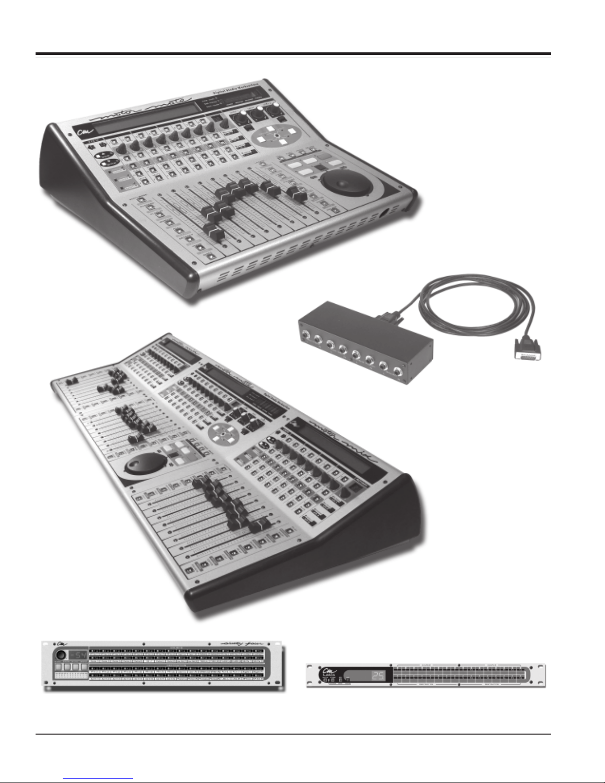
MotorMate
Monitor Interface Module
SixtyFour MP-8
CM Labs MotorMate Owner’s Manual Page 5
Page 6

Installation and Connections
MIDI Connections
Connect the MIDI output of MotorMate to a MIDI input
port on your MIDI interface. Connect the MIDI output of
the same port to the MIDI input on MotorMate. Make a
note of the port number you used. If your MIDI interface
has MIDI activity indicators for its ports, rotate the
MotorMate Jog wheel, and you should see the MIDI input
activity light on the port connected to MotorMate. If this
does not happen, check your connection or cables.
RS-232 Port Connections (Optional)
Connect the RS-232 connector on MotorMate to either a
CM Labs SixtyFour Studio Router or an MP-8 Eight
Channel Mic Preamp. This allows MotorMate to control
all the features in those products.
Audio Connections
Monitor Interface Module (MIM)
Connect both MIM Control Room (Speaker 1) outputs to
your main Control Room amp inputs. Connect both MIM
Studio outputs (Speaker 2) to your main Studio amp
inputs or to a second set of Control Room speakers, or
use these outputs to feed a headphone distribution
system. All the inputs and outputs are balanced, so we
recommend using TRS type cables for interconnect.
Computer Setup
Apple OSX Audio MIDI Set Up
Step 1.) Install your MIDI interface as per the installation
directions of the MIDI interface manufacturer. Make a
note of which MIDI port you connected MotorMate to on
your interface.
Step 2.) Open the Apple Audio MIDI Setup (AMS). Click
on the MIDI Devices tab.
Step 3.) Click on the Add Device icon. In the Device
Name box type MotorMate. Scroll down the Manufacturer
list and select CM AUTOmation (our former name). Click
on the box beside Model and select “MotorMix”. (Since
MotorMate uses the same type of MIDI protocols as
MotorMix).
Connect the Monitor Interface Module (or MIM for short)
to MotorMate using the 15 pin D-Sub cable supplied with
your MotorMate.
to MotorMate
DAW Mix
Outputs
2 Track,
CD Player,
Sound Card
Control Room
Speakers
Studio, Aux
Speakers or
Headphone
Amp
Connect your left and right workstation audio outputs to
the MIX Inputs on the MIM. Connect your 2 Track, CD
player Sound Card ,or other device to the Aux Inputs on
the MIM. The Mix and Aux inputs are added together
before being sent into the monitor controls on
MotorMate.
Page 6 CM Labs MotorMate Owner’s Manual
Step 4.) Select Transmit Channel 1. Select Receive
Channel 1.
Step 5.) Click on “OK”. If a warning message appears
complaining about having same device ID’s, click on that
box’s OK.
Step 6.) Then connect the virtual cables on the MotorMate icon to corresponding MIDI port on the MIDI interface icon.
Step 7). Close AMS.
Windows XP Set Up
Install your MIDI interface as per the installation directions of the MIDI interface manufacturer. Make a note of
which MIDI port you connected MotorMate to on your
interface.
Page 7

Installation and Connections
Pro Tools Setup
Step 1.) Open a Pro Tools session and click on the
“Setups” tab. Open the “Peripherals” menu and click on
the MIDI Controllers tab.
Step 2.) Click on the small box just below “Type” and
select “MotorMix”. Since MotorMate uses the MotorMix
personality file already in ProTools, no special file is
needed.
Step 3.) Click on the small box just below “Receive From”
and select the MotorMate cable input.
Step 4.) Click on the small box just below “Send To” and
select the MotorMate cable output. At this point, the small
box under “# Ch’s” should show “8”.
Step 5.) Click on the “OK” box in the “Peripherals” menu.
Step 6.) If you are using Pro Tools 5.1, click on the MIDI
tab and select “Input Devices”. Click on the MotorMate
listed. This will enable Pro Tools to receive its MIDI input.
Step 7.) In Pro Tools 5.1 and higher, go to the Set up
window and choose Preferences. In the Preferences box,
click on Operation. Then select ‘Classic’ located in the
Numeric Keypad Mode Section. Classic Numeric Keypad
allows you use the Locate function on MotorMix.
Step 6.) In the “ MIDI Communication:” box select
“MotorMate” or whatever name you have used to define it
in your MIDI device setup. Click “OK” and you’ll be up
and running.
Note: CM Labs maintains the MotorMix plug-in for Digital
Performer. Please check our website for updates to the
Plug-in.
Steinberg Cubase Setup
Step 1.) Launch Cubase and click on the Devices menu.
Click on Device Setup.
Step 2.) Click on Add/Remove, then select Mackie HUI in
the Device Classes list. Click on Add. Then Click O.K.
Step 3.) Click on the Devices menu. Click on Mackie HUI
in the Device Classes list. Then select the proper MIDI
Input and MIDI Output port for MotorMate. Then click
O.K.
Steinberg Nuendo Setup
Step 1.) Launch Cubase and click on the Devices menu.
Click on Device Setup.
Step2.) Click on Add/Remove, then select Mackie HUI in
the Device Classes list. Click on Add. Then Click O.K.
Step 8.) Press the PLAY switch on MotorMate, the
session will start to play and the Time Code display on
MotorMate will show the play time.
Step 9.) Each time you use Pro Tools you should have
MotorMate powered up first to insure that it gets a
complete update of your most recent session settings.
Digital Performer Software Setup
Step 1.) Log on to http://www.cmlabs.net and open the
MotorMix page. Click on the Digital Performer link and
follow the download instructions there.
Step 2.) Expand the MotorMix archive.
Step 3.) Put the MotorMix Plug-in into your DP Plug-ins
folder.
Step 4.) Reboot your Mac and launch Digital performer.
Step 5.) Pull down the “Basics” menu and select “Control
Surface Setup” and select MotorMix in the Hardware box.
(Since MotorMate uses the same MIDI protocols as
MotorMix).
Step 3.) Click on the Devices menu. Click on Mackie HUI
in the Device Classes list. Then select the proper MIDI
Input and MIDI Output port for MotorMate. Then click
O.K.
CM Labs MotorMate Owner’s Manual Page 7
Page 8
Installation and Connections
Multiple Unit Configurations
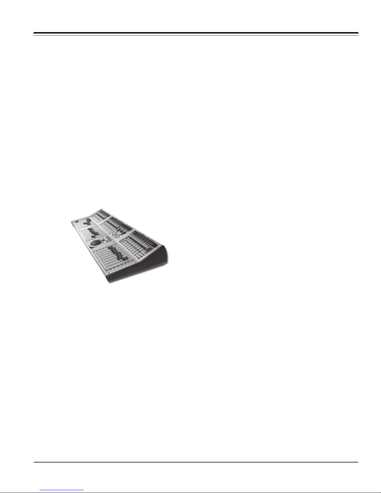
Multiple units will control the mixer by 16, 24, or 32
channels at a time. MotorMate will control the lower 8
channels in a bank, and MotorMix will control the remaining channels in the bank of 16, 24, or 32. View switching
will be 16, 24, or 32 channels wide. View changes can be
done from either MotorMate or MotorMix. Plug-in control
is done entirely from MotorMate.
Connections
Connect MotorMate to your MIDI interface with both MIDI
cables and MotorMix with both MIDI cables to another
MIDI port on your interface.
Multiple units act as separate MIDI devices. The Motor-
Mate and MotorMixes each must be set up identically in
your MIDI device definitions except for the device names
you use. In ProTools or Digital Performer, set up the
MotorMix as an additional MIDI controller. MotorMate
must remain first in the controller list.
Fader Position:
Move the faders from bottom to top and upper row of the
LCD display will display fader position from 000 to 255.
Rotary Pots:
Rotate the rotary pots, and the motorized faders should
move up and down.
Switches and LED’s:
Press each MotorMate switch and its associated LED
should lite, and the Time Code display should light when
the switch is down.
View and Zoom sticks:
Push either stick in all 4 directions (left-right and updown). The associated LED’s will light (along with the
Time Code LED’s) to indicate which direction you are
pushing.
Push either stick in. All of the associated LED’s will light
(along with the Time Code LED’s).
Jog Wheel:
Rotate the Jog Wheel clockwise and the lower row of the
LCD will show “Forward SS PP” where SS is the speed
you are rotating the wheel, and PP is the absolute
position of the wheel. The position should go from 00 to
3F.
If you wish to physically connect MotorMate and MotorMix together, see page 9.
Troubleshooting
Problems can occur in 3 areas.
1.) MotorMate
MotorMate Final Test
Using a known good MIDI cable, simply connect the
MotorMate MIDI output directly into the MIDI input on
MotorMate. Press and hold the ENTER and ESC
switches on MotorMate and apply power. MotorMate will
enter Final Test mode.
MIDI:
With a MIDI cable connected from MIDI IN to MIDI OUT
there should be a capital m (M) appear just to the right of
the word “Test” on the lower row of the LCD.
Fader Touch:
Touch each MotorMate fader knob. The channel LED’s
and Time Code LED’s should light.
Page 8 CM Labs MotorMate Owner’s Manual
Rotate the Jog Wheel counter clockwise and the lower
row of the LCD will show “Backward SS PP” where SS is
the speed you are rotating the wheel, and PP is the
absolute position of the wheel. The position should go
from 3F to 00.
If the self test fails, then contact CM Labs at
[email protected].
2.) The MIDI interface must talk to the computer operating system. If your MIDI interface installation disk includes a diagnostic program, run that to check the
integrity of the interface and its communication with the
operating system. If you can successfully run a diagnostic program, then proceed to step 3 below.
If it does not have a diagnostic, or the diagnostic fails,
consult the manufacturer of the interface.
3.) The computer operating system must talk with the
DAW application. Recheck all the MIDI setup settings
you made in Windows, Free MIDI, or the Apple OSX
AMS setup. If these steps are in order, then recheck the
software setups.
Page 9
Installation and Connections
Multiple Unit Assembly
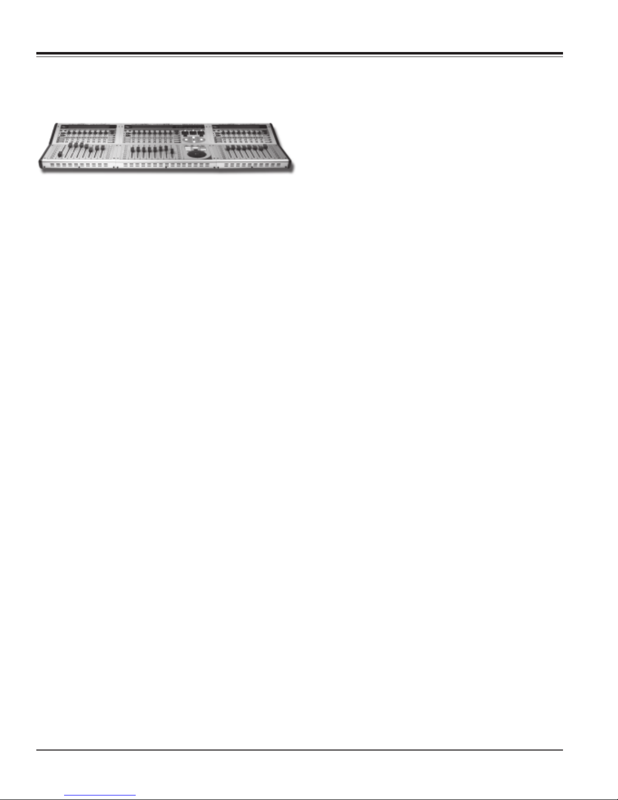
MotorMate and MotorMix units can be physically connected to each other to create a single larger console.
You may connect MotorMate and as many as 3
MotorMixes together to create a 32 channel console.
Tools required
1.) #4 Phillips head screwdriver.
2.) 1/16” Allen wrench or driver.
Parts Required
1.) 4 pieces 4-40 x 3/8” Phillips head screws (per unit).
2.) 4 pieces 4-40 Nut with captive lock washers (per unit).
Preparation
1.) Remove power cables from all units.
2.) Remove any other cables connected to the units.
Top Cover Removal
1.) Remove 6 Phillips head screws on front and rear of
chassis on all Motor Mix units.
2.) Remove 6 Allen Panhead screws from top of all Motor
Mix units.
3.) Turn the MotorMix units so the back sides (power
entry side) are facing you.
4.) Lift up the rear of the top cover about 2 inches and
rest it on the ledge provided inside.
5.) Raise the rear cover up about 2 inches more with one
hand. With your free hand disconnect the 2 cables
plugged in to the Power Module in the chassis bottom.
Rest the chassis top back on the inside ledge.
6.) Reach your arm over Motor Mix and grab the chassis
at the front (near the faders). With your other hand, lift the
Top Cover off of the ledge about 3 inches. Push forward
and lift the top cover free. Set the Top Covers aside.
Don’t worry about keeping track of which top goes with
which bottom.
Side Cheek Removal
If you are joining 2 units, you must remove a Left Side
panel from one, and the Right Side panel from the other.
If you are joining 3 or more units, you must remove a Left
Side Cheek from one, and the Right Side panel from
another, and both Side panels from the remaining Motor
Mix units.
Connecting chassis bottoms
1.) Position the Chassis Bottoms side by side just as they
will be connected together. Don’t worry about keeping
track of which bottom goes with which top. Insert four 440 machine screws between each chassis bottom and
finger tighten the nuts.
2.) Check and adjust the alignment between the Chassis
Bottoms, and tighten the 4-40 screws.
Re-Fitting Top Covers
1.) Position the Chassis Bottom assembly so the Power
Modules side face you.
2.) Move a Top Cover into position over one end of the
chassis bottom assembly. Position Top Cover at about a
45 degree angle with the rear side high. Slip Top Cover at
fader side over edge of Chassis Bottom and lower rear
side down to rest on ledge of Chassis Bottom.
4.) Lift the Top Cover slightly at rear and reach inside and
plug in the Power Module Cables. Note: The locking tabs
on the connectors go towards the center of the Power
Module.
IMPORTANT NOTE: PLEASE DOUBLE CHECK
THAT THESE CONNECTORS ARE NOT OFF BY A
PIN. IF THEY ARE CONNECTED IMPROPERLY,
SEVERE AND WIDESPREAD DAMAGE WILL RESULT WHEN POWER IS APPLIED.
5.) Lower the Top Cover completely while checking for
binding wires inside along the top.
6.) Repeat steps 1 - 5 above for remaining units without
forcing the Top Covers fully down. When lowering the
remaining tops into final position they may become tight
at the top edge. Lift the entire assembly at the center and
they should drop into place.
Securing Top Covers
1.) Install the (3) #4 Black Phillips sheet metal screws
into each chassis rear but do not tighten.
2.) Install the (6) 4-40 Black Allen screws into each Top
Cover but do not tighten.
3.) Install the (9) #4 Black Panhead Phillips sheet metal
screws into each chassis front but do not tighten.
4.) Check and adjust the alignment between the Chassis
Bottoms, and tighten the 4-40 Black Allen screws.
5.) Tighten all remaining screws.
6.) Turn Power Switches off on all units and connect
power cables.
7.) Power on a unit and check for proper power up cycle.
Repeat for all units. Note that the LCD contrast controls
should be adjusted until all units have same contrast.
CM Labs MotorMate Owner’s Manual Page 9
Page 10
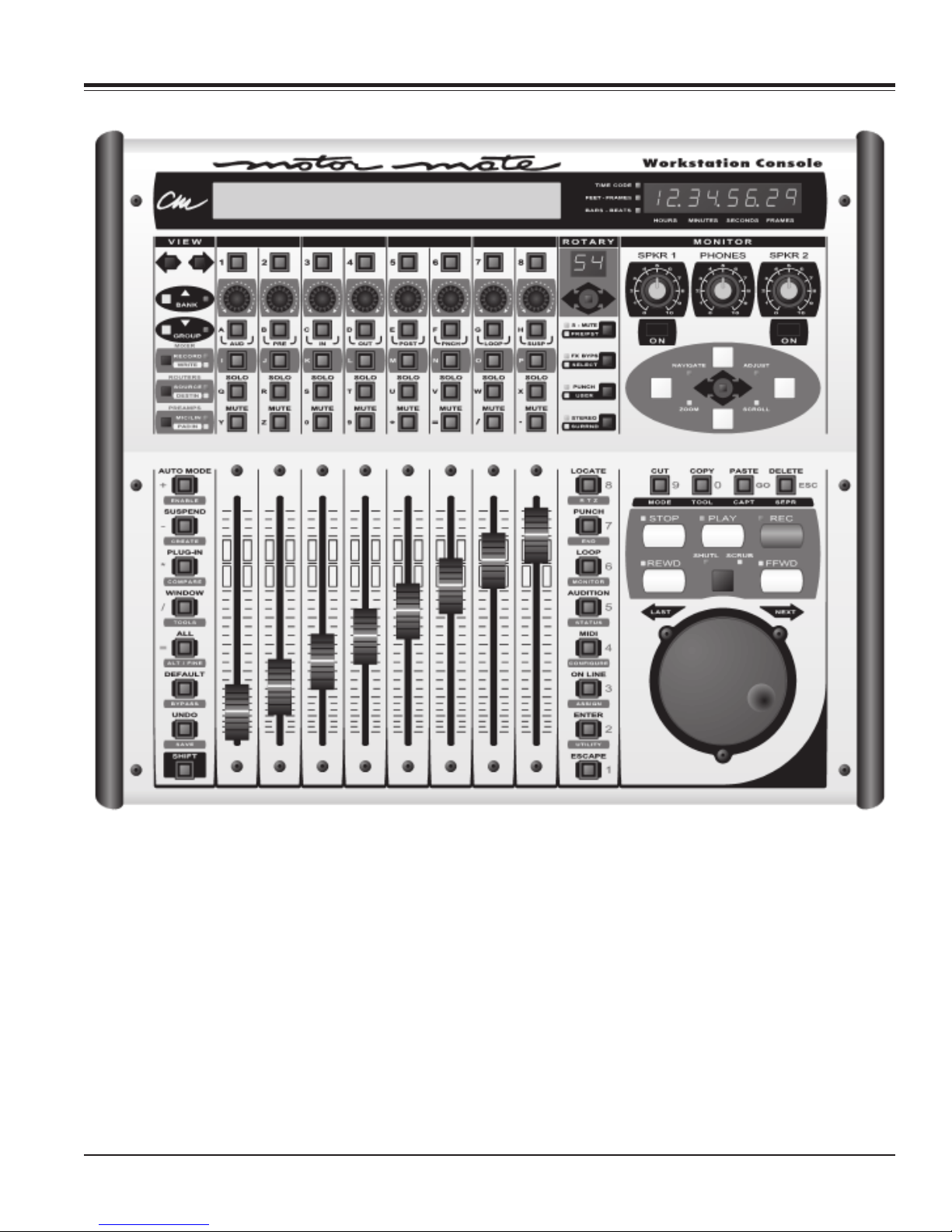
Operations
The MotorMate operations and features described in this manual are detailed to
describe its operations primarily with ProTools from Digidesign. Although MotorMate
operates with several other DAW platforms, some of the features described in this
manual operate differently or are not implemented in other software as of this date.
If there are features described in this manual that you would like to see implemented
in other software, please contact us at [email protected], and we will forward
that information to the software company. With enough input from our customers, it is
very possible to continue to increase support.
Thank you for your patience.
Page 10 CM Labs MotorMate Owner’s Manual
Page 11
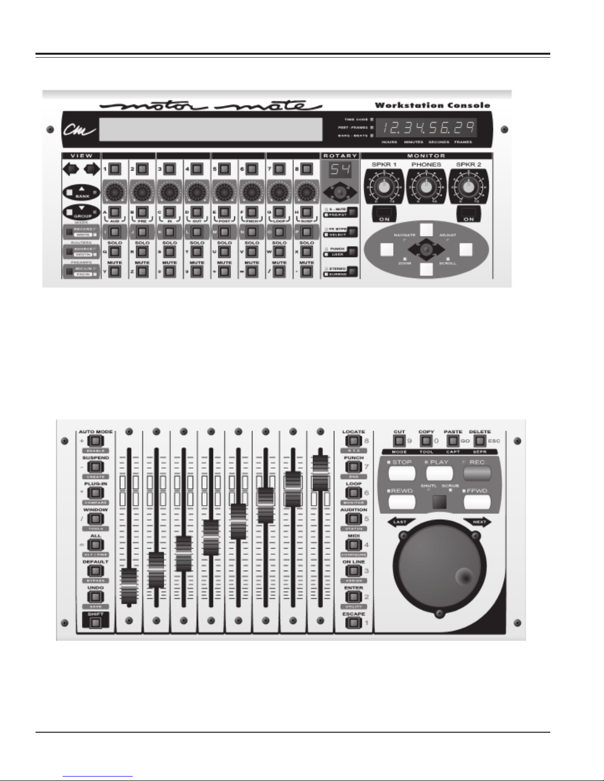
Upper and Lower Panels
MotorMate Upper Panel
The MotorMate Upper Panel is the control surface for many of the mixer functions on all the session channels or
tracks. From this panel, you will control the pans, sends, plug-in’s, mutes, solos, record readies, grouping functions,
automation modes, automation enables, timecode display and meters. Additionally this panel has the waveform
navigator section and operates the stereo monitor section inside MotorMate and surround monitoring by connecting a
CM Labs SixtyFour Studio Router. The SixtyFour and the CM Labs MP-8 Mic Preamps are also controlled from the
upper panel of MotorMate. The LCD display is indispensable. It shows all track names, parameter settings and
operator messages.
MotorMate Lower Panel
The MotorMate Lower Panel has the motorized touch sensitive faders and is the work surface for all the transport and
editing functions. From this panel, you access the autolocator and the next and last locate switches. The modifier
switches expand the functions of both the Upper and Lower Panels of MotorMate. The Clipboard Controls, in
conjunction with the Navigator section on the upper panel, provide complete control of all waveform editing. The
Save and Undo switches control the session file. Finally, the high resolution precision Jog/Shuttle wheel and related
controls provide rapid and very fine control of edit regions and punch in/out points.
CM Labs MotorMate Owner’s Manual Page 11
Page 12
Mixer Controls
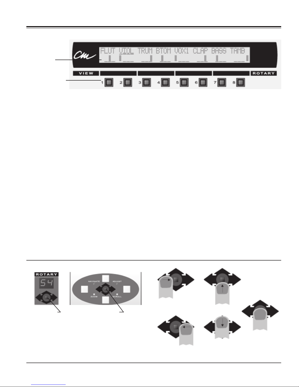
LCD Display and channel SELECT Switches
LCD Display
SELECT switches
LCD Top Row
Top Row Use for DAW Application
1.) A shortened version (4 characters) of your channel
labels.
2.) Plug-in switch parameter names and states (text).
3.) Special uses of channel SELECT switches.
4.) Menu pop ups from the computer.
5.) Input/Output and Send Buss Assignments.
Top Row Use for CM Labs SixtyFour studio router
1.) A shortened version (4 characters) of the source and
destination labels you entered into the SixtyFour from
MotorMate.
2.) The current SixtyFour memory name you entered into
the SixtyFour from MotorMate.
Top Row Use for Surround Monitoring
1.) “*Master* *Center* *Surround* *Sub* “ speaker
labels.
2.) “Left&Rght *Center* *Surround* *Sub* “ speaker
offsets (when the View Stick is pushed).
Top Row Use for CM Labs MP-8 Mic Preamp
1.) A shortened version (4 characters) of the mic preamp
labels you entered into the MP-8 from MotorMate.
LCD Bottom Row
Bottom Row Use for DAW Application
1.) Channel pan (or pan right for stereo channels) position (graphically).
2.) Channel send level (graphically).
3.) Channel send pre/post state (text).
4.) Send buss assignment.
5.) Plug-in continuous parameter names (text) and
settings (numeric).
6.) Channel automation mode (text).
7.) Group ID.
8.) Channel input/output assignment.
Bottom Row Use for Surround Monitoring
1.) Overall surround speaker level (text).
2.) L*R speaker offset level (text).
3.) Center speaker offset level (text).
4.) L*R surround speaker offset level (text)
5.) Subwoofer speaker offset levels (text).
Bottom Row Use for CM Labs SixtyFour studio router
1.) Source and destination levels in dB (text).
Bottom Row Use for CM Labs MP-8 Mic Preamp
1.) Mic preamp gain setting in dB (text).
Using the View Stick and the Zoom Stick
View Stick Zoom Stick
These sticks have 5 “directions of motion” and you can
move them left, right, up, down and in. It is important
where you place your finger to operate them and how you
make your movements to achieve the greatest degree of
control. For horizontal and vertical movements, touch the
black arrows around the side of the stick, and move your
finger sideways or up/down. To push in the View Stick,
place your finger on the tip and press in.
Page 12 CM Labs MotorMate Owner’s Manual
RIGHT
UP
IN
DOWN
LEFT
Page 13
Mixer Controls
Channel Level Meters
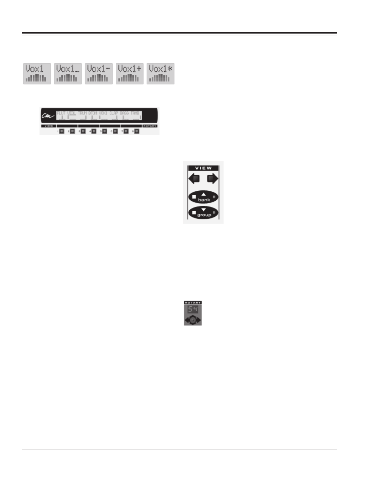
The character to the right of the channel label is used to
display the signal level. There are 5 states for this meter.
OFF -20dB -10dB +0dB +10dB
Channel SELECT Switches
These 8 are the top switch row located just below the
LCD and each one has its own green LED.
Channel SELECT’s and DAW functions
These switches allow the channel strips to be selected
for grouping, deletion, assignment etc. When a channel
SELECT switch is pressed, it lights up to indicate that the
channel is selected. When the MotorMate view is
changed (swapping banks), the originally selected
channel remains selected. Selected channels not in the
current view will remain selected.
Several channels can be also be selected at a time.
There are 2 ways to add or subtract channels to a
selection.
1.) Simply press and hold down one SELECT switch and
tap additional SELECT switches to add or subtract them
from the selection.
2.) Depress the SHIFT key on the MotorMate (or the
keyboard) and tap additional SELECT switches to add or
subtract them from the selection.
To select all channels (not just the ones being viewed by
MotorMate) press and hold down the ALL switch on
MotorMate and press any SELECT switch. Holding
SHIFT and ALL switches on MotorMate, and then a
SELECT switch changes the select state of that channel
and also changes all other channels to the opposite
select state. Pressing a single channel SELECT switch
more than once will not change its state. Hold down the
SHIFT switch and press a single channel SELECT switch
to change its state.
Other SELECT Switch Functions
1.) When the WINDOW switch is held, the SELECT
switches open and close DAW windows as indicated on
the bottom row of the LCD. The SELECT LED’s lit up
indicate that the window is open or foremost.
2.) When the ENABLE switch is down the fader, mute,
pan, send level, send mute and plug-in automation
enables will appear on the bottom row of the LCD. Press
a single channel SELECT switch to change its state.
3.) When in PLUG-IN parameter mode (rotary display
showing “PA”), the SELECT switches/LED’s are used for
plug-in switch control. A lit SELECT LED indicates that
the plug-in switch parameter is on. Pressing that
SELECT switch will toggle the switch parameter off.
4.) When the rotaries are in surround monitor mode (to
enter surround monitor mode, press the switch next to
the yellow “surrnd” LED until it lights) the SELECT
switches will solo the L*R, Center, L*R Surround and Sub
speaker outputs as indicated on the bottom row of the
LCD.
5.) When the lower panel “default” switch is active, the
SELECT switches are used to set faders to unity, their
default values.
View Control Section
The VIEW control section has the Left
and Right Arrow switches, BANK switch
/ LED and the GROUP switch / LED.
If the BANK LED is off, pressing the
Right or Left Arrow switch scrolls the
current view of 8 channels by 1 channel
at a time.
If the BANK LED is on, pressing the Right or Left arrow
switch scrolls the current view of 8 channels by 8
channels at a time. If either of these switches is held
down, it will automatically repeat view changes until the
switch is released.
Press the BANK switch, and the BANK LED will change
state. With the BANK LED lit, view switching is 8
channels at a time, otherwise, it is 1 channel at a time.
Note that moving the View Stick horizontally
exactly duplicates what the Left and Right Arrow
switches do for switching banks.
GROUP switch operations
Create Groups
To create a new group, first use the channel SELECT
switches to select channel to group together. Press and
hold the CTRL switch on the keyboard, and then press
the GROUP switch. This mimics the Command-G from
the keyboard. This will bring up the ProTools Group
dialog box. The next available “free” group appears with
a default name (a, b, c, etc.). Either leave the default
name, overwrite on, or enter a new name from the
keyboard. Press ENTER to complete, or ESC to abort
the process.
CM Labs MotorMate Owner’s Manual Page 13
Page 14
Mixer Controls
Suspend or Enable Groups
Press the GROUP switch, and the GROUP LED will
change. With the GROUP LED lit, the groups are active.
When the GROUP LED is off, the groups are inactive.
Query Groups
To show the Group ID, press and hold down the SHIFT
switch first and then the GROUP switch, and the group
ID will be displayed on the bottom row of the LCD.
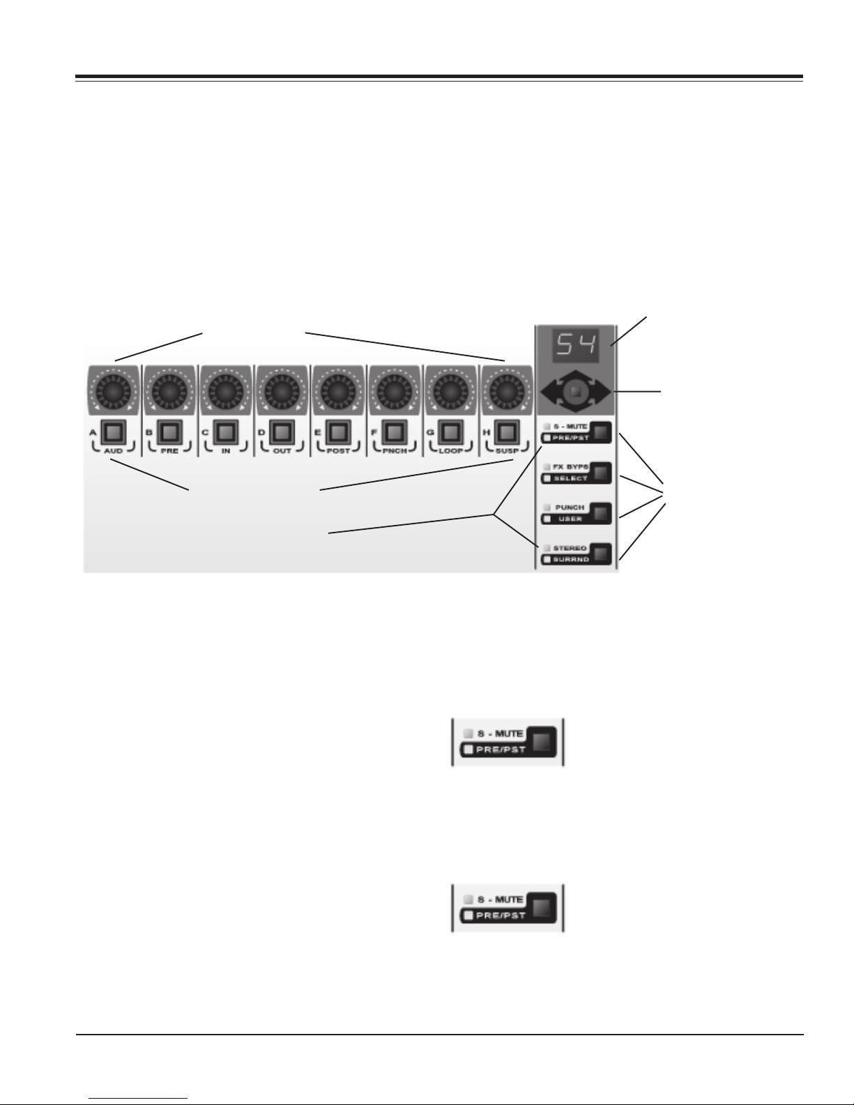
Rotary Pots and Multi Switches
Rotary Pots (8)
MULTI Switches (8)
Selecting Aux Sends
Press the View Stick up, and the Rotary Display will show
“SA” for send A. The bottom row of the LCD will indicate
channel aux level, and the pots then control the settings.
Push the View Stick up, and the Rotary Display will move
to “SB” for send B, “SC” for send C and so on.
When send E is selected, pushing up on the View Stick
will take you back to pan. You can also move from send
A back to pan by pressing down on the View Stick.
Rotary Mode Display
View Stick
Multi Mode Switches
Multi Mode LED’s (8)
This section includes the 8 endless rotary pots, the View
Stick just to the right of the 8 rotaries, and the Rotary
Mode Display. This is a 2 digit, 7 Segment LED character
display. This section also includes the 4 Multi Mode
switches, 8 Multi Mode LED’s, and the 8 MULTI switches
just below the rotary pots.
Controlling Pan and Stereo Balance
When the rotary display shows “P”, the 8 rotaries are
controlling channel pans. The bottom row of the LCD will
indicate channel pan setting. Push in the View Stick, and
the rotary display shows “Pr” to indicate that the rotaries
are controlling channel pan right for stereo channels. If a
channel is not stereo, the LCD lower row will be blank for
that channel.
Defaulting Pans to Center
Press and hold down the DEFAULT switch (third switch
up to the left of the faders) and then press any of the
MULTI switches below the rotaries.
To set all channel pans to center, hold down the ALL
switch (fourth switch up to the left of the faders), then
press and hold down the DEFAULT switch and press any
of the MULTI switches below the rotaries.
Page 14 CM Labs MotorMate Owner’s Manual
Flipping Sends to Faders
Press in on the View Stick, and the sends will be flipped
to the faders to make changes there. Press the View
stick a second time to return.
Send Mutes
The top Multi Mode switch toggles
between S-MUTE and PRE/PST.
When the S-MUTE LED is lit, the 8
MULTI Switches control the send mutes for the currently
displayed send. Pressing any of the 8 MULTI switches
will toggle the state of the send mute. When the LED is
on, the send is muted.
Send Pre/Post
Press the top Multi Mode switch to
toggle the PRE/PST LED on. When
the PRE/PST LED is lit, the 8 MULTI
switches control whether the send on that channel is pre
or post fader. When the LED is lit, the send is pre fader.
Page 15

Mixer Controls
Defaulting Sends to Unity
To quickly set a channel send to unity, press and hold
down the DEFAULT switch (third switch up to the left of
the faders) and press any of the MULTI switches below
the rotaries.
To quickly set all channel sends to unity, press and hold
down the ALL switch (fourth switch up to the left of the
faders), press and hold down the DEFAULT switch
and then press any of the MULTI switches below the
rotaries.
Send Buss Assignment
Press and hold SHIFT on MotorMate and then press
“assign” on the MotorMate lower panel. The “assign” LED
will flash to show that assignment is in process. During
assignment, the Burn Mode Switches and the Rotary
Mode Switches are all disabled.
The Rotary Display will continue to show “Sx” for the
current Send. Push the View Stick up or down to select
any of the Sends for assignment.
Any SELECT LED’s that were on, now go off, and the top
row of the LCD will display the input or output assignments for each channel in the current 8 channel view.
Channel In/Out Assignment
Press and hold SHIFT (on the MotorMate lower panel)
and then press “assign” on the MotorMate lower panel.
The “assign” LED will flash to show that assignment is in
process. During assignment, the Burn Mode Switches
and the Rotary Mode Switches are all disabled.
The Rotary Display will show “In” for input assignment. If
you push the View Stick up, the Rotary Display will show
“Ou” for Output assignment. Push the View Stick down,
and the Rotary Display will go back to “In” for input
assignment.
Any SELECT LED’s that were on, now go off, and the top
row of the LCD will display the input or output assignments for each channel in the current 8 channel view.
Rotate the rotary pots to move through the list of assignment choices. The choices will appear on the LCD top
row as you do this. The bottom row of the LCD will show
where the current selection is in the list of choices.
When the SELECT LED flashes, it indicates that the
choice in that channel input or output assignment is not
the original one. When any channel SELECT is flashing,
you can not switch from “In” to “Ou” or “Ou” to “In” with
the Rotary Selector.
Rotate the rotary pots to move through the list of assignment choices. The choices will appear on the LCD top
row as you do this. The bottom row of the LCD will show
where the current selection is in the list of choices.
When the SELECT LED flashes, it indicates that the
choice in that channel input or output assignment is not
the original one. When any channel SELECT is flashing,
you cannot switch from one Send to another with the
Rotary Selector.
When the desired assignment is shown on the LCD,
press that channel’s SELECT switch. That will lock in that
assignment on that channel. The channel SELECT will
light solid to indicate it is locked in.
At this point you can continue to make similar changes in
the other 7 channels in this current view, or press the
Right or Left Arrow Switches or use the View Stick to
move to another view. When you are done assigning
Sends, you can press the MIX or PLUG-IN Rotary Mode
switches to make assignments there.
If you are done assigning altogether, either press the
“assign”, ESC, or the SHIFT switch on the MotorMate
lower panel. The “assign” and SHIFT LED’s will go out.
When the desired assignment is shown on the LCD,
press that channel’s SELECT switch. That will lock in that
assignment on that channel. The channel SELECT will
light solid to indicate it is locked in.
At this point you can continue to make similar changes in
the other 7 channels in this current view, or press the
Right or Left Arrow Switches or use the View Stick to
move to another view. When you are done assigning
inputs or outputs, you can press the SEND, or PLUG-IN
Rotary Mode switches to make assignments there. If you
are done assigning altogether, either press the “assign”,
ESC, or the SHIFT switch on the MotorMate lower
panel. The “assign” and SHIFT LED’s will go out.
CM Labs MotorMate Owner’s Manual Page 15
Page 16
Mixer Controls
PLUG-IN Operations
Insert Control
With one of the channel SELECT LED’s on, press the
PLUG-IN switch (fifth switch up to the left of the faders),
and the Rotary Display will display “IN” for insert. The
inserts for the selected channel (controlled by the
channel SELECT switches) will display on the LCD. The
top row of the LCD will display “Insert 1-4 Channel
label”, where “Channel label” is the un-truncated name
you have given the selected channel. The bottom row of
the LCD will show inserts 1-4 for the selected channel. If
the insert has no plug-in assigned, it will display “No
Insert”.
If an insert has a plug-in assigned, its name will appear
(up to 10 characters long) on the bottom row of the LCD.
If the plug-in name (or “No Insert”) is blinking on and off,
that indicates that insert is selected in the channel. If the
plug-in name on the LCD has only upper case letters,
then the plug-in is not bypassed. If the plug-in name
contains any lower case letters, then the plug-in is
bypassed. Rotate the rotary selector clockwise and insert
5 will appear on the LCD. Rotate the rotary selector
counter clockwise and inserts 1-4 will appear on the LCD.
Parameter Control
To pick a plug-in for editing, press either of the 2 channel
SELECT switches below the desired insert. If the plug-in
is a slap delay on insert 4 (for example), the top row of
the LCD will briefly show: “Page 1/2 slap delay (Ins
4)”. This means that page 1 of 2 parameter pages is
displayed, the plug-in is a slap delay and it is on insert 4
in the channel strip. Following this, the first 4 of the
selected plug-in parameter names will appear on the
bottom row of the LCD and their setting will be to the
right of the parameter name.
If the parameter is a switch, the parameter name
appears on the top row of the LCD with its value just to
the right. The channel SELECT switches will control the
switch state, and the LED will show the on/off state. If the
parameter is a continuous type, the rotary pot below the
parameter will change its value. Since there are only 4
parameters displayed on MotorMate at a time, use the
even numbered rotary pots to make adjustments.
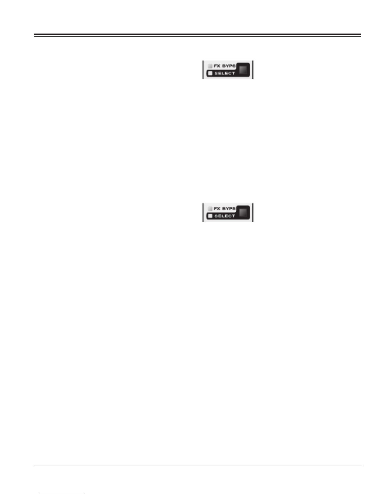
Plug-In Bypass
When the green “bypass” LED is lit,
the MULTI switches will bypass all
the inserts on the selected channel.
Press the MULTI switch to toggle the bypass status of a
channel’s inserts. A solid lit green MULTI LED indicates
that inserts 1-5 on that channel are bypassed. A blinking
green MULTI LED indicates that one or more inserts (but
not all) on that channel are bypassed.
Whenever MotorMate is editing a plug-in, that plug-in
can be bypassed, or made active, by pressing the SHIFT
switch down, then the BYPASS switch (3rd one up, left of
the faders). All the session plug-ins can be bypassed or
made active while the MULTI switches are in FX BYPS
mode. Simply press and hold down the ALL switch and
press any channel MULTI switch.
Plug In Channel Select
Press the second Multi Mode switch
to light the SELECT LED. The
channel MULTI switches are now
used to select other channels for plug-in editing. If
MotorMate was editing parameters (rotary display
showing “PA”), it will return to insert mode and will select
another channel for plug-in editing. The channel selected
will have its track label displayed on the top row of the
LCD.
If a MULTI switch is pressed quickly, twice in sucession,
the next insert in the selected channel will be brought
forward for editing.
Assigning Plug-In’s
Press and hold SHIFT (on the MotorMate lower panel)
and then press “assign” on the MotorMate lower panel.
The ASSIGN LED will flash to show that assignment is in
process. During assignment, the Burn Mode Switches
and the Rotary Mode Switches are all disabled.
The Rotary Display will show “IN” for insert, and any
SELECT LED’s that were on, now go off. Rotate the
rotary pots to move through the list of assignment
choices. The choices will appear on the LCD bottom row
as you do this. Press the View Stick up to access insert 5
for assignment.
Push the View Stick up, and the LCD will briefly show
“Page 2/2 slap delay (Ins 4)”. This means that page 2
of 2 parameter pages is displayed, the plug-in is a slap
delay and it is on insert 4 in the channel strip. Here, all
the parameters on page 2 can be viewed or changed.
Pushing the View Stick up goes up through the pages,
and pushing it down goes down through the pages.
Page 16 CM Labs MotorMate Owner’s Manual
When the SELECT LED flashes, it indicates that the
choice in that channel input or output assignment is not
the original one. When the desired assignment is shown
on the LCD, press that channel’s SELECT switch. That
will lock in that assignment on that channel. The channel
SELECT will light solid to indicate it is locked in.
Page 17

Mixer Controls
Other MULTI Switch Functions
PUNCH
Press the third Multi Mode switch,
and the PUNCH LED will light. The
MULTI switches then will activate
the functions labelled below them.
The left most 5 switches are the audition switches. These
are labelled AUD (audition), PRE (pre roll), IN (edit
selection start), OUT (edit selection end), and POST
(post roll).
AUD
Press the AUD switch and the LED will light and the
audition features of the software become active. Audition
followed by combinations of PRE, IN, OUT, or POST
allows the user to audition in and around an edit point.
Audio playback in progress will continue until AUD is
pressed again to disable it.
PRE
Press the PRE switch to play from the pre-roll point to
the start of the edit selection. This mimics the option left arrow on the keyboard.
IN
Press the IN switch to play from the start of the edit
selection and play the length of the pre-roll. This mimics
the command - left arrow on the keyboard.
If you press the IN switch while playing, it enters the
selection IN point on the fly.
OUT
Press the “out” switch to play from the end of the edit
selection and play the length of the post-roll. This mimics
the option - right arrow on the keyboard.
Press and hold ALT and OPT on the keyboard together
and then press PRE or IN and play will go from the preroll point through the edit selection and end after the
post-roll time. This mimics the command - option - left
arrow on the keyboard.
Press and hold the keyboard ALT and OPT on the
keyboard together and then press OUT or POST and
play will go from before the edit selection end by the preroll amount through the edit selection and end after the
post-roll time. This mimics the command - option - right
arrow on the keyboard.
When audition is active, you can press any of the other
audition switches and instantly go from auditioning one
selection to another.
PNCH, LOOP, and SUSP
To the right of the 5 audition switches are the PNCH,
LOOP and SUSP switches.
PNCH
Press the PNCH switch to enable auto punch.
LOOP
Pressing the LOOP switch will cause the edit selection to
play from start to end (in to out) and then repeat
continuously. To activate loop record, press and hold
CTRL on the keyboard and then press LOOP.
SUSP
Press the SUSP switch, and automation playback will be
suspended. When automation is suspended, the SUSP
LED will blink on and off.
If you press the OUT switch while playing, it enters the
selection OUT point on the fly.
POST
Press the POST switch to play from the end of the edit
selection and play the length of the pre-roll. This mimics
the command - right arrow on the keyboard.
CM Labs MotorMate Owner’s Manual Page 17
Page 18

Mixer Controls
The Burn Section
BURN Mode Switches
BURN Mode LED’s (6)
The MotorMate BURN section includes the row of 8
switches/red LED’s above the Mute and Solo switches
and the 3 Burn Mode switches and 6 Burn Mode LED’s to
their left.
Record Operations
The Top Burn Mode Switch determines whether you are
going to use the 8 BURN switches for channel record
readies (labelled “record”) or automation controls
(labelled ”write”).
When the red “record” LED is lit, the 8 BURN switches
operate the channel record enables. They arm the track
for recording. Press a channel BURN switch and its LED
flashes to indicate it is enabled for recording. When
actually recording, the LED will light solid.
Press and hold the keyboard OPT switch and press any
channel BURN switch, and all channel record enables
will change to match the new state of the channel that
was pressed. If a selection of channels has been made,
press and hold the OPT switch and SHIFT switch and
press any channel BURN switch, and all selected
channels will be armed for recording.
Software Record Safe Mode
Channel strips can be placed into Record safe mode by
holding down the SHIFT switch and ALT/FINE switches
and pressing a channel Record Enable switch. The
switch LED will briefly blink to indicate that the user has
changed its status. There is no other indication on
MotorMate that a channel has been “safe’d” in this
manner. ProTools will show the record buttons as grayed
out on screen in the Mix Window.
In Record safe, pressing a Record Enable switch will
have no effect. Press and hold Command on the
keyboard and then ALL and a Record Enable switch to
clear or set safe status on all channels. Press and hold
ALL then Command on the keyboard and then SHIFT
and a Record Enable switch to clear or set safe status on
all selected channels.
MotorMate can also be put in Record Safe mode by
entering UTILITY mode. See page 26 for details.
Channel BURN Switches (8)
Selecting Automation Modes. Method 1
Press the switch next to the “record” LED, and the yellow
“write” LED will illuminate. This indicates that the 8
BURN switches operate the channel automation modes.
Press and hold a channel BURN switch, and the current
channel automation mode will be displayed on the
bottom row of the LCD. With the switch held down, rotate
the rotary pot in that channel, and the mode will be
changed. As you continue to rotate the pot, all the
various modes will be seen on the LCD.
When the desired mode is selected, release the BURN
switch. The channel BURN switch LED will remain off for
Off and Read modes, and it will blink if a Touch mode is
selected. Otherwise, the LED stays lit solid.
Changing Automation Modes for All Channels
Press and hold a channel BURN switch. The current
channel automation mode will be displayed on the
bottom row of the LCD. Then hold down the ALL switch.
With both switches held down, rotate the rotary pot in
that channel, and the mode will be changed on all
session channels.
Selecting Automation Modes. Method 2
Press SHIFT and MODE on the lower panel of
MotorMate, and it will display the automation modes for
the current bank of 8 channels. You can rotate any of the
rotaries to change their automation modes.
Changing Automation Modes for All Channels
Hold down the ALL switch, then rotate the rotary pot in
that channel, and the mode will be changed on all
session channels.
Press the ENABLE switch or SHIFT “mode” to exit.
Page 18 CM Labs MotorMate Owner’s Manual
Page 19

Mixer Controls
Using the Automation Modes
First, put the BURN switches in “write” mode as
described earlier. Then, enable the parameter type for
automation and make sure “Suspend” is off.
Off Mode
If a channel is in “off” mode, then no automation will play
on that channel, and no updates will be made to the
automation on that channel.
Read Mode
If a channel is in “read” mode, then automation will play
on that channel, but no updates will be made to the
automation on that channel.
Touch Mode
If a channel is in “touch” mode, rotate the channel rotary
pot, and the parameter change will be punched in. If you
stop moving the pot, it will drop back after the touch
time-out has elapsed (set as an automation preference in
software).
Latch Mode
If a channel is in “latch” mode, you can either rotate the
channel rotary or press the channel BURN switch to
punch in an automation move.
Write mode
If a channel is in “write” mode, any parameter change
made during play will be updated until play is stopped.
Automation Enables
Press and hold the ENABLE, and the LCD will display
“FADR MUTE PAN SEND SENDM PLUG-IN SUSP”.
The SELECT LED’s will show the current state for these
enables, and the SELECT switches toggle them on and
off.
Enable Fader Automation
If the FADR LED is on, then fader level changes will be
updated in the automation.
Enable Mute Automation
If the MUTE LED is on, then mute changes will be
updated in the automation.
Enable Pan Automation
If the PAN LED is on, then pan setting changes will be
updated in the automation.
Enable Send Level Automation
If the SEND LED is on, then send level changes will be
updated in the automation.
Enable Send Mute Automation
If the SENDM is on, then send mute changes will be
updated in the automation.
Enable Plug In Automation
If the PLUG-IN is on, then plug-in parameter changes will
be updated in the automation if the particular plug-in
parameter has been automation enabled in the plug-in
window.
Automation Suspend
If the SUSP led is blinking, then automation playback
and updating has been disabled globally. This switch
duplicates the function of the “susp” switch in the
PUNCH mode for the MULTI row of switches on
MotorMate. All channel mixer settings are left in their
current state and the channel automation mode is
unchanged, but “dormant”.
CM Labs MotorMate Owner’s Manual Page 19
Page 20
Mixer Controls
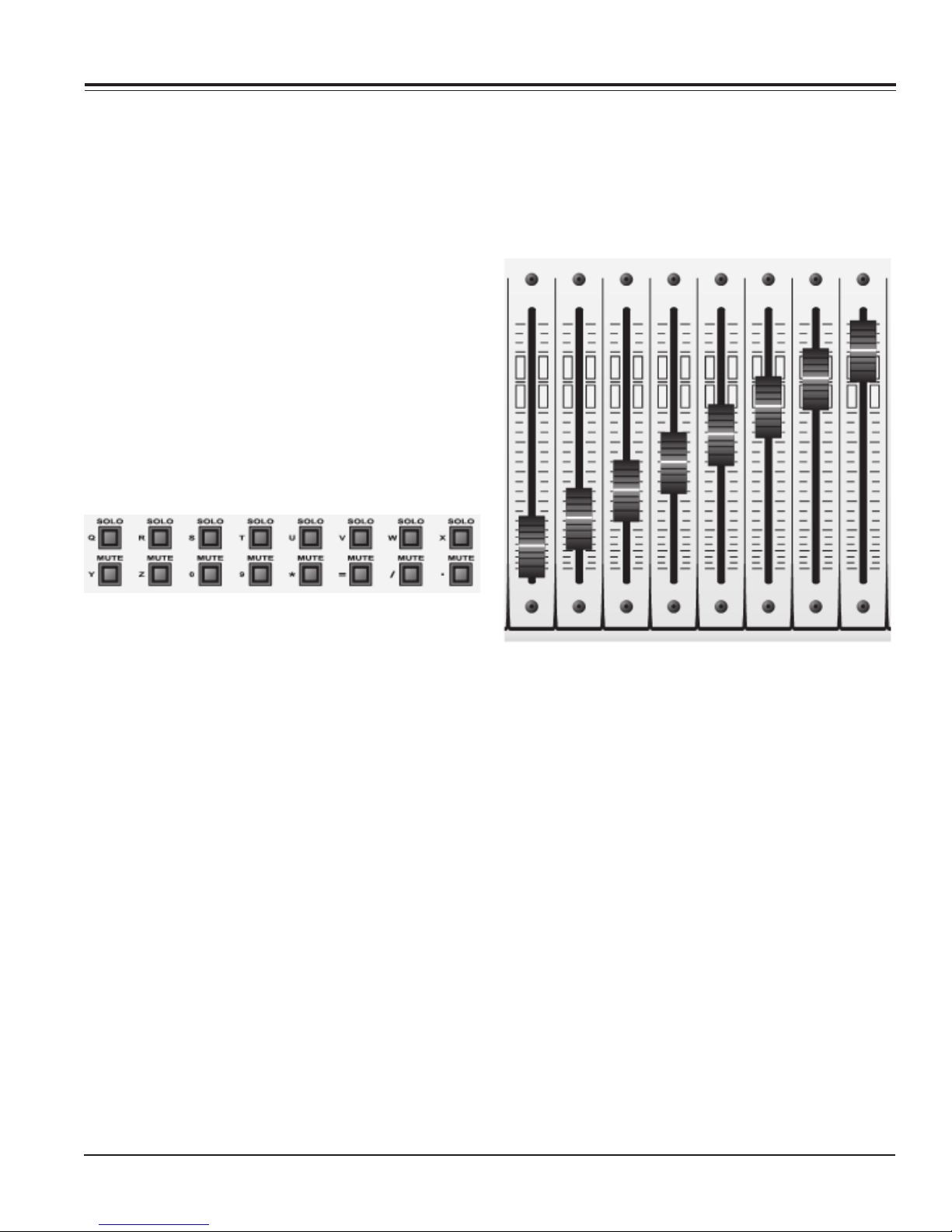
MUTE and SOLO
These switches activate the DAW console mute and solo
functions. The LED’s in these switches reflect the mute
and solo state of the DAW console. Additionally, press
and hold the OPT switch and either a MUTE or SOLO
switch to clear or set all mutes or solos on the console.
Press and hold the OPT switch and SHIFT switch and
either a MUTE or SOLO switch to clear or set all
selected channels mutes or solos on the console.
In ProTools, there are several preferences you can set
for solo and mute operation. These are Solo Latch, Solo
Safe, Solo follows Mix Groups, and Mute follows Mix
Groups. MotorMate will act and be updated in a manner
consistent with screen mute and solo functions for each
of these preferences. When a Mute or Solo is on, the
LED lights solid. Solo’ed channels will flash the LED’s on
Mute switches that are not actually muted. The Mute
LED’s on channels that are actually muted will be lit
solid.
Setting Aux Levels with the Faders (Fader Flip)
With the rotaries in send mode, press in the View Stick,
and the aux levels will be flipped down to the faders so
you can make your send level changes on them. The
upper row of the LCD will display the send buss
assignments.
Solo Safe Mode
Channel strips can be placed into Solo safe mode by
holding the ALT switch and pressing a channel Solo
switch. The switch LED will briefly blink to indicate that
the user has changed its status. There is no other
indication on MotorMate that a channel has been “safe’d”
in this manner. ProTools will show the solo button as
grayed out on screen in the Mix Window.
In Solo safe, pressing a Solo switch will have no effect.
Press and hold Command on the keyboard and then ALL
and a Solo switch to clear or set safe status on all
channels. Press and hold ALL then Command on the
keyboard and then SHIFT and a Solo switch to clear or
set safe status on all selected channels.
Faders
Setting Mix Levels
The faders are used for setting mix levels. They are
motorized, so when automation is playing back, they will
move to reflect the actual mix levels. When you touch
the fader knob, the motor is disengaged to allow you to
make changes without fighting the motor.
Press in the View Stick again to return the faders to
controlling the mix levels.
Viewing the Fader Levels in dB
Press and hold SHIFT and ALT/FINE together and touch
a fader knob, and then the mix level will appear on the
lower row of the LCD in dB’s as you move the fader, the
values will appear on the LCD.
Defaulting a Fader to Unity
Press and hold the DEFAULT switch and then press a
channel SELECT switch, and the fader will move to unity.
Defaulting all Faders to Unity
Press and hold the ALL switch first, then press and hold
the DEFAULT switch. Pressing any channel SELECT
switch will move all the faders in the session to unity.
Page 20 CM Labs MotorMate Owner’s Manual
Page 21
Transport Controls
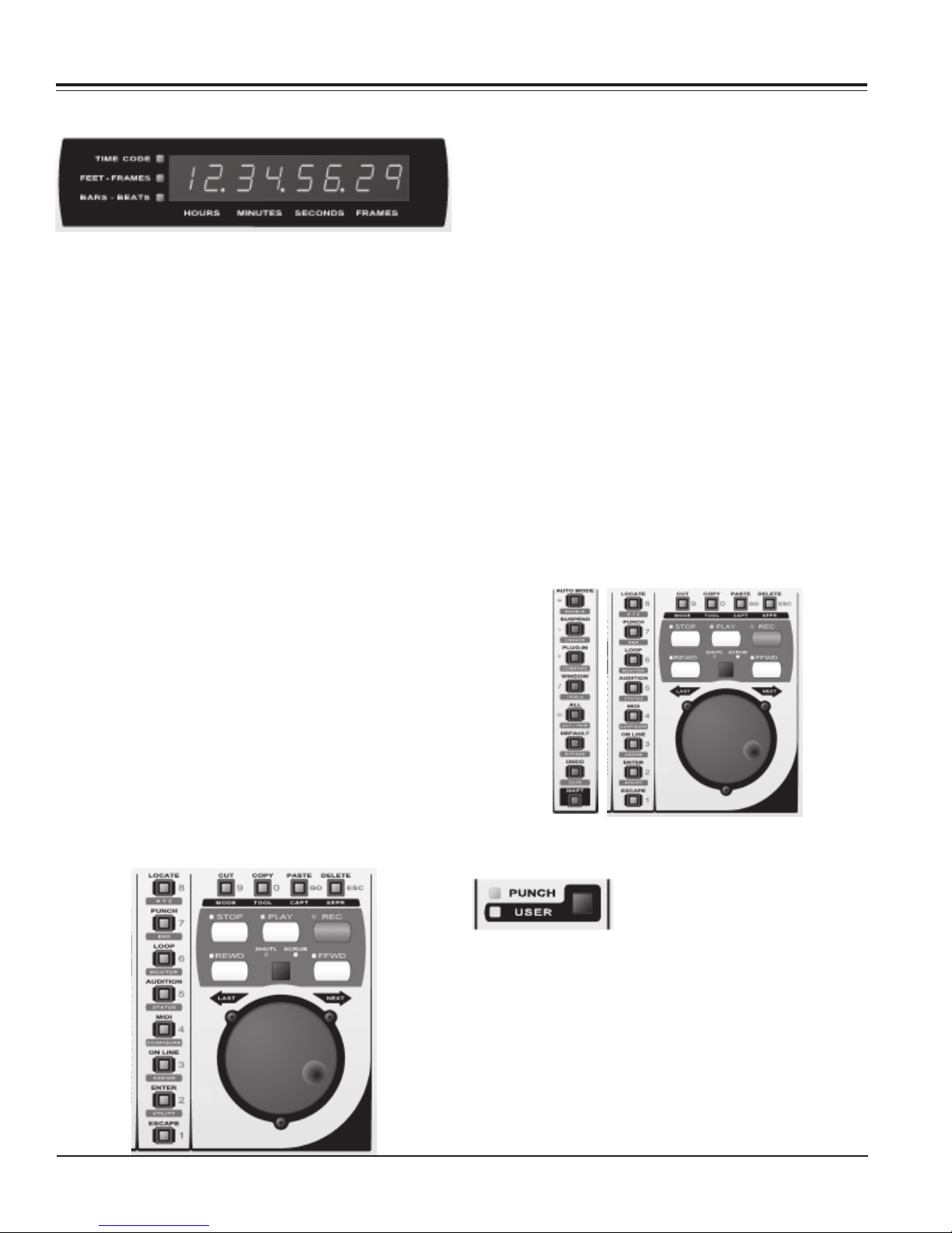
Time Code Display
The Time Code display has eight 7-segment LED numeric displays and 3 mode LED’s to the left of the
display. These mode LED’s indicate the current time
display format.
“t.c.” LED on = Timecode display format:
HOURS:MINUTES:SECONDS:FRAMES
“feet” LED on = Timecode display format:
FEET:FRAMES
“beats” LED on = Timecode display format:
BARS:BEATS
no LED on = Timecode display format:
MINUTES:SECONDS
or
SAMPLES
Adding Locate Points to Memory
Locate points can be entered to memory by pressing
ENTER as the transport is running (it uses the next free
location). Press ENTER a second time to add the point to
the list, or press ESC to cancel without entering it.
Next and Last Locate
Press and hold the SHIFT switch, and the FFWD and
REWD switches move the transport to the next or last
locate point in the locate window.
Locate Mode
Press the LOCATE switch, the software locate list will
open on screen, and the LOCATE and ESC LED’s will
begin to flash indicating that locate mode is active. When
locate mode is on, the labels in grey beside the lower
panel switches indicate their use. Pressing one or two
number switches followed by GO recalls a memory
position. Press ESC (in grey next to the DELETE switch)
to exit locate mode, and the on screen locate list will
disappear. If you want to exit locate, but leave the locate
list on-screen, hold down SHIFT as you pres ESC.
The display uses periods as delimiters. The timecode
display mode is set in ProTools from the big counter
window. Some time displays, such as
MINUTES:SECONDS have a least significant digit
display in thousandths of a second (three characters).
These values will be displayed with 2 digit accuracy.
The right most period blinks on and off when MotorMate
is on-line.
Transport Switches
These switches activate the DAW basic transport functions. The Rewind and Fast Forward switches can be
either Momentary or Latching types. See Page 26 under
UTILITY mode for details
Enter Pre Roll, In, Out, or Post Roll. Method 1
The MULTI switches must first be
in PUNCH mode by pressing the
Multi Mode switch labelled PUNCH
switch so the PUNCH LED is on.
Press and hold SHIFT and ALL together then press either
PRE, IN, OUT, or POST or POST. The PRE, IN, OUT, or
POST LED will blink then to indicate that you are editing
that value.
The current time will be displayed on the MotorMate
timecode display, and the current edit field will blink on
and off.
CMLabs MotorMate Owner’s Manual Page 21
Page 22
Transport Controls
Use the Navigation controls to
edit the values. Both the Zoom
Stick horizontal and Left and
Right navigation switches
control which field is being
edited. As you move the Zoom Stick left or right or press
the Left or Right navigation switches, the edit field will
change, and the timecode display will blink on and off the
current field to be edited.
Both the Zoom Stick vertical and Up and Down navigation switches edit the currently selected field. As you
move the Zoom Stick up or down or press the Up or
Down navigation switches, the value will change, and the
timecode display will show the value as it changes.
You can revert to the old values and exit by pressing the
ESC switch on MotorMate. You can save the new values
and exit by pressing the ENTER switch on MotorMate.
Enter Pre Roll, In, Out, or Post Roll. Method 2
The MULTI switches must first be
in PUNCH mode by pressing the
Multi Mode switch labelled PUNCH
so the PUNCH LED is on.
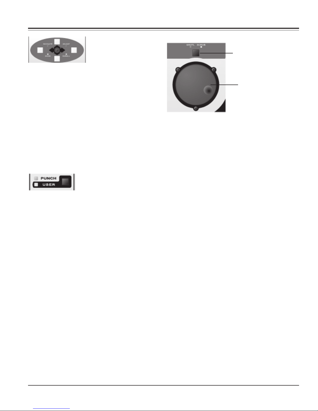
Scrub and Shuttle Controls
Jog Mode Switch
Jog Wheel
When scrub or shuttle are engaged, only certain of the
controls on MotorMate will remain active:
1.) Jog wheel and Jog select switch.
2.) Transport switches (which cause shuttle or scrub to
disengage).
3.) Channel faders, Mutes, or Solos.
Scrub
Press the Jog Mode switch just above the jog wheel. The
SCRUB LED will light to show that it is in scrub mode.
When scrub is engaged, rotating the jog wheel will scrub
play whatever tracks are selected by the edit cursor.
Press and hold SHIFT and ALL together then press either
PRE, IN, OUT, or POST or POST. The PRE, IN, OUT, or
POST LED will blink then to indicate that you are editing
that value.
The current time will be displayed on the MotorMate
timecode display, and the current edit field will blink on
and off. MotorMate will also open the transport window if
it is not already open.
Press the LOCATE switch and you can enter the values
on the numeric switches. Use the GO switch to tab to a
field for editing. As you press the GO switch, the edit field
will change, and the timecode display will blink on and off
the current field to be edited.
You can revert to the old values and exit by holding down
SHIFT and pressing the ESC switch on MotorMate. You
can save the new values and exit by holding down
SHIFT and pressing the ENTER switch on MotorMate.
MotorMate will also close the transport window if it is was
already open.
Entering Values into the Big Counter
Press LOCATE on MotorMate. Then press the “=” switch
(the ALL switch) and you can enter values into the big
counter by the same two methods just described.
Page 22 CM Labs MotorMate Owner’s Manual
Scrubbing with the SHIFT switch down will make a region
selection.
Fine Scrubbing
Rotate the jog wheel in scrub mode with the ALL switch
held down, and fine scrubbing will occur.
Scrubbing with the SHIFT and ALL switch down will make
a region selection while fine scrubbing.
Shuttle
Press and hold SHIFT, and then press the Jog Mode
switch to enter shuttle. The SHUTTLE LED will light to
show that it is in shuttle mode.
In shuttle mode, rotating the wheel clockwise from center
shuttles forward at high speed and the F FWD and PLAY
LED’s will light. In like manner, rotating the wheel counter
clockwise from center shuttles the transport backward at
high speed and the REW and PLAY LED’s will light.
The speed of shuttling is determined by how far the wheel
is rotated from its center point. Press any transport
switch to exit shuttle mode.
Additionally, shuttling with the SHIFT switch down will
make a region selection.
Page 23
Edit and System Controls
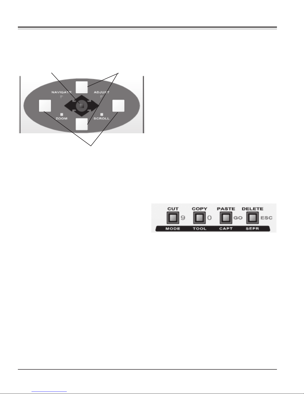
Zoom and Navigator Section
This section has 2 Track Navigator switches and 2 Time
Navigator Switches, and the Zoom Stick at the center.
The 4 mode LED’s are labelled “navigate”, “zoom”,
“scroll” and “adjust”.
Zoom Stick Track Navigator Switches
Time Navigator Switches
Zoom Stick
Moving the Zoom Stick horizontally controls the expansion or contraction of the horizontal (or time) axis in the
edit window. Moving the Zoom Stick to the left contracts
the time line, and moving it to the right expands the time
line.
Moving the Zoom Stick vertically controls the expansion
or contraction of the vertical (or amplitude) axis in the edit
window. Moving the Zoom Stick up expands the waveform, and moving it down contracts the waveform.
Press and hold the ALL switch, and then either of the
Time Navigator switches will center the currently selected region in the edit window.
Adjust Mode
Press in on the Zoom Stick to toggle to Adjust mode. The
ADJUST LED will light.
Adjust Start of Edit Region
Press and hold the left Time Navigator switch and rotate
the Jog wheel.
Adjust End of Edit Region
Press and hold the right Time Navigator switch and
rotate the Jog wheel.
Adjust Region Position Retaining its Length
Press and hold both the left and right Time Navigator
switches and rotate the Jog wheel.
Changing or Adding Tracks to Selection
Pressing the Track Navigator switches moves the edit
cursor up and down tracks in the edit window.
Press and hold SHIFT first, and then these switches will
add or subtract tracks to the cursor.
Clipboard Switches
When the Zoom Stick is moved horizontally or vertically,
the ZOOM LED lights to show that zooming is taking
place. If none of the ZOOM LED’s are on, then press any
control in the Zoom and Navigator section, and the
Software will update them properly.
Pressing in on the Zoom Stick toggles between the 2
Navigate modes which are Navigate and Adjust.
Track and Time Navigator Switches
Navigate Mode
When the NAVIGATE LED is lit, the Navigate switches
are in Navigate mode. Pressing the Track Navigator
switches moves the edit cursor up and down tracks in the
edit window. Press and hold SHIFT first, and then these
switches will add or subtract tracks to the cursor.
Pressing the Time Navigator switches moves the edit
cursor to the previous or next region boundary or sync
point. Press and hold SHIFT first, and then these
switches will select regions forward or backward.
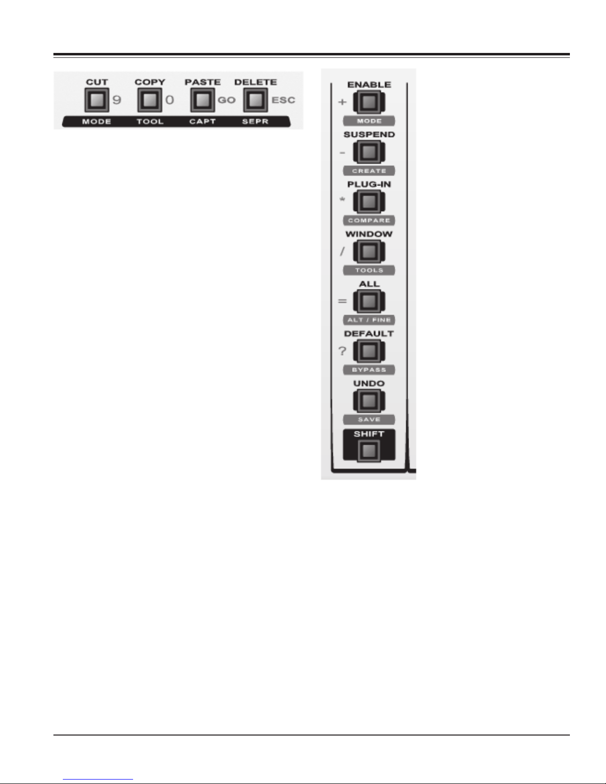
CUT, COPY, PASTE, DELETE
These 4 switches each have secondary functions as well.
When the SHIFT switch is held down these become
MODE, TOOL, CAPT, and SEPR controls.
CUT
Pressing the CUT switch removes the currently selected
edit region and places it in the clipboard.
COPY
Pressing the COPY switch makes a copy of the currently
selected edit region and places it in the clipboard.
PASTE
Pressing the PASTE switch takes the clipboard contents
and copies it to the selected tracks beginning at the edit
cursor location.
DELETE
Pressing the DELETE switch removes the currently
selected edit region, but does not place it in the clipboard.
CM Labs MotorMate Owner’s Manual Page 23
Page 24
Edit and System Controls
MODE
Press and hold SHIFT, then press the MODE switch to
cycle through the 4 edit modes: Shuffle, Slip, Spot, and
Grid. These modes are described in detail in the ProTools owners manual.
TOOL
Press and hold SHIFT, then press the TOOL switch to
cycle through the 6 edit tools: Zoom, Scrub, Trim, Select,
Grab, Pencil. These tools are described in detail in the
ProTools owners manual.
CAPTURE
Press and hold SHIFT, then press the CAPTURE switch.
This will define a selection as a new region and add it to
the Regions List.
SEPARATE
Press and hold SHIFT, then press the SEPERATE
switch. This will define a selection within an existing
region and separates it from adjacent material.
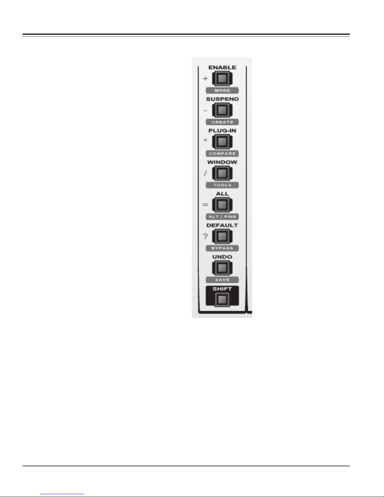
SHIFT
Generally speaking, SHIFT is
used to add things to a selection
of controls, channels, or tracks.
For example, press and hold
SHIFT down and then press
several channel SELECT
switches. All the SELECT
switches that were pressed will
then have their LED’s lit to show
that they are all selected. You
could think of the SHIFT switch
as the SHIFT/add switch.
Additionally, holding down the
SHIFT switch will cause the
bottom row of the LCD to display
audio meters for the 8 currently
viewed channels.
The SHIFT switch must be held
down to access any of the
functions labeled below the
switches.
UNDO
When this LED is lit, it means
that the current session has been
changed in some way and that
the undo option is available.
Press the UNDO switch to undo
the last edit operation. If the
UNDO LED remains lit, it means
that more “undo’s” are needed to
return to the original state. Press
the UNDO switch to continue
undoing. If the UNDO LED goes off, then the session is
unaltered. When this LED is blinking, it means that the
redo option is available. Press the UNDO switch to redo
the last edit operation.
Page 24 CM Labs MotorMate Owner’s Manual
SAVE
When this LED is lit, it means that the current session
has been changed in some way. Press the SAVE switch,
and the SAVE LED will flash as if to ask “are you sure?”
Press the SAVE switch a second time to save the session file. The SAVE LED will turn off. While the SAVE
LED is flashing, you can press the ESC switch to abort
the save, and the SAVE LED will light solid again.
DEFAULT
When the lower panel “default” switch is active, the
SELECT switches are used to set faders, pans and sends
to their default values.
Page 25
Edit and System Controls
BYPASS
While in Plug-in mode and displaying inserts, press and
hold SHIFT and BYPASS. Then press one of the channel
SELECT switches to bypass that plug-in.
ALL
The ALL switch is used to make changes to all channels.
For example, press and hold the ALL switch and press a
channel SELECT switch and all the channels will be
selected.
ALT/FINE
This switch is used for many things including:
PAN
Pressing SHIFT and ALT/FINE down while rotating a pan
pot will display its value numerically from -100 to +100 on
the top row of the LCD.
SEND
Pressing SHIFT and ALT/FINE down while rotating a
send pot will display its value numerically from off to
+6dB on the top row of the LCD.
FADERS
Pressing SHIFT and ALT/FINE down while touching or
moving a fader will display its value numerically from off
to +6dB on the top row of the LCD.
SCRUB
Pressing SHIFT and ALT/FINE down while scrubbing will
cause fine scrubbing.
WINDOW
Press and hold the WINDOW switch and its LED lights
up and the LCD display shows the various window
names, and the LED’s on the SELECT switches show the
status of the windows. Press the SELECT switch under
“MIX” to bring the Mix window to the foreground. Press
the SELECT switch under “EDIT” to bring the Edit
window to the foreground.
TOOLS
Pressing SHIFT and TOOLS will cycle through the edit
tools.
PLUG-IN
If both the “bypass” and “select” LED’s are off, press the
PLUG-IN switch. The Rotary Display will display either
“IN” for insert, or “PA” for parameter. Simultaneously,
MotorMate will open the currently selected plug-in. If
none is selected, See Page 16 for Plug-in operation.
SUSPEND
Press the “SUSPEND” switch to
globally suspend playback and
recording of automation. The
LED will blink. Press again to
globally reactivate playback and
recording of automation.
CREATE
The CREATE switch is used to
create groups. First use the
SELECT switches below the
LCD to select a channel to
include in a group. Press and
hold the SHIFT switch . Press
more select switches to add
channels. With SHIFT still down
press the CREATE switch and
the Pro Tools Group dialog box
will appear. Press the ENTER
switch on MotorMix to complete
the process or ESC to exit
without grouping.
The GROUP switch and LED
under the VIEW section on
MotorMix are used to enable/
disable groups. If the LED is lit,
the groups are enabled. With
groups enabled, press and hold
the SHIFT switch then hold the
GROUP switch down. The top
row of the LCD will show the
channel group assignments.
ENABLE
Press and hold the ENABLE, and
the LCD will display “FADR MUTE PAN SEND
SENDM PLUG IN SUSP”. The SELECT LED’s will
show the current state for these enables, and the
SELECT switches toggle them on and off.
MODE
Press SHIFT and MODE on the lower panel of
MotorMate, and it will display the automation modes for
the current bank of 8 channels. You can rotate any of the
rotaries to change their automation modes.
Reset MotorMate
To reset MotorMate, press SHIFT, UNDO, and ENABLE
at the same time.
COMPARE
This switch will allow the comparison of the present plugin parameter settings to the previous settings.
CM Labs MotorMate Owner’s Manual Page 25
Page 26 CM Labs MotorMate Owner’s Manual
Page 26
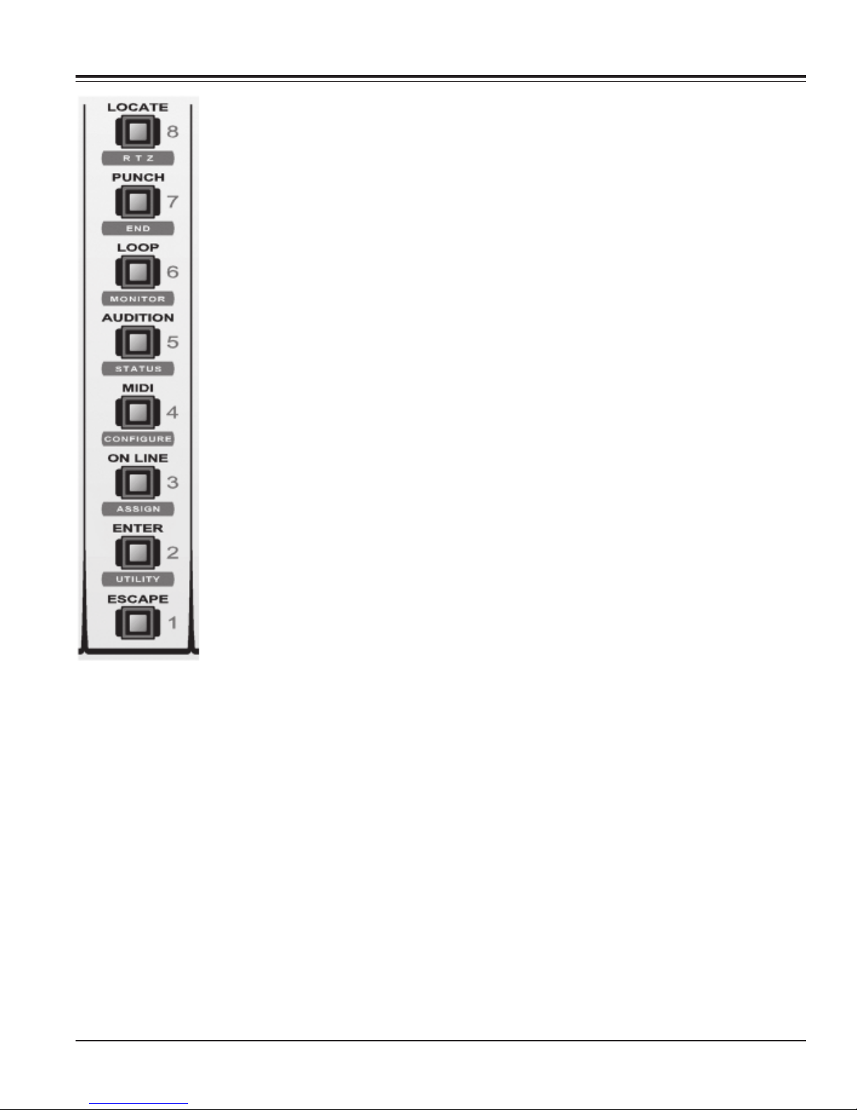
Edit and System Controls
ESC
The ESC (escape) switch is used to
exit processes without keeping the
result. It is context sensitive.
ENTER
The ENTER switch is used to
complete processes and to enter
locate points on the fly.
UTILITY
Press and hold SHIFT and then
press UTILITY. Release the SHIFT
switch.
The LCD will display the Record
Safe state, Latching or Momentary
states for the Rewind (REWD) and
Fast Forward (FFWD) switches,
and the Motors ON/OFF status.
Record Safe
When the Record Safe is ON, the
Master Record Switch and the
channel BURN switches (when in
rec/rdy mode) will be locked out.
Press SELECT 1 or SELECT 2 to
change the state. The new state
will NOT be stored in nonvolatile
memory, so Record Safe will be
OFF at power up.
REWD and FFWD options
When these switches are in
Momentary mode, the FFWD or REWD switches must
be held down to keep the transport rewinding or fast
forwarding. When these switches are in Latching mode,
the FFWD or REWD switches must be pressed once to
start the transport rewinding or fast forwarding, and
pressed again to stop.
Press SELECT 4 or SELECT 5 to change the state. The
new state will be stored in nonvolatile memory, so it will
be remembered at power up.
Motors ON/OFF
When the Motors are ON, the faders will move
whenever the Software tells them to move. When the
Motors are OFF, the faders will not move.
Press SELECT 7 or SELECT 8 to change the state. The
new state will NOT be stored in nonvolatile memory, so
the motors will be ON at power up.
ON LINE
The ON LINE switch controls punch-in/out behavior.
If you are not on line, recording begins and stops
whenever you press the Record switch, regardless of the
selections start or end point. If you are on line, punch-in/
out occurs only within the selection.
ASSIGN
The ASSIGN switch is used for making channel input/
output assignments, send buss assignments, and plug in
assignments.
MIDI
As of this writing, this is unimplemented and is reserved
for future use.
CONFIGURE
As of this writing, this is unimplemented and is reserved
for future use.
AUDITION
Press the AUDITION switch and the LED will light and
the audition features of the software become active.
Audition followed by combinations of PRE, IN, OUT, or
POST allows the user to audition in and around an edit
point. Audio playback in progress will continue until AUD
is pressed again to disable it. This switch is a duplicate of
the MULTI switch 1 when in PUNCH mode.
STATUS
Press STATUS, and the system status window will open
or close.
LOOP
Pressing the LOOP switch will cause the edit selection to
play from start to end (in to out) and then repeat
continuously. To activate loop record, press and hold
CTRL on the keyboard and then press LOOP. This switch
is a duplicate of MULTI switch 7 when in PUNCH mode.
MONITOR
Hold down SHIFT and press MONITOR to clear the peak
and last held channel meters.
PUNCH
Press the PUNCH switch to enable auto punch. This
switch is a duplicate of MULTI switch 6 when in PUNCH
mode.
END
Press END and the play pointer will move to the end of
the session time line.
Page 26 CM Labs MotorMate Owner’s Manual
Page 27
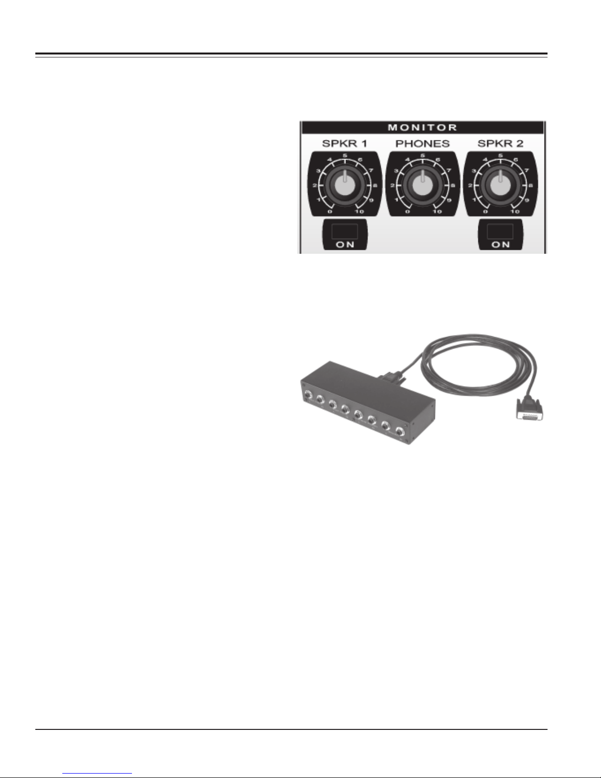
Monitor Controls
LOCATE
Press the LOCATE switch, and the LOCATE and ESC
LED’s will begin to flash indicating that locate mode is
active. When locate mode is on, the labels in grey beside
the lower panel switches indicate their use.
Pressing one or two number switches followed by GO
recalls a memory position. Press ESC (in grey next to the
DELETE switch) to exit locate mode.
RTZ (Return to Zero)
Press RTZ and the play pointer will move to the start of
the session time line.
Monitor Section
The monitor section has 3 rotary pots and 2 switches to
control 2 sets of speakers and a front panel headphone
jack.
Typically, you would have the Speaker 1 outputs on the
MIM connected to your main control room speakers and
the Speaker 2 outputs on the MIM connected to your
auxiliary control room speakers or to speakers in the
studio or overdub room.
Monitor Interface Module (MIM)
The Speaker 1 pot controls the volume of the speakers
fed from the Speaker 1 outputs on the MIM, and the
switch just below the pot turns the speaker on and off.
This switch is convenient to turn off the main control
room speakers and use the headphones if you track from
the control room .
The Speaker 2 pot controls the volume of the speakers
fed from the Speaker 3 outputs on the MIM, and the
switch just below the pot turns the speaker on and off.
This switch is convenient to turn off the auxiliary control
room speakers or studio speakers during tracking overdubs.
The Phones pot controls the volume of the headphone
jack on the front edge of MotorMate.
CM Labs MotorMate Owner’s Manual Page 27
Page 28
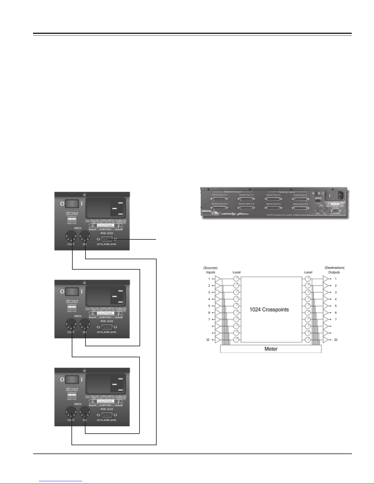
Appendix A: Controlling the SixtyFour from MotorMate
Installation and Connections
RS-232 Connections
Use a CM Labs CAB912 cable or a standard 9 pin male
to female cable. The cable has a 1 to 1 pinout. Connect
the cable from the MotorMate rear panel RS-232 connector to the RS-232 connector on the CM Labs SixtyFour
Studio Router. If you are using only 1 SixtyFour Router,
move on to the Audio Connections section.
If using more than 1 SixtyFour Router, connect the MIDI
output of Router 1 to the MIDI input of Router 2 and so on
in a “daisy chain” as shown in the diagram below. Connect the MIDI output of the last Router in the chain to the
MIDI input of Router 1.
MotorMate will control all 3 Routers over the single RS232 connection.
SixtyFour router (Router 1)
After you have connected one or more SixtyFours to
MotorMate, you must check to see that each one is set to
SLAVE mode.
Step 1.) With the SixtyFour unlocked (Save and Route
LED’s not blinking) push in the Level and Meter switches
on the SixtyFour to enter Utility mode.
Step2.) Push in the SixtyFour Encoder twice, and the
master/slave status appears. It shows as either NST
(master) or SLV (slave) in numeric display. Simply turn
the rotary control knob until it shows SLV (slave).
Step 3.) Push in the Level and Meter switches on the
SixtyFour to exit Utility mode.
Repeat steps 1 through 3 for any additional SixtyFours
present.
SixtyFour router (Router 2)
SixtyFour router (Router 3)
to MotorMate.
Audio Connections
The SixtyFour rear panel has 4 DB25 connectors for the
32 Source inputs and 4 DB25 connectors for the 32
Destination outputs. Mono, Stereo, Surround or other
multi channel devices can be interfaced.
SixtyFour Audio Block Diagram
Connect the audio outputs of external devices to the
Source Inputs on the SixtyFour. Connect the SixtyFour’s
Destination Outputs to the inputs of external devices. You
may connect your audio devices to the SixtyFour by
several methods.
Page 28 CM Labs MotorMate Owner’s Manual
Devices equipped with DB25 connectors:
Use standard DB25 to DB25 audio snakes. Connect the
snake to the SixtyFour rear panel and tighten the screws
included with the snakes. Connect the other end to the
DB25 equipped device and tighten the screws.
Page 29
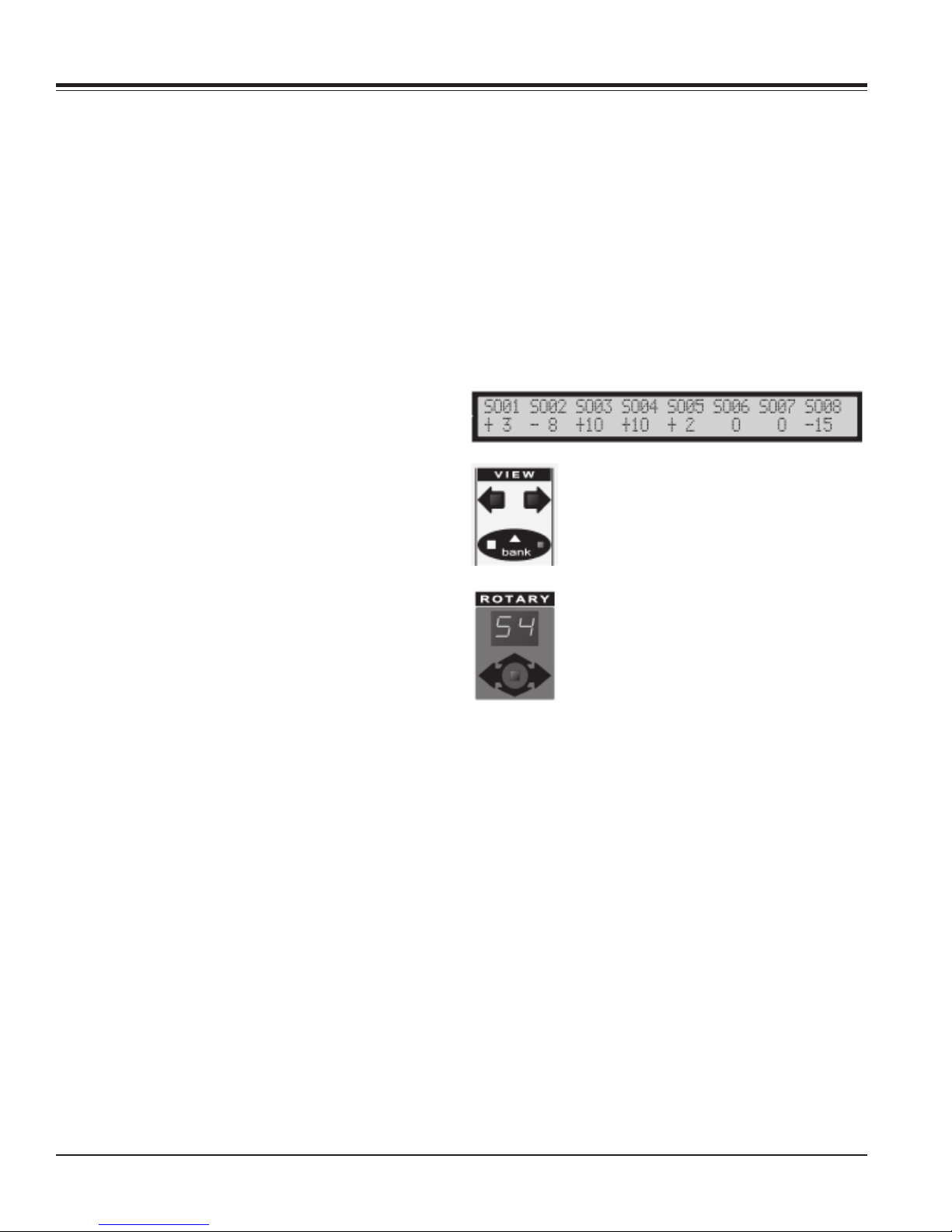
Appendix A: Controlling the SixtyFour from MotorMate
There are two ways to connect devices equipped with
XLR or 1/4” phone jacks:
1.) The CM Labs DB-8 terminal strip adaptor. Wire up the
DB-8 up according to the pin connections given on it.
2.) Use standard DB25 to 1/4” or XLR audio snakes.
Connect the DB25 end of the snake to the SixtyFour rear
panel and tighten the screws included with the snakes.
Connect the individual connector end of the snake to the
1/4” or XLR connectors on the external device.
Mono Connections
Mono Sources or Destinations may be connected to any
of the 32 inputs or 32 outputs on the SixtyFour.
Stereo Connections
Stereo Sources or Destinations may also be connected
to the 32 inputs or 32 outputs on the SixtyFour. Left and
Right connections must be on adjacent channels on the
SixtyFour ( i.e. 12 and 13).
The Left channel of a device must be connected to the
lower of the 2 channel numbers on the SixtyFour.
Additionally, Source or Destination 15 cannot be a Left
Channel. After Stereo devices are connected, you must
define them for the SixtyFour so it will know how to deal
with them. Consult the SixtyFour owners manual to learn
about defining Stereo channels in the SixtyFour’s Utility
Mode.
Multi Channel and Surround Connections
Surround or other multi channel source devices such as
discreet stem mixes or decoder outputs are connected to
the Source Inputs on the SixtyFour. We recommend (but
it is not necessary) using adjacent Source Inputs on the
SixtyFour (like 8, 9, 10, 11, 12, 13 for example) to
connect Sources.
If one or more SixtyFours are present, the 8 SELECT
switches and the 8 BURN switches will be used to control
signal routing, track naming, and many other operations.
The 2 digit Rotary Mode display and View Stick provides
memory access to the SixtyFour’s 90 internal memories
for recall, save and undo operations.
The 8 Rotary Pots control the 32 Source levels or the 32
Destination levels or stereo Destination balance settings.
The top row of the LCD will display either Source or
Destination labels for the current bank of 8 channels. The
bottom row of the LCD shows 8 Source or Destination
level settings from -96dB to +10 dB.
The VIEW and BANK switches operate just
as they did for mixing, except that they are
controlling only the SixtyFour view. If the
BANK LED is lit, then the view changes by
8 channels at a time, otherwise the view
changes by 1 channel at a time. Horizontal
input on the View Stick duplicates the left
and right VIEW switches.
You can also go directly to a bank by
pressing and holding down the SHIFT
switch and then press a channel SELECT
switch from 1 to 4.
With SHIFT held down:
SELECT 1 moves to Sources / Destinations 1 to 8.
SELECT 2 moves to Sources / Destinations 9 to 16.
SELECT 3 moves to Sources / Destinations 17 to 24.
SELECT 4 moves to Sources / Destinations 25 to 32.
Destination Outputs of the SixtyFour are connected to
drive the Surround Encoder inputs or speaker amplifier
inputs. Destination connections must be on adjacent
channels on the SixtyFour ( like 8, 9, 10, 11, 12, 13 for
example). It is necessary to Label the Surround
Destinations according to the convention in the “Creating
LCD Channel Labels” section later in this appendix.
Operations Overview
Accessing the SixtyFour from MotorMate
Press the middle Burn Mode switch on MotorMate
labelled ROUTERS, and the “source” LED will light.
If no SixtyFour’s are present, the LCD will say “ No
SixtyFour Router Present ”.
Pressing the View Stick up or down also toggles between
“source” and “destin” just like the second Burn Mode
switch (ROUTERS).
CM Labs MotorMate Owner’s Manual Page 29
Page 30
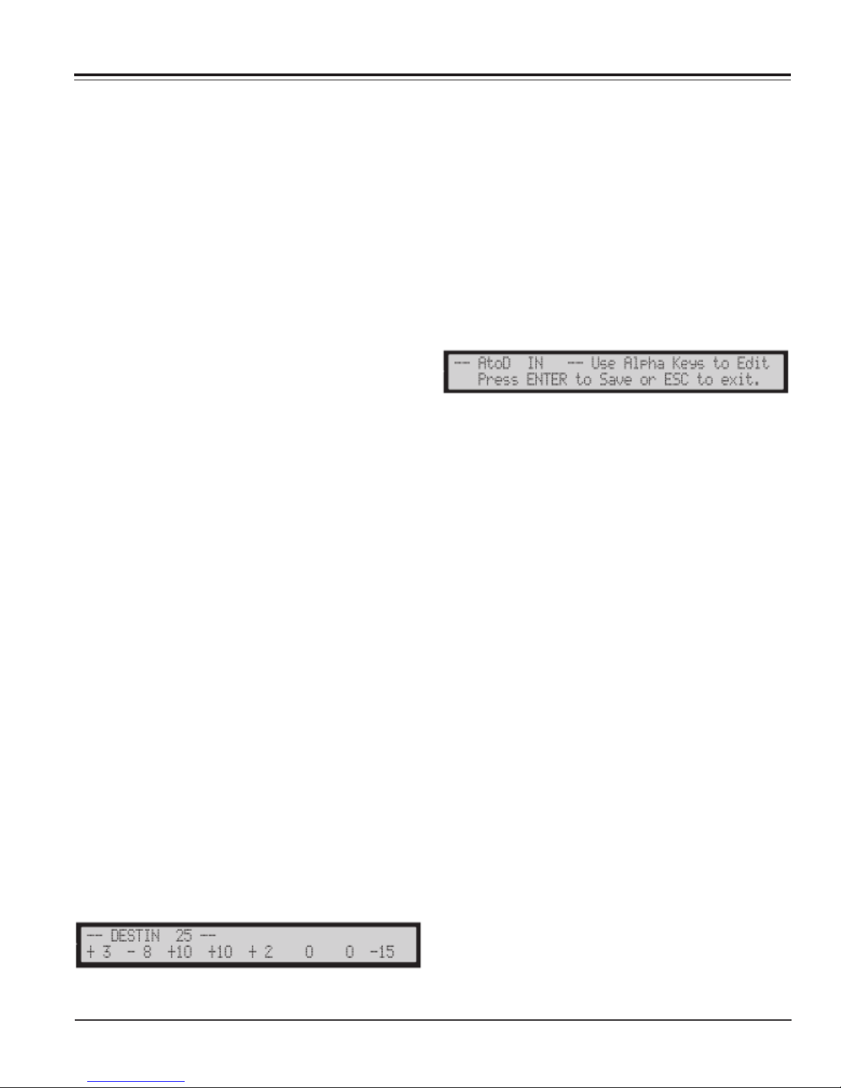
Appendix A: Controlling the SixtyFour from MotorMate
The red “source” LED indicates that the channel BURN
switches are the Source selectors for the SixtyFour.
Press any of the 8 BURN switches and its LED will light
to show that a source has been selected. The Source
Labels will appear on the top row of the LCD, and the
Source level will be on the bottom row.
Press the ROUTERS switch again and the yellow “destin”
LED will light. Now you are dealing with the destination
outputs on the SixtyFour.
The top row of the LCD will display the Destination
labels. The bottom row of the LCD shows the Destination
level settings. Stereo Destinations will show level and
stereo balance from Left 99 to Right 99. The 8 rotary
pots now control the destination levels and stereo
balances. Any Destinations that are routed to the
previously selected Source will light to show that they are
routed to that Source.
When the “source” or “destin” Burn Mode LED’s are on,
the upper panel of MotorMate no longer controls the
DAW, although the channel Mute and Solo switches still
control the DAW.
The lower panel of MotorMate continues to operate the
DAW as normal except for the SHIFT, DEFAULT, SAVE,
ON LINE, ENT and ESC. These exceptions are
described later.
To exit SixtyFour operations, and return the upper panel
to DAW operations, press the MIXER, PREAMPS or the
STEREO/SURRND switch. If there are any pending
operations on the SixtyFour, they must be completed
before exiting.
Creating LCD Channel Labels
Whenever the “source” or “destin” LED’s are lit, the Sixty
Four Source or Destination labels appear on the top row
of the LCD on MotorMate. These labels are stored inside
each SixtyFour device. The SixtyFour comes with
Source labels already defined as Source 01, Source 02
etc. The Destination labels already defined as Destin 01,
Destin 02 etc. Each label is 10 characters long.
Viewing Un-truncated labels
The LCD shows the first 2 and last 2 characters of each
label. Press and hold any channel SELECT switch (just
below the LCD) on MotorMate, and all 10 characters of
that channel will appear on the top row of the LCD.
Editing Labels
To edit a label, first press and hold down the ON LINE
switch on MotorMate and then press a SELECT switch to
begin editing that label. Its label will appear on the top
row of the LCD. Use the upper panel switches to enter
the desired name. The left and right View switches move
the edit cursor, and the decimal point switch (MUTE
switch on channel 8) functions as a space key. To
capitalize a letter, press SHIFT down first.
You can also access a pre defined device list by pressing
the View Stick up or down.
To abort the edit, press the ESC switch or press ENT
switch to save the label inside the SixtyFour.
Mono Source and Destination Labels
These can be labelled any way you like, but remember
that most of the time they will be truncated on the LCD,
so make your selection accordingly.
Stereo Source and Destination Labels
Use the same name for the left and right channels of a
stereo pair, but add a /L (a slash and a capital L) as the
last two characters for the left channel, and a /R (a slash
and a capital R) as the last two characters for the right
channel.
Note that you must also define Left and Right pairs in the
SixtyFour utility mode as defined in the SixtyFour owners
manual.
Surround Destination Labels
The Surround outputs on the SixtyFour should be set up
in the following order: Left channel, Right channel,
Center channel, Left Rear channel, Right Rear channel
and Subwoofer channel. They must be on adjacent
Destination outputs on the SixtyFour. For example
Destination outputs 22, 23, 24, 25, 26 ,27 could be the 6
surround channels.
You can assign all 6 labels automatically by the following
procedure. Assume that you want to assign your
surround outputs to be on Destinations 25, 26, 27, 28, 29
30.
Step 1. Press the ROUTERS: switch until the “destin”
LED is lit.
Page 30 CM Labs MotorMate Owner’s Manual
Step 2. Press the “VIEW” switches until Destination 25
(shown as DE25) is on the LCD.
Page 31
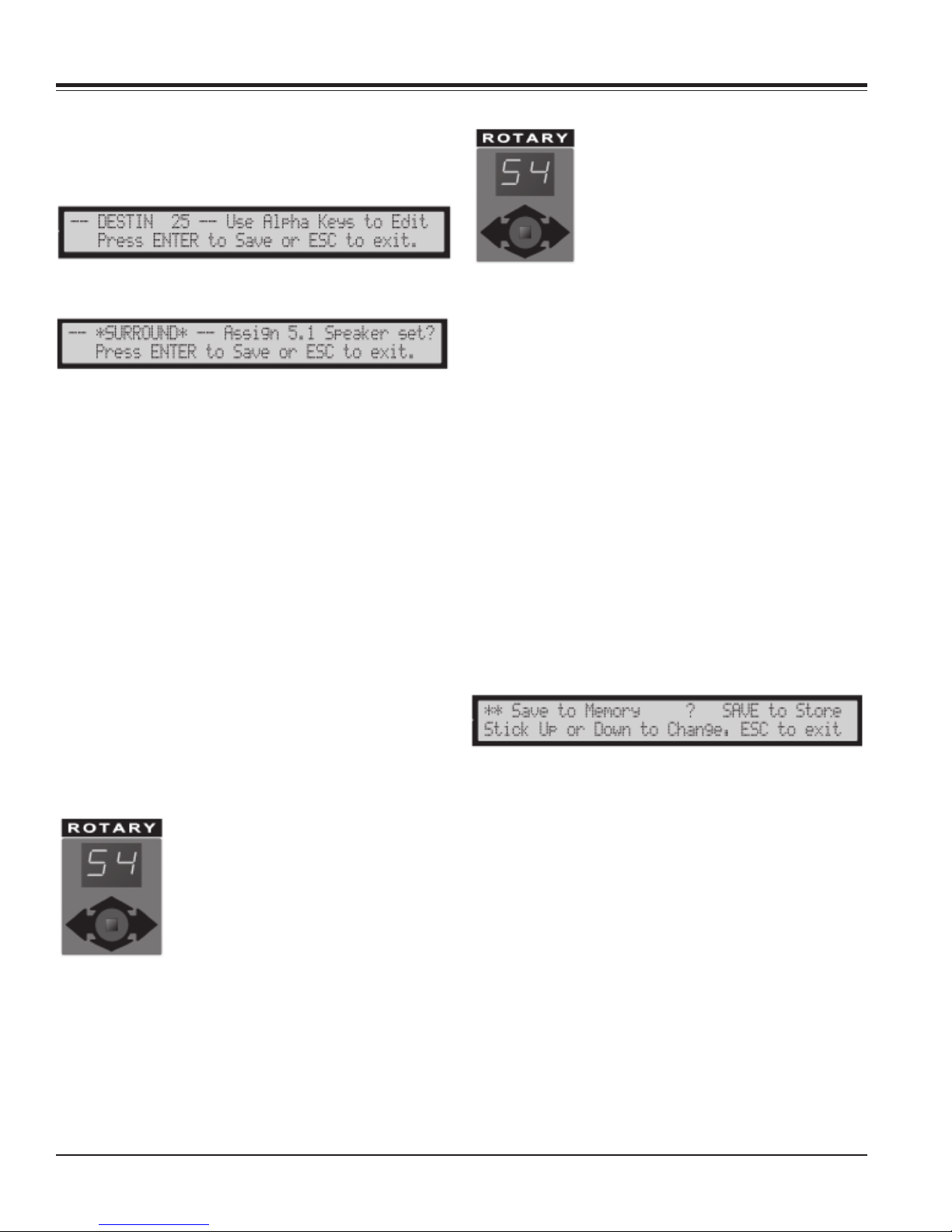
Appendix A: Controlling the SixtyFour from MotorMate
Step 3. Press and hold down the “ON LINE” switch on
MotorMate and then press the SELECT switch just under
Destination 25.
You will now see this on the LCD:
Step 4. Press the View Stick down once and you will see
the following:
Step 5. Press “ENTER” on MotorMate, and the Surround
outputs will be labelled and assigned:
Destin 25 Left *S
Destin 26 Right *S
Destin 27 Center *S
Destin 28 LRear *S
Destin 29 RRear *S
Destin 30 Sub *S
You can enter your own labels for the Surround outputs,
but they must be in the order listed above, and you must
use an *S (an asterisk and a capital S) as the last two
characters for the Destination labels of a Surround
device.
It is this *S that lets MotorMate know that a Surround
device is being sourced from the SixtyFour. When
Surround Monitor mode is selected on MotorMate it will
know how to deal automatically with the outputs.
Memory Operations
Recall
Push in the View Stick and the Memory
display will flash on and off. While it is
flashing, push the View Stick up or down
to scroll to new memories. As the new
memory numbers appear the settings of
that memory are “previewed” on
MotorMate.
The memory is not recalled until the View Stick is pushed
in again. The levels are previewed on the lower row of
the LCD. If the “destin” LED is on, the channel BURN
LED’s preview routing to the currently selected source.
The BURN LED’s light if they are routed to the selected
source. The LED’s will be off if they are not routed to the
selected source.
When the memory number is flashing, push in the View
Stick to recall a memory. If you wait 5 seconds, the
previous memory number will appear and no recall
occurs.
Save
The decimal point on the 2 digit Rotary Display will blink
on and off whenever the current settings of the SixtyFour
have been altered and are not the same as the current
memory. The far right decimal point also blinks on the
SixtyFour under these conditions. To save the settings,
press the SAVE switch on MotorMate, and push up or
down the XYZ View stick to select a location to store the
setting.
Press SAVE again to store them, or press ESC or push in
the Rotary Selector to exit without saving.
Each SixtyFour router has 90 user
memories to store Source and
Destination routing and levels.
Whenever a SixtyFour router is on line,
the 2 digit rotary mode display on
MotorMate shows the current memory
selected on the SixtyFour. This number
also appears on the SixtyFour display.
Undo
The decimal point on the 2 digit Rotary Display blinks on
and off whenever the current settings of the SixtyFour
have been altered and are not the same as the current
memory. To undo the changes, push in the View Stick.
When the memory number begins to flash, push in the
View Stick a second time, and the original memory will
be recalled and the decimal point will stop flashing.
CM Labs MotorMate Owner’s Manual Page 31
Page 32

Appendix A: Controlling the SixtyFour from MotorMate
Source Controls
Source Selection Operations
Mono Source Selection
When the “source” LED is lit, use the channel BURN
switches to select sources for routing. If the selected
Source is Mono, the channel BURN LED will illuminate to
show that it is selected. The Source level in dB will be
displayed below each source label.
Stereo Source Selection
Press either channel BURN switch of a stereo Source to
select it for routing. Both channel BURN LED’s will
illuminate to show that it is selected. Note that Stereo
pairs must be defined in the SixtyFour’s utility mode as
described in its owners manual. For Stereo Sources, the
level will be displayed below the left channel label. The
area below the right channel will be blank.
Destination Controls
Destination Routing Operations
Routing Mono Sources to Mono, Stereo Destinations
With the BURN switches in “source” mode, press a
BURN switch for the desired mono source that you want
to route. Press the ROUTERS switch to light the “destin”
LED. The channel BURN LED’s will light if they are
routed to the selected source. To route or unroute
destinations, press a channel BURN switch. If the
Destination is stereo, both BURN LED’s light to show that
it is routed to the mono source.
Routing Stereo Sources to Stereo Destinations
With the BURN switches in “source” mode, press the
BURN switch for the desired stereo source that you want
to route. Press the ROUTERS switch to light the “destin”
LED. The channel BURN LED’s will light if they are
routed to the selected source.
To route a stereo destination, press the left channel
BURN switch. Both BURN LED’s light to show that it is
routed. Once routed, you can press either left or right
BURN switch to unroute it.
Source Level Control Operations
Setting Source Levels
Rotate a channel rotary pot to change a Source level.
Source levels can be changed independently of which
source is selected. Stereo Sources have their level
displayed under the left channel label. The right channel
is blank.
Setting Levels to Unity
Press and hold the “DEFAULT” switch. Press any
channel SELECT switch, and the Source level will jump
to unity.
Setting Levels to Off
Press and hold the ALL switch and then press any
channel SELECT switch, and the Source level will jump
to off.
Cross-Routing Stereo
If you press the right channel BURN switch, the output
will be “cross-routed” with left going to right and right
going to left. The left channel Destination LED’s blink on
the SixtyFour to show that it is cross routed.
Surround Routing
Surround Sources must be routed one channel at a
time. Each individual Source driving a surround
Destination must be routed individually. This provides a
great deal of flexibility in working with multiple surround
Sources. For example, suppose you want to have your
ProTools outputs 3 through 8 (PT 03 - PT 08) source the
Surround outputs.
Route:
PT03 to Left *S
PT04 to Right *S
PT05 to Center *S
PT06 to LRear *S
PT07 to RRear *S
PT08 to Sub *S
Destination Level Control Operations
Page 32 CM Labs MotorMate Owner’s Manual
Setting Destination Levels
Rotate a channel rotary pot to change a Destination
level. Destination levels can be changed independently
of which source is selected and whether the Destination
has been routed or not.
Page 33
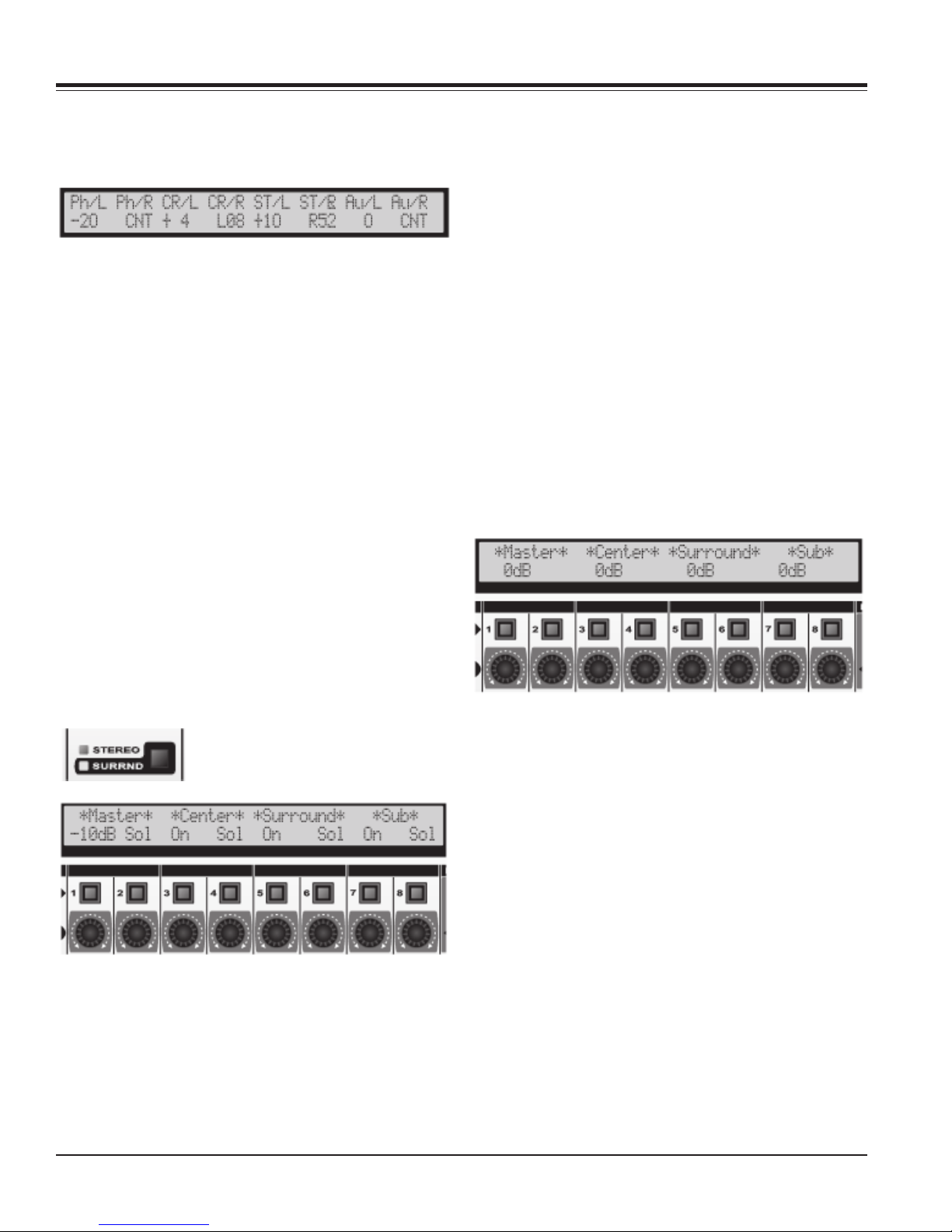
Appendix A: Controlling the SixtyFour from MotorMate
Stereo Destinations have their level displayed under the
left channel label and their stereo balance displayed in
the right channel. The left pot controls the level, and the
right pot controls the stereo balance.
Setting Levels to Unity
Press and hold the “DEFAULT” switch. Press any
channel SELECT switch, and the Destination level will
jump to unity. If the Destination is stereo, the left channel
SELECT switch will set the level to unity, and the right
SELECT switch will set balance to center.
Setting Levels to Off
Press and hold the ALL switch and then press any
channel SELECT switch, and the Destination level will
jump to off. If the Destination is stereo, the left channel
SELECT switch will set the level to off, and the right
SELECT switch will set balance to center.
Setting Surround Levels
Before you set Surround levels, you must first set up
your Surround labels as described earlier. Additionally,
use the SixtyFour to route the desired sources to drive
the Surround outputs. It is helpful to always have one of
the SixtyFour’s memories programmed this way so that
every time you want to monitor in Surround, you can
simply recall that memory.
If it still does not appear, then press “SHIFT”, “UNDO”
and “ENABLE” together to reset MotorMate and try
again.
Rotary Pot 1 is the Surround Master level control, and
can be set anywhere from +10dB to -96dB. This setting
is saved in the MotorMate’s nonvolatile memory, so it will
be recalled when MotorMate is powered on.
The SELECT switches control the Surround outputs as
follows:
SELECT 1: Surround Master on/off.
SELECT 2: Solo the Left and Right front channels.
SELECT 3: Center channel on/off.
SELECT 4: Solo Center channel.
SELECT 5: Left Rear and Right Rear channels on/off.
SELECT 6: Solo Left Rear and Right Rear channels.
SELECT 7: Subwoofer channel on/off.
SELECT 8. Solo Subwoofer channel.
Surround Channel Offsets
Press in and hold the XYZ View stick and the LCD will
First, recall a memory that has the Surround outputs
routed to the Surround Sources.
Then, press the STEREO/SURRND
switch until the “SURRND” LED
lights. The LCD will then appear as:
At the far left on the bottom row is the overall (Master)
level of the surround outputs. If this number does not
appear, then check the RS-232 cable connected to the
SixtyFour and that it is powered on. Recheck the
Destination labels to see that they are done properly.
Defaulting Surround Master Level to Unity
Press and hold DEFAULT, and then press SELECT 1 to
set the Surround master to unity.
appear as below:
You can use these offsets to make adjustments in the
Center, Rear, and Subwoofer channels for auditioning
purposes. The rotary pots adjust these in this manner:
Rotary pot 3 Center channel offset.
Rotary Pot 5 Surround (Rear) channel offset.
Rotary pot 7 Subwoofer channel offset.
These offsets are saved in the MotorMate nonvolatile
memory, so they will be recalled when MotorMate is
powered on.
Defaulting Offsets to Unity
Press and hold the View Stick and press a SELECT
switch to set that offset to unity.
If the sources that are routed into the Surround channels
are not all set to the same level, those will affect the
output levels in addition to the offsets. It is probably best
to set all the source levels to the same value to avoid
confusion.
CM Labs MotorMate Owner’s Manual Page 33
Page 34

CM Labs MotorMate Owner’s Manual
 Loading...