

CM Labs Sixtyfour Owner's Manual
Owner’s Manual
12/29/03
http://www.cmlabs.net

Legal Notice
Table of Contents
Notice:
Please return your warranty card immediately. Your
name will be placed on our E-mailing list (unless you
request otherwise) and we will inform you of all product
updates as well as new product developments. Some of
these updates will be free, so please return the card.
CM Labs reserves the right to make improvements or
changes at any time to the products described in this
manual.
Published by:
CM Labs
13221 191st Ave. S.E.
Monroe, WA 98272
U.S.A.
http://www.cmlabs.net
cmfluteguy@earthlink.net
Copyright © 2001 CM Labs™
All rights reserved
Operations:
Soft Lock .......................................................... 6
Autoscanning .................................................... 6
Unlocking .......................................................... 6
Memory Recall .................................................. 6
Route Mode ....................................................... 6
Level Mode ........................................................ 7
Meter Mode ........................................................ 7
Utility Mode ........................................................ 7
Patch Map ......................................................... 7
Stereo Pairs ....................................................... 8
Master / Slave .................................................... 9
Meter Sensitivity ..................................................9
Audio Interconnect & Quickstart ......................... 4
Pinout ................................................................ 4
Quickstart .......................................................... 4
Troubleshooting ................................................. 4
Audio Block Diagram ......................................... 5
Front Panel Controls ......................................... 5
Locks .................................................................. 9
Save ................................................................... 9
Undo ................................................................... 9
Multi Unit Control ............................................... 10
Specifications .................................................... 11
Creating Labels ................................................. 12
GPI Input .......................................................... 12
Serial Control Specifications .............................. 14
CM Labs SixtyFour Owner’s Manual Page 3
Installation & Quickstart
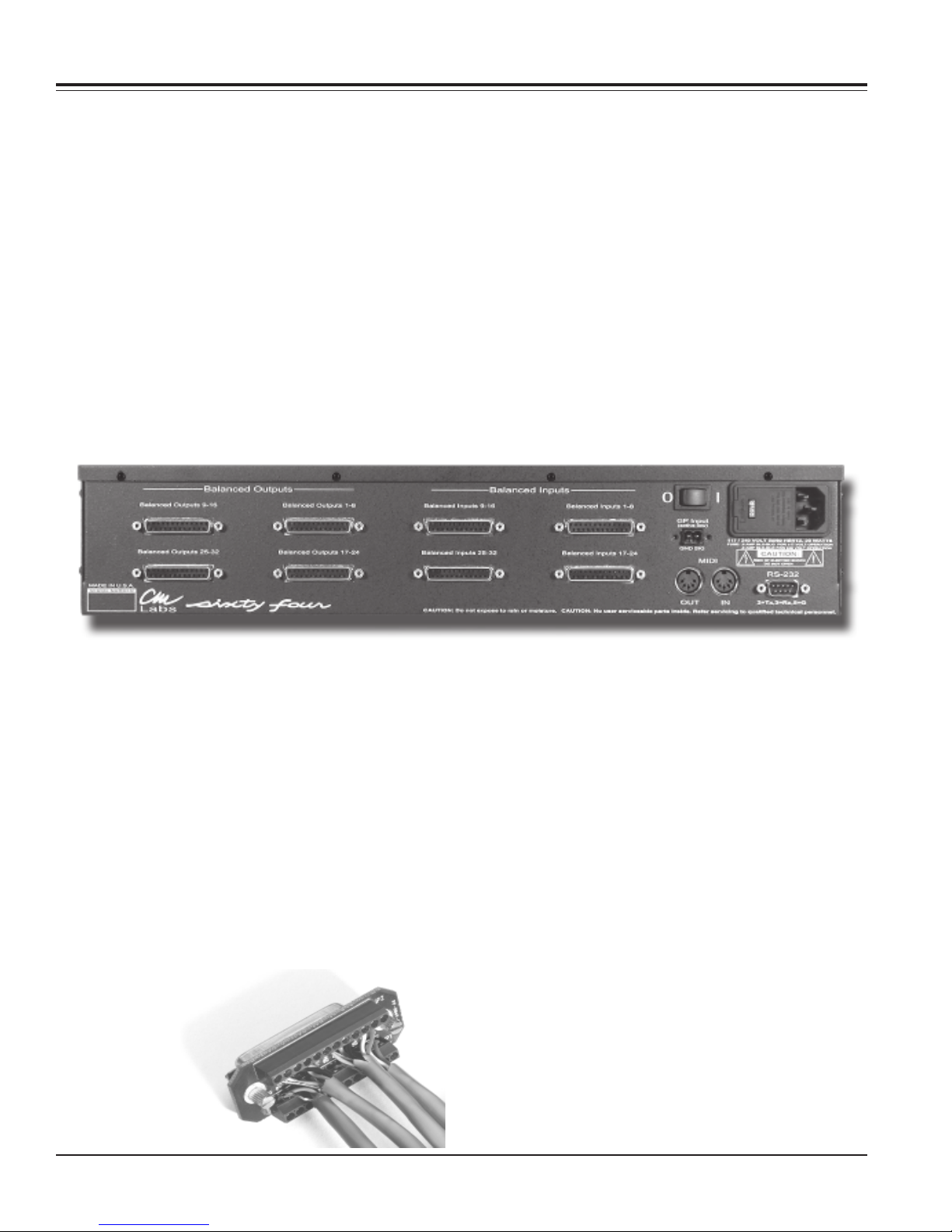
Audio Interconnect.
The SixtyFour has 8 DB25 female connectors on the rear
panel for all the audio inputs (sources) and outputs
(destinations). Each DB25 connector carries 8 balanced
audio inputs or outputs. Connect your audio devices to
the SixtyFour by 2 methods.
1.) Standard DB25 audio snakes. Simply connect the
snakes to the SixtyFour rear panel and tighten the screws
included with the snakes. Each DB-25 connector is fully
compatible with “Tascam” style snakes and connectors.
2.) The CM Labs DB-8 terminal strip adaptor. Wire the
DB-8 up according to the pin connections given on it.
Quick Start.
1.) Power on the SixtyFour. Both the “SAVE” and
“ROUTE” LED’s will blink in unison to show that it is “Soft
Locked”.
2.) Press the SAVE and ROUTE switches together to turn
soft lock off.
3.) Press in the Encoder and rotate until it says “P 5” and
release it. You have just recalled memory # 5. The
memory is not actually recalled until you release the
encoder.
4.) Press the ROUTE switch to enter route mode. Press
SOURCE 3 switch to select source 3.
5.) Press DESTINATION 1 switch. You have just routed
source 3 to destination 1. You will notice that the decimal
point is blinking to indicate that the current settings are
different from memory # 5.
Use the (+) and (G) connections to hook up single ended
(unbalanced) devices to the SixtyFour. Since the
SixtyFour has gain control, you can level match unbalanced to balanced devices.
Pinout:
Channel Pin Signals
1 , 9 , 17 , 25 24 ,12 , 25 + , - , GND
2 , 10 , 18 , 26 10 , 23 , 11 + , - , GND
3 , 11 , 19 , 27 21 , 9 , 22 + , - , GND
4 , 12 , 20 , 28 7 , 20 , 8 + , - , GND
5 , 13 , 21 , 29 18 , 6 , 19 + , - , GND
6 , 14 , 22 , 30 4 ,17 , 5 + , - , GND
7 , 15 , 23 , 31 15 ,3 , 16 + , - , GND
8 , 16 , 24 , 32 1 ,14 , 2 + , - , GND
CM Labs DB - 8 audio adaptor
6.) Push in the encoder, and notice that all the routes you
made were just undone.
7.) Press the LEVEL switch to enter level mode. Press
SOURCE 1 switch to select source 1. The display now
shows the level setting (in dB Gain) for source 1.
8.) Rotate the encoder to change the level setting of
source 1.
9.) Press DESTINATION 1 switch to select destination 1.
The display now shows the level setting (in dB Gain) for
destination 1.
10.) Rotate the encoder to change the level setting of
destination 1.
Troubleshooting
If your SixtyFour does not respond properly please Email
us at cmfluteguy@earthlink.net and let us know the
nature of the problem and your phone number. We’ll do
our best to get you going in a hurry.
Page 4 CM Labs SixtyFour Owner’s Manual
Installation & Quickstart
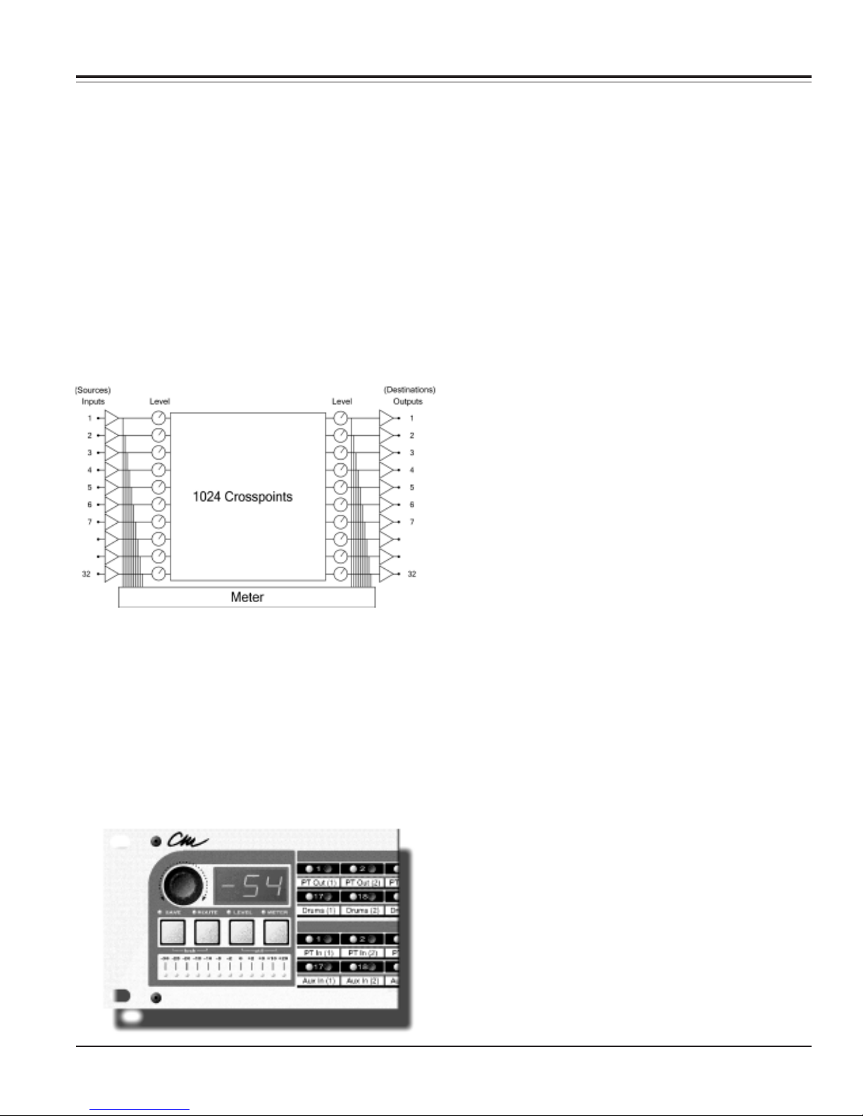
Audio Block Diagram.
The diagram below shows how audio signals are dealt
with inside the SixtyFour.
The audio inputs are buffered and sent both into a level
control element and a meter input. This meter point
meters exactly what is coming into the SixtyFour from
the outside world. The signal then passes into a level
control element and then into the 1024 point switch. This
switch does all the routing inside the SixtyFour.
Coming out of the 1024 point switch, audio is sent to a
level control element and then to the output buffer and
meter. The output meter shows what is coming out the
SixtyFour outputs. If you have a level turned down or an
output unrouted, the meter will show this.
Source Switch Field.
Each input channel (source) has a switch to select it.
Only one source can be activated at one time. When
working with STEREO sources you will select sources as
pairs. When a yellow source LED is lit, it indicates a
selected source.
Destination Switch Field.
Each output channel (destination) has a switch to select
it. When working with STEREO destinations, you will
select them as pairs. When a red destination LED is lit, it
indicates a selected destination.
Save.
This switch, when pushed is used to activate SAVE mode
to store current settings defined by the user. You have 90
different program memories.
Route.
This switch activates ROUTE mode and is used to
determine the routing of a source to desired destinations.
Level.
This switch activates LEVEL mode and is used to adjust
source and destination levels.
Front Panel Controls.
There are 3 audio functions of the SixtyFour. They are
Route, Set Levels, and Meter signals. The “Route”,
“Level”, and “Meter” switches control these 3 functions.
There are 32 “Source” switches each with a Yellow LED,
and 32 “Destination” switches each with a Red LED.
These switches are used to select your audio sources
and destinations while performing these 3 functions.
Meter.
This switch activates METER mode and is used to verify
audio signal strength of sources and destinations.
Encoder.
Used to select program memories (save, undo and
recall), set source and destination levels, adjust all
system parameters.
Numeric Readout.
Displays: Program memory, source/destination level
setting, stereo balance and system parameters such as
device number.
CM Labs SixtyFour Owner’s Manual Page 5

Operations
“Soft Lock”.
The SixtyFour powers on with “Soft Lock” on. The two
yellow LED’s above “Lock” & “Save” will be flashing
indicating the unit is “Soft Locked”. The SixtyFour also
has several other lock features that are described in the
Utility portion of this manual.
Operations available while
“Soft Lock” is engaged.
1. Pushing a source or destination switch will show
routing already assigned.
2. You can see source levels or destination levels and
stereo balance settings. Press the LEVEL switch to enter
level mode. Now choose the source or destination you
wish to examine. To see destination stereo balance, push
in the encoder.
3. You can meter a source or destination. Press the
METER switch to enter METER mode. Now choose the
source or destination you wish to examine.
Autoscanning.
Autoscanning can be done with “Soft Lock” on or off.
Autoscan provides quick review of current routes, levels,
or audio amplitudes. Press and hold the ROUTE, LEVEL
or METER switches for more than one second to begin
the scanning. Control the speed of scanning with the
rotary control knob. To stop the scanning, press the
ROUTE, LEVEL or METER, SOURCE or DESTINATION
switch.
Unlocking the SixtyFour.
In order to recall from, or save to memory, route, set
levels or access utility mode, you first must “unlock” the
SixtyFour. To unlock, simply press the two switches
labeled “Save” & “Route” at the same time. Notice that
just below these two switches, the graphic labels the pair
as “Lock”. (When you are ready to lock the unit, simply
press the same two switches. The LED’s above “Save” &
“Route” will now flash indicating the “Soft Lock” is back
on.)
Memory Recall.
1. Push in the encoder knob, and the letter “P” will appear
on the display, and the current memory number will flash
on and off.
2. Rotate the encoder to scroll through the memories.
During this scrolling, none of the audio routing or levels
are changed. The panel of the SixtyFour is updated to
show the routes or levels in the memory, but no actual
recall occurs.
3. To select the memory and recall the settings, push in
the encoder. The “P” will dissapear, and the patch
number will light solid. The routing, level settings, and
Patch Map will all be recalled.
4. If you do not push in the encoder the second time, after
about 4 seconds you will return to the original memory
number, the “P” will dissapear, and the original patch
number will light solid.
Route Mode.
1. With “Soft Lock” off, press the desired source switch.
The source yellow LED will light up indicating that source
is selected.
2. Choose all intended destinations for that source by
pressing destination switches. The Red destination LED’s
will light to show the destination is routed to the current
source. You may choose as many destinations as
necessary to assign to a source.
3. Repeat this procedure for each source. You may not
combine multiple sources at the same destination. In
order to have multiple sources combine at a common
destination, you will have to install a remote mixer at the
output.
Note: If you route a destination which is already routed to
another source, it will be automatically unrouted from
that source before it can be routed to the current source.
If you want to undo the routing changes made, press the
rotary control knob, the original routing choices will be
restored.
Routing Stereo.
1. Enter Route Mode .
2. Choose a stereo source. It does not matter which of
the two source switches you push.
3. Push the left switch of the stereo destination pair to
create a left to left/right to right route (both LEDs will glow
steadily). Push the right switch of the stereo destination
pair, the left switch LED will start flashing to indicate a
left to right - right to left route.
Note: If the current settings have been changed since a
memory was recalled, the right most decimal point will
flash on and off. Pushing in the encoder will undo these
changes first, before you can recall from memory.
Page 6 CM Labs SixtyFour Owner’s Manual
Routing Undo.
You can undo any routing changes at any time before
saving by simply pressing the encoder knob to revert to
the previously saved setting.

Level Mode.
Audio levels can be addressed for both source and
destination. Source level changes affect all destinations
routed to that source. Destination level changes only
affect the destination (specific). You can change the level
on only one source or one destination at a time. You can
undo any level changes at any time before saving. Simply
press the encoder knob to revert to the previously saved
setting.
Source Levels.
1. Unlock the SixtyFour and select a source to be
adjusted by pressing the appropriate source switch.
2. Then press the LEVEL switch on the front panel. The
numerical display will show the current source level in
relative decibels from -96 to +10.
3. Rotate the encoder knob to set the level. Note that by
simply rotating the encoder knob you will change levels
in 1 dB increments. By pressing and rotating the encoder
knob, levels will change in 10 dB increments for mono
destinations.
Destination Levels.
1. WIth the SixtyFour unlocked and in LEVEL mode,
select a destination to be adjusted by pressing the
appropriate destination switch. The numerical readout
will indicate current level for that destination.
2. Rotate the encoder knob until the desired level is
chosen. Note that by simply rotating the encoder knob
you will change levels in 1 dB increments. By pressing
and rotating encoder knob, levels will change in 10 dB
increments.
Stereo Balance.
If a stereo source or destination is selected, press and
hold in the encoder knob while rotating it to adjust stereo
balance between left and right channels of a destination.
Operations
-30 -25 -20 -15 -10 -5 -2 0 +2 +5 +10 +
Utility Mode.
Utility menu choices are:
A. Create Patch Map.
B. Create Stereo Pairs
C. Set Master/Slave
D. Set Device Number
E. Set Locks.
WIth Soft Lock off, press both LEVEL & METER switches
at the same time. Both LED’s above the switches light to
indicate you are in utility mode.
Each time you press and then release the rotary control
knob, the next menu selection will appear in the
numeric display.
A. Create Patch Map.
Shows as NAP in numeric display. Sources #1 - 16 will
begin flashing. Each source light corresponds to a MIDI
channel.
1. Press source button #1 and the numeric display will
show its status.
2. If “Off”, press rotary control knob to turn on. Rotate the
knob until the desired MIDI command appears in the
numeric display.
4. Go on to Source #2 and repeat the assignment
procedure. Once you have made all your assignments,
save this information before exiting utility mode.
*Note: If there is a blinking period in the lower right-hand
corner of the numeric display once you have exited utility
mode, it means you have changed the patch map but
have not yet saved the change. You will loose any
changes at this point if the unit powers down for any
reason and you have not executed the save function.
Meter Mode.
Metering can be addressed for both source and
destination. You can meter only one source or one
destination at a time.
When you are monitoring a source, you are seeing the
raw input signal before any control of levels. When you
are monitoring a destination, you are seeing the
final result of all routing, and level settings (see block
diagram).
1. To monitor a source or destination, choose the desired
source or destination first.
2. Now press the control button labeled “meter”. the
display will now give the readout for that choice.
If source or destination is stereo, meters only reference
one channel at a time.
CM Labs SixtyFour Owner’s Manual Page 6
 Loading...