

Page 1

CMI | SOP003_rev1.0
1
CMI STANDARD OPERATING
PROCEDURE
Confocal Raman Microscope
Physiology Ground floor research lab
CONTACT
Peter Owens: 091 494036 (office) Peter.owens@nuigalway.ie
Jennifer Connolly: Jennifer.connolly@nuigalway.ie
REQUIREMENTS FOR EQUIPMENT USAGE:
1. CMI user
2. Completion and signing of Microscope Safety Checklist
3. Certification by Peter Owens or Jennifer Connolly
REVISION LOG
INFORMATION:
CMI document ID: SOP003
Revision
1.0
Date
12/5/14
1. Purpose
1.1. This document specifies the work instructions for the CMI Witec Confocal Raman microscope located in
the ground floor Physiology lab, Quadrangle building. If you see an area where more clarification is
needed, if additional information is needed, or if you have suggestions on how to make this guide more
1.2. Note that this document is not a detailed instrument manual and does not intend to be one. For
useful in the lab, please contact the CMI.
detailed questions or if anything unusual happens with the system, please refer to the manuals
present in the lab, or ask CMI personnel for help.
Author
P. Owens
Changes
Initial draft
Page 2
CMI | SOP003_rev1.0
2
2. Scope
These work instructions are applicable to all work that is carried out using the Witec raman microscope.
3. Important notes
3.1 Laser safety guidelines
PLEASE LEAVE ALL HARDCOPIES IN THE LAB
The WITec microscopes uses class 4 633 and 785 nm laser sources during operation. The
safe use of lasers requires that all laser users, and everyone near the laser systems, are aware of the
dangers involved.
CAUTION: Direct eye contact with the output beam from a laser will cause serious damage and possibly
blindness. The 785 nm laser has a high power output, extreme care is needed here when operating the
system.
3.1.1 Make sure the enclosure remains closed during laser scanning and measurement
3.1.2 Always close the laser shutter before opening the door of enclosure
3.1.3 Always wear the safety laser goggle when you want to open the door with laser on for
alignment procedure.
3.1.4 Participation in a Laser safety course is strongly recommended for operating this system.
3.2. Witec Alpha 500 manual (hardcopy in the lab, soft copy on the instrument PC), and training notes
3.3 The CMI access policy, available online at
http://imaging.nuigalway.ie/access%20policy/cmi_access_policy_1.6.pdf
3.4 This manual was developed to assist in the training process of users. Be aware that only the basic
operation details will be presented. Please contact the CMI staff for more assistance if required.
3.5 Changes may occur when a new software version or patch is installed. Please contact the CMI
staff if you are not sure about new features and functions.
3.6 Do not forget to sign in to the log book before you start your measurement.
3.7 Turn on the laser power when you begin, use laser shutter in-between measurements.
Responsibilities
4.
Operators of this equipment are responsible for the following:
4.1 Complying with all safety regulations.
4.2 Compliance with procedures and specifications contained in this document.
4.3 Reporting misuse of the instruments, or in a manner inconsistent with this specification, by any
Page 3

CMI | SOP003_rev1.0
3
personnel, to the supervising CMI staff.
4.4 Maintaining a clean workspace. Food and drink are NOT allowed!
4.5 Reporting any and all maintenance issues/concerns to the supervising CMI staff member
5 Raman overview
Raman spectroscopy is a characterization technique that is widely used in scientific field in recent years. It
actually utilizes the unique Raman spectra for different components as a spectral “finger print” to identify
unknown samples or even further analysis based on the information from the spectra. Raman spectra can be
obtained from various kinds of materials from bulk solids such as paper and cellphone, to nanomaterials such
as thin films and nanoconstructs.
Raman Spectroscopy has many advantages among many characterization techniques, and therefore it is quite
welcome in scientists and laboratory workers. Typically, the samples need little preparation before
characterization and analysis can be carried out through many containers. Raman Spectroscopy is usually not
destructive to samples unless you use too much laser power and focus high-energy laser on a point of the
sample, leading great amount of heat in that small area and thus burning your sample.
In addition, Raman Spectroscopy is typically a fast characterization technique that can perform real-time scan.
It can acquire a Raman spectrum of most substances in seconds via Charge Coupled Device detectors (CCDs)
that have a wide dynamic range for users to select the appropriate exposure time for their sample. Depending
on the raman cross section of the sample of interest, a high resolution scan can be finished in minutes using
the system.
Raman Spectroscopy can do both qualitative and quantitative analysis. Quantitative analysis of the sample is
typically performed by measuring the relative intensities of each peak in the Raman spectrum that are directly
proportional to the relative concentrations of the compounds. Alternatively, chemometric methods can be
used for detailed information and accurate calculation. These quantitative analyses are very sensitive that can
be performed on samples with high concentrations ranging from 90-100% material of interest down to
concentration determination at parts per billion (PPB) levels.
This instruction will guide you to run a Raman spectroscopy scanning step by step and help you obtain your
first Raman spectrum/ image from the WITec Raman Spectroscopy Instrument. It can also be used as a manual
book for laboratory users in case of operational problems and troubleshooting. This instruction is separated
into sections for instrument overview, step by step alignment and calibration check, acquisition, imaging, and
troubleshooting. Readers should follow the procedures in this instruction in order to operate the Raman
instrument properly.
DANGER: Class 4 laser radiation involved during the procedure!
immediately.
Page 4
CMI | SOP003_rev1.0
4
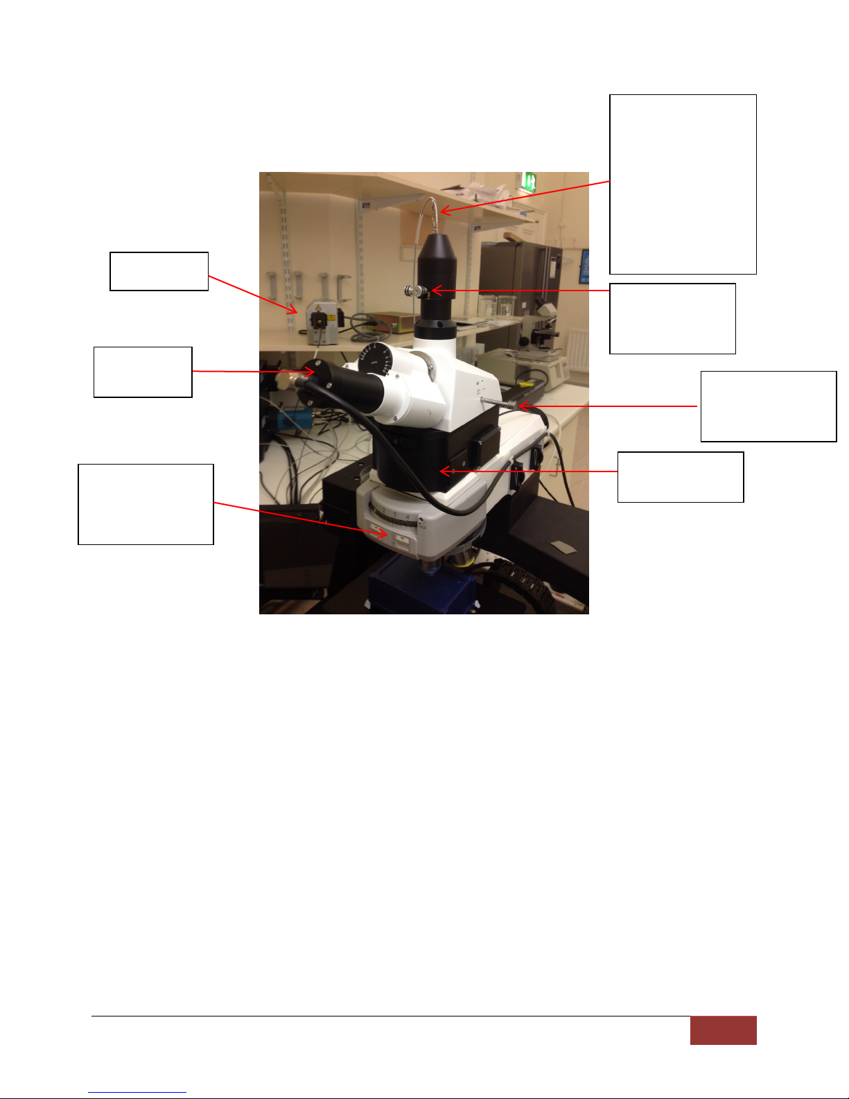
Fibre to detection
Adjustment
alignment
Push/pull rod for
Laser coupler
and filter wheel
Eye piece
camera
785nm laser
Brightfield/DIC/Ra
6 System Overview
man imaging
selection
system. Use 50 micron
fibre for 633 nm, 100
micron fibre for 785nm
excitation, fibre
diameter is part of the
serial number taped on
fibre. Extreme care
needed when handling
screws for
eyepiece/detector
The witec confocal raman microscope consists of the following devices:
6.1 Instrument Control PC, 64 bit running witec control and project software (version 1.6)
6.2 Controller unit.
6.3 Upright microscope with led light source for brightfield work.
6.4 Objectives including a 40x water dipping lens and 100 x air
6.5 Andor CCD cameras
6.6 Witec diffraction gratings for either vis or NIR operation.
6.7 Motorised stage for xyz control
6.8 Fibre optic cable for 633nm use: 50micron diameter
6.9 Fibre optic cable for 785 nm use : 100 micron diameter
Familiarise yourself with the system folders, located on the shelf above the equipment.
7 Start Up Procedure
7.1 Book equipment on CMI web booking system.
7.2 Turn on lasers or individual laser, if only one is to be used. For the 633 laser, turn on the key. For
the 785 nm laser, turn on power first and wait until the green led stops flashing. Then switch the
laser key to ‘on’ and again wait until the green led stops flashing and both yellow and green leds
Page 5

CMI | SOP003_rev1.0
5
are continuously on.
633nm laser
785 nm laser
Modulate
intensity
Diffraction grating
Diffraction grating
CCD camera VIS
CCD camera NIR
Power sockets for
Power to controller
tower
shutter
shutter
7.3 Turn on power to controller if not already on.
7.4 Turn on power to camera(s). Turn on only the one you are planning to use :
for visible spectrum
for NIR spect
camera, inner plug is
for NIR camera
7.5 Turn on PC, login password is ‘biophotonics119’.
7.6 Both the lasers have to be warmed up for at least 30 mins before acquisition; while warming up
alignment of the microscope can be done.
7.7 Click on the ‘Witec Project Control’ to start the raman software interface
laser
Page 6

CMI | SOP003_rev1.0
6
Laser coupler
Filter turret
imaging, spectra
8 Calibration
8.1 Use the silicon wafer for calibration (accepted Raman peak at 521 wavenumbers)
8.2 Choose objective to use and switch to brightfield mode (with edge filter and dichroic mirror off);
beam splitter should be in Bright Field (BF) mode (Pos 1)
Position 1: Brightfield
imaging
Slide rightwards(follow
arrow direction)
Options are block:
Position 2: DIC for
water dipping lens
Position 3: DIC for all
other lenses
Position 4: Raman
8.3 Set the detector knob, at the side of binocular, to the eyepiece mode (and not the camera mode)
8.4 Set the brightness to 100% in the software (‘Illumination’). Make sure to see some intensity
changes in the video image; check it by opening and closing the aperture stop (A) at the
microscope. Typically keep this just slightly open, unless for dim samples/dic imaging.
Open:
Either open , block for
633nm and 785 nm
can be chosen. All
other positions have
no filter , used for
brightfield.
Page 7

CMI | SOP003_rev1.0
7
Push/Pull rod
Eyepiece camera
Aperture stop
Field stop
Up/down: toggle
stage control
X Y Stage controls
Z Stage controls
Speed control :
Changing fibres: gently slide
the cover over the fibre and
rest on side of stand , ensuring
no kinks in fibre, unscrew the
fibre and change to the other
one. Align the raised edge on
the fibre coupling with the slot
on the fixed end then tighten
(hand tight-do not
overtighten)
Replace the black cover
Fully out : light directed to
detector system
Fully in : light directed to
eyepiece camera
8.5 Close the field stop and focus to bring the stage up
applies to either xy
or z. rotate white
circle anticlockwise
to reinitiate control
and increase by
rotating clockwise
8.6 With the remote, select ‘Microscope Z’ control and adjust the focus (in ‘z’); when in focus
between z control, xy
+Z : stage moves
away from objective
-Z: stage moves
towards objective
position, the image of the field stop is sharp in the video control window.
8.7 Fine tune the focus with remote observing the image of the field stop again.
8.8 Then open the field stop to observe the silicon sample.
Page 8

CMI | SOP003_rev1.0
8
8.9 Select the correct Video Viewer (objective) in the Video Control Window and calibrate (using
‘Video Calibration’ button). The rotation should be within -1 and +1 degree. If not, rotate the
camera in the binocular and redo the calibration. Hint: center a piece of dirt or scratch in the
video viewer window and try calibration again if having trouble getting the rotation below 1.
8.10 Turn the roller (at the Raman coupler) to needed laser wavelength (with edge filter off) and
switch on the shutter of the respective laser with minimum power. Adjust the laser power until
the laser spot can be seen in the video image. Move the microscope in ‘z’ to focus the laser until
the laser spot is sharp.
8.11 Select ‘Probe position’ on the laser spot.
8.12 Make sure the correct spectrometer is connected with the camera fibre and the right laser is
selected using the ‘Configuration’ in the taskbar
50 micron fibre : 633nm use
100 micron fibre : 785nm use
It is recommended to calibrate with silicon , if switching between wavelengths, but can be
possible as a quick check just to swap in the fibre cables. Note: Take extreme care when
handling the fibre cables as they can be damaged very easily. Ensure that the raised edge on
the fibre end lines up with slot on the connector before tightening.
8.13 Switch the coupler to laser wavelength with edge filter on.
8.14 Pull out the knob to ‘Camera mode’ (the light propagates through the detection fibre now).
8.15 Remove the beam splitter (set to either position 4) (not BF nor DIC or position 2 (extra DIC optics
filters in that position).
8.16 Start ‘Oscilloscope’, and adjust the power of the laser to get maximum intensity of the 1
Raman band of Silicon at ≈520 rel.cm
-1
st
order
8.17 Adjust fine focus.
8.18 Using the X and Y fibre knob (on top of the laser coupler), get the maximum intensity of the
Raman band; then again adjust the Z focus with objective.
8.19 Redo the above steps till maximum intensity is obtained.
8.20 Record the spectrum for silicon , say 0.5 integration time , verify that the peak intensity is as
expected and in the right place ie 520 rel wavenumbers.
8.21 Close the laser shutter and stop the oscilloscope. Alignment of the microscope is now completed.
Page 9

CMI | SOP003_rev1.0
9
Configuration
Project window all
Video
mode
Probe position
indicator
Data processing drag
Indication of z
Turn on
illumination
Hardware status window
Check
xy stage
Calibrate
button
Set probe
button
and click auto
brightness
speed of
9 Raman Measurements:
position
window
brightfield
display
video image
operations
performed during
the course of this
instance of the
software are stored
here. Rename all
files to meaningfull
names rather than
system generated
control conditions
only – doesn’t do
much
and drop operations
9.1 For in-vitro samples, the cells can be imaged with 633 nm laser and the nanoparticles with 785
nm laser. Saliva, to date has been recorded using 785 nm excitation.
9.2 After point scan or line scan to confirm the SERS signal from Raman reporter, an area of interest
is marked in the bright-field image.
9.3 Using ‘Sum’ filters, a spectrum region of interest can be marked; images specific to that range
will then be mapped by the WITec software. More than one range can be selected, and thus
more than one large area scan images can be constructed from a single large area scan. Eg, For
cells, vibrational bands of C-H stretching around 700 and 1000 wavenumbers can be used for
mapping.
9.4 After selecting the large area scan images with better contrast (between cells and nanoparticles),
data analysis – background correction, cosmic ray removal, basis analysis – can be performed on
large area scan data.
Page 10

CMI | SOP003_rev1.0
10
10 Troubleshooting
10.1 If you cannot see the laser spot – Check if the laser is turned on. Check if the shutter is open.
10.2 If you cannot see the white light – Check if the white light source is turned on (Illumination in
software. If it is turned on, then check if the microscope is set in Raman Mode. If it is in Raman
mode then change it to the eye-camera mode.
10.3 If you see the spectra with full of noise signal – Check for the CCD temperature. It should be
o
C .
-60
Procedure
Shut Down
11
11.1 You can save the experiment parameters for your own scanning recipe by clicking “Save
Project’ in ‘File’.
11.2 Close the laser shutter, switch off the laser power supply.
11.3 Using the remote control, move the sample away from the objective.
11.4 Open the doors. Remove the sample from the stage
11.5 Discard cover slips and glass sides in the red sharps container. This includes BioHazard material.
11.6 CLEAN UP the workplace, and leave it better than you found it.
11.7 Close the software, it will take several minutes to warm up the CCD before the software
fully closes. Log-off the computer. Log out from computer, complete log book.
Page 11

CMI | SOP003_rev1.0
11
12. APPENDIX A - CERTIFICATION: DEMONSTRATION OF SKILLS
Name:
Operation:
Date:
Tested by:
Pass:
Fail:
DEMONSTRATION of SKILLS
Demonstrate system/ software start up and configuration
Demonstrate loading a sample on the microscope
Demonstrate finding the sample, optimizing acquisition and taking spectra
Demonstrate changing the fibre cable during the measurement session
Demonstrate finishing and shutting down system
Where are cover slips, glass slides discarded?
Where are biological samples discarded?
Correct use of lasers and proper handling procedures?
Certification:
SAFETY
VALIDATION
Pass Fail
Trainee Certified by:
Date:
 Loading...