

Page 1
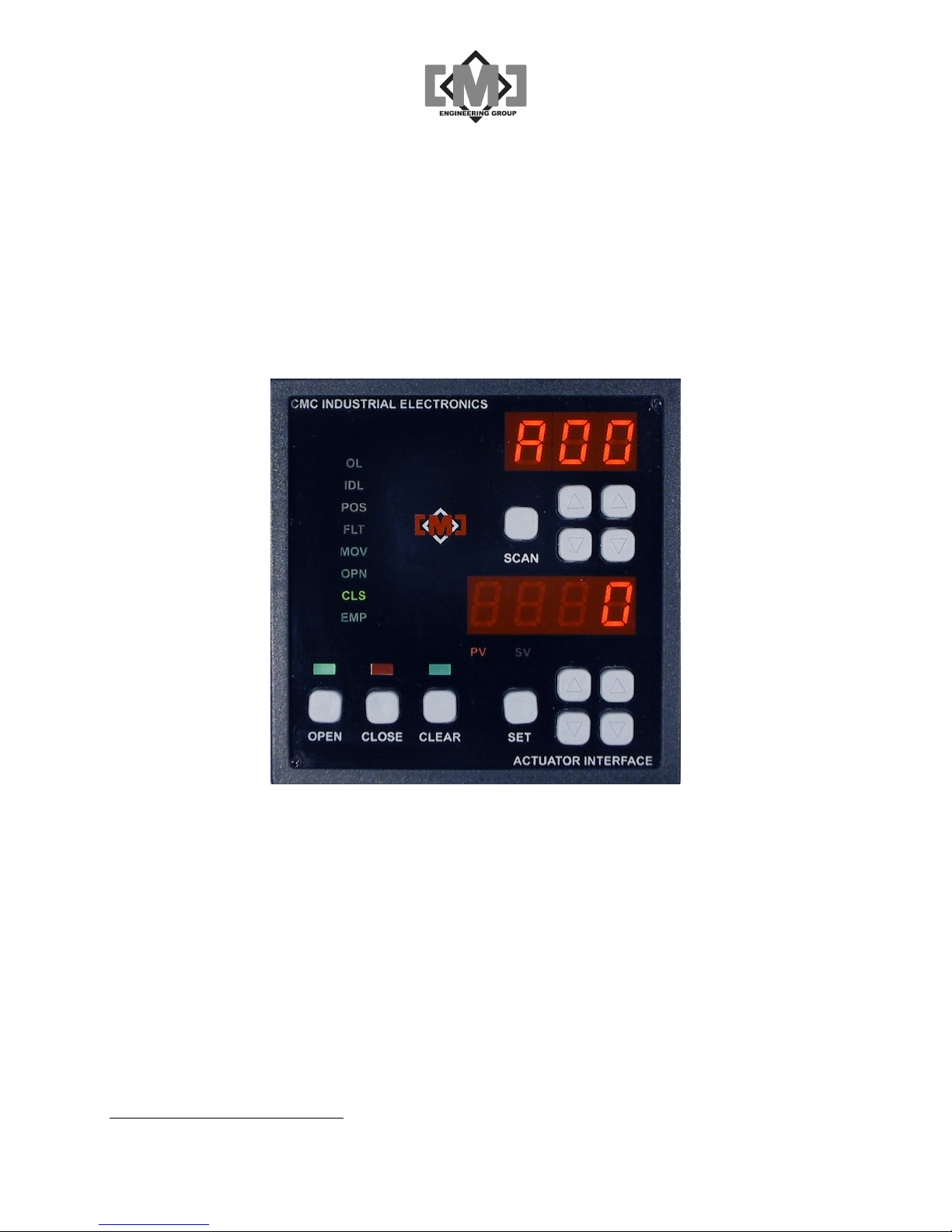
mAI085MB Actuator
Interface Technical Manual
Distributive Intelligence
Document No. 10856 Revision B
July 2007
1997-98-99, 2000 CMC Industrial Electronics Ltd.
Phone: (604) 421-4425 Toll-Free: (888) 421-4425 Fax: (604) 421-7734
CMC INDUSTRIAL ELECTRONICS LTD
[email protected] www.cmciel.com
Page 2

Page 3

mAI085-MB Actuator Interface Technical Manual /i
Table of Contents
1. Overview..............................................................................................................................1
2. Description of the Keypad and Indicators.............................................................................3
3. External Connections...........................................................................................................5
3.1 Power and Communications .........................................................................................6
3.2 Optional Extended Data Network..................................................................................7
4. Using the Interface...............................................................................................................9
4.1 Selecting an Actuator Controller ...................................................................................9
4.2 Changing a Setpoint .....................................................................................................9
4.3 Opening the Actuators ..................................................................................................9
4.4 Closing the Actuators....................................................................................................9
4.5 Clearing the Setpoints.................................................................................................10
5. Configuration .....................................................................................................................11
5.1 Overview of System Configuration..............................................................................11
5.2 Configuration Keyboard Functions..............................................................................14
5.3 Configuration Menus...................................................................................................15
5.3.1 Main Menu...........................................................................................................16
5.3.2 Local Menu ..........................................................................................................18
5.3.3 Actuator Controller Menu .....................................................................................18
5.3.4 Modbus Interface Menu .......................................................................................21
5.3.5 Factory Values Menu...........................................................................................22
5.3.6 Diagnostics Menu ................................................................................................23
6. The Input / Output System .................................................................................................25
7. Controlling Conveying Systems .........................................................................................27
8. Using the Modbus Network Interface .................................................................................29
8.1 The Modbus Serial Interface .......................................................................................29
8.2 Register Assignments .................................................................................................29
8.2.1 Read Only Registers............................................................................................29
8.2.2 Read-Write Registers ..........................................................................................31
8.2.3 mAI085-MB Special Registers .............................................................................31
9. Specifications.....................................................................................................................33
10. Appendix 1 - Editing Controller Setup Tables on a PC ...................................................35
10.1
Setting up HyperTerminal........................................................................................35
10.2
Downloading the Configuration to the PC................................................................37
10.3
Uploading the Configuration to the mAI085MB........................................................40
11. Appendix 2 - Drawings ...................................................................................................43
Distributive Intelligence
CMC INDUSTRIAL ELECTRONICS LTD
Page 4

mAI085-MB Actuator Interface Technical Manual /ii
Table of Figures
Figure 1 - Keypad and Indicators ................................................................................................3
Figure 2 - Terminal Blocks and Connectors ................................................................................5
Figure 3 - Recommended Network and Power Connections .......................................................6
Figure 4 - Extended Data Network ..............................................................................................7
Figure 5 - Configuration Keypad and Indicators ........................................................................14
Figure 6 - Conveying System Timing Diagram ..........................................................................28
Revision Notes
First Release August 14, 2006
Revision A, July 2, 2007
•
Add output relay contact ratings, update specifications and port descriptions
•
Add the Diagnostics and Upload/Download menu functions
Revision B, July 20, 2007
•
Add setup details for ASCII character delays to the upload/download instructions
•
Add notes describing the controller network expansion port
Distributive Intelligence
CMC INDUSTRIAL ELECTRONICS LTD
Page 5

mAI085-MB Actuator Interface Technical Manual /1
1. Overview
The mAI085-MB Actuator Interface is an interface between the control room operator and a
network of Actuator Controllers. The interface is capable of controlling up to 100 actuators,
either on a single network of up to 31 controllers or through a series of network drops utilizing
RS485 repeaters. The interface allows for the pre-setting of setpoints for each of the actuators.
An open key opens all of the actuators to their preset setpoints. A close key closes all of the
actuators. A clear pushbutton sets all of the actuator setpoints to zero (fully closed).
The interface has optional features that allow the control of a conveying system. Timers are
provided which can delay the start of the actuator opening to allow a conveying system to start.
A second timer allows the conveying system to purge after closing all of the actuators.
Individual timers for each actuator allow for the distance between conveying system entry
points. The interface will open and close each actuator in sequence to provide superior
blending.
The interface communicates to the actuator controllers using the Modbus RS485 RTU protocol.
A Modbus RS232 RTU communications interface is provided for connection to a host computer
or PLC. The status information from all 100 actuators is available to the host computer or PLC
over this Modbus network. In addition, the interfaces front panel operators and enunciators are
mimicked over this network.
To facilitate configuration of the interface and the attached actuators a menu driven setup
system is provided. A table of parameters is saved for each actuator. The system allows the
retrieval and downloading of actuator parameters individually or for the entire network. A facility
is provided to backup the configuration to a TAB delimited file suitable for editing using Excel.
Distributive Intelligence
CMC INDUSTRIAL ELECTRONICS LTD
Page 6

mAI085-MB Actuator Interface Technical Manual /2
This page intentionally left blank
Distributive Intelligence
CMC INDUSTRIAL ELECTRONICS LTD
Page 7
mAI085-MB Actuator Interface Technical Manual /3
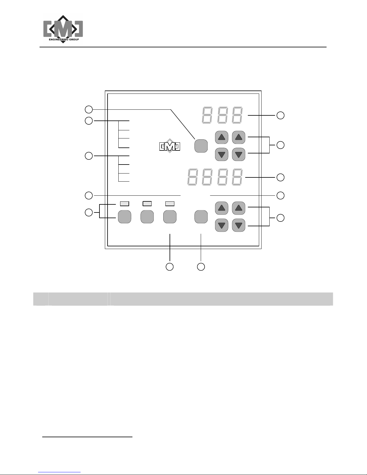
2. Description of the Keypad and Indicators
NDUSTRIAL ELECTRONICS
CMC I
12
11
10
OL
IDL
POS
FLT
MOV
OPN
CLS
EMP
SCAN
1
2
3
9
8
OPEN CLOSE CLEAR SET
PV
SV
A
CTUATOR INTERFACE
67
4
5
Figure 1 - Keypad and Indicators
ID Label Description of Operation
1 Upper Display Displays the name of the selected actuator.
2 Upper UP / DOWN Selects which actuator to view.
3 Lower Display Displays the process value or setpoint of the selected actuator.
4
Setpoint Value
Displaying the actuator setpoint
5 Lower UP /DOWN First press displays the setpoint of the selected actuator and each
subsequent press increases or decreases the setpoint value.
6 Set key
Saves the displayed setpoint only when SV is illuminated
Distributive Intelligence
CMC INDUSTRIAL ELECTRONICS LTD
Page 8

mAI085-MB Actuator Interface Technical Manual /4
ID Label Description of Operation
7 Clear key and
lamp
8 Open / Close keys
and indicators
9
Process Value
10 Status Indicators
11 Fault Indicators
Clears all actuator setpoints. First press illuminates the lamp, the second
press clears the setpoints and turns off the lamp. The lamp will turn off
automatically after 10 seconds if the key is not pressed the second time
and the setpoints will not be cleared.
If the CLEAR lamp is illuminated continuously and the operator keyboard
does not function, the keyboard has been locked by the Modbus
interface. Pressing and holding the CLEAR key for 10 seconds will
unlock the keyboard. The CLEAR lamp will extinguish when the
keyboard is unlocked. The setpoints will not be cleared during this
operation.
Opens or closes the actuators to their pre-set values. The indicators
display which mode is active.
Displaying the actuator position
MOV - actuator is currently moving to setpoint
OPN – if configured, indicates the actuator is fully open
CLS - if configured, indicates the actuator is fully closed
EMP - if configured, indicates the bin served by the actuator is empty
OL – if configured, the actuator has faulted due to excess running current
IDL - if configured, the actuator has faulted due to excess idle current
POS – the actuator failed to reach the selected position
FLT – the actuator controller is not communicating or has a hardware
fault
12 Scan key Press once to scan through all controllers at 1 second intervals. Press
the SCAN key again to cancel scanning. Pressing the up or down
actuator selection keys also cancels scanning.
Table 1 - Description of Keys and Indicators
Distributive Intelligence
CMC INDUSTRIAL ELECTRONICS LTD
Page 9
3. External Connections
mAI085-MB Actuator Interface Technical Manual /5
1 2 3 4 9
13
V- V+SHD_L D_H
12
V- V+G
7 8
65
10
11
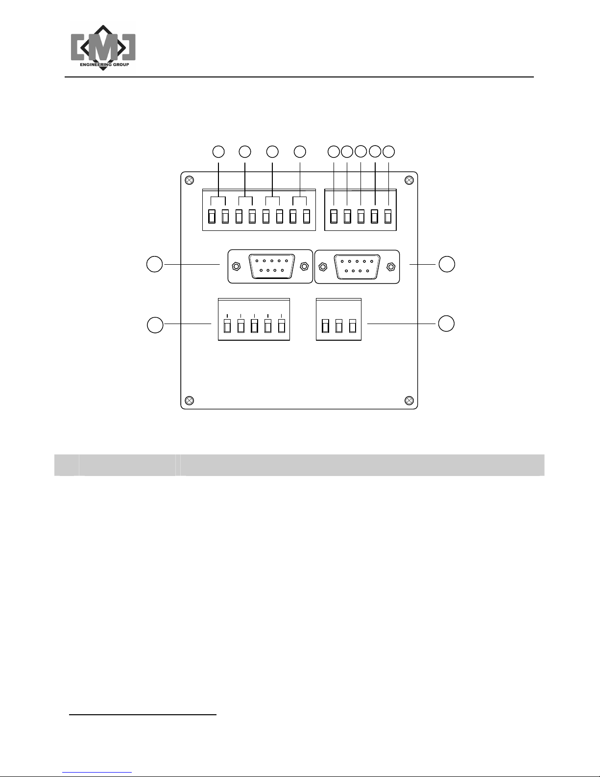
Figure 2 - Terminal Blocks and Connectors
ID Label Description
1 Output 1 Contact will close if in open mode or to start the conveying system.
Maximum load 1A @24VDC, 0.5A@120VAC
2 Output 2 Contact will close if in close mode or to stop the conveying system.
Maximum load 1A @24VDC, 0.5A@120VAC
3 Output 3 Contact will close if all setpoints are at zero.
Maximum load 1A @24VDC, 0.5A@120VAC
4 Output 4 Contact will close if the interface has an internal fault.
Maximum load 1A @24VDC, 0.5A@120VAC
5 Inputs 1 Energizing will select open mode.
6 Inputs 2 Energizing will select close mode.
7 Inputs 3 Energizing will clear all setpoints to zero.
8 Inputs 4 Energizing will force all actuators closed without affecting open/close
mode selection. Blending timers are ignored during a force close.
Distributive Intelligence
CMC INDUSTRIAL ELECTRONICS LTD
Page 10
mAI085-MB Actuator Interface Technical Manual /6
ID Label Description
9 Input Common Common connection for inputs. Inputs accept 8-32VDC of either polarity,
maximum load is 20mA.
10 Modbus Port Modbus network port - see Appendix for connections details, wired DCE
11 Input Power
Terminal
12 Output Power and
Network
Connections
13 Controller Network
Expansion
Download /
Upload Port
V+
G
V-
V+
D_H
SH
D_L
V-
22 -26 VDC @ 2.0A
Earth Ground
VDC Common
24 VDC fused at 1.75A
Data + (non inverted)
Shield
Data - (inverted)
VDC Common
RS232 connection for repeaters or fiber-optic cable drivers for the
controller network. Operates in parallel with the RS-485 port.
Port for exporting parameters to a comma delimited file - see Appendix B
for port wiring details, wired DTE
Table 2 - Description of Terminals and Connections
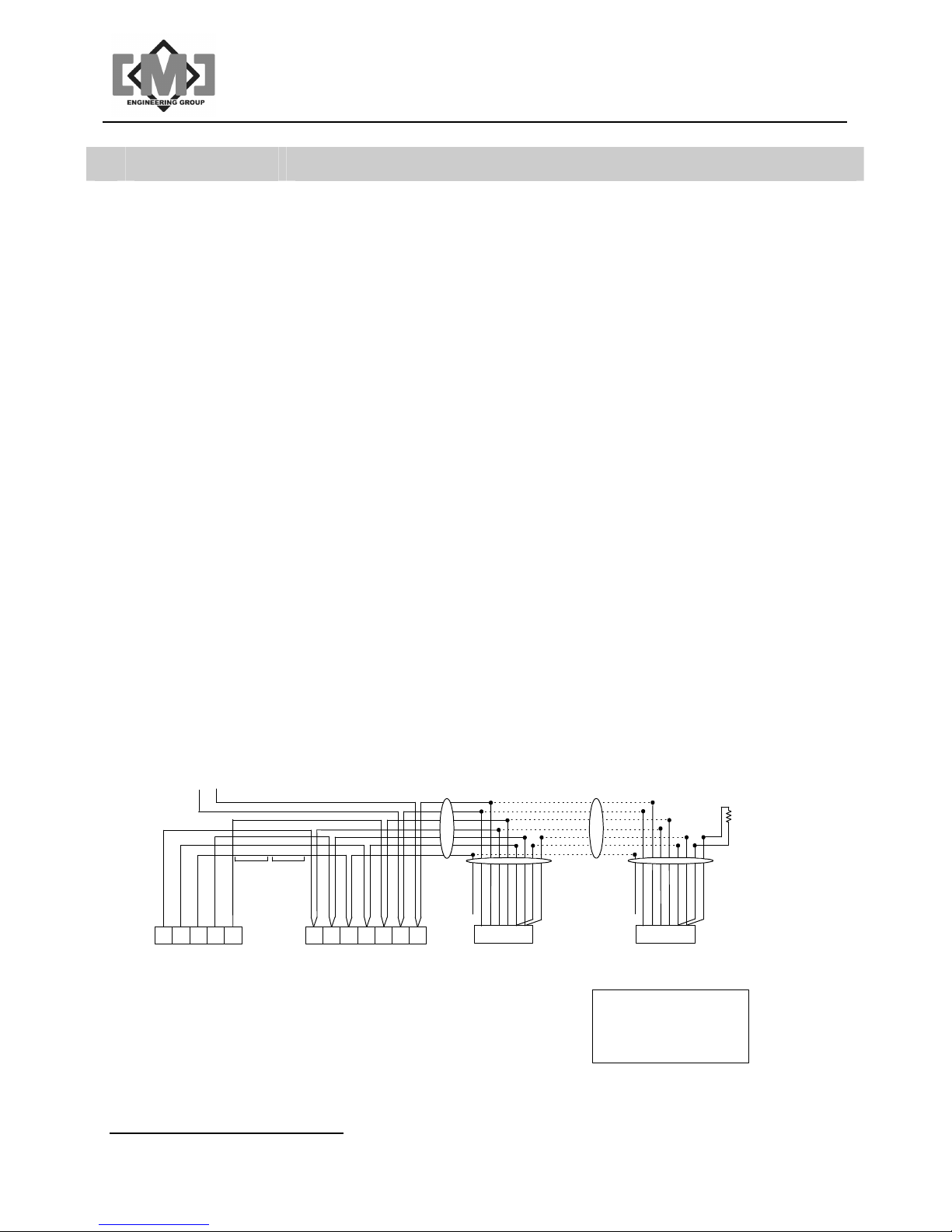
3.1 Power and Communications
A 2 or 3 pair shielded power and communication cable is utilized. Low capacitance twisted pair
cable is recommended. The cable should be sized to ensure voltage drop on the power
conductor does not exceed actuator controller input voltage specifications. The mAI085-MB
can accommodate up to a maximum of 31 actuator controllers. See drawing 10284 in the
Appendix for complete cabling details.
To force close
dry contact if used
GREEN
BLACK
RED
RED
BLACK
BLACK
WHITE
WHITE
BLACK
GREEN
SHIELD
SHIELD
2 Pair
3 Pair
Cables
Cables
WHT/BLU
SHIELD
WHT/ORG
ORG/WHT
24
5
DC Common
4321
Data -
Shield
Data +
24VDC Output
DC Common
D+SD-C
Data -
Shield
Data +
P1C
24VDC
Common
Input P1
X
mGP145-MB
Gate Positioner
BLU/WHT
WHT/BRN
BRN/WHT
WHT/GRN
GRN/WHT
654321
J2
SHIELD
WHT/ORG
X
mGP145-MB
Gate Positioner
WHT/BLU
WHT/BRN
BRN/WHT
WHT/GRN
ORG/WHT
GRN/WHT
654321
120 Ohm 1/
4W
Terminating
Resistor
BLU/WHT
J2
mAI085-MB
Actuator Interface
Figure 3 - Recommended Network and Power Connections
Distributive Intelligence
mAC185-MB
Actuator Controller
Data Cable
Pairs 20ga 22ga
2 9402 8723
3 9973 8777
Belden or equiv.
CMC INDUSTRIAL ELECTRONICS LTD
Page 11
mAI085-MB Actuator Interface Technical Manual /7
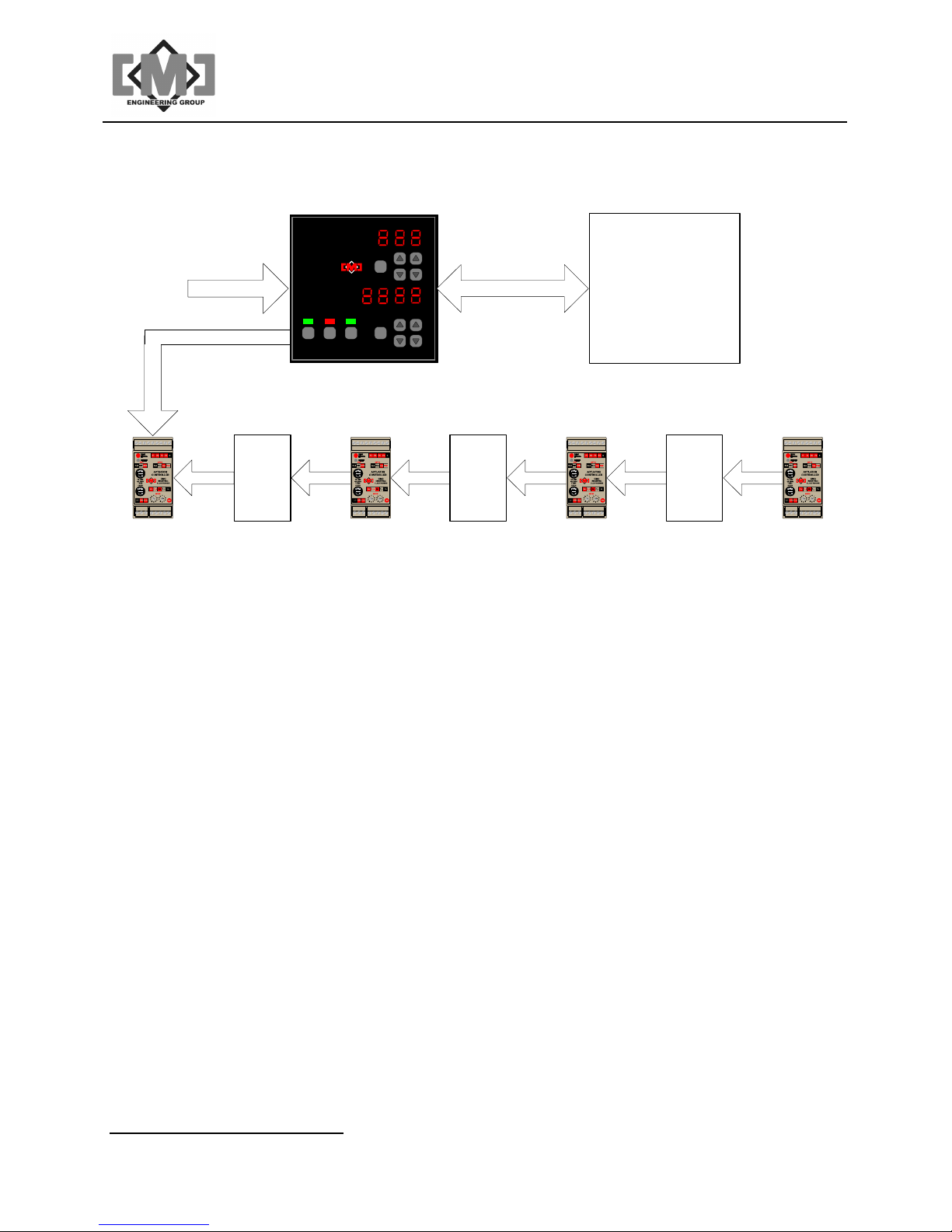
3.2 Optional Extended Data Network
CMC INDUSTRIAL ELECTRONICS
OL
IDL
POS
FLT
24VDC
1.25A
4 conductor
communications
cable RS-485
MOV
OPN
CLS
EMP
OPEN CLOSE CLEAR SET
PV
SCAN
SV
ACTUATOR INTERFACE
Modbus RTU
Host Computer
or PLC
RS-232
RS-485
repeater
Phoenix
Contact
2744429
Controller
91 - 100
Controller
1 - 30
RS-485
repeater
Phoenix
Contact
2744429
Controller
31-60
RS-485
repeater
Phoenix
Contact
2744429
Controller
61 - 90
Figure 4 - Extended Data Network
The interface can accommodate up to 100 actuator controllers if RS485 repeaters are used. A
typical repeater is the Phoenix Contact Part No. 2744429 optical isolated repeater. Up to 30
controllers can be on a single network segment (31 for the end of line). Using repeaters, a
linear network as shown above, or various forms of star or tee networks can be deployed as
required. The start of a branch on either a star or tee network must always begin with a
repeater.
A network expansion RS232 port is also provided. This port can connect directly to repeaters or
fiber-optic cable drivers. Controllers can be connected to both the standard RS485 port and the
expansion RS232 port. The port is designated J1 and is a female DB9 connector. It is wired
DTE.
Distributive Intelligence
CMC INDUSTRIAL ELECTRONICS LTD
Page 12

mAI085-MB Actuator Interface Technical Manual /8
This page intentionally left blank
Distributive Intelligence
CMC INDUSTRIAL ELECTRONICS LTD
Page 13

mAI085-MB Actuator Interface Technical Manual /9
4. Using the Interface
The controller has an easy to use keyboard for selecting and controlling the connected
actuators.
4.1 Selecting an Actuator Controller
Use the upper up or down keys to select the actuator. The right keys move between the
actuator one at a time. The left keys skip actuators at a time. The upper display indicates
which actuator is selected. The SCAN key allows the viewing of all connected actuators at one
second intervals. Pressing the SCAN key or any of the upper up/down keys can cancel scan.
4.2 Changing a Setpoint
The lower up/down keys change the setpoint for the selected actuator. The first press of any of
the up or down keys switches the lower display to the setpoint mode and the SV lamp will
illuminate. The right keys change the setpoint by 1. The left keys change the setpoint by 10.
The setpoint will not be saved and sent to the actuator until the SET key is pressed. If the SET
key is not pressed within 10 seconds, the display reverts to PV mode and the new setpoint is
discarded.
…Caution…
If it is required that all the actuators respond simultaneously to the
new setpoints, then first insure that the interface is in close mode
before making any changes to the setpoints.
The command to move the actuator is only sent when a setpoint has changed or the operating
mode is changed from closed to open. Pressing the SET key with the same setpoint value as
the previous move will not start a move operation.
4.3 Opening the Actuators
Pressing the OPEN key opens all actuators with a setpoint above 0. The OPEN indicator light
will illuminate. The STATUS display will indicate the status of the current open operation for the
selected actuator.
4.4 Closing the Actuators
Pressing the CLOSE key closes all actuators to a setpoint of 0. The CLOSE indicator light will
illuminate. The STATUS display will indicate the status of the current close operation for the
selected actuator.
Distributive Intelligence
CMC INDUSTRIAL ELECTRONICS LTD
Page 14

mAI085-MB Actuator Interface Technical Manual /10
4.5 Clearing the Setpoints
The CLEAR key allows the clearing of all actuator setpoints. The first press of the CLEAR key
illuminates the CLEAR lamp. The second press of the key clears all actuator setpoints to 0. If
the key in not pressed a second time within 10 seconds, the lamp will extinguish and the
setpoints will not
Distributive Intelligence
CMC INDUSTRIAL ELECTRONICS LTD
Page 15

mAI085-MB Actuator Interface Technical Manual /11
5. Configuration
The mAI085-MB Actuator Interface is configured using a menu driven interface. The operator
keyboard changes function during configuration. This section will describe the configuration of
the interface. The description will first define the keyboard functions, then describe the
configuration menus used.
5.1 Overview of System Configuration
Each actuator connected to the Interface has parameters that control its operation. These
parameters are stored in non-volatile memory at each actuator. These parameters can be
modified using the keyboard of the Interface. The Interface can also store in its internal nonvolatile memory, a copy of the parameters from each actuator.
The following table defines the steps used to set the actuator parameters and calibrate each
actuator controller.
Step Function Action at Interface Action at
Actuator Controller
1 Load Factory Default Values for the
Interface using the Factory Values
Menu..
2
Using the Controller Menu, set the iD
and adjust the parameters as required
for controller 1.
3
Using the Controller Menu, Snd the
adjusted parameters to controller 1.
4
From the Controller Menu, calibrate
controller 1, using the CAL function.
5 Test the configuration by exercising
controller 1
All internal Interface
no action
parameters are
overwritten with the
factory default values
Parameters for
no action
actuator controller 1
are adjusted in the
Interface parameter
table
no action Parameters at
actuator controller 1
are overwritten with
values from the
Interface
no action Calibration
parameters are
adjusted by the
actuator controller
Open and close the
gate to several
Controller will position
the gate
positions including fully
open and fully closed
and verify the limit
switch operation if
used
Distributive Intelligence
CMC INDUSTRIAL ELECTRONICS LTD
Page 16

mAI085-MB Actuator Interface Technical Manual /12
Step Function Action at Interface Action at
Actuator Controller
6
From the Controller Menu, use the
GEt function to upload the calibrated
parameters from controller 1.
7
From the Controller Menu, use the tPL
function to set the values from controller
1 as a template
6
Using the Factory Values Menu,
propagate the parameters from
controller 1 to the remaining controllers
within the Interface.
7
From the Main Menu, save the values
using the SAv command. Performing
the SAv now insures that the Interface’s
parameter table will not be lost should
power need to be cycled during the
remaining steps. You may perform a
SAv at any time during system setup.
Parameters for
controller 1 in the
Interface parameter
table are overwritten
with values from the
actuator controller
Parameters for
controller 1 in the
Interface parameter
table are stored in a
temporary template
register
Parameters for
actuator controllers 1100 in the Interface’s
parameter table are
overwritten with the
values from the
template
Parameters are saved
to non-volatile memory
in the Interface
no action
no action
no action
no action
8
From the Main Menu, use the Fnd
function to locate the remaining
controllers on the network. Exit
calibration mode and confirm that all of
the installed actuator controllers are
present on the network. If installed
controllers are not present, check field
address settings and wiring and Fnd
again until all of the controllers are
found.
Distributive Intelligence
All active flags are
cleared, then set for
those actuator
controllers located on
the network; controller
1 is always set to
active
CMC INDUSTRIAL ELECTRONICS LTD
no action
Page 17

mAI085-MB Actuator Interface Technical Manual /13
Step Function Action at Interface Action at
Actuator Controller
9
10.
11
12
13
From the Main Menu perform a Snd
function to send the previously saved
parameters to the remaining controllers.
From the Controller Menu, set the iD
for each of the remaining controllers.
Using the Controller Menu, Calibrate
each of the remaining controllers using
the CAL function.
From the Main Menu perform a GEt
function to retrieve the calibrated
parameters from all of the connected
actuator controllers.
From the Main Menu, save the
parameters using the SAv command
no action Parameters for all
active actuator
controllers on the
network are
overwritten with
values from the
Interface
ID parameter is
no action
overwritten for each
actuator
no action Calibration
parameters are
adjusted by the
actuator controller
Interface parameters
no action
are overwritten with the
values from all active
actuator controllers
Parameters are saved
no action
to non-volatile memory
Once you have completed this sequence, all of the actuator controllers will be calibrated and
their parameters saved in the Interface’s non-volatile memory. This allows an actuator
controller to be replaced and reconfigured with the parameter values saved in the Interface by
using the Snd command from the Controller Menu.
Distributive Intelligence
CMC INDUSTRIAL ELECTRONICS LTD
Page 18
mAI085-MB Actuator Interface Technical Manual /14
5.2 Configuration Keyboard Functions
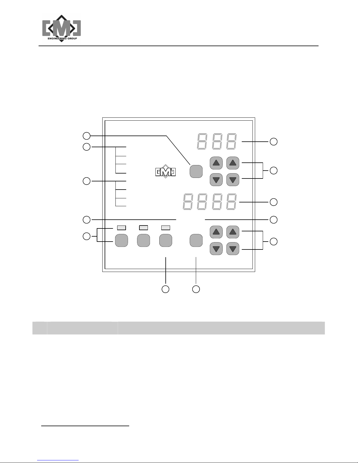
To enter configuration mode, press and hold the SCAN key for 10 seconds. The upper display
will show LoC, indicating entry into configuration mode.
NDUSTRIAL ELECTRONICS
CMC I
12
11
10
OL
IDL
POS
FLT
MOV
OPN
CLS
EMP
SCAN
1
2
3
9
8
OPEN CLOSE CLEAR SET
PV
SV
A
CTUATOR INTERFACE
67
4
5
Figure 5 - Configuration Keypad and Indicators
ID Label Description of Operation
1 Upper Display Displays the configuration menu item.
2 Upper UP / DOWN Selects the configuration menu item.
3 Lower Display Displays the configuration value. The flashing cursor indicates which
digit is being acted on.
4
Setpoint Value
Not used, off.
5 Lower UP /DOWN
Distributive Intelligence
For YES/no menu items the right up arrow key is YES and the right
down arrow key is no.
CMC INDUSTRIAL ELECTRONICS LTD
Page 19

For value entries, there is a flashing cursor indicating which digit is
being advanced. The left up/down arrow keys move the cursor left and
right. The right up/down arrow keys increase and decrease the value.
6 Set key Not used.
7 Clear key and lamp Not used .
mAI085-MB Actuator Interface Technical Manual /15
8 Open / Close keys
Not used.
and indicators
9
Process Value
Not used, off.
10 Status Indicators Not used, all off.
11 Fault Indicators Not used, all off.
12 Scan key Press and hold for 10 seconds to enter configuration mode. Press to
return to last menu or from the main menu, to exit configuration mode.
5.3 Configuration Menus
There are four level of menus within the configuration system. The keyboard operation remains
the same for all of the menus. Menu items are selected using the upper right arrow keys. The
SCAN key is used to move back one level in the menu tree. To exit configuration the SCAN
key is pressed from the Main Menu.
There are 2 typical responses to a menu item. The first is a Yes/No response. The lower right
keys select YES (up arrow) and no (down arrow). The second is to modify the value displayed
by the menu item. The lower arrow keys serve 2 functions when modifying values. The left
arrow keys positions the flashing cursor to the digit to be modified. The right arrow keys
increase or decrease the value.
Any changes made to the selected items are immediate. The interface has non-volatile storage
for the system parameters. A modification to the parameters using the menus does not update
this non-volatile storage directly. Be sure to backup any changes using the SAv function from
the Main Menu before removing power from the interface. Each time power is cycled, the
interface restores the saved values from non-volatile memory. Any changes made will be lost if
power is cycled before a SAv operation has been completed.
Distributive Intelligence
CMC INDUSTRIAL ELECTRONICS LTD
Page 20

mAI085-MB Actuator Interface Technical Manual /16
5.3.1 Main Menu
The Main Menu allows the selection of several sub-menus and selection of the global
parameter functions. All Main Menu items require YES/no responses.
Display Function Response
LoC
CtL
bUs
FAC
SAv
rCL
Go to the local interface parameters menu.
Go to the configure actuator controllers menu.
Go to the configure ModBus RS232 interface menu.
Go to the reset factory values Menu
Save the current configuration to non-volatile storage. A YES response
will display SUrE in the lower display. A second YES response will save
all parameters to non-volatile storage. The lower display will indicate
the progress of the operation. When the operation is completed
successfully, the lower display will show donE. Should the operation
not complete successfully the lower display will show FAiL. If the
operation fails, repeat the save. Should repeated attempts to save the
parameters fail, the non-volatile storage is damaged and the unit should
be replaced.
Recall the last saved configuration from non-volatile storage. This
operation is done automatically during normal startup of the interface.
The last saved configuration can be recalled by answering YES to this
item. A YES response to the SUrE display will restore all interface
parameters from non-volatile storage.
***************************** WARNING ********************************
YES/no
YES/no
YES/no
YES/no
YES/no
YES/no
This function will overwrite the current Interface parameter table
with the last saved table. All current adjustments to the table will
be lost.
***************************************************************************.
Fnd
Find all active controllers on the network. A YES response displays
SUrE in the lower display. The second YES response starts the
operation. The upper display indicates the actuator controller address
and the lower display the result of the query. All 100 addresses are
queried (1-100). Each controller, if found, will display YES on the lower
display. Unused addresses will show no. Once complete, the lower
display shows DonE. The Active flag for each controller is set or
cleared during this operation. Each address is tried 5 times.
GEt
Gets the operational parameters from all actuator controllers marked
active. A YES response displays SUrE in the lower display. The
Distributive Intelligence
YES/no
YES/no
CMC INDUSTRIAL ELECTRONICS LTD
Page 21

mAI085-MB Actuator Interface Technical Manual /17
Display Function Response
second YES response starts the operation. The upper display indicates
the controller address and the lower display the result of the query. All
addresses marked active are queried. Once complete, the lower display
shows DonE. Should an active actuator controller not be found, the
lower display will show FAiL. Each active address is tried 5 times. If you
are uncertain that a controller’s parameters have been retreived, use the
GEt function within the “Configure Actuator Controllers Menu” to verify
the operation.
Snd
dnL
UPL
dGn
Send the operational parameters to all active controllers on the network.
A YES response displays SUrE in the lower display. The second YES
response starts the operation. The upper display indicates the controller
address and the lower display the result of the query. All addresses
marked active are queried. Once complete, the lower display shows
DonE. Should an active actuator controller not be found, the lower
display will show FAiL. Each address is tried 5 times. If you are
uncertain that a controller’s parameters have been sent, use the Snd
function within the “Configure Actuator Controllers” Menu to verify the
operation.
***************************** WARNING ********************************
This function will overwrite all of the actuator controllers locally
saved parameters. This may cause unpredictable results in these
field devices. Verify the parameters in the mAI085-MB are correct
before executing this function.
Download the sensor data table to a PC. See Appendix A – Editing
Sensor data tables on a PC.
Upload the sensor data table from a PC. See Appendix A – Editing
Sensor data tables on a PC.
Go to the Modbus Slave Interface Menu.
YES/no
YES/no
YES/no
Distributive Intelligence
CMC INDUSTRIAL ELECTRONICS LTD
Page 22

mAI085-MB Actuator Interface Technical Manual /18
5.3.2 Local Menu
The local menu allows the configuration of parameters specific to the mAI085-MB.
Display Function Response
oPn
oPL
CPL
oDL
CDL
Selects the Open/Close mode at startup. Selecting YES will start the
interface with the OPEN lamp on. Selecting no will start the interface
with the CLOSE lamp on. The default value is no.
Selects the open relay output pulse timing. See “Controlling
Conveying Systems” for details on output pulse timing. A value of 0
disables this function. The default value is 0.
Selects the close relay output pulse timing. See “Controlling
Conveying Systems” for details on output pulse timing. A value of 0
disables this function. The default value is 0.
Selects the open delay. This delay allows for a conveying system to
start before beginning to open any actuators. The delay starts when
the OPEN key is pressed. See “Controlling Conveying Systems” for
details. A value of 0 disables this function. The default value is 0.
Selects the close delay. This delay allows for a conveying system to
purge after closing all actuators. The delay starts when the last
actuator has been commanded to close. See “Controlling Conveying
Systems” for details. A value of 0 disables this function. The default
value is 0.
YES/no
0-255
seconds
0-255
seconds
0-255
seconds
0-255
seconds
SPd
Selects the baud rate for the controller communications network.
9600, 1920
Changing the baud rate without first setting the baud rates for all of
the field devices will result in lost communication to the field devices.
The default setting is 19200 baud.
5.3.3 Actuator Controller Menu
The Actuator Controller Menu allows the configuration of the field actuator controller. In
addition this menu allows the setup of internal parameters that affect the open/close timing
of the actuator controllers. Additional menu items allow the recall and saving of the
parameters from the field device on an individual controller basis.
Provision is made to create a template from a specific controller. This template can then be
used to preset any additional controllers. Using the template/copy system can help speed
up the configuration process.
Distributive Intelligence
CMC INDUSTRIAL ELECTRONICS LTD
Page 23

mAI085-MB Actuator Interface Technical Manual /19
9
Z
A menu selection allows the remote calibration of the field actuator controllers. This function
sets the field controller into calibration mode and alerts the operator when the calibration is
complete.
Before this menu can be entered, the specific controller to be configured must be selected.
When entering this menu the upper display will show C 0, indicating controller address 0.
Use the upper arrow keys to select the controller to be configured. Selecting YES with the
lower arrow keys enters the configuration menu for the controller shown in the upper display.
Display Function Response
ACt
id
SPt
odL
CdL
Controller is active and present on the network. This flag is set
automatically when the Fnd function is executed. The network can
be manually configured using this menu item. The default setting is
no, not on the network except for address 1, which is YES.
Selects the Identification shown in the upper display for this actuator
during normal operation. The numbers 0-9 and all 26 letters of the
alphabet are represented in the character table. Some character
renditions are compromises due to the nature of the 7 segment
display. In addition, the -,_ and blank characters are included. The
default setting starts with 1 for address 1.
Sets the default setpoint for this actuator on startup. Values from 0
to full scale are permitted.
Sets the open delay time for this controller. When set, this timer
delays the opening of the actuator. The delay starts after the open
delay specified in the Local Menu. This timer can be used to insure
accurate blending of materials occurs during conveying system
startup. A value of 0 disables this function. The default value is 0.
Sets the close delay time for this controller. When set, this timer
delays the closing of the actuator. The delay starts when the CLOSE
key is pressed. This timer can be used to insure accurate blending of
materials occurs during conveying system shutdown. A value of 0
disables this function. The default value is 0.
YES/no
0-
A-
- _ blank
0-FS
0-255
seconds
0-255
seconds
CpY
Copy the template values to this controller. The template can be
loaded from any selected controller using the tPL menu item.
Selecting YES copies the template values to this controller and the
menu display returns to Act. This function will not operate until a
template has been set.
tPL
Set the template using this controller. Selecting YES copies this
controllers parameters to the template. The menu display returns to
ACt.
Distributive Intelligence
YES/no
YES/no
CMC INDUSTRIAL ELECTRONICS LTD
Page 24

mAI085-MB Actuator Interface Technical Manual /20
Display Function Response
GEt
Snd
Get the operational parameters from this controller. A YES response
displays SUrE in the lower display. The second YES response starts
the operation. Once complete, the lower display shows DonE.
Should the controller not respond, the lower display will show FAiL..
***************************** WARNING ********************************
This function will overwrite the Interface’s saved copy of the
parameters. Verify the parameters in the actuator controllers
are correct before executing this function.
***************************************************************************
Send the operational parameters to this controller. A YES response
displays SUrE in the lower display. The second YES response starts
the operation. Once complete, the lower display shows DonE.
Should the controller not respond, the lower display will show FAiL.
***************************** WARNING ********************************
This function will overwrite the actuator controllers saved
parameters. This may cause unpredictable results in this field
device. Verify the parameters in the mAI085-MB are correct
before executing this function.
***************************************************************************
YES/no
YES/no
CAL
Place the actuator controller in calibrate mode. The actuator
controllers have an automated calibration function. This function sets
the primary operational parameters for the controller by exercising
the actuator. A YES response displays SUrE in the lower display.
The second YES response starts the operation. During the
calibration sequence, the lower display shows rUn. Pressing YES will
stop the calibration sequence. The lower display will show DonE
when the sequence ends. If a calibration does not complete the
lower display will show FAiL. It is recommended that the results of
the field calibration be uploaded to the mAI085-MB using the GEt
command. This will allow the verification of the controller parameters
using the parameter functions of this menu. In addition, by saving
the parameters in the interface, a replacement field device can be
easily reprogrammed to match the replaced device using the Snd
command.
***************************** WARNING *******************************
The field actuator will move during this operation. Be sure field
personnel are notified and that the device is safe to operate
before executing this command.
Distributive Intelligence
YES/no
CMC INDUSTRIAL ELECTRONICS LTD
Page 25

mAI085-MB Actuator Interface Technical Manual /21
Display Function Response
This function will modify the actuator controllers saved
parameters. Verify that the calibration sequence completed
successfully and that the actuator is operating properly before
placing the field device into service. Actuator controllers that do
not complete the calibration sequence revert automatically to
the pre-calibration parameter table saved in the actuator
controller.
***************************************************************************
OFt -
CSP
Allows the adjustment of the field parameters of the actuator
controllers. The descriptions of these parameters are listing in the
Technical Manual for the mAC/GP1X5-MB actuator controllers and
gate positioners. Refer to the mAC/GP1X5-MB Technical Manual for
further information.
See
mAC/GP1X5
-MB
Technical
Manual
5.3.4 Modbus Interface Menu
The Actuator Interface allow remote operation and monitoring over a Modbus network.
Modbus is an industry standard network protocol for connecting PLC and field devices. The
Actuator Controller is a Modbus Slave device and only utilizes the RTU protocol. See “Using
the Modbus Network Interface” for further information.
Display Function Response
Adr
SPd
Par
Selects the Modbus slave address. The default address is 1.
Sets the baud rate of the Modbus serial port. The default baud rate
is 9600 baud.
Selects whether parity is active on the serial port. The default is no
parity.
1-125
300,600,
1200,2400,
4800,9600,
1920
YES/no
Odd
Select the type of parity, even or odd. A YES response selects odd
parity, a no response selects even parity. The default is even parity if
parity has been enabled.
Prt
Port Reset Timer; should the Modbus port become disabled due to
electrical disturbance. This timer will automatically restart the
Modbus Slave port; the timer will reset the port at the entered interval
(in seconds) if no valid Modbus messages are received. A setting of
0 disables this function.
Distributive Intelligence
YES/no
0-255
CMC INDUSTRIAL ELECTRONICS LTD
Page 26

mAI085-MB Actuator Interface Technical Manual /22
5.3.5 Factory Values Menu
The Interface can be configured to a range of factory preset values. The menu items allow
the selection of the actuator controller model, speed of actuator operation and actuator
accuracy. When the save function from this menu is executed all of the controller ID’s will be
reset to A1 – A100 and all of the controllers except controller 1 will be made inactive.
If no selections are made for tyP, SPd or ACC then the values from controller 1 will be used
as defaults. If a SAv is executed without tyP, SPd or ACC being set, the settings for
controller 1 will be propagated to all of the remaining controllers, the controller ID’s will be
reset to A1 – A100 and all of the controllers except controller 1 will be made inactive.
There are two ways to execute a factory reload. The first is to utilize a preset factory table.
This table contains known working values for all of the parameters suitable for most
installations. To select the correct tables for the actuator controller you are using, first use
tyP, SPd and ACC to select the model of your controller, the running speed of the actuator
and the required position accuracy. The required configuration can then be saved using the
Sav function.
The second method of saving default values uses a template that can be preset with a
modified set of values based on an individual actuator controller. To use this function, first
setup and test an individual actuator controller. Once the operation of this controller has
been verified use the template function (tPL) in the controller menu (CtL) to load the
parameter template buffer. To save this template buffer to all of the remaining controllers, do
not select a type, speed or accuracy, instead proceed directly to Sav function. Once select
this function will save the template parameter values to the Interface’s parameter table for
all100 controllers.
Note these tables are not automatically sent to the actuator controllers. Use the global Snd
command to move the Interface’s parameter table to the active controllers.
Display Function Response
tyP
Selects the model of actuator controller connected to the interface
185,165
145,125, nonE
SPd
Sets the full stroke speed of the actuator in seconds. Use the first
10,30,60, none
value that is longer than your actuators full movement speed.
ACC
Select the position accuracy required.
SAv Selecting YES will load the selected values to all 100 controller
0-10
YES/no
parameter storage locations. Note that the new values are not
automatically downloaded to the networked actuator controllers.
Use the Snd command to send the parameters to the actuator
controllers.
***************************** WARNING *******************************
All existing values will be overwritten and are not recoverable
***************************************************************************
Distributive Intelligence
CMC INDUSTRIAL ELECTRONICS LTD
Page 27

mAI085-MB Actuator Interface Technical Manual /23
5.3.6 Diagnostics Menu
The mTI085 has a built in diagnostics system. This menu allows for the diagnosis of the
input ports, communications ports and keyboard. Test connectors are required to test the
communications port. Press the SETUP key to exit any of the diagnostic tests.
Display Function Response
io
tP1
tP2
kYb
Tests the supervisory inputs and outputs. Once selected, energizing
a supervisory input will close the corresponding supervisory output,
i.e. energizing input closes output 1.
Test communications port 1. A loopback test connector that connects
pins 2 to 3 and pins 7 to 8 is required. If the test returns a 1 or 2
response, the RTS/CTS signals are not functioning. If the response is
10 – 27 the unit is unable to send or receive characters.
Test communications port 2. A loopback test connector that connects
pins 2 to 3 and pins 7 to 8 is required. If the test returns a 1 or 2
response, the RTS/CTS signals are not functioning. If the response is
10 – 27 the unit is unable to send or receive characters.
Once selected, each press of a keyboard key will return a numeric
code. Pressing the SETUP key exits the test and does not display a
code.
rUn
Error
message,
GOOd or
bAd
Error
message,
GOOd or
bAd
n/a
Distributive Intelligence
CMC INDUSTRIAL ELECTRONICS LTD
Page 28

mAI085-MB Actuator Interface Technical Manual /24
This page intentionally left blank
Distributive Intelligence
CMC INDUSTRIAL ELECTRONICS LTD
Page 29

mAI085-MB Actuator Interface Technical Manual /25
6. The Input / Output System
The mAI085-MB Actuator Interface has 4 discrete inputs and 4 discrete outputs. Figure 2 and
Table 2 detail the physical connections to the discrete signals. Each of the signals is described
below:
Name Description
Input 1
Pin 1
Input 2
Pin 2
Input 3
Pin 3
Input 4
Pin 4
Output 1
Pins 1 & 2
Energizing this input will select Open mode and turn on the OPEN indicator on the
front panel. Only the positive edge of the input signal is recognized and the input
must be de-energized between operations. Once energized, this input does not
affect front panel operator function.
Energizing this input will select Close mode and turn on the CLOSE indicator on
the front panel. Only the positive edge of the input signal is recognized and the
input must be de-energized between operations. Once energized, this input does
not affect front panel operator function.
Energizing this input will clear all of the actuators setpoints. The clear will occur
immediately. Only the positive edge of the input signal is recognized and the input
must be de-energized between operations. Once energized, this input does not
affect front panel operator function.
Energizing this input forces all of the actuators closed immediately. The actuators
will remain closed regardless of the controller being in Open mode. Open/Close
mode is not affected by this input and the actuators will re-open when this input is
de-energized if the interface is in Open mode. Open/Close timers are ignored by
this input and the force close will override any timing function in progress.
This output can have 2 functions depending on the setting of the oPL timer. If the
oPL timer is set to 0, this output will energize whenever the interface is in Open
mode. The output remains energized until the mode is changed to Close. If a
value has been entered into the oPL timer, this output will energize for the length
of time set by the oPL time, each time the Open mode is selected. This form of
operation can be used as a start signal for a conveying system.
Output 2
Pins 3 & 4
This output can have several functions depending on the setting of the cPL and
cDL timers. If the cPL timer is set to 0, this output will energize whenever the
interface is in Close mode. The output remains energized until the mode is
changed to Open. If a value has been entered into the cPL timer, this output will
energize for the length of time set by the cPL time, each time the Close mode is
selected. This form of operation can be used as a stop signal for a conveying
system. The energizing of this output will be delayed if a value other than 0 is set
in the oDL timer. The oDL timer can be used to purge a conveying system after
all of the actuator gates have been closed using the Close mode.
Distributive Intelligence
CMC INDUSTRIAL ELECTRONICS LTD
Page 30

Name Description
mAI085-MB Actuator Interface Technical Manual /26
Output 3
Pins 5 & 6
Output 4
Pins 7 & 8
This output will be energized any time all of the actuator setpoints are 0. The
output de-energizes whenever a non-zero setpoint is entered into any of the
actuators.
This output is energized whenever an internal fault is detected in the mAI085-MB
Actuator Interface. Possible faults are invalid parameter table (checksum
verification failed during startup), corrupted firmware or damaged hardware.
***************************** WARNING ********************************************
Operation of the mAI085-MB Actuator Interface may be unpredictable when
this contact is energized.
*****************************************************************************************
Distributive Intelligence
CMC INDUSTRIAL ELECTRONICS LTD
Page 31

mAI085-MB Actuator Interface Technical Manual /27
7. Controlling Conveying Systems
The mAI085-MB Actuator Interface allows the direct control of simple conveying systems. The
interface has several timers that facilitate this control. These timers in conjunction with the
discrete output system control the conveying system. The following timers are used:
ID Description Menu
oPL
cPL
odL
cdL
odL
Provides a pulsed output from Output 1 to start a conveying system. If this
value is set to 0, Output 1 will remain on continuously whenever the OPEN
lamp is on. If a value is set in this timer the output will pulse on for the time
selected in seconds each time the OPEN lamp turns on.
Provides a pulsed output from Output 2 to stop a conveying system. If this
value is set to 0, Output 2 will remain on continuously whenever the CLOSE
lamp is on. If a value is set in this timer the output will pulse on for the time
selected in seconds each time the CLOSE lamp turns on. The operation of
the output will be delayed if a value is entered into the cdL timer.
Delays the opening of the actuators to allow the conveying system to fully
start. Output 1 will energize (or pulse if oPL is set) immediately upon the
OPEN lamp illuminating. The actuators will begin to open after this delay in
seconds. This timer starts immediately upon entering Open mode.
Delays the stopping of the conveying system until all of the gates are closed
and the system has been purged. This timer starts after the CLOSE lamp
illuminates and all of the gates have been issued close commands. Once
this timer expires, Output 2 will energize (or pulse if cPL is set).
This timer allows for the different location of each actuator along a conveying
system. Actuators near the start of the conveying system must open first,
with each successive actuator opening a short time latter. This ensures an
accurate blend of the material. Each actuator has a timer that delays the
opening after the primary delay odL has expired.
LoC
LoC
LoC
LoC
CtL
cdL
This timer allows for the different location of each actuator along a conveying
system. Actuators near the start of the conveying system must close first,
with each successive actuator closing a short time latter. This ensures an
accurate blend of the material. Each actuator has a timer that delays the
closing when the interface enters Close mode.
Distributive Intelligence
CtL
CMC INDUSTRIAL ELECTRONICS LTD
Page 32

mAI085-MB Actuator Interface Technical Manual /28
Figure 6 details a typical start/stop sequence for a conveying system.
Open lamp
Close Lamp
Output 1
Output 2
Actuator 1
Actuator 2
Acutator 3
Enters Open mode
oPL Timer expires
oDL Timer expires
Actuator 1 oDL Timer expires
Actuator 2 oDL Timer expires
Actuator 3 oDL Timer expires
Enters Closed mode
Actuator 1 cDL Timer expires
Actuator 2 cDL Timer expires
Actuator 3 cDL Timer expires
cDL Timer expires
cPL Timer expires
Figure 6 - Conveying System Timing Diagram
Distributive Intelligence
CMC INDUSTRIAL ELECTRONICS LTD
Page 33

mAI085-MB Actuator Interface Technical Manual /29
8. Using the Modbus Network Interface
The mAI085-MB incorporates a RTU Slave Mobus interface. This interface responds to only 3
Modbus slave commands. The commands are 3 - Read Holding Registers, 6 - Write One
Holding Register and 16 - Write Multiple Holding Registers. The Modbus protocol allows a
maximum of 125 Register Reads and 100 Register Writes in a single transaction. The following
tables provide the register assignments for the Modbus interface. The command register within
the interface mimics the operation of the front panel keys and discrete inputs.
8.1 The Modbus Serial Interface
The physical connection is by a RS-232 port. The unit has a DB9 female connector, wired as a
DCE device. A modem or pin to pin cable can be used to connect the unit to a standard DTE
port. The connector pin-out is:
Pin Function at DTE device
1 DCD - always +9VDC
2 TX - data from mAI085-MB
3 RX - data to the mAI085-MB
4 DTR - not used
5 Common
6 DSR - always +9VDC
7 RTS - not used
8 CTS - always +9VDC
9 RI - not used
The unit supports 8 bit, even, odd or no parity in RTU mode. A full range of baud rates from
300 -19200 are supported.
8.2 Register Assignments
8.2.1 Read Only Registers
Two registers are assigned to each addressed controller. The mAI085-MB can address up to
100 controllers, starting from address 1 to address 100. Each addressed controller
corresponds to the following register table:
Distributive Intelligence
CMC INDUSTRIAL ELECTRONICS LTD
Page 34

mAI085-MB Actuator Interface Technical Manual /30
Register Function
40002 Controller 1 Process value
40003 Controller 1 Status
40004 Controller 2 Process value
40005 Controller 2 Status
40006 Controller 3 Process value
40007 Controller 3 Status
~ ~
40200 Controller 100 Process value
40201 Controller 100 Status
The controller process value is a 12 bit unsigned integer. The process value will occupy bits 0 11 of the process value word. The factory set range of the process value will be from 0 - 100,
signifying 0 - 100%. The controller status word definition is as follows:
Bit Function
0 Input 1 (Force Close) , 1 = input lamp off
1 Input 2 (Closed Limit) , 1 = input lamp off
2 Input 3 (Open Limit) , 1 = input lamp off
3 Input 4 (not assigned), 1 = input lamp off
4 Seek in progress, 1 = seeking
5 Motor running, 1 = running
6 Motor direction, 1 = close
7 not used, always 0
8 Position fault, 1 = did not reach position
9 Over fault, always 0, not implement in mGP145
10 Idle Load fault, always 0 not implement in mGP145
11 Parameter fault, 1 = parameters corrupted
12 Firmware fault, 1 = controller failed
13 Bad command, 1 = last command invalid
14 Calibration mode, 1 = in calibration mode
15 Communications fault, 1 = no communications
Distributive Intelligence
CMC INDUSTRIAL ELECTRONICS LTD
Page 35

mAI085-MB Actuator Interface Technical Manual /31
8.2.2 Read-Write Registers
Each controller has one register for the setpoint value. The setpoint value will occupy bits 0 11 of the setpoint value word. The factory set range of the setpoint value will be from 0 - 100,
signifying 0 - 100%. Writing a setpoint to the setpoint register will cause the actuator controller
to immediately position the actuator. The value in the setpoint register must change to initiate a
move. If the actuator faulted in the last attempted move, a different setpoint value will have to
be written to force a new move. The actuator will only move if the interface OPEN indicator is
on. Open mode can be selected by pressing the OPEN key. The interface can be configured to
start in open mode from the local menu and open mode can be forced over the Modbus
communications system through the interface command register.
Register Function
40301 Controller 1 setpoint
40302 Controller 2 setpoint
40303 Controller 3 setpoint
~ ~
40400 Controller 100 setpoint
8.2.3 mAI085-MB Special Registers
In addition, two special registers have been assigned. These registers are for controlling the
mAI085-MB Actuator Interface. The function of these registers is as follows:
Register R or R/W Function
40001 R mAI085-MB status
40300 R/W mAI085-MB commands
The mAI085-MB status register bit assignments are:
Bit Function
0 mAI085-MB input 1, 0 = input open
1 mAI085-MB input 2, 0 = input open
2 mAI085-MB input 3, 0 = input open
3 mAI085-MB input 4, 0 = input open
4 mAI085-MB output 1, 0 = output off
5 mAI085-MB output 2, 0 = output off
6 mAI085-MB output 3, 0 = output off
Distributive Intelligence
CMC INDUSTRIAL ELECTRONICS LTD
Page 36

mAI085-MB Actuator Interface Technical Manual /32
7 mAI085-MB output 4, 0 = output off
8 in open mode, 1 = yes
9 setpoints all cleared, 1 = yes
10 local keyboard disabled, 1 = yes
11 always 0
12 RAM fault, 1 = yes
13 mAI085-MB parameter corruption, 1 = yes
14 mAI085-MB firmware fault, 1 = yes
15 mAI085-MB in calibration, 1 = yes
There are 4 command bits to control the interface. These command bits are active only on the
0 to 1 transition. The bit must be returned to 0 before the command will execute again. Each
of the bits acts independently. The mAI085-MB command register bit assignments are:
Bit Function
0 mAI085-MB to close mode, 1 = yes
1 mAI085-MB to open mode, 1 = yes
2 mAI085-MB, clear all setpoints, 1 = yes
3 mAI085-MB disable local keyboard, 1 = yes
4 mAI085-MB enable local keyboard, 1 = yes
5 not used, always write 0
6 not used, always write 0
7 not used, always write 0
8 not used, always write 0
9 not used, always write 0
10 not used, always write 0
11 not used, always write 0
12 not used, always write 0
13 not used, always write 0
14 not used, always write 0
15 not used, always write 0
Distributive Intelligence
CMC INDUSTRIAL ELECTRONICS LTD
Page 37

9. Specifications
Description Characteristic
mAI085-MB Actuator Interface Technical Manual /33
DC Supply
Voltage
Current
Supervisory Inputs
Voltage
Current
Supervisory Contacts
Voltage
Current
Actuator Controller DC Supply
Voltage
Current
Actuator Controller Communications
Standard
Distance
Input Load
Termination
Auxiliary Communications Ports
Modbus RTU Port
Download/Upload and
Controller Network Expansion port
20 - 28VDC
2.0 @ 24VDC
24VDC
20mA
32VDC, 120VAC
1.0A @ 24VDC, 0.5A @ 120VAC Resistive
20 - 28VDC
1.5A @ 24VDC
RS485 differential
500m (1640ft.)
12kΩ, standard
120Ω balanced line
RS-232C, DB9S connector, wired DCE
RS-232C, DB9P connector, wired DTE
Environment
Temperature
Relative Humidity
Dimensions
Height
Width
Depth
Distributive Intelligence
-40 to 70°C (-40 to 158°F)
0 to 95% non-condensing
90mm (3.55”)
90mm (3.55”)
127mm (5.0”)
CMC INDUSTRIAL ELECTRONICS LTD
Page 38

mAI085-MB Actuator Interface Technical Manual /34
This page intentionally left blank
Distributive Intelligence
CMC INDUSTRIAL ELECTRONICS LTD
Page 39
mAI085-MB Actuator Interface Technical Manual /35
10. Appendix 1 - Editing Controller Setup Tables on a PC
The mAI085 can download and upload the field actuator controller setup tables to a PC over a
standard serial port. Using software supplied as part of the Windows operating system and
spreadsheet software, such as Excel, the configuration tables can be conveniently edited and
sorted. The download (dnl) and upload (UPL) functions are accessed from the main menu.
See Section 5 – Setup for details on selecting these functions. Before starting these functions
you will need the following:
1. A PC running Windows software;
2. A null-modem serial cable with a 9 pin female connector on both ends;
3. A communication software package, such as HyperTerminal that is supplied with most
Windows OS distributions.
The following instructions assume you are using HyperTerminal for communications and Excel
for editing:
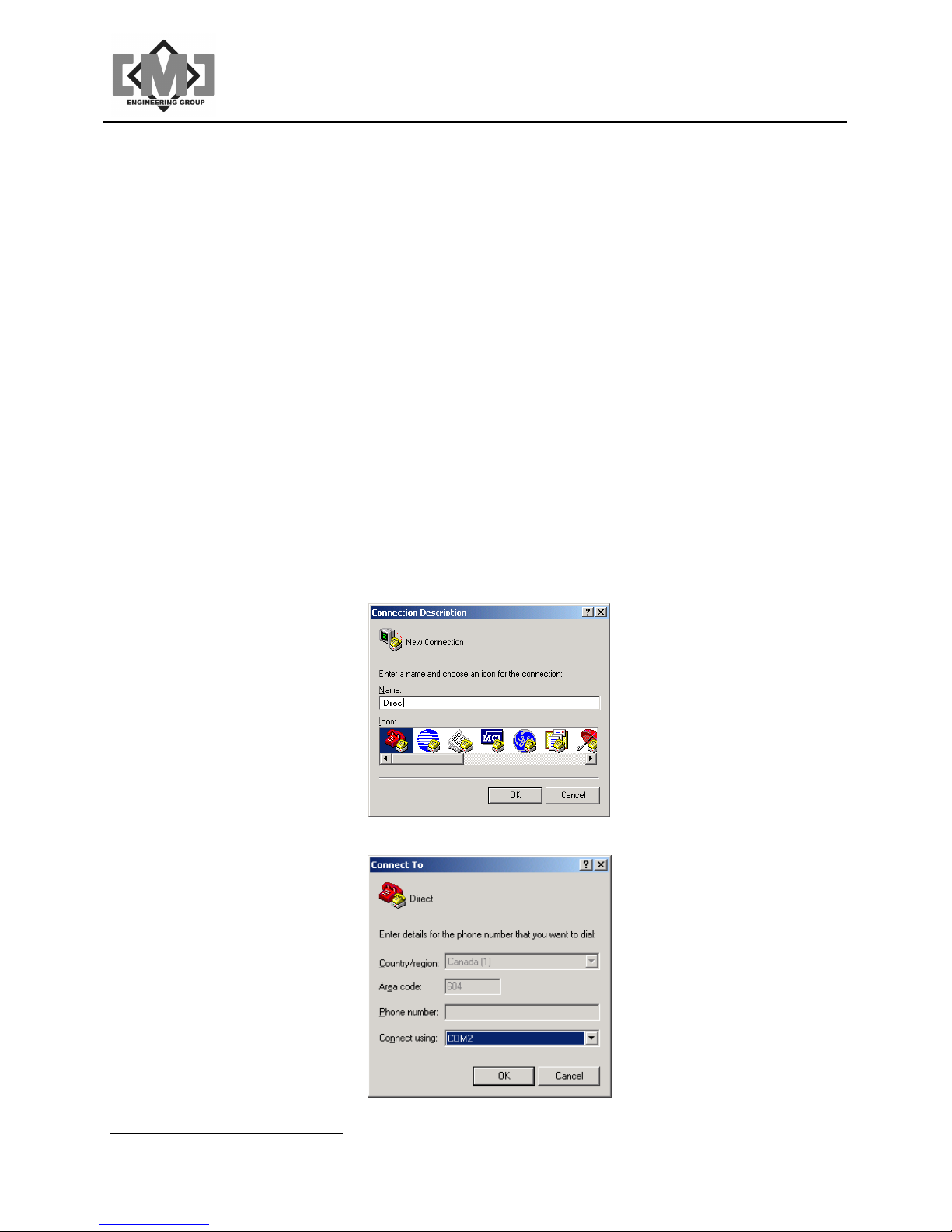
10.1 Setting up HyperTerminal
1. Open HyperTerminal;
2. Enter the name Direct for the connection name as below then click OK;
3. Select the communications port you are using and then click OK;
Distributive Intelligence
CMC INDUSTRIAL ELECTRONICS LTD
Page 40
mAI085-MB Actuator Interface Technical Manual /36
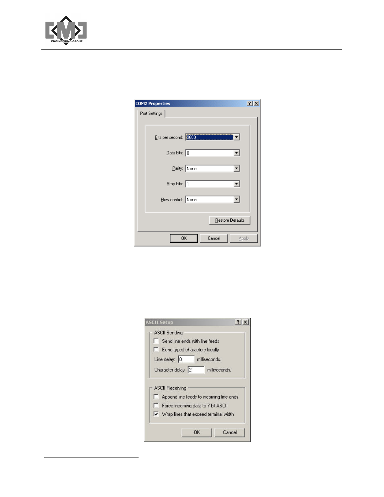
4. Set the communications port settings as shown and then click OK. The settings are
Bits per second - 9600, Data bits - 8, Parity - None, Stop bits -1, Flow control None;
5. On some computers it may be necessary to add a short delay to each transmitted
character when uploading configurations to the mTI085. From the File menu in
HyperTerminal, select Properties. On the next screen select the Settings tab. On the
next screen click the ASCII Setup button. Set the Character delay field to 2
milliseconds and then click OK;
Distributive Intelligence
CMC INDUSTRIAL ELECTRONICS LTD
Page 41
mAI085-MB Actuator Interface Technical Manual /37
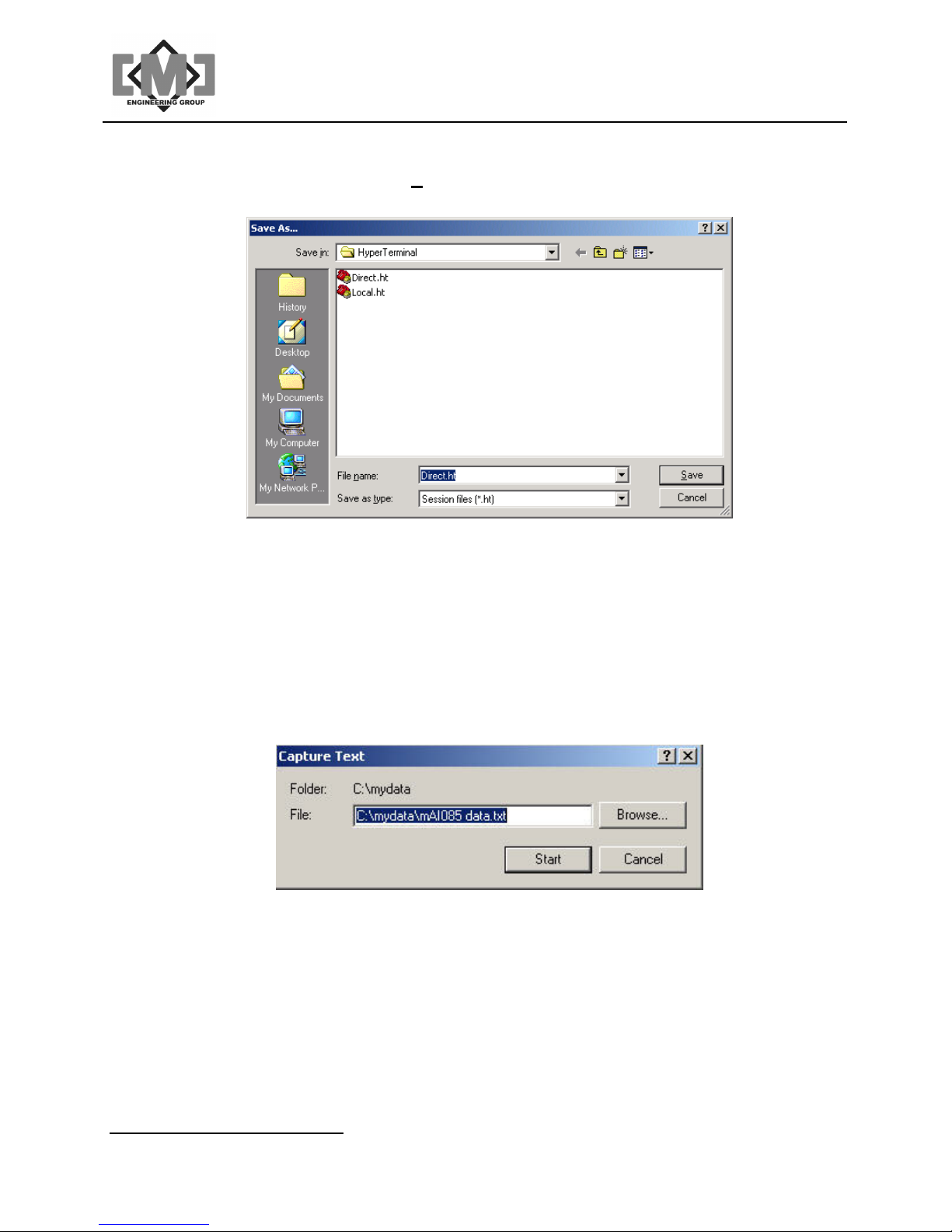
6. You will now be at the main HyperTerminal Screen. Select File and then Save and the
screen below will appear. Click Save to save this configuration as Direct.ht. You can
now open HyperTerminal from the Direct Icon anytime you require this connection.
You are now ready to download the configuration file.
10.2 Downloading the Configuration to the PC
1. Select dnL from the Main Menu;
2. From HyperTerminals menu, click on Transfer and then Capture Text. Enter the path
and file name where you want to store the configuration file as shown below. Note
HyperTerminal appends data to existing files. You must delete the file each time you do
a download or use a different file name. When you have completed entering the name,
click Start;
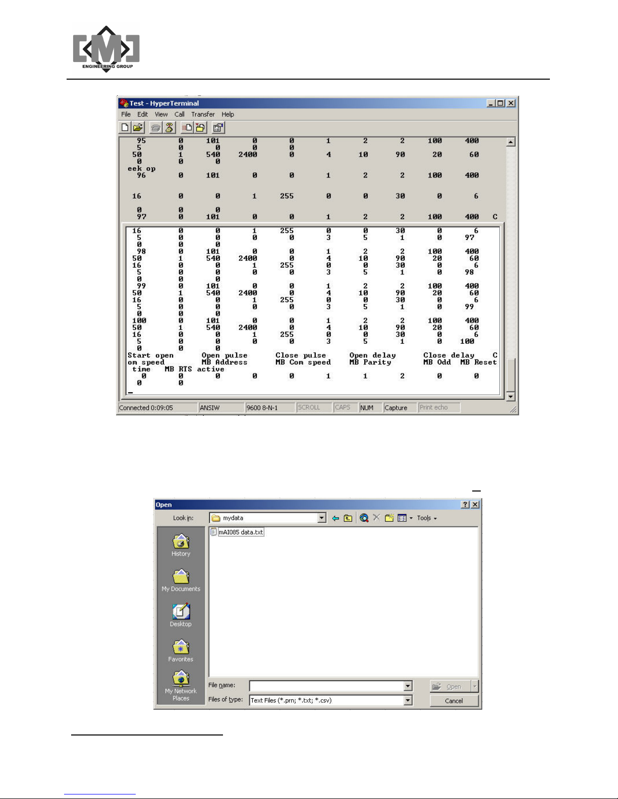
3. On the mTI085 press YES and the YES again to the SurE prompt. The mTI085 will
begin dumping the configuration file to HyperTerminal. When the transfer is complete,
the mAI085MB will show donE and your PC screen will appear as:
Distributive Intelligence
CMC INDUSTRIAL ELECTRONICS LTD
Page 42
mAI085-MB Actuator Interface Technical Manual /38
4. From the HyperTerminal menu, select Transfer and then Capture Text, then Stop. You
have now created a “.txt” file containing the configuration data.
5. Open Excel and select File and then Open. You will have to change the type of file to
open in the highlighted dialog box as shown below. You want to open files of type “.txt”.
Once you have selected file type “.txt”, select your data file and then click Open.
Distributive Intelligence
CMC INDUSTRIAL ELECTRONICS LTD
Page 43
mAI085-MB Actuator Interface Technical Manual /39
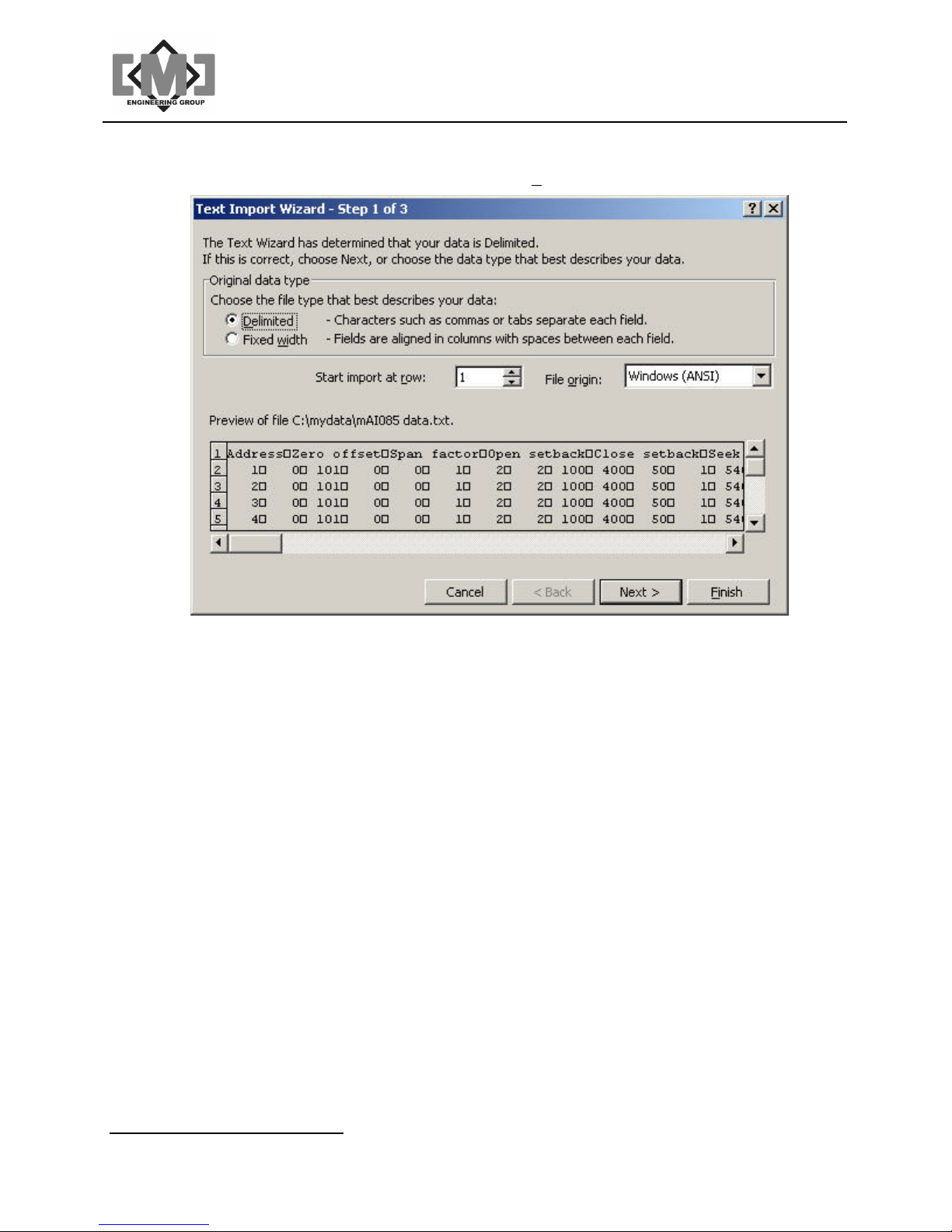
6. Excel will display a data import dialog. The data from the mAI085MB is pre-formatted to
be automatically imported into Excel. Just click Finish to import the data.
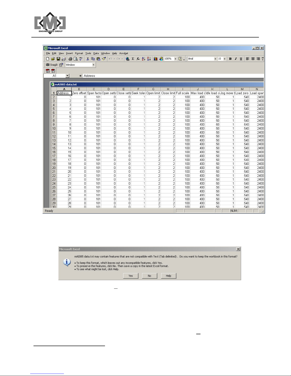
7. Adjust the width of the columns A so you can see the headings. Edit the data as
required. A sample of an Excel spreadsheet is shown below. The columns correspond
directly with the menu prompts from the CtL menu. There are 2 sections to the file. The
first is the controller setup parameters. The second is the setting saved under the LoC
menu. Do not modify the headings rows. These rows are discarded when uploaded to
the mAI085MB.
Note that the mAI085MB does not verify the entries you have made. Do not change the
format of the spreadsheet in anyway and do not enter field longer than the maximum
allowed lengths. Always download and upload the entire controller range. The
mAI085MB can be reset to factory values using the Fac option from the main menu.
Distributive Intelligence
CMC INDUSTRIAL ELECTRONICS LTD
Page 44
mAI085-MB Actuator Interface Technical Manual /40
8. When finished, save the file as a “.txt” file. Excel will prompt you to change the type of
file when you save or exit, as it defaults to the “.xls” file format. Always answer to not
change format of the file. The screen sample below shows a typical dialog.
Note you must click on Yes at this dialog to save your file as a “.txt” file.
10.3 Uploading the Configuration to the mAI085MB
1. To upload the file to the mTI085, select UPL from the main menu of the mAI085MB.
HyperTerminal should be open and the cable connected.
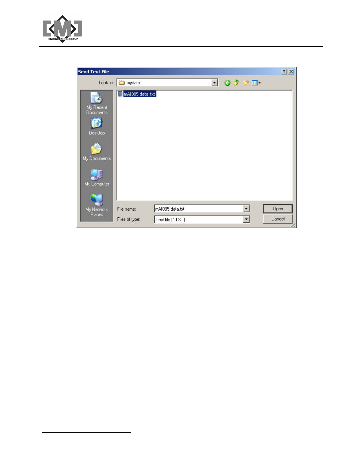
2. Select Transfer and then Send Text File from the HyperTerminal menu. Select the file
from the dialog box, but do not double click on the file, or click Open yet.
Distributive Intelligence
CMC INDUSTRIAL ELECTRONICS LTD
Page 45
mAI085-MB Actuator Interface Technical Manual /41
3. On the mTI085 select YES, and then YES again to the SurE prompt. The lower display
will show 128. Click on Open on the HyperTerminal dialog to start the transfer. The
lower display will count down as the sensor data is received.
4. When the transfer is complete. The lower display will show donE. Select Sav from the
Main menu of the mAI085MB to save your uploaded data.
Distributive Intelligence
CMC INDUSTRIAL ELECTRONICS LTD
Page 46

mAI085-MB Actuator Interface Technical Manual /42
This page intentionally left blank
Distributive Intelligence
CMC INDUSTRIAL ELECTRONICS LTD
Page 47

mAI085-MB Actuator Interface Technical Manual /43
11. Appendix 2 - Drawings
Drawings included in this appendix are:
Drawing Number Description
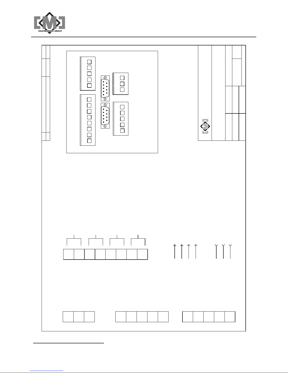
10283 mAI085-MB Connection details
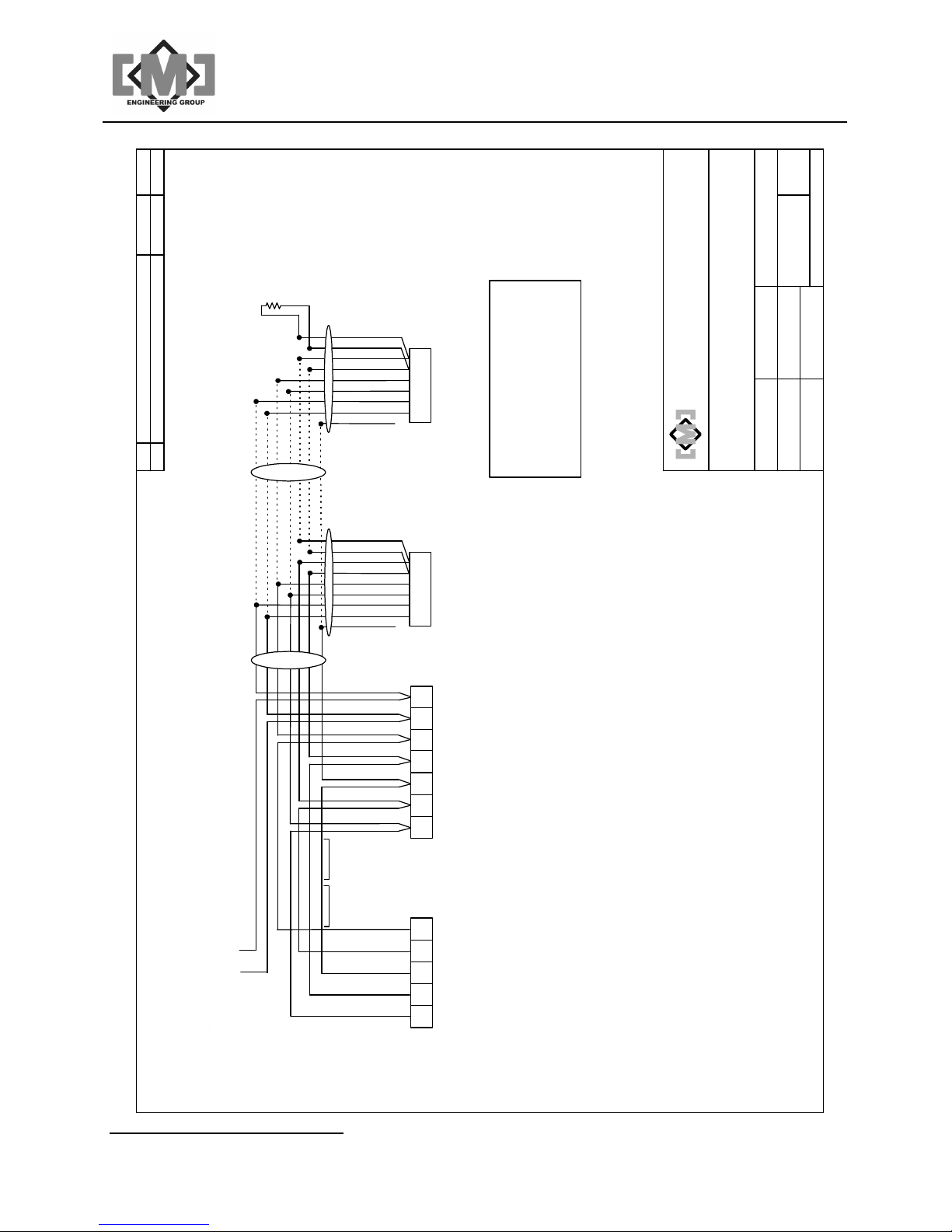
10284 Gate Positioner Data Cable Wiring Overview
Distributive Intelligence
CMC INDUSTRIAL ELECTRONICS LTD
Page 48
mAI085-MB Actuator Interface Technical Manual /44
A
J2
Modbus
TB3
Inputs
TB4
Outputs
A Change identifiers for com port J1 JULY 2/07 DMF
1
6
1 2 3 4 51 2 3 4
9
5
5
9
6 7 8
5
6
1
TB1
Power
1 2 3
5
1 2 3 4
Supply
Burnaby, BC Canada
CMC Industrial Electronics Ltd.
TB2
Data
mAI085MB Rear View
Network
REF:
D. FORST
DRAWN BY:
mAI085MB Connection Details
DO NOT SCALE
1 OF 1
10283
PAGE:
DRAWING NO: REV:
APPROVED BY:
CHECKED BY:
SEPT 23, 1999
COPYRIGHT 1999
DATE:
J1
Expansion
In Open
1
TB4 - Isolated Relay Outputs
TB1 - Power Supply
2
24VDC Common
Earth Ground
1
2
Distributive Intelligence
In Close
All Setpoints
Cleared
Fault
2 - RX Data In
3 - TX Data Out
5 - Data Common
7 - RTS Out
2 - TX Data Out
3 - RX Data In
5 - Data Common
and Download / Upload Port
3
4
5
6
7
8
24VDC, 2A Input
3
DC Common
Data -
Shield
1
2
TB2 - Data Network
3
J1 - Controller Network Expansion
Data +
24VDC Output
4
5
Set Open
1
TB3 - DC Control Inputs
J2 - Modbus Network
Set Close
Clear Setpoints
Force Closed
Input Common
2
3
4
5
CMC INDUSTRIAL ELECTRONICS LTD
Page 49
mAI085-MB Actuator Interface Technical Manual /45
Terminating
DC Common
mGP145-MB
mGP145-MB
Gate Positioner
DC Common
A
DATE APP.
4W
120 Ohm 1/
BLU/WHT
J2
WHT/BLU
DESCRIPTION
REMOVE mBA085 AND ADD mAC185-MB AUG 14/06 DMF
A
REV
GRN/WHT
WHT/GRN
BRN/WHT
WHT/BRN
ORG/WHT
WHT/ORG
SHIELD
9402 8723
9973 8777
Data Cable
Pairs 20ga 22ga
Belden or equiv.
Burnaby, BC Canada
CMC Industrial Electronics Ltd.
REF:
D. FORST
Wiring Overview
DRAWN BY:
Gate Positioner Data Cable
DO NOT SCALE
1 OF 1
10284
PAGE:
DRAWING NO: REV:
APPROVED BY:
CHECKED BY:
SEPT 23, 1999
COPYRIGHT 1999
DATE:
J2
SHIELD
Gate Positioner
RED
BLACK
BLACK
GREEN
RED
BLACK
dry contact if used
Distributive Intelligence
P1
Common
24VDC
24
Data +
D+D-
Shield
Data -
3 Pair
WHITE
WHITE
Cables
BLACK
SHIELD
2 Pair
Cables
GREEN
SHIELD
24VDC Output
mAC185-MB
Actuator Controller
Data +
Shield
Data -
mAI085-MB
Actuator Interface
permissive is used.
Notes:
1. Data Wiring 2 or 3 pair shielded cable, up to 32 gates per network segment.
3. Wire colors shown are for Belden multi-pair cabling.
2. Force all closed permissive is a programmable option. Use 3 pair data cable if
CMC INDUSTRIAL ELECTRONICS LTD
Page 50

mAI085-MB Actuator Interface Technical Manual /46
This page intentionally left blank
Distributive Intelligence
CMC INDUSTRIAL ELECTRONICS LTD
 Loading...