

Page 1
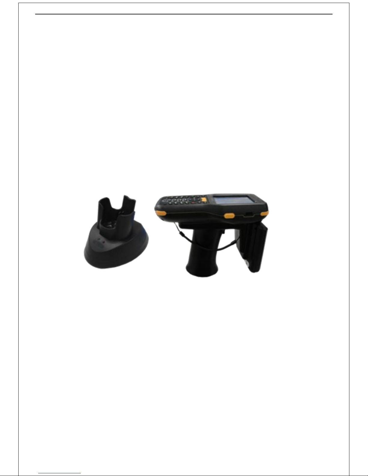
UHF RFID Handheld Reader
User Guide
Actions: Please read the corresponding chapters according to your selected modules.
Page 2
1
Part 1 Quick Guide
1.1 Products Overview
UHF RFID handheld scanner is based on WINCE 6.0 operating system .It supports ISO18000-6 c (EPC C1 G2) agreement, reading
range can reach up to 7 meters; Synchronous data can be exchanged through the USB interface with PC; Support 32G Micro SD
(T - Flash) card expansion; Resistant data security protection, data would not be lost under the condition of completely off
electricity.
Product Application:
Power logistics warehouse, assets, animal husbandry, books, tickets, entrance guard, container, etc.
Features:
Support EPC Class1 Gen2/ISO18000-6C;
Adjustable output power, range: 10dBm~28dBm, 1 DBM step;
Work range is longer than 7m (based on UPM SHORTDIPOLE_M3 tag);
3500mAh @ 7.4V battery for 4 hours normal operation or 20 days standby.
Ergonomic hand grip design, easy holding, less tired.
Specifications:
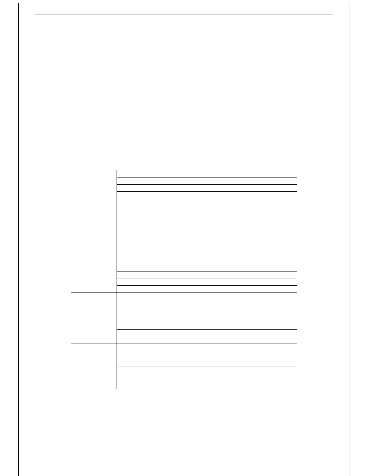
Specifications
CPU
ARM11, 667MHz
Memory
128MB SDRAM,256MB NAND-Flash
Operating System
Microsoft® Windows CE 6.0
Communication
WLAN 802.11b/g
Bluetooth 2.1(optional)
GPRS(optional)
Display
3.2’’ 240 x 320 TFT-LCD with resistor type touch
screen, backlight adjustable
Storage Card
4G MicroSD card, support up to 32G
Battery
Work time
4 hours normal operation
Barcode Scan
1-D module :Symbol SE955
2-D module :Honeywell 5180(optional)
Expansion Module
GPRS, GPS, 2.4G
Keyboard
27 buttons
Audio
1524 speaker
USB port
USB Slave
RFID
Protocol
EPC Class1 Gen (ISO18000-6C)
Working Frequency
CN:920MHz~925MHz
US:902MHz~928MHz(default)
EU:865MHz~868MHz
customized within 860MHz~960 MHz
Read Range
7M (related to tag)
Write Range
3M (related to tag)
Overview
Dimensions
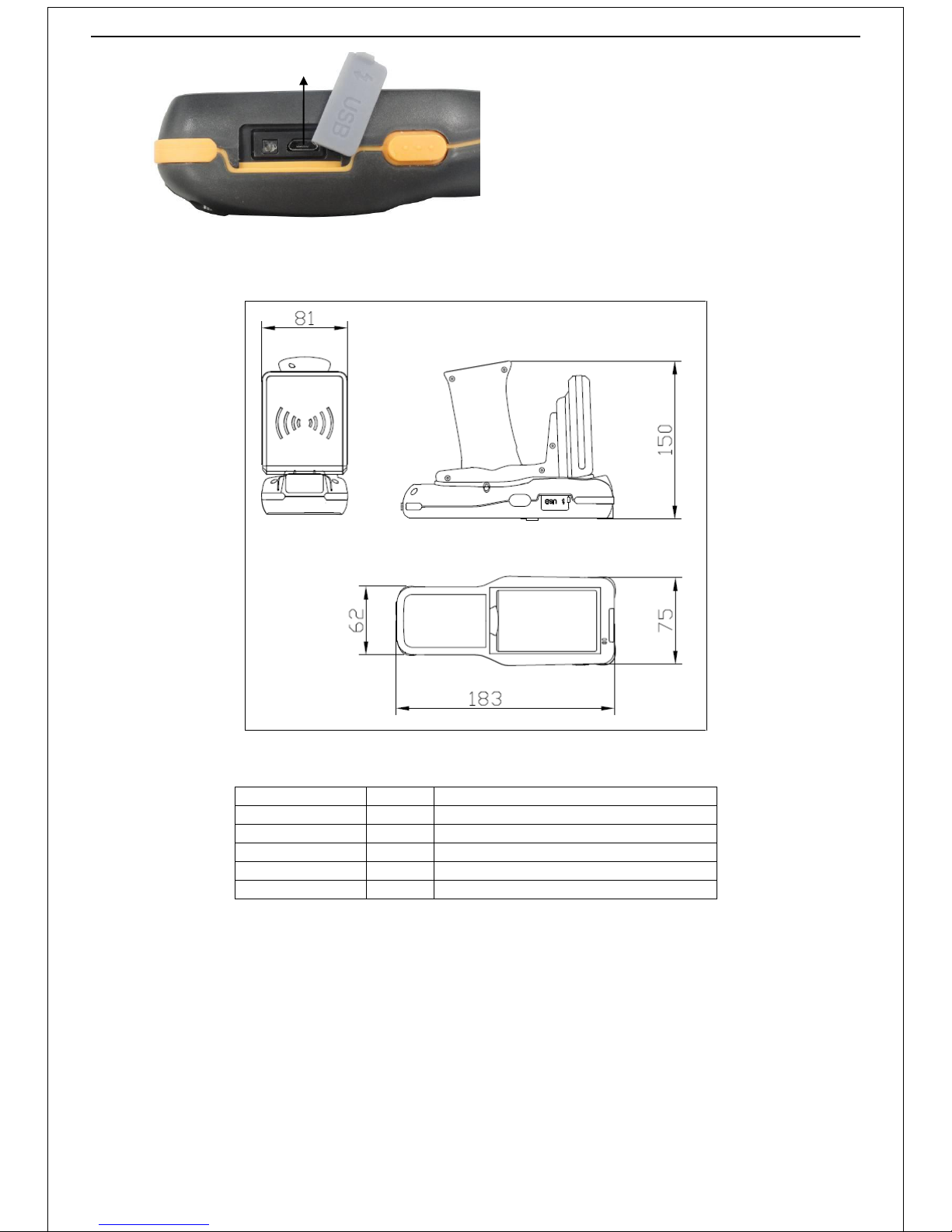
81*183*150mm
Weight
1.115kg(include charging dock)
Environment
Specifications
Operating temperature
-20℃~50℃
Storage temperature
-20℃~70℃
Storage humidity
5%~95% no condensation
Protection rating
IP65
Page 3
2
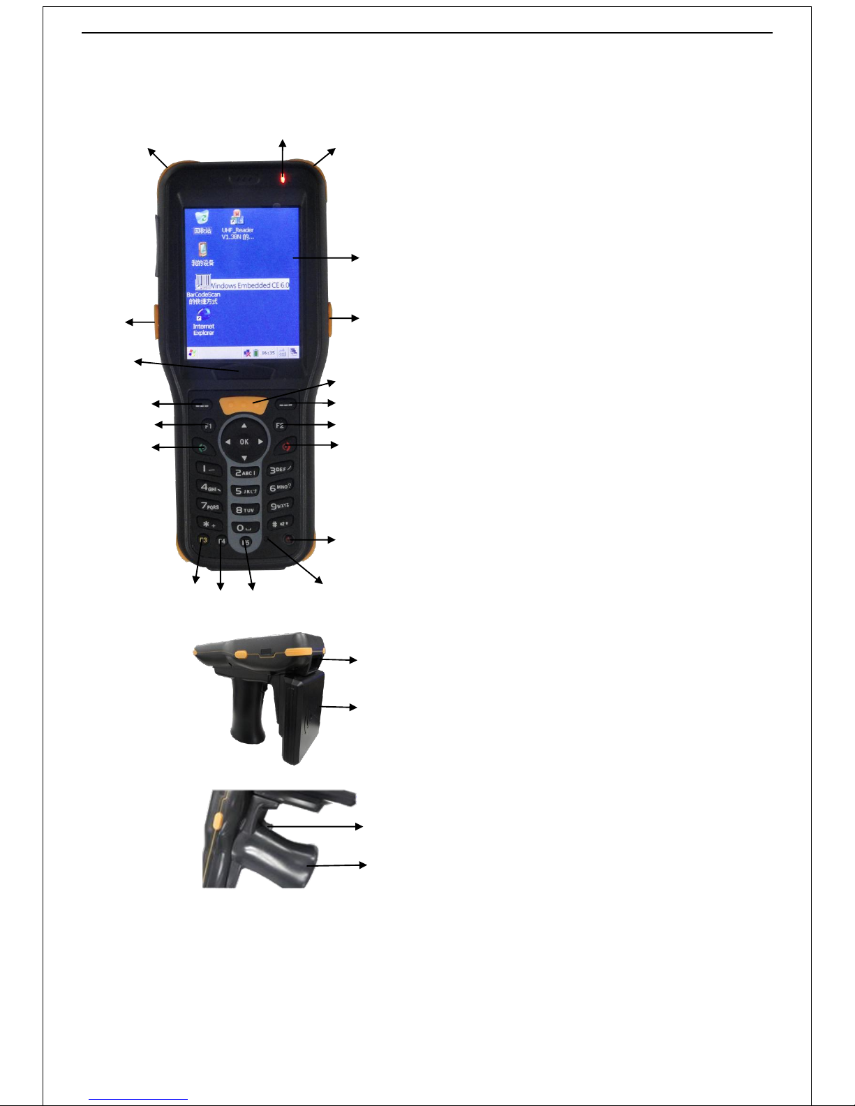
1.2 Graphic Description
Positive
Profile
16
16
16
1
16 3 4 5 6
7
8
9
10
11
15
12
14
13
2
Text Description:
1. Indicator lamp(power & network)
2. Touch screen
3. Function key
4. Enter key
5. Delete key
6. User-defined
7. Turn on/off button
8. Reset button
9. User-defined
10. User-defined
11. User-defined
12. User-defined
13. Switch input key
14. User-defined
15. Nameplate
16. Waterproof and silicone protective circle
1
2
Text Description:
1. Barcode scanning area
2. Reading area
1
2
Text Description:
1. Handle button
2. Battery embeded area
Page 4
3
1.3 Dimensions(Unit: mm):
1.4 Fittings
Name
Quantity
Remark
Host 1 UHF RFID handheld scanner
Touch screen pen 1 With spring rope
USB cable 1 USB to Micro 5pin
Charging base 1 /
Power adapter 1 12V/3A
1.5 Startup and Shutdown
1) Power on
Press the power button on the lower right corner of keypad until windows CE logo and time passing bar appear.
2) Power off
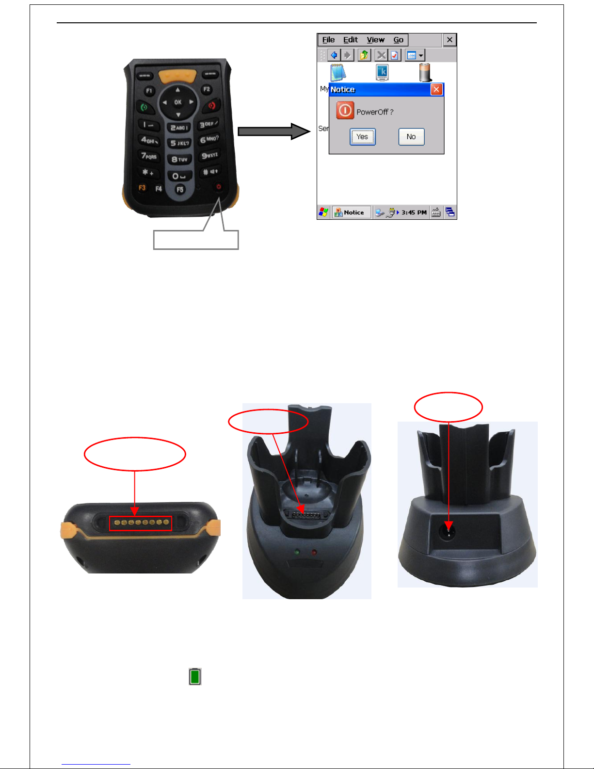
Press the power button until pops dialog box “Are you sure you want to turn off handheld” on screen, then click “yes” to
power off the system, as shown in the following diagram 1.1:
1
Text Description:
1. USB port
Page 5
4
Dialog box
Diagram 1.1
1.6 Charge battery
1) Steps
Press "charging chip contact" into the charging base (when "charging chip contact" is good contacted with the charging
base, charging base will bright red light for 10 seconds and then go out). Insert the power adapter into the power supply
interface of the charging base, plug the charge block to electricity supply.
After charging is completed, do first take the scanner out, and then disconnect the power supply of charging base. As shown in
diagram 1.2:
Diagram 1.2
2)Check the charging status and battery
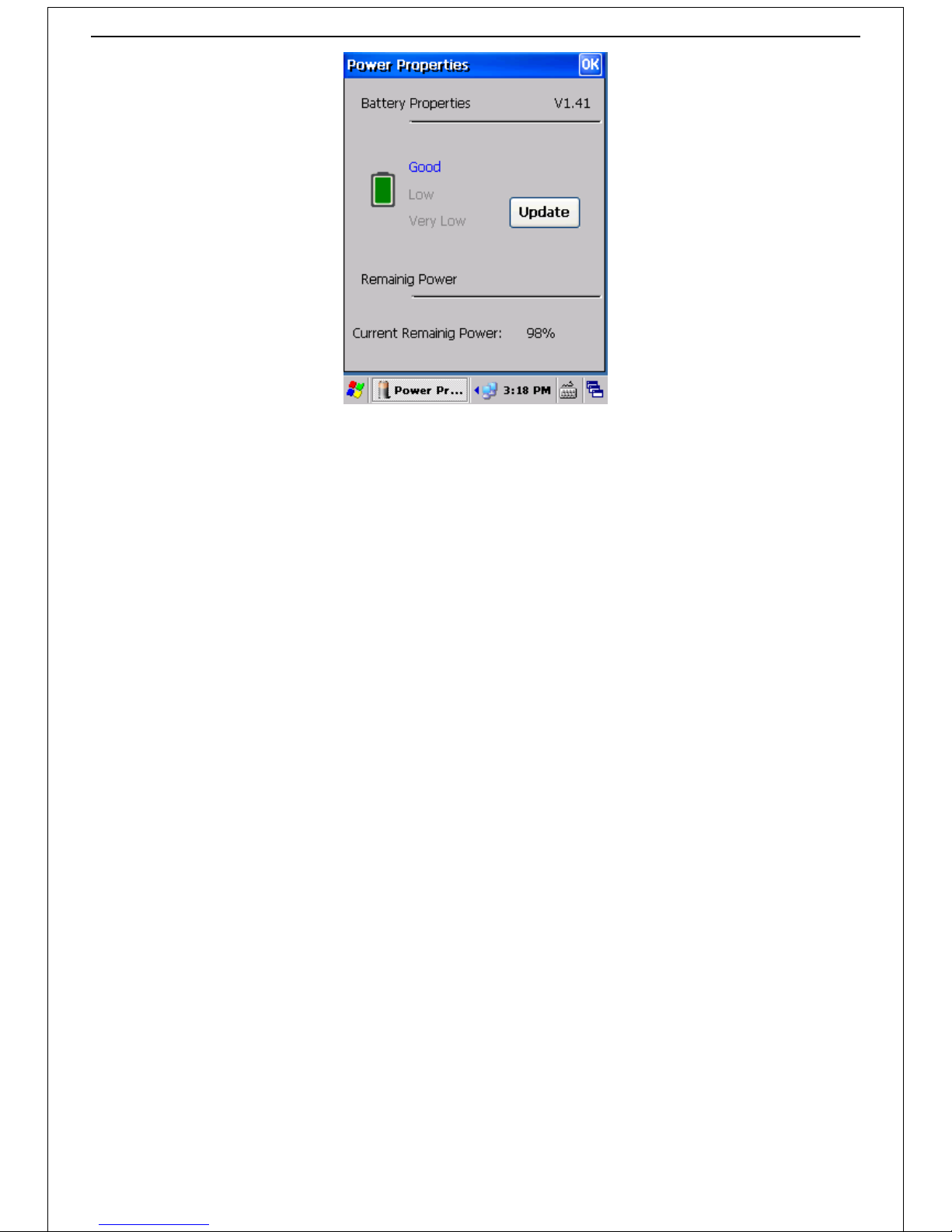
Double-click the power icon to open the page of Power Supply Properties, the current battery and charging status
can be viewed clearly in this interface, as shown in diagram 1.3:
Electrical contact
chip
Li-ion Battery
Powerport
Keep pressing the
on/off key for 3s
Power Button
Page 6
5
Diagram 1.3
Page 7
6
Part 2 Operations
2.1 Install “ActiveSync” program
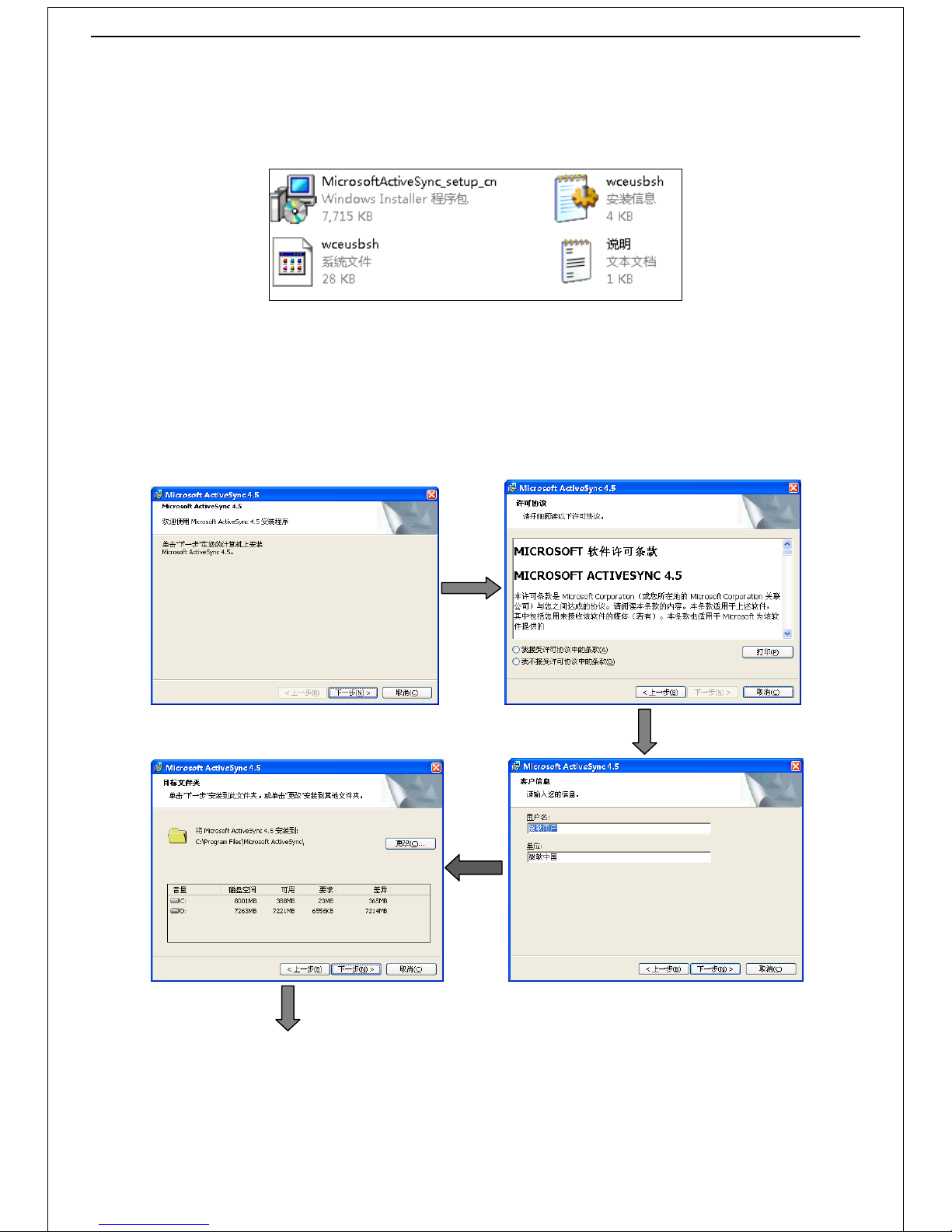
1. Double-click the "ActiveSync4.5" folder to open the interface shown in diagram 2.1:
Diagram 2.1
2. Double-click the icon "MicrosoftActiveSync_setup_cn" -> click the "next" button to install "MicrosoftActiveSync4.5" -> select
the "I accept the terms of the license agreement" option and click on "next" –> enter information (User name, Unit; If input
nothing, information follow the system default), then click on "next" -> click the "next" button to install the
"MicrosoftActiveSync4.5" program into the default installation folder or click the "change" button to install to the specified
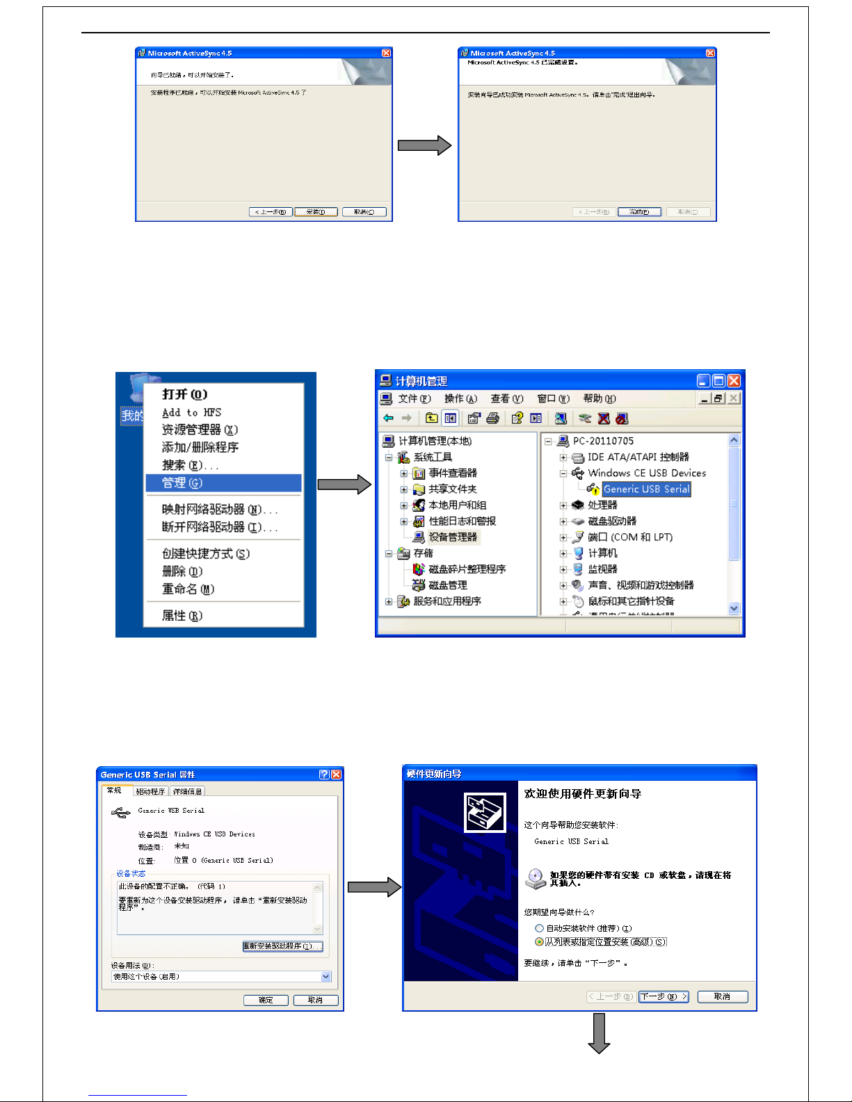
folder -> click on "install" to install the program -> click on "finish" to complete the installation. Operation process is shown
in diagram 2.2 as below:
Page 8
7
Diagram 2.2
2.2 Install “USB sync drive” program
1. Connect the reader to the PC with USB cable.
2. Right-click "my computer" -> select "management" option -> select "device manager" option -> click on the "Windows CE USB
Devices" drop-down box to select "Generic USB Serial" option. Operating process is shown in diagram 2.3 as below:
Diagram 2.3
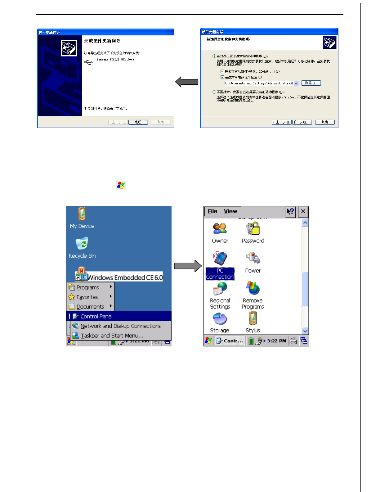
3. Double-click on "Generic USB Serial" -> click the "reinstall driver" button -> select the "Install from the list or specify location"
option, then click on "next" -> click the "browse" button to select the "USB sync drive" file as the storage path -> click the "next"
button to install the USB Step driver -> click on "finish" to close the wizard after the completion of program. Operating process is
shown in diagram 2.4 as below:
Page 9
8
Diagram 2.4
2.3 Scanner synchronize with PC Settings
1. Set the reader connect with PC
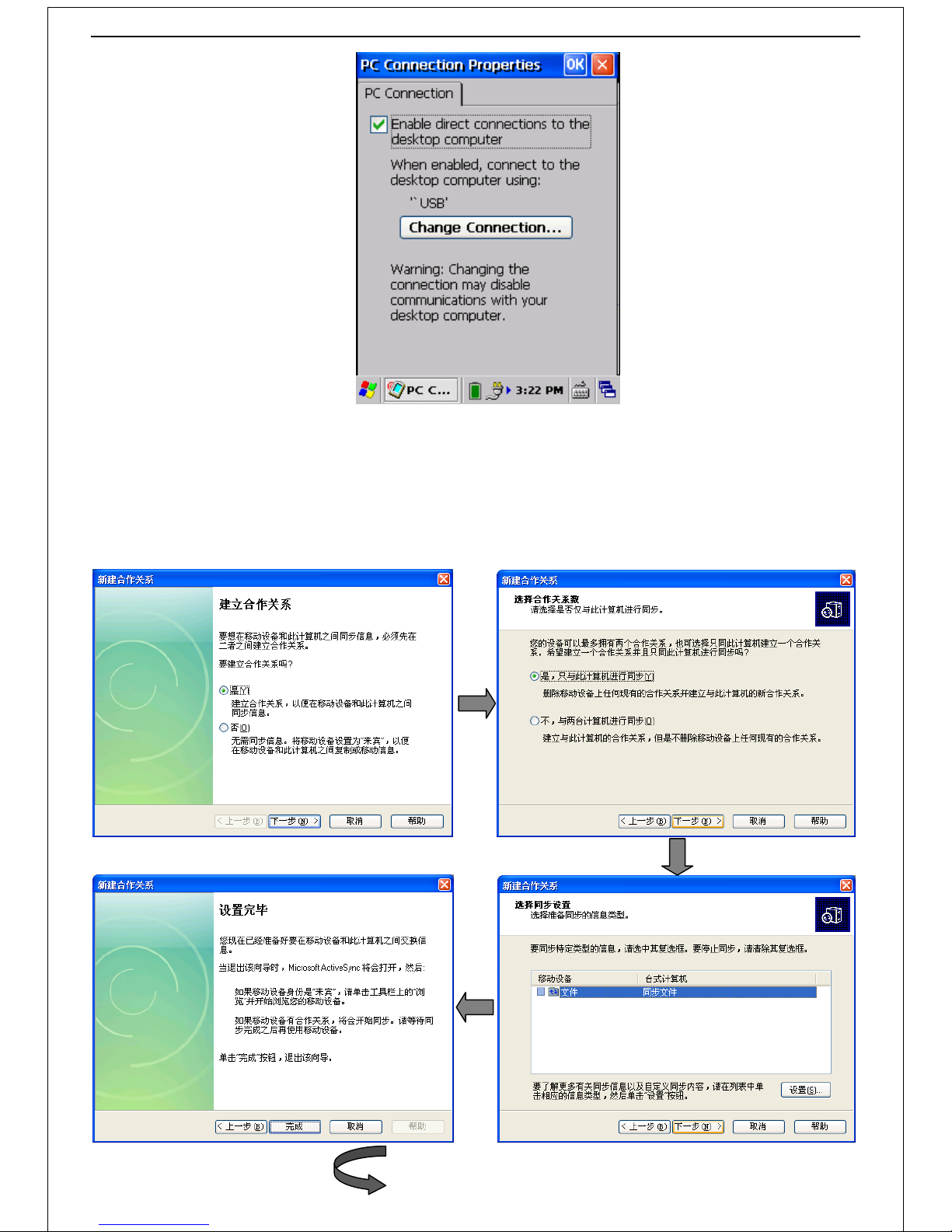
Click on the "system" icon -> select the "Settings" option -> select "control panel" -> double-click ”PC connection” to
open the interface shown in diagram 2.5:
Diagram 2.5
Select "enable a direct link to the desktop computer" option on the page of "PC connection properties". After enabled,
connect the scanner to PC with USB cable (synchronized communication can’t be achieved as option hasn’t been selected). As
shown in diagram 2.6:
Page 10
9
Diagram 2.6
2. Scanner synchronize with PC
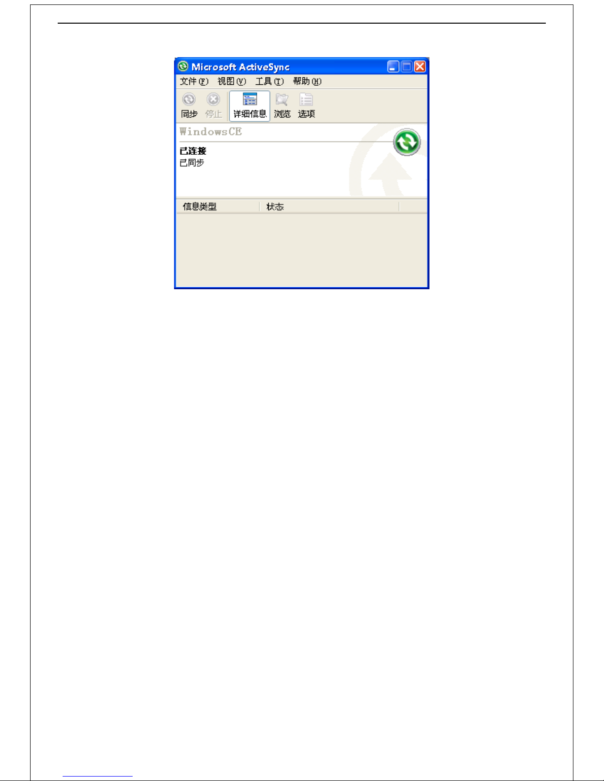
Connect the reader to PC with USB cable. After a successful connection, "partnership" dialog box will appear, select "yes"
option and click on "next" -> select "Yes, synchronize with the computer only" and click on "next" -> click the "next" button ->
click the "finish" button to complete the Settings -> PC pop-up "synchronization" dialog box after set up is completed. Operating
process is shown in diagram 2.7 as below:
Page 11
10
Diagram 2.7
The reader and PC will be allowed to transfer files between each other after synchronized successfully.
Page 12
11
Part 3 Operation of RFID Demo
3.1 UHF
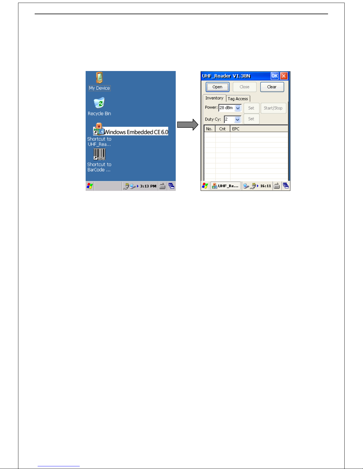
Power on -> double-click the "UHF_Reader V1.38 N" icon to open the operating interface, as shown in diagram 3.1:
Diagram 3.1
Graphic description:
Open: Enable the UHF module
Close: Disable the UHF module
Clear: Clear the contents in the record list
Inventory: Basic operation interface
Tag Access: Reading and writing interface
Power: Set the output power of UHF (0utput power is optional between “0~28”dBm, 28dBm default; Set the
output power according to your needs, have the longest reading range by default; Set the output power
lower as to 21dBm will be helpful to improve the success rate of writing tag. )
Set: Set to update the output Power of UHF (on the right side of "Power" option)
Start/Stop: Start/Stop the searching function (click to start searching tags, click again to stop)
Duty Cy: Set the output power duty ratio (two options: ”1” means the radio output off for 100ms after 400ms
on, ”2” means the radio output off for 100ms after 500ms on. Default setting is ”2”. )
Set: Set to update the output power duty ratio (on the right side of "Duty Cy" option)
1) Label searching
Click on "Open" of the "UHF_Reader V1.38 N" basic operation interface to open the UHF module;
Click on "Start/Stop" or press Start degraded handle button to start searching;
Set the UHF antenna toward the tag;
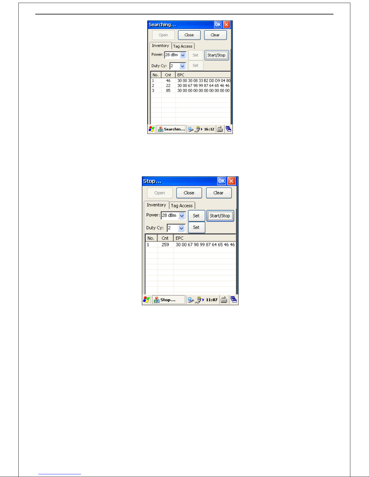
Tag ID will be displayed in the list below (the wording "Searching..." shows on the left upper corner of the "UHF_Reader
V1.38 N" window when the UHF module under searching tag).
As shown in diagram 3.2:
Page 13
12
Diagram 3.2
Click on "Start/Stop" button or loosen the handle button to disable the searching function (the wording "Stop..." shows on
the left upper corner of the "UHF_Reader V1.38 N" window when set in standby). As shown in diagram 3.3:
Diagram 3.3
"Clear" button is used to clear the contents in the record list.
Click the “Close” button to close the program when searching operation is in no needed.
2) Read/Write
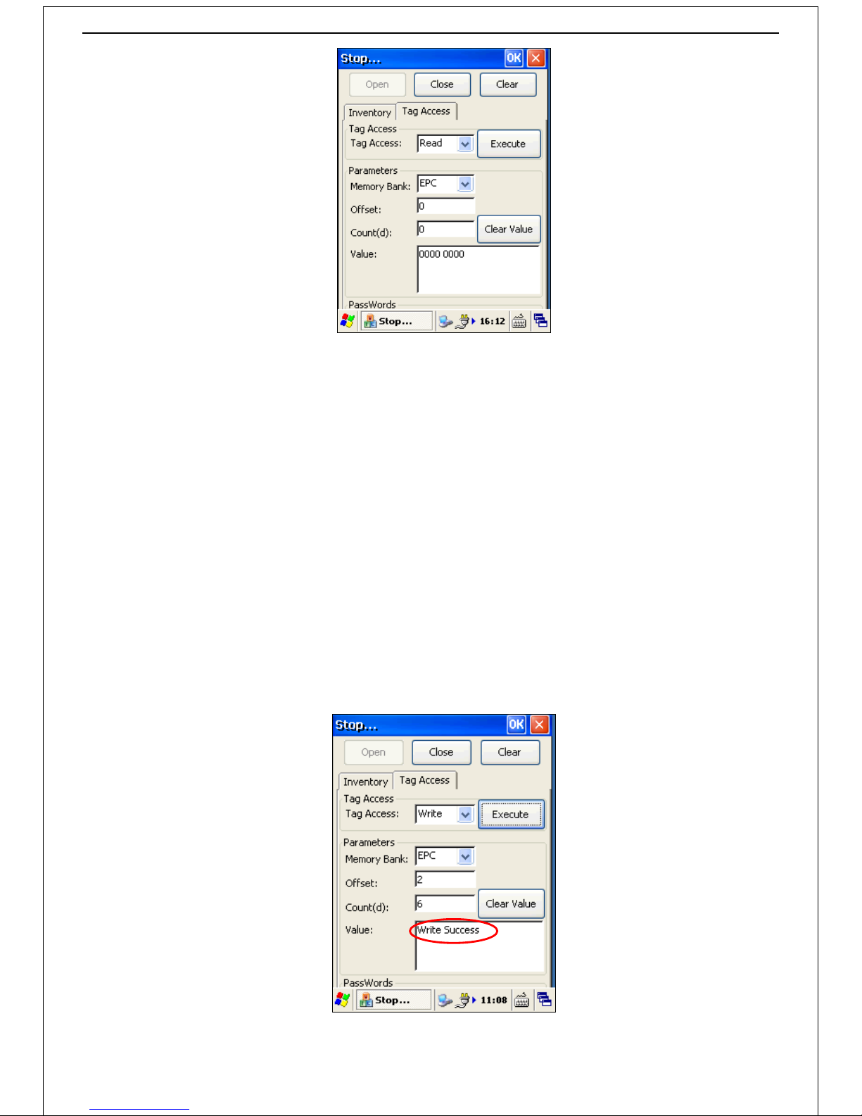
Click "Tag Access" to open the page, as shown in diagram 3.4:
Page 14
13
Diagram 3.4
Text description:
Tag Access: Read/Write mode
Memory Bank: Include RESERVED、EPC、TID、USER; the most frequent set is EPC.
Offset: Start register of selected memory bank section, “2” should be set when EPC was selected.
Count: Preset the reading message length. (Ex, the users accessed EPC section maximum capacity of the
label is 96bits, equals to 6 words.) The system would alert when trying to set over the limit.
Value: Information edit/display box
Read
As shown in diagram 3.4, click on the "Tag Access" drop-down box, select mode to "Read" and "Memory Bank" to "EPC", set
"Offset" to "2" and input "6" into "Count".
Set the UHF antenna toward the tag and then click the Execute button to read the tagID. The corresponding tag information
will be displayed in the "Value" area.
Write
As shown in diagram 3.4, click on the "Tag Access" drop-down box, select mode to "Write" and "Memory Bank" to "EPC",
set "Offset" to "2" and input "6" into "Count".
Input the label data into "Value" and then click the Execute button to update the label information. "Write Success" will be
shown in "Value" area after the label has been written successfully. As shown in diagram 3.5:
Diagram 3.5
Page 15
14
3.2 Barcode
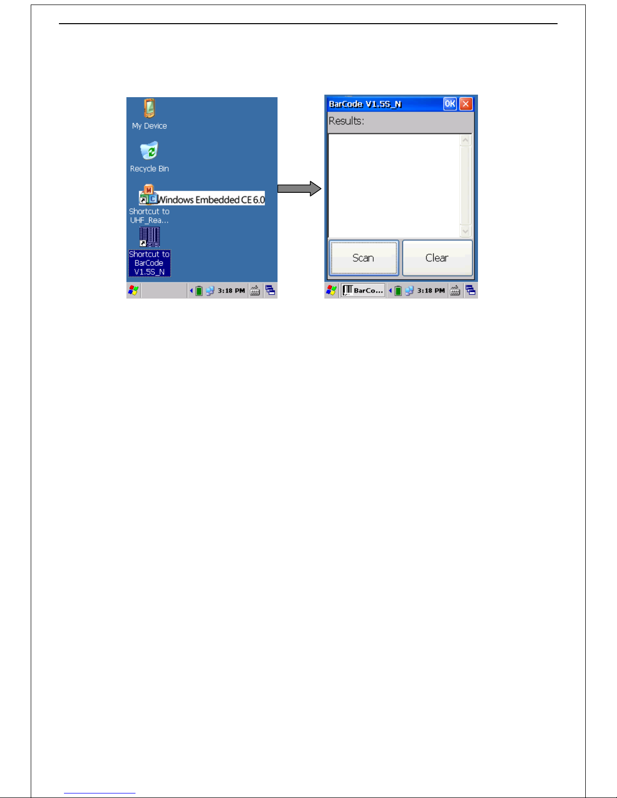
Power on -> double-click the "Barcode Scan " icon on the desktop to launch the Barcode Scan DEMO program, as shown in
diagram 3.6:
Diagram 3.6
Set scanner towards the barcode, you have 3 ways to scan the barcode: click "scan" button、 press the degraded handle button
or press the orange function key (it can be continuous scanning if you hold on pressing the degraded handle button). Click
"remove" button to clear the records of the scanning (system will automatically clear the records when over range 50).
Page 16
15
Part 4 Wireless and Network Settings
4.1 WIFI Connection
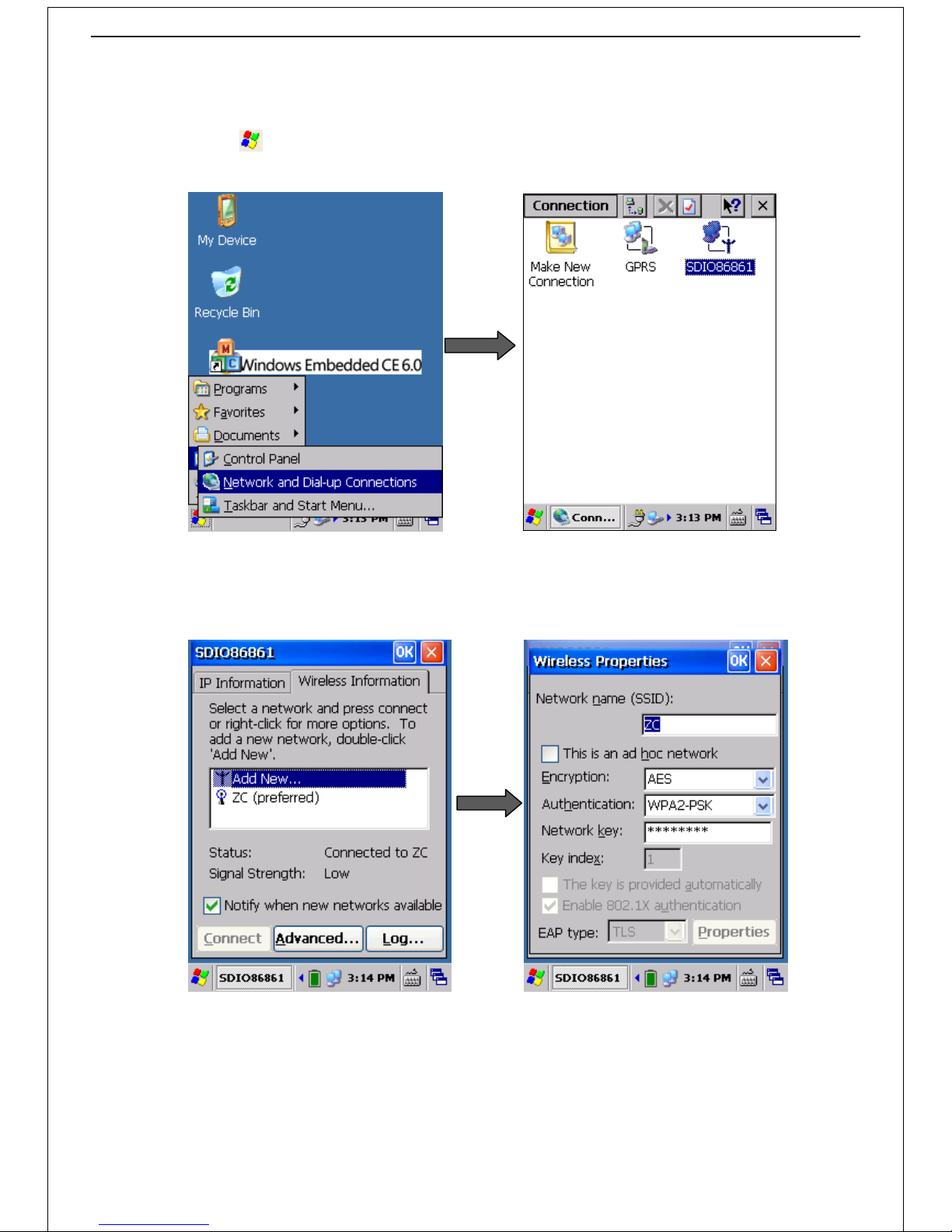
Desktop -> click the icon -> select "Settings" option -> select “network and dial-up connection” option to open the page, as
shown in diagram 4.1:
Diagram 4.1
Double-click "SDI086861" -> select network option in the "wireless information" interface and click “Connect” -> input the
network parameters and password -> click “OK” to launch up. As shown in diagram 4.2:
Diagram 4.2
Page 17
16
4.2 GPRS Connection
4.2.1 Power on
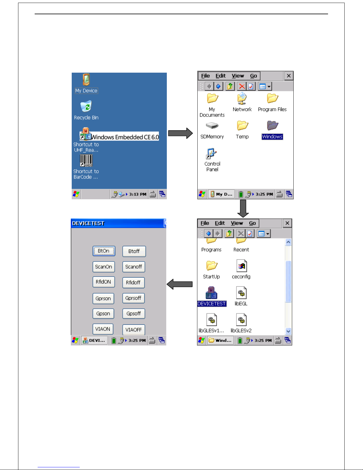
Desktop -> double-click "my device" icon -> open “Windows” folder -> double-click "DEVICETEST" icon -> click “Gprson” button
to power on (the network light flashing) -> click “OK” to save settings -> exit. As shown in diagram 4.4:
Diagram 4.4
Page 18
17
4.2.2 GPRS Connection
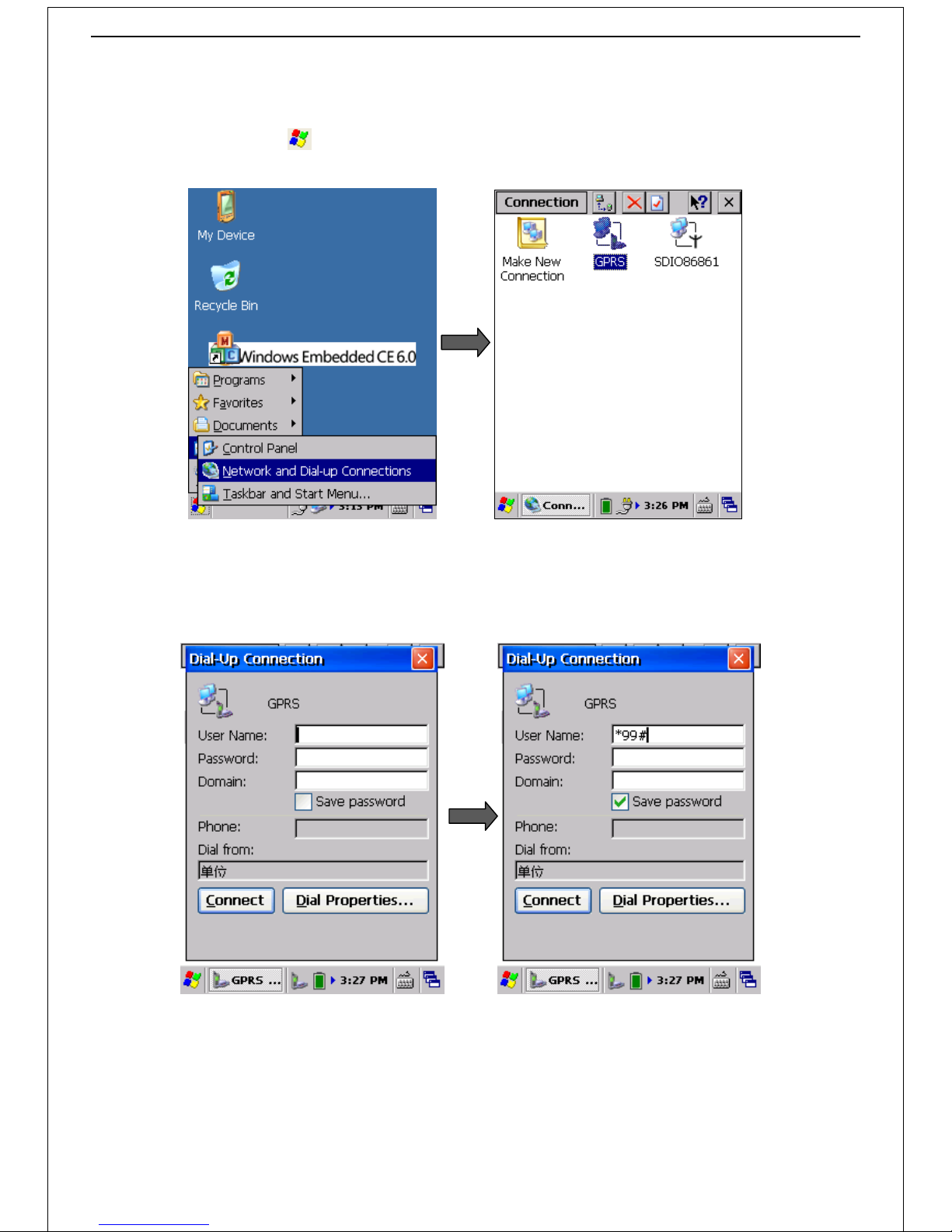
Power on -> click "system" icon -> select "Settings" option -> select "network and dial-up connections" option to open the
operating interface, as shown in diagram 4.5:
Diagram 4.5
Double-click "GPRS" icon -> input user name and password on the "dial-up connection" interface and click “Connect” button to
launch (the default support China mobile GPRS connections, refer to the document "CMC165 GPRS dial-up networking
configuration method.doc" if you want to change operator). As shown in diagram 4.6:
Diagram 4.6
Page 19
18
Part 5 Set the control panel parameters
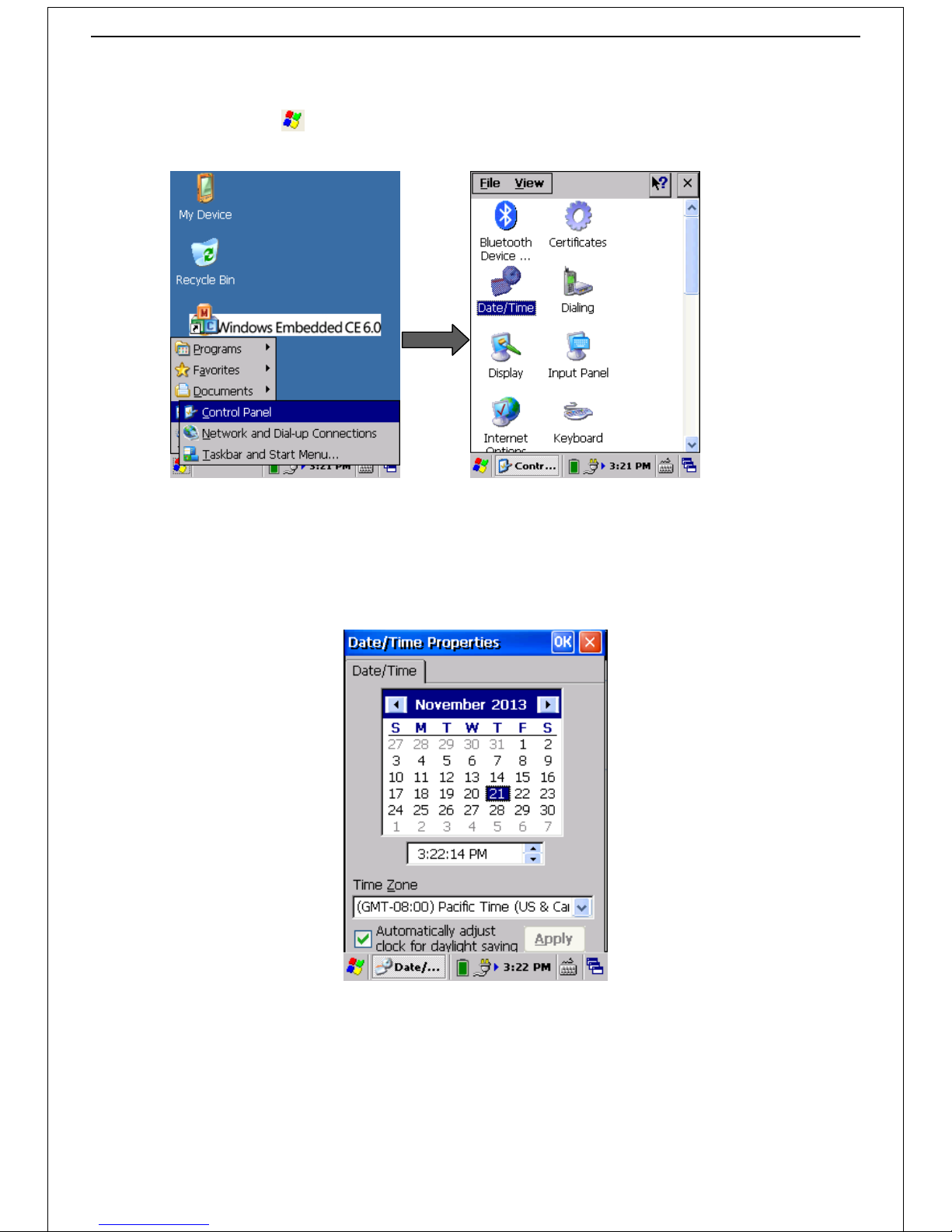
Desktop -> click "system" icon -> select "Settings" option -> click "control panel" icon to open the operating interface , as
shown in diagram 5.1:
Diagram 5.1
5.1 Date/Time
Double-click the "date/time" option (in the "control panel" interface) to open a date/time properties interface; Set date/time
and then click "OK" to save the Settings. As shown in diagram 5.2:
Diagram 5.2
5.2 Background light
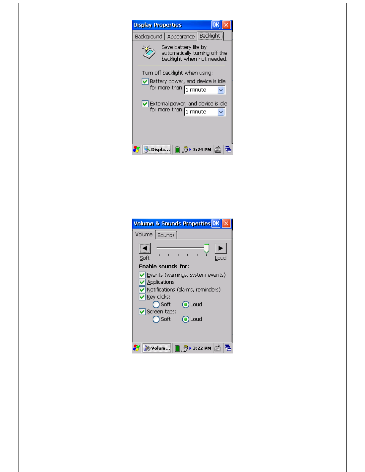
Double-click the "show" icon (in the "control panel" interface) -> select the “background light” option -> set the parameters and
click "OK" to save these settings. As shown in diagram 5.3:
Page 20
19
Diagram 5.3
5.3 Volume and Sound
1)Volume
Double-click the "volume and sound" icon (in the "control panel" interface) -> select "volume" option to enter the volume
setting interface -> set the volume parameters and click "OK" to save these settings. As shown in diagram 5.4:
Diagram 5.4
2)Sound
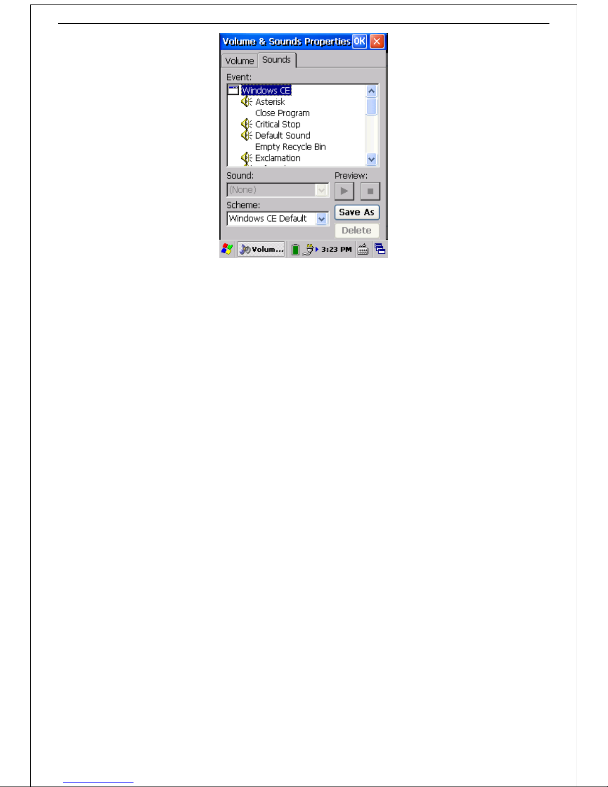
Double-click the "volume and sound" icon -> select "voice" option to enter the sound setting interface -> set up the voice
parameters and click "OK" to save these settings. As shown in diagram 5.5:
Page 21
20
Diagram 5.5
Page 22
21
Add1:Quick trouble shooting guide
Equipment and System
Q1:Can't enable the reader?
A1:Maybe battery is low, restart again after charging.
A2:Lightly press the "reset button" to restart.
Q2:Touch screen is no response?
A: Maybe the touch screen is too dirty, wipe the screen with clean cloth.
Q3:Can't charge?
A1:Check to confirm whether the scanner has connected well to the charge block.
A2:Make sure the charge block has connected to the mains.
Q4:Can't connect GPRS?
A1:Make sure you have enabled GPRS.
A2:Confirm the SIM card isn’t owe fees.
Scanning
Q1:Display garbled words?
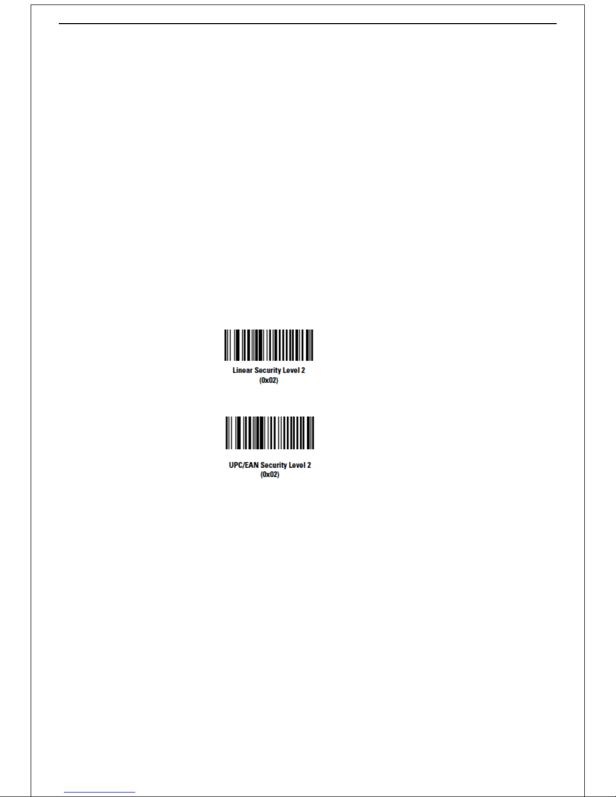
Scan the following barcode to set the standard barcode:
All code types must be successfully read twice before being decoded;
If mis-decodes of poorly printed bar code occur, and the mis-decodes are not limited to characters 1、2、7 and 8, select this
security level;
Q2:Scanning head can't scan the barcode?
A1: Check the barcode to make sure it is unbroken.
A2: Make sure the barcode is within the scan range.
A3: Check the type of barcode.
Note: If you still cannot rule out the fault according to the above steps, we advise you to restart the scanner.
Page 23

Add2: Maintenance
Can’t be used in corrosive environment ;
Dropped from high or strongly impact are not allowed;
Make sure the scanner is power off when you want to insert SIM card.
Do not use sharp objects to touch the screen in order to avoid damages ;
Clean the screen with soft cloth.
Do not use scanner in direct sunlight, high humidity and a location near heat sources;
Dedicated battery charger and battery is requisite.
Discard used lithium ion battery in accordance with the relevant provisions. Never end in fire, or you may cause explosion.
Add3: Customer service
Warranty period is one year without damage to natural disaster and man-made factors;
The product Shall not return once sold, except for product quality problem need to repair or replace;
Please package the reader and attachment carefully if maintenance service is needed.
Page 24

1
 Loading...