

CMM-9304-V2.1
Bluetooth 4.2/5.0 compatible module
SPEC No.
CMM-9304-V2.1
BLE module
Revision
2.8
State
2017-11-13
C-MAX printed
2017-11-13
Version
English
Page
1 of 11
C-MAX
This Module is limited to OEM installation ONLY
1.0 Description
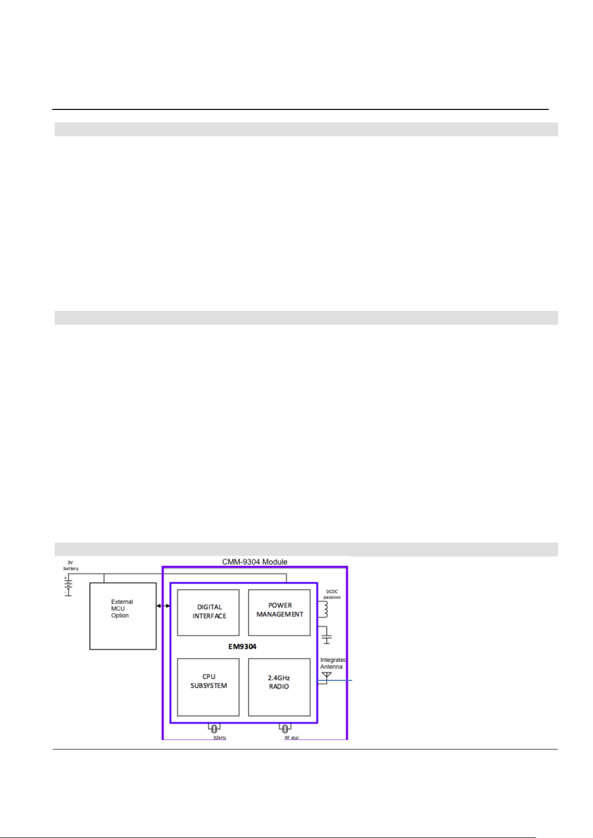
The CMM-9304-V2.1 module is a miniaturised Bluetooth® Low Energy module based on EM
Microelectronic's low power fully integrated Bluetooth® low energy single-chip EM9304. Built in with a
highly efficient PCB antenna, this small sized, low cost module boasts one of the best power
consumption characteristics combined with outstanding Bluetooth Low Energy performances.
The flexible architecture of the EM9304 allows it to act as a companion IC to any ASIC or MCU-based
product, or as a complete System-on-Chip (SoC).
The module offers various possibilities of control via a simple SPI/UART interface: Host Controller
Interface (HCI) with the internal Bluetooth® v5.0 link layer; proprietary Application Controller Interface
(ACI) with the in-built Bluetooth® v4.2 stack, several profiles, and over-the-air firmware (FOTA)
updating routines.
1.1 Features
o Utilize EM Microelectronic’s Bluetooth® 5.0 subsystem qualified (QDID 93999) EM9304 chip
o Concurrent Master and Slave roles BLE compliant to Bluetooth® 5.0 specification
o Embedded Bluetooth® 4.2 stack and profiles, low-power Bluetooth® 5.0 physical layer, Link Layer
with security engine, and a Host Controller Interface (HCI)
o Low average current consumption
3.0 mA typical peak receiver current (3V powered)
5.2 mA typical peak transmitter current at 0.4 dBm (3V powered)
1.0 uA connect sleep mode current (3V powered)
0.005 uA disable mode current (3V powered)
o High sensitivity : -93dBm Bluetooth low energy receiver sensitivity for 255 bytes PDU
o Small-sized (14.0mm x 17.0mm)
o Integrated Antenna on module, with external antenna connection option
o Wide range programmable RF output (-34 to +6.1 dBm) for current consumption optimization.
o No Tuning necessary
o SPI interface/UART interface to external micro-controller
1.2 Block Diagram
CMM-9304-V2.1
Bluetooth 4.2 / 5.0 compatible module
SPEC No.
CMM-9304-V2.1
BLE module
Revision
2.8
State
2017-11-13
C-MAX printed
2017-11-13
Version
English
Page
2 of 11
C-MAX
Module Pin
Number
Module Pin
Name
Input / Output
relative to module
Pin Description
1
ANT
I
RF single ended antenna connection pin (50 ohm)
2
GND
GND
Ground Connection
3
VBAT
Supply
VCC Voltage Supply
4
VIO
Supply
GPIO Voltage Level
5
EN
I
Chip Enable (Active HI)
6
TM / GPIO5
I/O
RESET(Active Low)/Logic Input/output
7
URX / GPIO6 O UART Data in/ Logic Input/output
8
CSN / GPIO0 I SPI Chip Select (Negated)
9
SCK / GPIO1
I
SPI Clock Input
10
MISO / GPIO2
I/O
SPI Data Out
11
MOSI / GPIO3
I/O
SPI Data In
12
UTX / GPIO7 O UART Data Out/ Logic Input/output
13
RDY / GPIO4 O SPI Ready signal
14
TCK / GPIO8
I/O
JTAG/ Logic Input/output
15
TDO / GPIO9
I/O
JTAG/ Logic Input/output
16
TDI / GPIO10
I/O
JTAG/ Logic Input/output
17
TMS / GPIO11
I/O
JTAG/ Logic Input/output
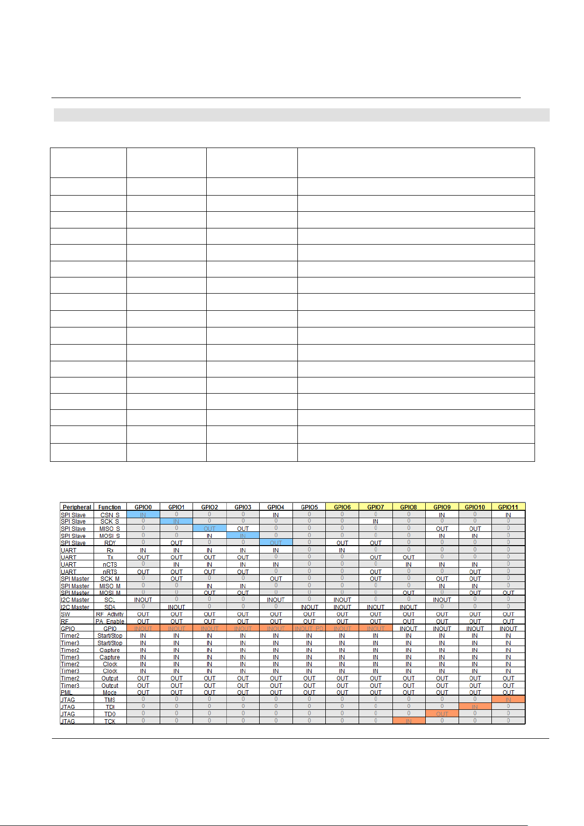
1.2.1 Typical Module Pin Assignment
SPI Slave Mode configuration
This module can also be configured into other configuration modes and the pins will be converted to
different definitions as the following table
:
CMM-9304-V2.1
Bluetooth 4.2 / 5.0 compatible module
SPEC No.
CMM-9304-V2.1
BLE module
Revision
2.8
State
2017-11-13
C-MAX printed
2017-11-13
Version
English
Page
3 of 11
C-MAX
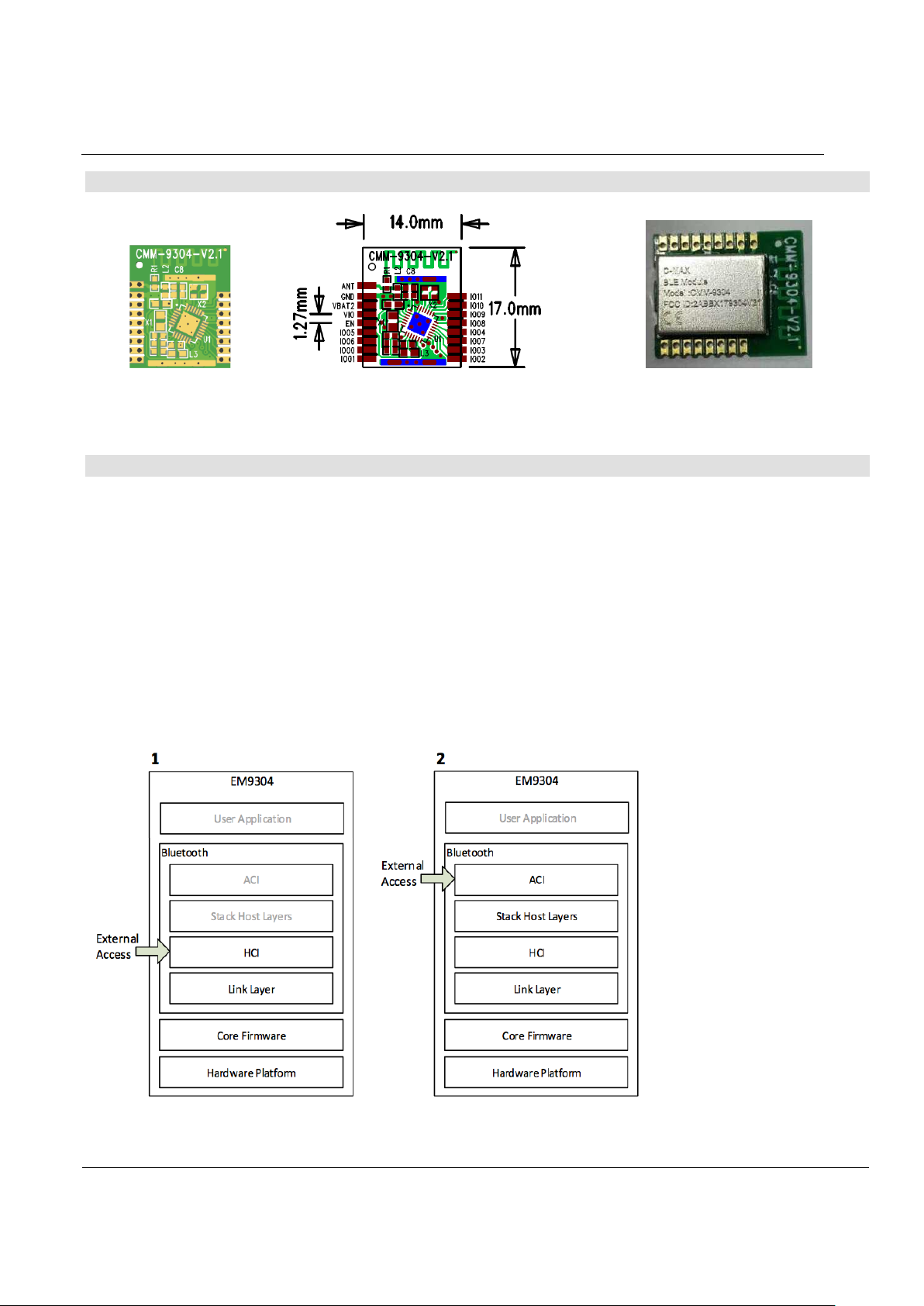
1.2.2 Module Dimensions and Pinnings
Module Thickness (excluding pin header connectors, including shielding) = 2.8 mm max.
1.3 Controller and Companion Modes of Operation
Module as Controller (1 in figure below)
The CMM-9304 module can be used with an external host where the user application and the host
layers of the stack reside in the external processor or host controller. Interaction with the module
occurs through the standard HCI commands (defined in the Bluetooth Core Specifications, volume 2,
part E) and vendor specific HCI commands via the SPI/UART interface detailed in section 3 below.
Module as Companion (2 in figure below)
The CMM-9304 module can be used with an external host where the user application resides in the
external host, and the stack resides in the EM9304. Interaction with the module occurs through
proprietary ACI commands via the SPI/UART interface.

CMM-9304-V2.1
Bluetooth 4.2 / 5.0 compatible module
SPEC No.
CMM-9304-V2.1
BLE module
Revision
2.8
State
2017-11-13
C-MAX printed
2017-11-13
Version
English
Page
4 of 11
C-MAX
2. SPI Slave Interface
The CMM-9304 module has a Slave SPI to be used for the HCI (or ACI) transport layer.
2.1 SPI Slave Features
The SPI slave block supports following features:
4 wire SPI interface (SCK, CSN, MISO, MOSI) with flow control (RDY output signal).
Half duplex communication. Direction (write/read) is determined by a control byte
Supported SPI clock speed up to 16MHz.
Motorola compliant, clock polarity CPOL = 0 (clock is inactive low), clock phase CPHA = 0
(data is valid on clock rising edge).
All 4 SPI clock polarity/phase configurations.
64 bytes long RX FIFO for reception and 64 bytes long TX FIFO for transmission.
Multi byte transactions (without de-asserting CSN between bytes)
2.2 SPI Slave RDY signal
RDY signal has following meaning depending on SPI transaction phase:
1. Data ready (when CSN = '1')
RDY at '1' SPI Slave has some data to send.
RDY at '0' SPI Slave has no data to send.
2. SPI ready (between CSN falling edge and end of 1st header byte)
• RDY at '1' SPI Slave is ready and SPI transaction can start, SPI Master can transmit another
byte.
• RDY at '0' SPI Slave is not ready and SPI transaction cannot start. SPI masterhas to wait
until RDY is at '1'.
3. Buffer ready (between end of 1st header byte and CSN rising edge)
• RDY at '1' buffer is ready and byte can be written/read

CMM-9304-V2.1
Bluetooth 4.2 / 5.0 compatible module
SPEC No.
CMM-9304-V2.1
BLE module
Revision
2.8
State
2017-11-13
C-MAX printed
2017-11-13
Version
English
Page
5 of 11
C-MAX
• RDY at '0' buffer is not ready and byte cannot be written/read. SPI master has towait until
RDY is at '1'. After asserting CSN and before sending first byte SPI Master
checks if RDY is at '1'. This check shall be done at least T_RDY (100ns) after
asserting CSN. If RDY is at '1' SPI transaction can start, if RDY is at '0' SPI
master has to wait until RDY is at '1'.
An example of write transaction using RDY as a flow control during transaction is shows in Figure 1.
•
• Figure 1: SPI Slave write transaction with active flow control by means of RDY.
2.3 Flow Control using Byte count in Status Byte STS2
A Master with DMA, using the status byte STS2, can run an SPI transaction without interruptions. In
this case SPI Master can ignore RDY during the SPI transaction and use instead the status byte STS2
to determine the maximum length of the SPI transaction. Once maximum length of SPI transaction is
known (from STS2), the SPI Master can configure the DMA to realize the rest of the SPI transaction.
After transmitting the given number of bytes (less than or equal to maximum length determined from
STS2) SPI transaction shall be finished by de-asserting CSN. A new SPI transaction shall start by
asserting CSN and reading status bytes to determine maximum length of this new transaction.
Examples of transactions ignoring RDY are shown in Figure 2 and in Figure 3.
Figure 2: SPI Slave Write Transaction.
Figure 3: SPI Slave Read Transaction.

CMM-9304-V2.1
Bluetooth 4.2 / 5.0 compatible module
SPEC No.
CMM-9304-V2.1
BLE module
Revision
2.8
State
2017-11-13
C-MAX printed
2017-11-13
Version
English
Page
6 of 11
C-MAX
2.4 SPI Slave Operation
Start of the SPI transaction is as follows:
1. The SPI Master asserts CSN to '0',
2. Waits until RDY is at '1'
3. Sends 2 header bytes
4. Reads the status bytes STS1 and STS2.
The status byte STS1 on MISO indicates general status of device. The status byte STS2 on MISO
indicates buffer capacity and it depends on read or write transaction. In case of write transaction STS2
contains the number of bytes which can be written into Slave RX buffer. In case of read transaction
STS2 contains the number of bytes which can be read from Slave TX buffer.
After receiving header bytes (STS1 and STS2), the SPI Master knows how many bytes can be
transferred via SPI in the current transaction (read or write) and the rest of SPI transaction is standard.
The control byte (CTRL) sent on MOSI defines type of transaction (read or write). The second byte on
MOSI is dummy to align with read status data from the Slave and reads 0x00.
The type of transaction (read or write) in half duplex mode is defined by CTRL, the 1
Master:
CTRL = 0x81 for a read transaction.
CTRL = 0x42 for a write transaction.
The STS1 byte contains the status of the SPI slave.
STS1 = 0xC0 when slave is ready.
The STS2 byte contains the maximum number of bytes which can be written into RX FIFO without RX
FIFO overflow during a write transaction, or the maximum number of bytes which can be read from TX
FIFO without TX FIFO underflow during a read transaction.
An SPI transaction can be terminated by the SPI Master at any time. The SPI Master can send only a
header in order to get the status of the RX/TX buffer and then stop the SPI transaction.
st
byte sent by the

CMM-9304-V2.1
Bluetooth 4.2 / 5.0 compatible module
SPEC No.
CMM-9304-V2.1
BLE module
Revision
2.8
State
2017-11-13
C-MAX printed
2017-11-13
Version
English
Page
7 of 11
C-MAX
HCI Command
OGF
OCF
Opcode
PTM Support
EM_SetPublicAddress
0x3F
0x002
0xFC02
No
EM_SetUartBaudRate
0x3F
0x007
0xFC07
No
EM_TransmitterTest
0x3F
0x011
0xFC11
No
EM_TransmitterTestEnd
0x3F
0x012
0xFC12
No
EM_ReadAtAddress
0x3F
0x020
0xFC20
Yes
EM_ReadContinue
0x3F
0x021
0xFC21
Yes
EM_WriteAtAddress
0x3F
0x022
0xFC22
Yes
EM_WriteContinue
0x3F
0x023
0xFC23
Yes
EM_SetPowerModeEx
0x3F
0x024
0xFC24
Yes
EM_SetRfActivitySignalEx
0x3F
0x025
0XFC25
Yes
EM_SetRfPowerLevelEx
0x3F
0x026
0xFC26
No
EM_WritePatchStart
0x3F
0x027
0xFC27
Yes
EM_WritePatchContinue
0x3F
0x028
0xFC28
Yes
EM_WritePatchAbort
0x3F
0x029
0xFC29
Yes
EM_SetClockSource
0x3F
0x02A
0xFC2A
Yes
EM_SetMemoryMode
0x3F
0x02B
0xFC2B
Yes
EM_GetMemoryUsage
0x3F
0x02C
0xFC2C
Yes
EM_SetSleepOptions
0x3F
0x02C
0xFC2D
Yes
EM_SvldMeasurement
0x3F
0x02C
0xFC2E
Yes
EM_SetEventMask
0x3F
0x0A7
0xFC2F
Yes
EM_CalculateCrc32Ex
0x3F
0x0A1
0xFCA1
Yes
3. HCI commands
The HCI commands provide access and control to various capabilities of the Link Layer of the EM9304
controller on the module as defined in the Bluetooth Core Specifications, volume 2, part E. For details
of the standard Bluetooth HCI commands, please refer to the Bluetooth Specification Version 5.0.
In addition, vendor specific HCI commands are also usable for the control and monitor of EM9304 chip
specific features
For details of description of EM Vendor specific commands, please refer to EM9304 datasheet.
4. Recommended PCB layout and foot print
Footprint on main PCB for module connection Recommended PCB layout

CMM-9304-V2.1
Bluetooth 4.2 / 5.0 compatible module
SPEC No.
CMM-9304-V2.1
BLE module
Revision
2.8
State
2017-11-13
C-MAX printed
2017-11-13
Version
English
Page
8 of 11
C-MAX
Specifications
CMM-9304-V2.1
Bluetooth Version
Bluetooth® 5.0 (HCI, LL, PHY), 4.2 (stack)
Input Voltage Range
1.9 V to 3.6V
Frequency Range
2.400 to 2.484 GHz
Modulation
GFSK
On-air data rate
1Mbps
RF channels
40
RF Output Power
- 34 ~ + 6.1 dBm
RF Input Impedance
50 ohms
RF Sensitivity (for 255 byte extended PDU)
-93dBm
Current Consumption (Vcc = 3.0V)
- Off mode (Chip Disable)
0.005 uA typ.
- Connected Sleep mode (LC Xtal)
1 uA typ.
- Active mode (RX)
3.0 mA typ.
- Active mode (TX at 0.4 dBm)
5.2 mA typ.
Operating Temperature Range
- 20 to + 60 degrees C
Operating Humidity
30% ~ 90%
Storage Temperature Range
- 40 to + 85 degrees C
Storage Humidity
30% ~ 90%
5. Key Module Electrical Specifications
6. Temperature Profile for Lead-free Reflow Soldering

CMM-9304-V2.1
Bluetooth 4.2 / 5.0 compatible module
SPEC No.
CMM-9304-V2.1
BLE module
Revision
2.8
State
2017-11-13
C-MAX printed
2017-11-13
Version
English
Page
9 of 11
C-MAX
Part Number
Shielding
Dimensions
(in mm)
DC-DC
Power supply
range (in V)
With pin
connectors?
CMM-9304-V2.1S
Shielded
14.0 x 17.0
Step-down
configuration
1.9 ~ 3.6
No
CMM-9304-V2.1SP
Shielded
14.0 x 17.0
Step-down
configuration
1.9 ~ 3.6
Yes
7. Ordering Information
8. Packaging Information
In trays of 100 pcs per tray
9. FCC Warning Statement
FEDERAL COMMUNICATIONS COMMISSION INTERFERENCE STATEMENT
This equipment has been tested and found to comply with the limits for a Class B digital device,
pursuant to Part 15 of the FCC Rules. These limits are designed to provide reasonable protection
against harmful interference in a residential installation. This equipment generates, uses and can
radiate radio frequency energy and, if not installed and used in accordance with the instructions, may
cause harmful interference to radio communications. However, there is no guarantee that interference
will not occur in a particular installation. If this equipment does cause harmful interference to radio or
television reception, which can be determined by turning the equipment off and on, the user is
encouraged to try to correct the interference by one or more of the following measures:
– Reorient or relocate the receiving antenna.
– Increase the separation between the equipment and receiver.
– Connect the equipment into an outlet on a circuit different from that to which the receiver is
connected.
– Consult the dealer or an experienced radio/TV technician for help.
9.1 Caution
Any changes or modifications not expressly approved by the party responsible for compliance could
void the user's authority to operate the equipment.
This device complies with Part 15 of the FCC Rules. Operation is subject to the following two
conditions:
(1) This device may not cause harmful interference and
(2) This device must accept any interference received, including interference that may cause undesired
operation.
9.2 FCC Radiation Exposure Statement
This equipment complies with FCC radiation exposure limits set forth for an uncontrolled environment.
This equipment should be installed and operated with minimum distance 20cm between the radiator &
your body
This device and its antenna(s) must not be co-located or operating in conjunction with any other
antenna or transmitter.

CMM-9304-V2.1
Bluetooth 4.2 / 5.0 compatible module
SPEC No.
CMM-9304-V2.1
BLE module
Revision
2.8
State
2017-11-13
C-MAX printed
2017-11-13
Version
English
Page
10 of 11
C-MAX
9.3. Important Note
The module is limited to OEM installation ONLY
1. We hereby acknowledge our responsibility to provide guidance to the host manufacturer in the event
that they require assistance for ensuring compliance with the Part 15 Subpart B requirements.
2. The host manufacturer is responsible for additional testing to verify compliance as a composite
system. When testing the host device for compliance with the Part 15 Subpart B requirements, the host
manufacturer is required to show compliance with the Part 15 Subpart B while the transmitter module(s)
are installed and operating. The modules should be transmitting and the evaluation should confirm that
the module’s intentional emissions are compliant (i.e. fundamental and out of band emissions) with the
Radio essential requirements. The host manufacturer must verify that there are no additional
unintentional emissions other than what is permitted in the Part 15 Subpart B or emissions are
complaint with the Radio aspects.
This module is intended for OEM integrator. The OEM integrator is still responsible for
1. ensuring that the end-user has no manual instructions to remove or install module
2. the FCC compliance requirement of the end product, which integrates this module.
3. Appropriate measurements(e.g. 15 B compliance) and if applicable additional equipment
authorizations (e.g. Verification, Doc) of the host device to be addressed by the integrator/manufacturer.
4. The separate approval is required for all other operating configurations, including portable
configurations with respect to Part 2.1093 and different antenna configurations
5. 20cm minimum distance has to be able to be maintained between the antenna and the users for the
host this module is integrated into. Under such configuration, the FCC radiation exposure limits set
forth for an population/uncontrolled environment can be satisfied.
6. Any changes or modifications not expressly approved by the manufacturer could void the user's
authority to operate this equipment.
7. That module is limited to installation in mobile or fixed applications, according to Part 2.1091(b)
8. The maximum antenna gain required for authorized antennas per Part15. 204 (including ant. spec.)
The user manual of the end product should include
In the users manual of the end product, the end user has to be informed to keep at least 20cm
separation with the antenna while this end product is installed and operated. The end user has to be
informed that the FCC radio-frequency exposure guidelines for an uncontrolled environment can be
satisfied. The end user has to also be informed that any changes or modifications not expressly
approved by the manufacturer could void the user's authority to operate this equipment. If the size of
the end product is smaller than the palm of the hand, then additional FCC part 15.19 statement is
required to be available in the users manual: This device complies with Part 15 of FCC rules. Operation
is subject to the following two conditions: (1) this device may not cause harmful interference and (2)
this device must accept any interference received, including interference that may cause undesired
operation.
10. RED Statement
This device is pending for compliance with the essential requirements and other relevant provisions of
Directive 2014/53/EU

CMM-9304-V2.1
Bluetooth 4.2 / 5.0 compatible module
SPEC No.
CMM-9304-V2.1
BLE module
Revision
2.8
State
2017-11-13
C-MAX printed
2017-11-13
Version
English
Page
11 of 11
C-MAX
Disclaimer of Warranty
Information furnished is believed to be accurate and reliable. However C-MAX assumes no responsibility, neither for the consequences of use
of such information nor for any infringement of patents or other rights of third parties, which may result from its use. Specifications mentioned
in this publication are subject to change without notice. This publication supersedes and replaces all information previously supplied. C-MAX
products are not authorized for use as critical components in life support devices without express written approval of C-MAX.
Note
It is not given warranty that the declared circuits, devices, facilities, components, assembly groups or treatments included herein are free from
legal claims of third parties. The declared data are serving only to description of product. They are not guaranteed properties as defined by
law. The examples are given without obligation and cannot give rise to any liability.
Reprinting this data sheet - or parts of it - is only allowed with a license of the publisher.
C-MAX reserves the right to make changes on this specification without notice at any time.
C-MAX Asia Ltd C-MAX Technology Ltd (Shenzhen)
Unit 117, 1/F., Unit 33H,33/F.,
Liven House, International Trade Commercial Building,
61-63 King Yip Street, 3005 Nanhu Road,
Kwun Tong, Kowloon, HK SAR Luohu District, Shenzhen, PR China,
Tel.: +852-2798-5182 Tel: +86-755-25181858
Fax: +852-2798-5379 Fax: +86-755-25181859
e-mail: enquiry@c-max.com.hk email: mandy@c-max.com.cn
 Loading...