

Page 1
CMA Dishmachines
12700 Knott A venue
Garden Grove, CA 92841
Toll Free: 1- (800) 854-6417
Fax: 1- (714) 895-2141
Installation/Operation Manual with Service Re
Undercounter
High Temperature
Dishwasher
Models:
UC65e
placement Parts
CMA Dishmachines
12700 Knott Avenue
Garden Grove, CA 92841
Toll Free: 1 (800) 854-6417
Fax: 1 (714) 895-2141
UC65e
Machine Serial No.
Issue Date: 11.18.13
Manual P/N 0512865 rev. D
For machines beginning with S/N W090217876 and above
Printed in the USA
Page 2

For future reference, record your dishwasher information in the box below.
Model Number__________________________ Serial Number_______________________
Voltage________________Hertz_____________ Phase__________________
Service Agent __________________________________ Tel:______________________
Parts Distributor _________________________________ Tel:______________________
National Service Department
CMA Dishmachines
12700 Knott Avenue
Garden Grove, CA 92841
Toll-free: 1 (800) 854-6417
Fax: 1 (714) 895-2141
ATTENTION:
The model no., serial no., voltage, Hz
and phase are needed to identify your
machine and to answer questions.
The machine data plate is located
on the lower front panel.
Please have this information ready
if you call for service assistance.
COPYRIGHT © 2013 All rights reserved Printed in the USA
Page 3

Revision History
Revision History
• The Revision History can contain part number changes, new instructions, or
information that was not available at print time.
• We reserve the right to make changes to these instructions without notice and without
incurring any liability by making the changes..
• Equipment owners may request a revised manual, at no charge, by calling
CMA Dishmachines at 1 (800) 854-6417.
Revision Revised Serial Number Revision
Date Pages Effectivity Description
6.04.09 All W090217876 Released First Edition
3.15.11 22-23 W090217876 Added motor fan cover to parts list
1.04.11 31 W090217876 Item 5 changed to P/N 0513110
33 Item 6 changed to P/N 0512120
Item 18 changed to P/N 0312840
35 Item 13 changed to P/N 0512855
6.09.11 44-45 W090217876 Item 13 changed to P/N 0312924
46-47 W090217876 Changed door assembly to P/N 0713141
4.19.13 5 All Added hose barb to instructions
24-55 W120631743 Revised pressure gauge piping
26-27 W120631743 Added P/N 109069 thermostat
All Revisedll/draintimer,P/N0713133
30-31 W120631743 Revised pressure gauge piping
34-35 All Added hose barb P/N 0512231
46-47 All AddedDoordripseals,P/N0512953
and P/N 0512954
53-62 All Added parts installation instructions
6.25.13 2-3 All Added hard wiring info to installation
11.18.13 All All Converted 0xxxxxx P/N's to CMA standards
i
Page 4

Model Description
Model Description
UC65e
High temperature hot water sanitizing dishwasher with built-in 40°F/22°C rise booster heater.
208-240VAC/60/1
ii
Page 5

Table of Contents
Table of Contents
Model UC65e Undercounter Dishwasher
Revision History...................................................................................................................i
Model Descriptions ..............................................................................................................ii
Installation ..............................................................................................1
Receiving ....................................................................1
Electrical Connections ................................................2
Water Connections .....................................................4
Drain Connections ......................................................5
Initial Start-up ..........................................................................................6
Booster Fill Switch ......................................................6
Assembly ....................................................................8
Chemical Dispensing Pumps ......................................9
Priming ..............................10
Adjusting............................11
Operation ................................................................................................................13
Normal Wash Mode ....................................................13
Saf-T-Temp .................................................................14
Cleaning and Maintenance ........................................................................15
Maintenance ...............................................................18
Troubleshooting ..........................................................19
Service Replacement Parts .......................................................................21
Electrical Schematic..............................................................................................51
Timer Chart
.............................................................................................52
Service Parts Installation Instructions
Pressure Gauge Piping Change .................................56
Fill/Drain Timer P/N 0713133 .....................................58
Fill/Drain Timer - Theory of Operation ........................................................62
Cleaning ......................................................................15
.......................................................53
Booster Thermostat P/N 109069 ...............................54
iii
Page 6

Blank Page
This Page
Intentionally
Left Blank
iv
Page 7
Installation
Counter-top
Wall
3" [8cm] Min.
34"
[86cm]
Min.
Floor
Receiving
NOTE:
The installation of your dishwasher must be performed by qualied service personnel.
Problems due to improper installation are not covered by the Warranty.
1. Inspect the outside of the dishwasher carton for signs of damage.
2. Remove the carton and inspect the dishwasher for damage.
3. Check for any accessories that may have shipped with your dishwasher.
4. Move the dishwasher near its permanent location.
NOTE:
The installation of the dishwasher must comply with all local electrical, plumbing, health and
safety codes or in the absence of local codes, installed in accordance with the applicable
requirements in the National Electrical Code, NFPA 70, Canadian Electrical Code (CEC),
Part 1, CSA C22.1; and the Standard for Ventilation Control and Fire Protection of
Commercial Cooking Operations, NFPA 96.
CAUTION:
Be careful when lifting and moving the dishwasher to prevent damage to the machine.
NOTE:
The installation of the dishwasher must comply with local health codes.
5. Compare the installation site utility connections with the dishwasher utility connections
and make sure that they are the same.
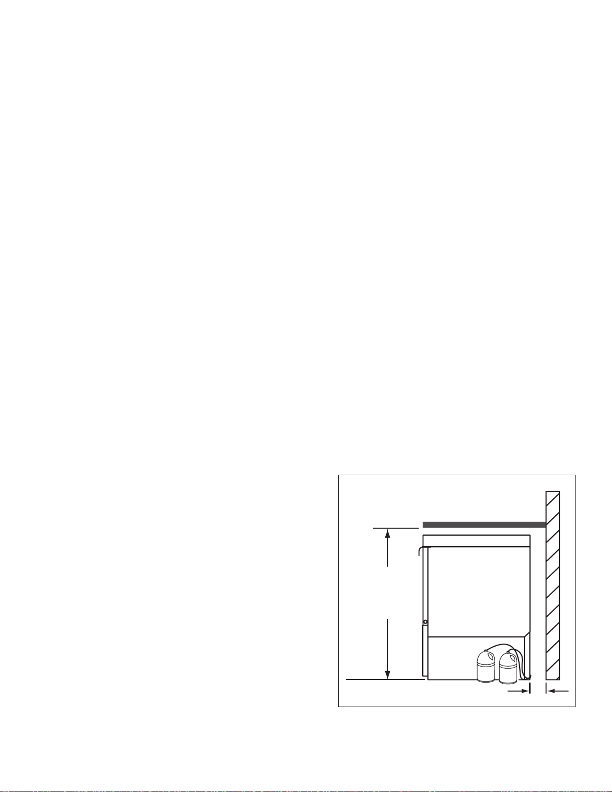
6. The dishwasher can be installed as a free-standing unit or under a built-in counter-top.
The typical counter-top height in most locations is 34" [86cm].
7. Under counter installations should
provide storage space for the
dishwasher chemical supply containers.
Containers must not be placed higher
than 10" [25cm] above the oor.
8. Chemical supply containers should be
placed as close as close to the machine
as possible.
9. Place the dishwasher in its permanent
location.
10. The dishwasher has 4 adjustable feet
for leveling.
11. Level the dishwasher front-to-back and
side-to-side.
1
Page 8
Installation
Electrical Connections
WARNING:
CAUTION:
Permanent damage to the dishwasher may occur if it is improperly
connected to the main electrical supply.
Never install a power cord and plug to the dishwasher nor connect
the dishwasher to a standard or GFI electrical outlet.
GFI
The dishwasher must be hard wired to a dedicated appropriately
sized circuit breaker or service disconnect switch.
Electrocution or serious injury may result when working on an
energized circuit.
Disconnect power at the main breaker or service disconnect switch
before working on the circuit.
Lock-out and tag the breaker to indicate that work is being
performed on the circuit.
ATTENTION:
A qualied electrician must connect the main incoming power to the dishwasher in accordance
with all local codes and regulations or in the absence of local codes in accordance with the
National Electrical Code
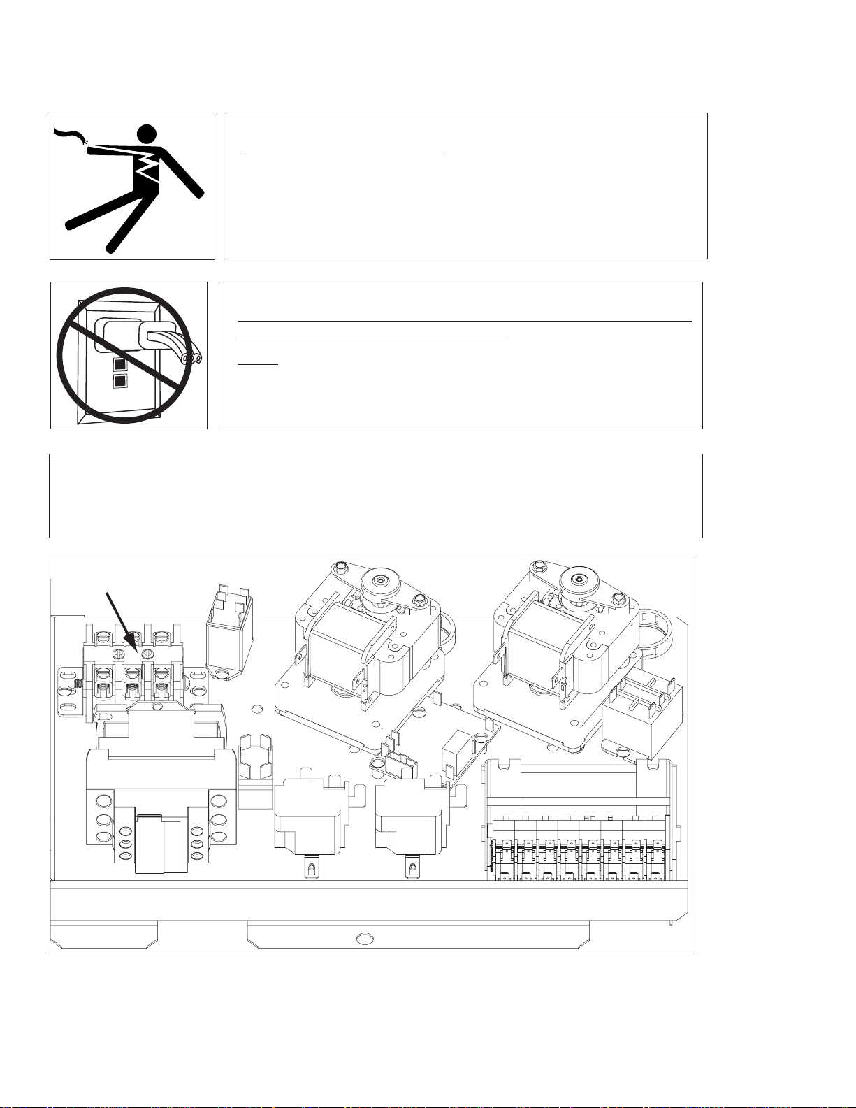
Main Terminal Block
The Main Terminal Block (MTB) is located on the left-rear corner
of the electrical panel.
2
Page 9

Installation
To Dishwasher
Main Terminal Block
Hard Wiring
From Rear of Machine
L1
L2
N
GRD
Cable Bracket
Electrical Connections
1. Refer to the connection diagram below:
2. Machines require a 3-wire plus ground supply which includes a current carrying neutral.
3. Do not use a power cord and plug nor connect to a standard or Ground Fault Interrupter, (GFI),
electrical outlet.
4. The dishwasher must be hard wired to a junction box or service disconnect switch.
5. Power connections must be made at the Main Terminal Block (MTB) on the dishwasher.
The MTB is located on the left-rear corner of the electrical panel behind the front access panel.
(See the illustration at the bottom of page 2.)
To Connect Main Power to the Dishwasher:
1. Remove the lower front access panel of the dishwasher.
2. Locate the electrical mounting panel on the right-side of the machine.
Remove the retaining nut at the top of the panel that holds the
panel in place.
3. Lower the panel and pull it forward to gain access the MTB.
4. Feed the power cable through the cable hole located
on the right side, as viewed from the front of the machine,
SINGLE PHASE POWER CONNECTION
into the interior of the machine.
115/208-240VAC/60/1
GFI
5. Make sure the cable passes through the cable mounting
bracket located near the front-center of the
base and secure the cable with a cable connector.
6. Connect the ground wire to the base of the dishwasher
with the ground screw provided next to the
cable mounting bracket.
7. Feed the remaining cable wires to the Main Terminal
Block and connect according to the connection
diagram to the right.
GRD
L1 L2 N
115VAC
208-240
VAC
HOW TO CONNECT POWER
1. Check the data plate on the front of the
dishwasher for the voltage of the machine.
2. Remove the lower-front access panel.
3. Lower the electrical component bracket.
4. Feed the power cable from the rear of the
dishwasher to the center of the machine
and through the cable bracket.
5. Connect the ground wire to the base of the
dishwasher using the ground screw located
near the bracket.
6. Feed the power leads to the terminal block.
Hard wire the dishwasher using the dishwasher
cable bracket.
7. Connect L1, L2 and a currrect-carrying
neutral to the Main Terminal Block.
8. Main Power connections are complete.
3
Page 10

Installation
Water Connections
Note
Plumbing connections must comply with national, local plumbing and sanitary codes.
IMPORTANT
Make sure that the exible water supply and drain hoses are not kinked.
1. All models have a 6 ft. exible hot water ll hose with a 3/4" GHT connector.
2. A 1/2" or larger main incoming supply line should be installed to the dishwasher.
3. A 1/2" or larger shut-off valve should be installed in the water supply line as close to the
dishwasher as possible for service.
4. The hot water supply must provide a minimum of 140°F/60°C, measured at the dishwasher for
the 40°F/ 22°C rise booster.
5. For the 70°F/39°C rise booster the hot water supply must provide a minimum of 110°F/43°C
measured at the dishwasher.
4
Page 11

Drain Connections
ATTENTION
Do not connect the drain hose to a disposer. The dishwasher will not drain correctly.
1. The dishwasher has a 6ft. 3/4" I.D. drain hose. The maximum drain height
connection must not exceed 3 ft.[9 m].
The recommended drain height is 17" [.4 m] or less above the oor.
2. The drain hose is secured to the rear of the machine by a clamp to maintain a
goose-neck bend in the drain hose.
DO NOT REMOVE THE DRAIN HOSE RETAINING CLAMP.
DO NOT STRETCH THE DRAIN HOSE.
3. A 3/4" hose barb tting is strapped to the drain hose to use in connecting the
drain hose to building drain line.
The service part number for the
hose barb is P/N 0512321.
Installation
4. Install the drain hose to a "WYE" drain tting. Connection to a "TEE" tting will
prevent the dishwasher from draining completely.
5. The maximum drain ow is 8 U.S. gpm/7 Imp. gpm/30 L.P.M.
6. Make sure the drain hose does not kink. Kinks will prevent the dishwasher
from draining completely, and the dishwasher will overow out the front door.
NOTE: DO NOT CONNECT THE DRAIN HOSE TO A DISPOSER.
THE DISHWASHER WILL NOT DRAIN CORRECTLY.
The dishwasher flexible drain hose
must be connected to a WYE fitting.
Do not connect the dishwasher
flexible drain hose to a TEE fitting.
5
Page 12
Initial Start-Up
ON
OFF
BOOSTER
FILL
RINSE
TEMPERATURE
WASH
Booster Fill Switch
A
Filling the Booster
ATTENTION
VERIFY THE CORRECT VOLTAGE IS SUPPLIED TO THE MACHINE
THE CORRECT SUPPLY VOLTAGE IS 115/208-240VAC/60/1.
(Refer to the diagram on page 3.)
Note:
The dishwasher contains a built-in booster heater that was drained prior to shipment
and must be lled with water before operating the dishwasher.
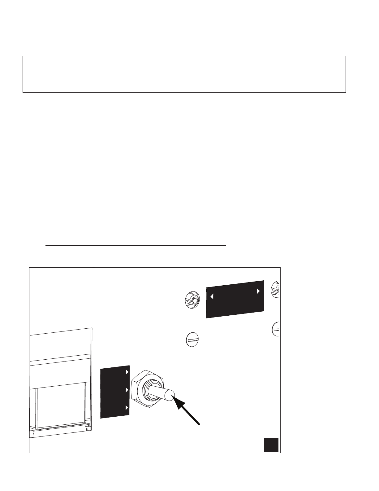
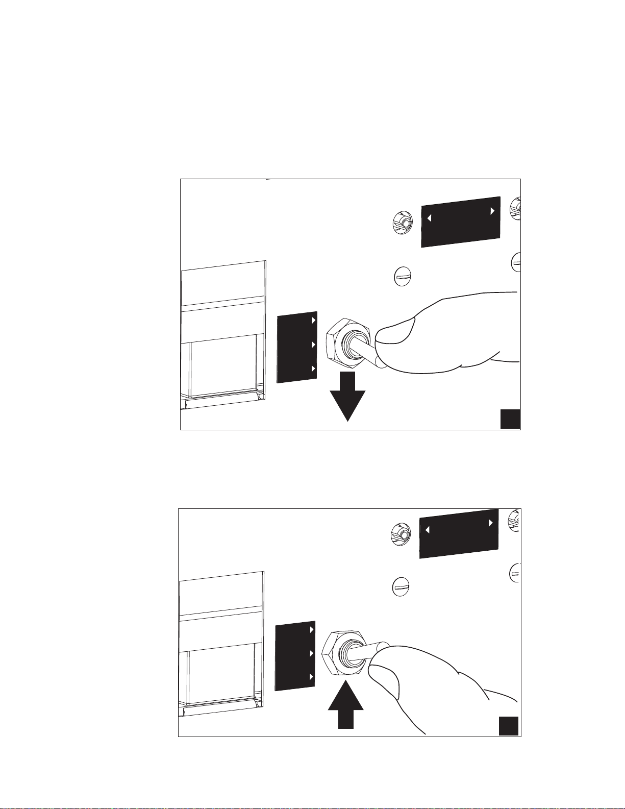
Booster Fill Switch
The booster heater is lled using the Booster Fill Switch. It is located behind the lower front access panel
and on the left-side of the bracket that holds the chemical dispensing pumps (see the photos below).
Fill the booster heater:
1. Make sure that the dishwasher power switch is OFF.
2. Remove the lower front access panel.
3. Locate the booster ll switch. It is in the left-center of the electrical component panel.
4. Make sure the Booster Fill Switch is in the middle position, (OFF).
5. Turn the water supply and the main power supply on.
DO NOT TURN THE DISHWASHER POWER SWITCH ON.
A) Identify the booster ll switch.
6
Page 13
Initial Start-Up
B
ON
OFF
BOOSTER
FILL
RINSE
TEMPERATURE
WASH
C
Filling the Booster (continued)
B) Press and hold the Booster Fill Switch down to the BOOSTER FILL
position until you hear the water spraying inside the dishwasher wash tank,
then release the switch.
RINSE
TEMPERATURE
ON
OFF
BOOSTER
FILL
C) Push the switch up to the ON position and release.
The booster tank is lled.
WASH
7
Page 14
Initial Start-up
Check List
1. Remove any protective lm from dishwasher. Check the interior for foreign material.
2. Make sure that the dishwasher is permanently located.
3. Make sure that all utility connections are complete.
4. Make sure that the exible drain hose and the hot water ll hose are not kinked.
5. Make sure that the chemical supply containers are full and that the chemical pick-up tubes
are installed in the proper containers.
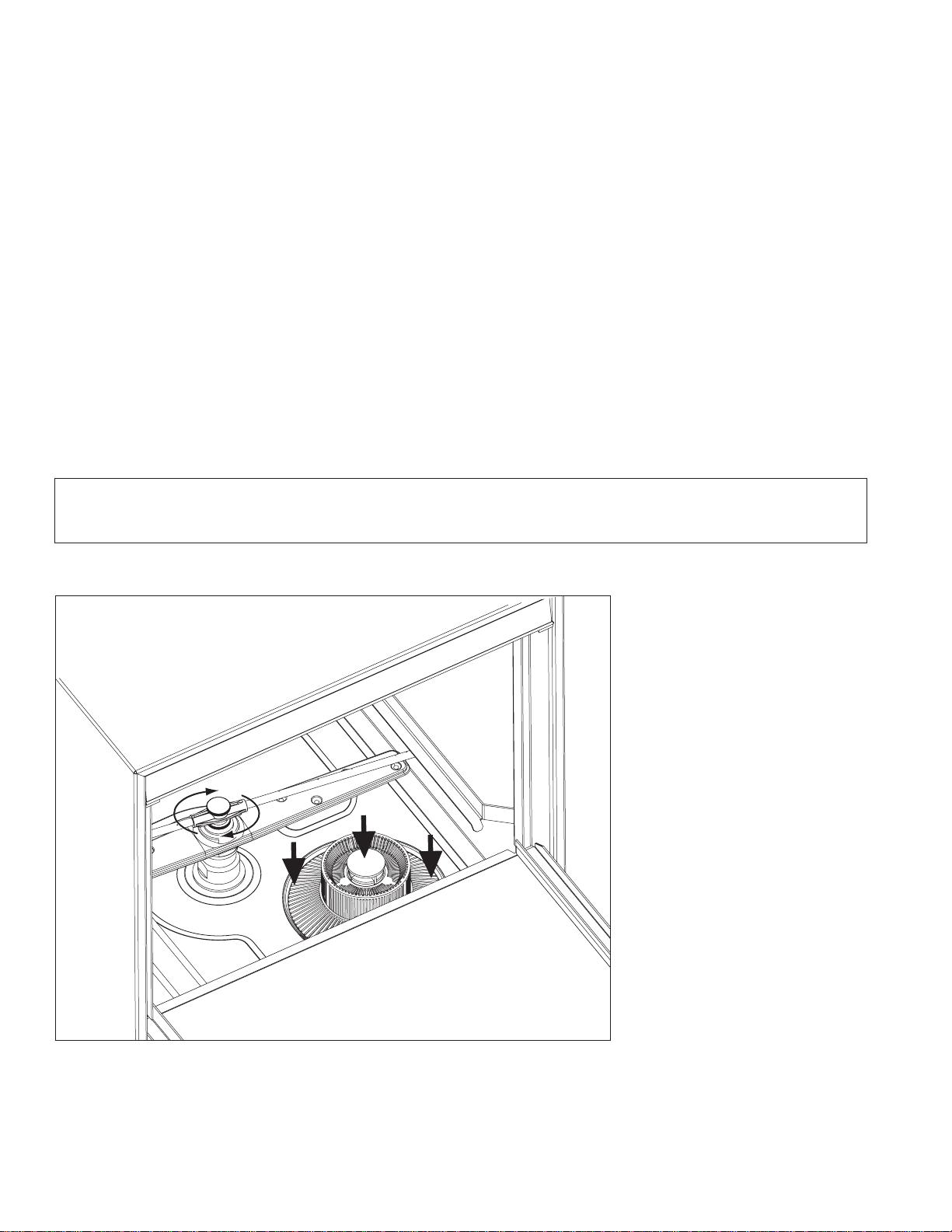
6. Make sure that the sump lter is in place.
7. Make sure that the overow tube is installed and rmly seated in the sump.
8. Make sure that the spray arms are in place and that they spin freely.
9. Fully close the dishwasher door.
10. Turn hot water supply on and check for leaks in the main water supply piping connected
to the dishwasher.
IMPORTANT
During the initial fill, the flowing pressure of the incoming water
is set to 20-22 PSI.
Install the scrap screen, overow tube, and spray arms.
Make sure the spray arms turn freely.
8
Page 15
Initial Start-up
RINSE
TEMPERATURE
WASH
ON
OFF
BOOSTER
FILL
Detergent
Pump
Rinse-aid
Pump
Chemical Dispensing Pumps
ATTENTION
Contact a local chemical supplier for detergent and rinse-aid chemicals. The detergent should be a
non-chlorinated liquid detergent. The chemical dispensing pumps are adjusted by the chemical supplier.
1. The dishwasher is equipped with a built-in detergent dispensing pump and rinse-aid dispensing
pump. (See the photographs below.)
2. The pumps are located on the lower panel behind the lower-front access panel.
3. Each pump is equipped with 6 feet [1.8 m] of pick-up supply tubing, a stiffener tube, and a strainer.
4. A red label marked DETERGENT is attached to the detergent pump inlet tubing.
5. A blue label marked RINSE-AID is attached to the rinse-aid pump inlet tubing.
6. The detergent enters the wash tank compartment through a tting at the right rear of the wash
compartment (see the illustration on the next page).
7. The detergent supply should be a non-chlorinated liquid detergent.
8. The rinse-aid enters the nal rinse piping through a tting located on the upper-left rear side of the
dishwasher. The tting is located near the vacuum breaker (see the illustration on the next page).
The dispensing pumps are located behind the
lower-front access panel.
A stiffener tube, strainer and pick-up
tubing are supplied with the built-in
detergent and rinse-aid pumps.
9. The chemical supplier will choose the appropriate liquid rinse-aid.
10. Your chemical supplier should adjust the dispensers for the supplied product.
11. Place the chemical supply containers as close to the dishwasher as possible.
12. Do not elevate the chemical containers above the nished oor.
9
Page 16

Initial Start-up
Detergent
Injection Point
Chemical Dispensing Pumps (continued)
Chemical Injection Points
The illustrations below show the location of the detergent and the rinse-aid injection points.
Detergent enters the wash tank compartment through a
fitting on the rear wall of the wash tank compartment.
10
Rinse-aid
Injection
Point
The rinse-aid enters the nal rinse piping at the top-rear of
the dishwasher near the vacuum breaker.
Page 17
Initial Start-up
Chemical Dispensing Pumps
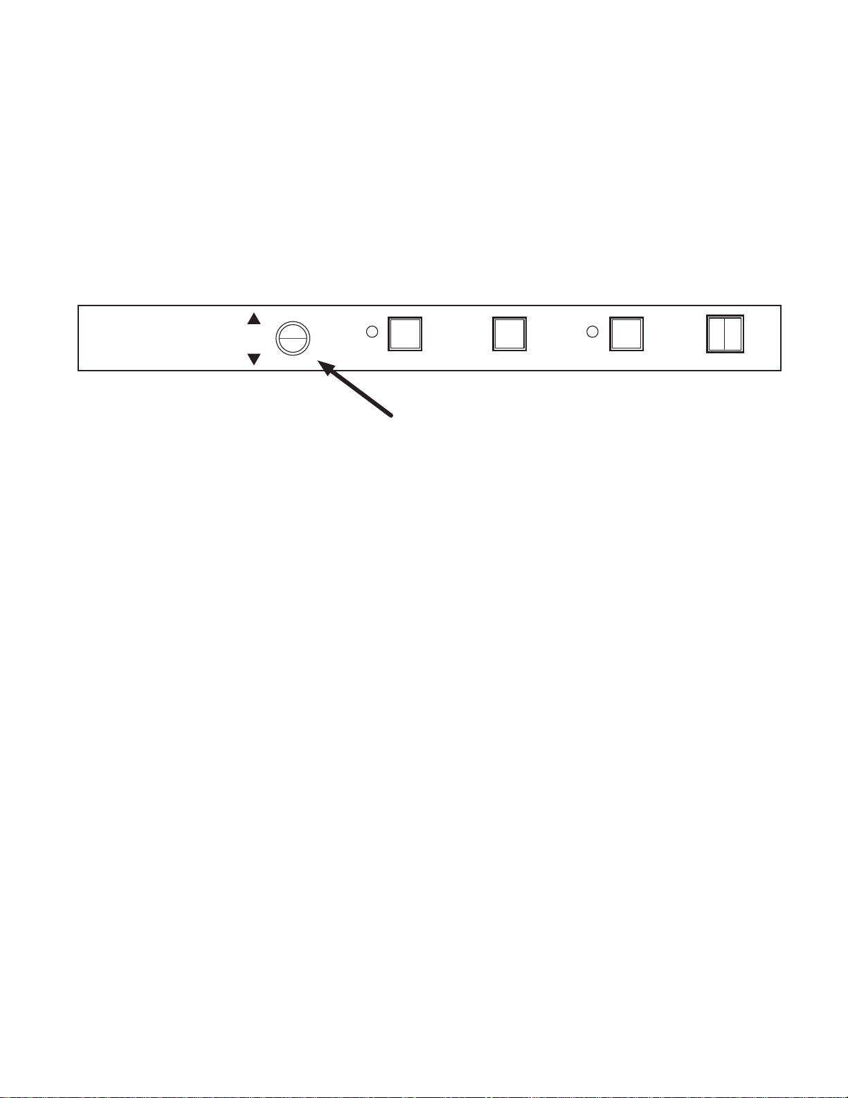
Priming the Chemical Dispensing Pumps
The chemical dispensing pumps must be primed before the dishwasher is operated. A 2-position PRIME
switch is located on the front control panel to do this. The Detergent dispensing pump is primed when
the Prime switch is pushed UP to the DET position. The Rinse-aid dispensing pump is primed when the
Prime switch is pushed DOWN to the R/A position (see below).
DET
R/A
PRIME
POWERSTARTDRAINEXT. WASH
OFFON
Chemical Dispenser Prime Switch
1. Make sure the chemical containers are full and the correct pick-up tubes are in the containers.
2. Turn the dishwasher power switch ON. The switch will illuminate and the dishwasher will ll with
water.
3. Once the ll is complete, open the dishwasher door, then push and hold the prime push button UP
to the DET (detergent) position until detergent is observed entering at the right-rear of the wash
tank compartment.
4. Push and hold the prime push button DOWN to the R/A (rinse-aid) position for 30-seconds.
Release the push button.
5. Close the door.
11
Page 18
Initial Start-up
CCW
Chemical Dispensing Pumps
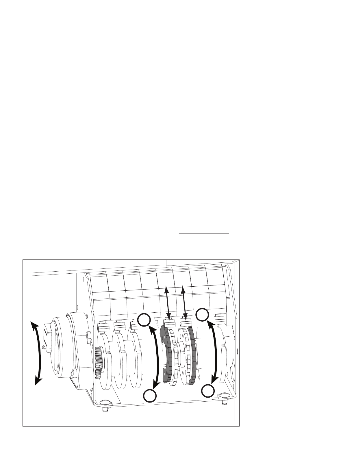
Adjusting the Chemical Dispenser Pumps
The amount of detergent and rinse-aid that are dispensed during the dishwasher cycle are controlled by
adjustable cams on the timer assembly. Variables such as the type of chemicals used and the hardness
of the water supply often require that the timer cam settings must be changed. It is recommended that
the chemical supplier make these adjustments.
(Refer to the illustration below).
Note:
Only the Detergent and the Rinse-aid cams are adjustable. Do not attempt to adjust any other timer cam.
To adjust the chemical dispensing pump timer cams:
1. Remove the lower-front access panel. The timer assembly is located on the right-side of the
electrical component panel.
2. Make sure the dishwasher power is OFF.
3. The detergent timer cam has 2 halves. Hold the stationary right-half of the cam and turn the
left-half of the cam counter-clockwise to increase the amount of detergent that is dispensed.
Turn the left-half clockwise to decrease the detergent dispensed.
4. The rinse-aid timer cam has 2 halves. Hold the stationary left-half of the cam and turn the right-half
of the cam counter-clockwise to decrease the amount of rinse-aid that is dispensed.
Turn the right-half clockwise to increase the amount of rinse-aid dispensed.
HOMING
CAM
WASH
PUMP
DRAIN
PUMP
RINSE
VALVE
DET.
PUMP
RINSE
AID
PUMP
EXTEND
WASH
SAFE-T
TEMP
-
+
D
E
T
E
R
G
E
N
T
R
I
N
S
E
A
I
D
CW
12
-
+
Page 19
Operation
Normal Wash Mode
Follow the instructions below to operate the dishwasher in a Normal Wash Mode. A Safe-T
-Temp feature
holds the dishwasher in a wash mode if the booster heater temperature is below 180ºF/82ºC.
1. Turn the main power on at the main circuit breaker.
2. Install the sump lter, overow tube and spray arms.
3. Make sure the exible drain hose and the exible ll hose are not kinked,
then turn the water supply on.
4. Close the dishwasher front door.
5. Push the dishwasher Power Switch to the ON position.The power switch will illuminate and the
machine will ll with water.
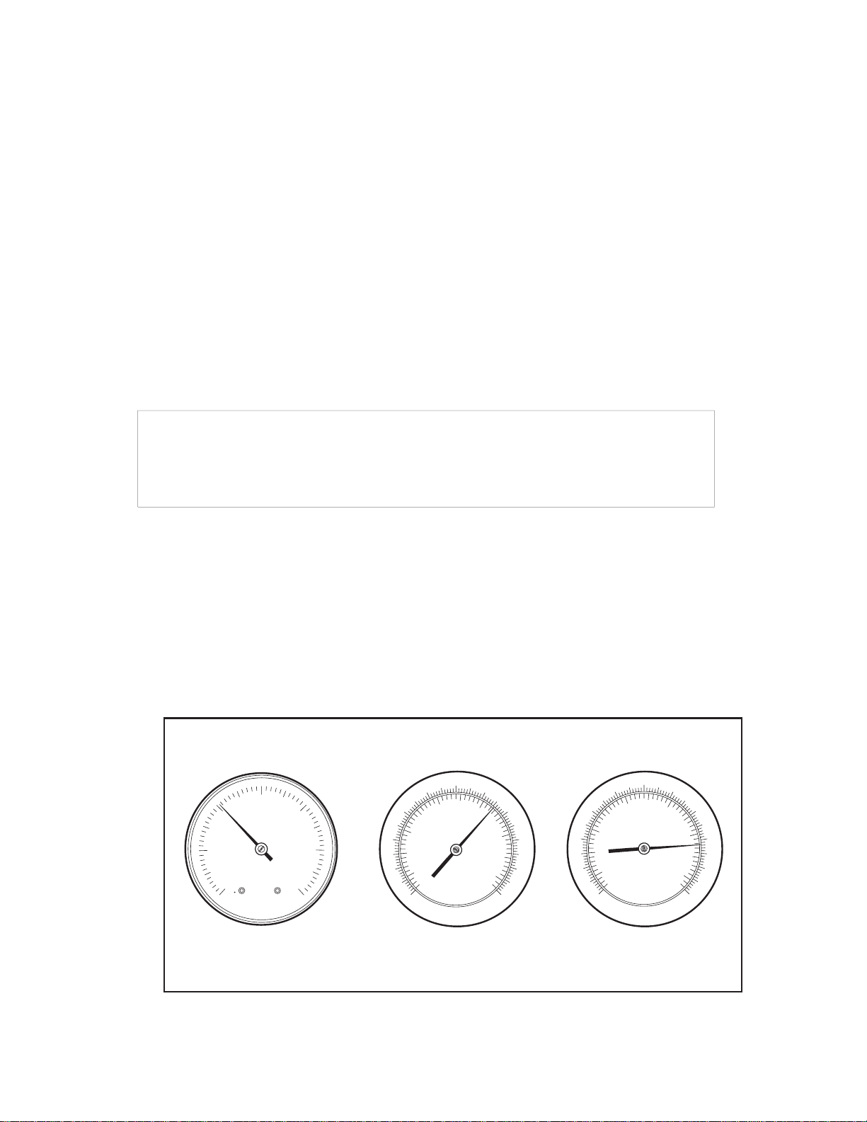
6. Check the pressure gauge as the machine lls and make sure the incoming water pressure is
between 20-22 psi.
7. Wait 15-minutes for the WASH temperature gauge to indicate a minimum of 150ºF/66ºC.
At the beginning of the day, run 2 empty cycles before checking the final rinse
operating temperature. The first cycle will take longer than normal because the
water temperature in the booster is low.
ATTENTION
8. Load soiled wares into the dish rack. Place plates, glasses, cups and bowls in a peg rack.
Place utensils in a single layer in a flat-bottom rack. Place pots and pans in a flat-bottom rack.
Do not overload the dish racks.
9. Slide 1 dish rack into the wash compartment making sure that wares do not interfere with the
rotating spray arms. Do not wash more than 1 dish rack at a time.
10. Close the front door fully, then press and hold the START BUTTON for 1-second. The green
in-cycle light will illuminate and the wash cycle will begin. The wash cycle time runs for
approximately 1-1/2 minutes. (continued on next page)
20-22 PSI
150°F/66°C
180-195°F
82-91°C
120
60
140
100
80
160
180
60
40
200
220
30
10
20
CHAMPION INDUSTRIES, INC.
WINSTON-SALEM,NC
0
40
PSI
50
60
Final Rinse
Pressure
The pressure and temperature gauges are located on the lower-left corner
of the lower-front access panel.
100
40
80
20
60
40
0
20
Wash
Temperature
80
20
120
100
40
20
0
140
60
80
100
Final Rinse
Temperature
160
180
200
220
13
Page 20

Operation
Normal Wash Mode
11. Opening the door when the dishwasher is in-cycle will stop the dishwasher. The cycle will resume
automatically when the dishwasher door is closed fully.
12. The nal rinse cycle begins at the end of the wash cycle and runs for approximately 15-seconds Check the
RINSE temperature gauge during the nal rinse and make sure that it indicates a minimum of 180ºF/82ºC.
The acceptable range of operation is180-195ºF/82-91ºC.
13. At the end of the rinse cycle, the in-cycle light will go out. Open the door and remove the clean
rack of wares. Repeat steps 8-12 for additional dish racks.
14. Refer to the Cleaning Instructions, "After Each Meal Period or every 8 Hours of Operation", on
page 15 for the procedures to drain and clean the dishwasher.
Safe-T-Temp Mode
The nal rinse water temperature must be a minimum of 180ºF/82ºC during the final rinse cycle to ensure that all
wares are sanitized. If for any reason, the hot water temperature in the booster tank cannot provide this temperature,
the dishwasher will enter a Safe-T-Temp Mode of operation and extend the cycle time.
The Safe-T-Temp changes the Normal Operation Mode as described below:
1. The Safe-T-Temp constantly monitors the water temperature inside nal rinse booster.
2. If the temperature inside the booster heater falls below 180ºF/82ºC then the Safe-T-Temp
will extend the wash cycle time until the booster heater water temperature reaches the proper
temperature.
3. The in-cycle light will remain illuminated during the Safe-T-Temp Mode.
4. The RINSE water temperature gauge must be monitored to ensure that a minimum of
180ºF/82ºC is maintained during the rinse cycle.
5. The temperature range for the final rinse water is180-195ºF/82-91ºC.
6. An extraordinarily long wash cycle may indicate a low incoming water temperature or a
problem with the booster heater operation.
(continued)
DO NOT REMOVE WARES UNTIL THE FINAL RINSE CYCLE HAS
SANITIZED THE WARES AND THE GREEN CYCLE LIGHT GOES OUT.
Extended Wash Mode
The Extended Wash Mode is used to wash heavily soiled items such as pots, pans and other wares that
require more washing time than the standard 100-second Normal Wash Mode.
The dishwasher will remain in the Extended Wash Mode until the operator exits the mode.
1. Load a dish rack into the dishwasher, close the door.
2. Press and hold the START button for 1-second then release.
3. The green in-cycle light will illuminate and the dishwasher will begin a normal wash cycle.
4. Press the EXT WASH button to place the dishwasher in the Extended Wash Mode.
5. The green extended wash light will illuminate indicating that the machine is in the
Extended Wash Mode.
6. The dishwasher will continue to wash until the operator presses the EXT WASH button again.
7. Press the EXT WASH button. The green extended wash light will go out indicating that
the dishwasher has returned to the Normal Wash Mode.
8. The dishwasher will nish the wash cycle and perform a nal rinse of the wares.
14
Page 21
Cleaning and Maintenance
Cleaning
After Each Meal Period or every 8 Hours of Operation.
1. Press the lighted power switch to the OFF position. The power switch light will go out.
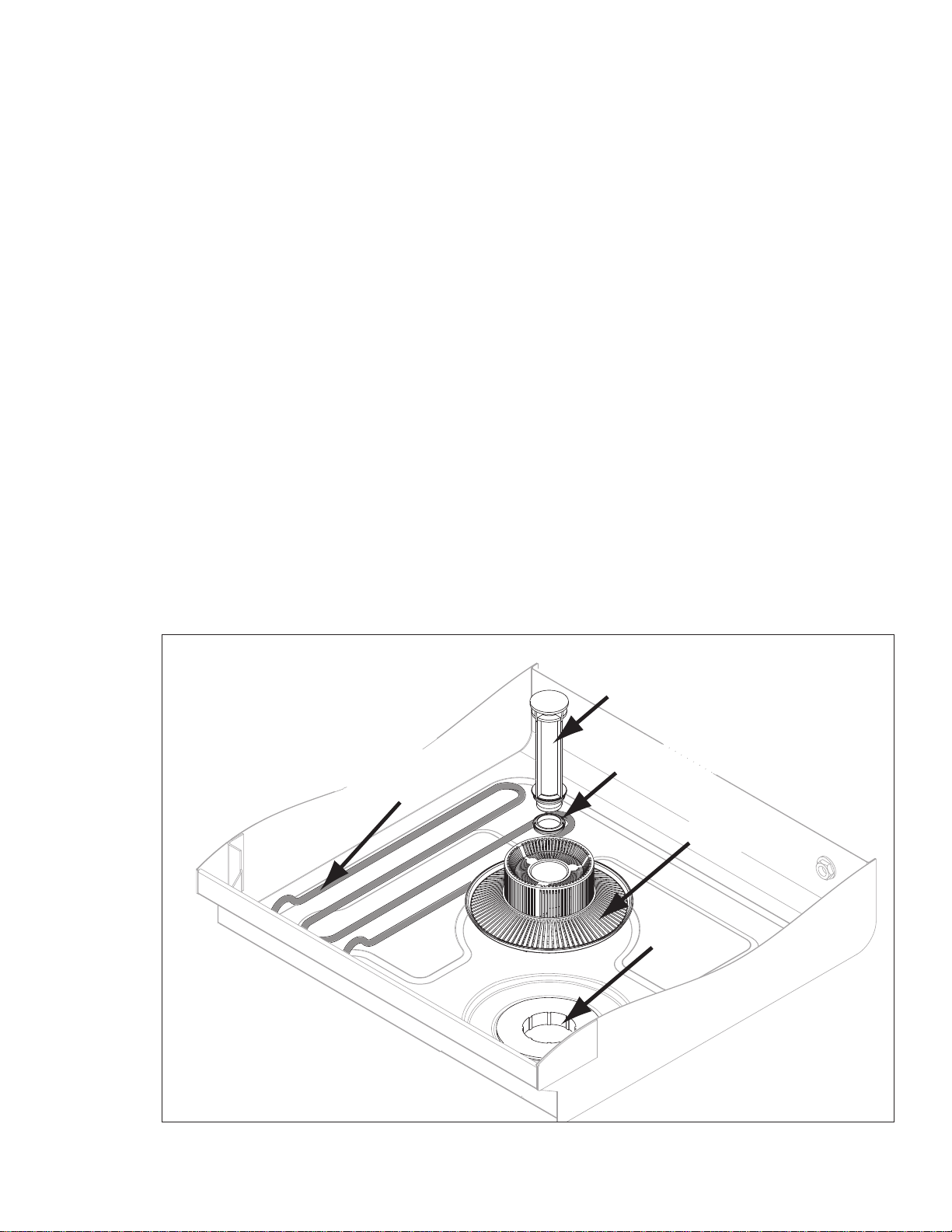
2. Open the door and remove the overow tube from the wash tank sump.
3. Inspect and clean the overow tube rubber seal
4. Close the door.
5. Push and hold the drain switch until all of the water has drained.
6. Remove the sump lter carefully to keep the soil or waste particles from falling into the sump.
7. Clean the sump lter by rinsing with clean water.
Be sure to back-ush the lter.
Do not strike the lter against solid objects.
8. Check the sump for foreign material and clean as required.
9. Replace sump ter and the overow tube.
10. Make sure that spray arms turn freely.
11. Check the chemical containers and rell as required.
12. Close the door and turn the ON/OFF switch to ON and return to normal operation mode.
Heating
Element
Overflow
Tube
Overflow
Seal
Sump
Filter
Sump
15
Page 22

Cleaning and Maintenance
Cleaning
At the End of the Day
1. Perform Steps 1-8 on the previous page.
2. Remove the upper and lower rinse and wash spray arms. The spray arms are interchangeable.
3. Unscrew the rinse arm pin (A). Remove the rinse arm assemblies
4. Clean the nal rinse arm nozzles using a small paper clip (B).
5. Remove the rinse arm end plugs (C) if necessary, and ush the rinse arm with clean water.
6. Re-install the rinse arm end plugs if they were removed.
7. Remove the wash spray arms and ush with clean water.
8. DO NOT USE STEEL WOOL TO CLEAN THE INTERIOR OF THE MACHINE.
9. Contact the chemical supplier for de-liming if required (see next page).
10. Wipe the interior and exterior of the machine with a soft cloth and a mild detergent.
DO NOT HOSE THE EXTERIOR OF THE MACHINE WITH WATER.
11. Reassemble the dishwasher and leave the door open to allow overnight drying.
Paper Clip
B
Rinse Arm Pin
A
End
Plug
C
Wash Spray arm
16
D
Page 23

Cleaning and Maintenance
De-liming
Minerals accumulate on the interior surfaces of the dishwasher. The deposits have a white haze
and, in cases of heavy accumulation, may appear as a granular solid. The generic name for mineral
deposits is lime. The removal of lime deposits is called de-liming. Your dishwasher should be delimed regularly; how often will depend on the mineral content of your water.
Inspect your machine interior for lime deposits. If deliming is required, a de-liming agent should be
used for best results in accordance with the chemical supplier's instructions.
Danger:
Death or serious injury may result when de-liming solution is mixed with sodium hypochlorite
(chlorine bleach) sanitizing agent. Mixing may cause hazardous gases to form.
De-liming solution and other acids must never be mixed with chlorine, iodine, bromine, or uorine.
Caution:
Skin contact with de-liming solutions can cause severe irritation and possible chemical burns.
Always wear protective clothing and googles when handling chemicals.
Attention:
Contact your chemical supplier for specic safety procedures and instructions for the use of
the de-liming solution supplied for the dishwasher.
De-liming solution or other chemicals are not supplied by the dishwasher manufacturer.
Overflow
Tube
Heating
Element
Overflow
Seal
Sump
Filter
Sump
17
Page 24

Cleaning and Maintenance
Maintenance
Follow the maintenance schedules below to keep the dishwasher operating most efciently.
Daily Maintenance
1. Check all of the wash arm and rinse arm spray jets and clean as necessary.
2. Make sure that the water supply is on and that the drain is not clogged.
3. Check the temperature gauges and/or displays to ensure that they are operating.
4. Make sure that dish racks are in good condition.
5. Check the chemical containers and rell as required.
6. Follow the cleaning procedures given above.
Weekly Maintenance
1. Perform Steps 1-5 in the Daily Maintenance.
2. Inspect water lines for leaks.
3. Check for water leaks underneath the dishwasher.
4. Make sure the exible water ll and drain hoses are not kinked.
5. Make sure that the dishwasher is level.
6. Clean accumulated lime deposits from the wash tank heating element.
7. Inspect the scrap screen and replace it if damaged.
8. Check the spray arms and replace or repair if damaged.
9. Clean the chemical dispenser pick-up tubing for the detergent and rinse-aid pumps.
To clean the pick-up tubing:
1. Remove the pick-up tubes from their containers.
2. Place each tube in a separate container of hot water.
3. Press and hold the PRIME button up in the DET position until water ows into the wash tank
compartment.
4. Press and hold the PRIME button down in the RINSE position until water ows into the wash
tank compartment.
5. Return the pick-up tubes to their containers.
6. Run 3 empty dishwasher cycles to ush any chemicals from the dishwasher wash
compartment.
7. Push and hold the chemical prime button to prime the chemical pumps.
18
Page 25

Troubleshooting
Troubleshooting
Follow the troubleshooting guide below in the event that your dishwasher does not operate as
expected. Perform the basic checks below before calling an authorized service agent:
1. Make sure that the main water supply is turned on.
2. Make sure that the main power is turned on.
3. Make sure that the exible water ll and drain hoses are not kinked.
Condition Cause Solution
Dishwasher will not run.
Low or no water.
Chemicals won’t feed into
dishwasher.
Poor wash results.
Door not closed.
Main power OFF.
Dishwasher OFF.
Main water supply off.
PRV setting incorrect
Solenoid strainer clogged.
Solenoid valve defective.
Chemical supply low.
Pick-up tube clogged
Supply tubing damaged.
Supply tubing kinked.
Wares incorrectly loaded.
in dishrack.
Clogged sump filter.
Clogged spray arms.
Detergent injector not
feeding.
Thermostat defective.
Close door completely.
Check breaker on panel.
Turn dishwasher ON.
Open supply valve.
Adjust the PRV setting
Clean strainer.
Contact Service Agent.
Refill chemical container.
Clean/replace tube.
Replace tubing.
Straighten tubing.
Reposition wares or
reduce amount of wares.
Clean sump filter.
Clean spray arms.
Replace squeeze tube or
clean tubing and pick-up
tube.
Contact Service Agent.
Dishwasher stays in
wash cycle.
Detergent motor defective.
Water temperature low.
Safe-T-Temp extends wash
mode to allow final rinse
water booster temperature
to reach 180˚F/82˚C.
Dishwasher is operating in
the Extended Wash Mode.
Contact Service Agent
Contact Service Agent
Contact Service Agent
because booster
thermostat is defective.
Press the Extended Wash
button 1 time. The Extended
Wash Indicator light will go
out, the wash cycle will
resume where it left off and
perform a final rinse cycle.
19
Page 26

Blank Page
This Page
Intentionally
Left Blank
20
Page 27

Service Replacement Parts
Service Replacement Parts
Illustrations Page
Wash Pump/Motor Assembly ................................................................................................................................ 22
Booster Assembly ................................................................................................................................................... 24
Electrical Panel and Timer Assembly ..................................................................................................................... 26
Control Panel Assembly ......................................................................................................................................... 28
Upper Final Rinse Piping Assembly ....................................................................................................................... 30
Wash and Rinse Spray Arm Assemblies ................................................................................................................ 32
Drain Pump and Lower Hose Assemblies .............................................................................................................. 34
Wash Tank Heater and Drain Assemblies .............................................................................................................. 36
Fill Solenoid Valve Assembly .................................................................................................................................. 38
Detergent Pump Assembly ..................................................................................................................................... 40
Rinse-aid Pump Assembly...................................................................................................................................... 42
Panel Assembly ...................................................................................................................................................... 44
Door Assembly ....................................................................................................................................................... 46
Dish racks, Line Strainer and Pressure Regulating Vavle (PRV) ........................................................................... 50
21
Page 28

Wash Pump/Motor Assembly
11
10
7
5
4
3
2
1
6
12
13
9
8
22
Page 29

Item Part Description Qty.
No. No.
Wash Pump/Motor Assembly
1 2103.01 SCREW, M4, PHIL, PAN HD. 9
2 2103.02 IMPELLER HOUSING COVER 1
3 2103.03 NUT, M6 (left-hand threads) 1
4 2103.04 WASHER, LOCK, 1/4" 1
5 2103.05 WASHER, PLAIN, M6 1
6 2103.06 IMPELLER 1
7 2103.07 SEAL 1
8 2103.30 GASKET, PUMP 1
9 2103.09 BACKPLATE, PUMP 1
10 2103.08 NUT, M4 9
11 2103.10 PUMP/MOTOR ASSEMBLY COMPLETE 1
220VAC/60/1
12 2103.37 COVER, REAR MOTOR FAN 1
13 2103.11 CAPACITOR 16μF 1
23
Page 30

Booster Assembly
From
Fill
Valve
To
Final
10
Rinse
21
6
11
6
19
18
20
6
10
6
13
12
7
6
11
6
10
6
14
9
8
15
5
17
16
4
3
2
1
24
Page 31

Item Part Description Qty.
No. No.
Booster Assembly
1 2103.12 HEATER, BOOSTER 4kW, 208V, 40°F RISE 1
(Does not include gasket)
1 2103.13 HEATER, BOOSTER 6kW, 208V, 70°F RISE 1
(Does not include gasket)
2 2103.14 GASKET, BOOSTER HEATER 1
3 2103.15 THERMOSTAT, CONTROL 195°F 1
(Prior to S/N W120631743)
4 2103.36 THERMOSTAT, CONTROL 110-195°F 1
(Beginning with S/N W120631743)
5 2103.16 BOLT, HEX FLANGE, 1/4-20 X 3/8" SST 1
6 2103.38 CLAMP, 29/32" x 1/2" WIDE SST 6
7 2103.22 HOSE, BOOSTER FILL 1
8 2103.19 THERMOSTAT, HI-LIMIT FIXED SNAP 240°F 1
9 2103.20 TANK, BOOSTER (All S/N's) 1
(Includes Item 14)
10 2103.22 HOSE, 1/2" ID A/R
11 2103.23 TEE, RINSE 2
12 2103.24 FITTING, BOOSTER THERMOMETER 1
13 0302.00 THERMOMETER, 2" DIAL, 7' CAPILLARY 1
14 2103.26 PLUG, 1/8" SST 1
15 2103.27 NUT, GRIP 6-32 W/NYLON INSERT 2
16 2103.28 FITTING, BOOSTER THERMOSTAT 1
(Use with Item 3, Prior to S/N W120631743))
17 2103.61 FITTING, BOOSTER THERMOSTAT 1
(Use with Item 3, Beginning with S/N W120631743))
18 2103.62 FITTING, COMP. 1/4" OD X 1/8" MPT ELL J 1
19 13604.10 BUSHING, REDUCER 1/2" X 1/8" 1
20 2103.74 TUBING, 1/4" NATURAL 2 FT.
21 40014.00 COUPLER, 1/2" HOSE X 1/2" FNPT BRASS 1
25
Page 32

Electrical Panel and Timer Assembly
11
3
2
1
6
4
WASH
RINSE
TEMPERATURE
5
BOOSTER
8
ON
OFF
FILL
10
9
7
11
12
15
11
13
Item 10, Timer Assembly
includes: Items 12 and 13
20
19
18
11
26
16
11
14
17
11
Page 33

Item Part Description Qty.
No. No.
Electrical Panel and Timer Assembly
1 2103.29 THERMOSTAT, WASH TANK 1
2 2103.15 THERMOSTAT, CONTROL 195°F 1
(Prior to S/N W120631743)
3 2103.36 THERMOSTAT, CONTROL 110-195°F 1
(Beginning with S/N W120631743)
4 2103.63 BRACKET, THERMOSTAT 1
(Use with Item 3 only)
5 2103.31 SWITCH, 3-POSITION, TOGGLE 1
6 2103.34 SCREW, NIBS RH 6-32 X 3/16" PHIL. SST 4
7 2103.32 LABEL, ON/OFF/BOOSTER FILL 1
8 2103.33 LABEL, WASH-RINSE TEMPERATURE 1
9 2103.35 BUSHING, 1" ID 2
10 00408.60 ASSEMBLY, TIMER (Includes Items 12, 13) 7
11 2103.59 SCREW, TRUSS SLOT, 8-32 X 1/4" SST 10
12 0411.00 SWITCH, TIMER 7
13 00501.00 MOTOR, TIMER 1
14* 2103.43* KIT, FILL/DRAIN TIMER (All S/N's) 1
15 2103.45 SCREW, RH 4-40 X 3/16" SLOTTED SST 4
16 2103.40 RELAY, 15 AMP, 120VAC COIL 1
17 2103.46 RELAY, 120VAC, 2PDT 1
18 2103.47 BLOCK, TERMINAL 1
19 2103.48 CONTACTOR, 25/40A, 3P, 120V COIL 1
20 2103.49 PANEL, CONTROL 1
* Note: See Kit Installation Instructions at the end of this manual
27
Page 34

Control Panel Assembly
11
1
12
2
3
4
5
6
8
7
9
5
8
10
11
12
5
4
7
28
Page 35

Item Part Description Qty.
No. No.
Control Panel Assembly
1 2103.42 PANEL, FACIA, UC65e 1
2 2103.44 LABEL, FACIA, UC65e 1
3 2103.50 SWITCH, ON-OFF 1
4 2103.51 CONTACT, MOMENTARY, N.O. 2
5 2103.52 HOUSING, SWITCH 3
6 2103.53 BUTTON, SWITCH (GREEN) 1
7 2103.54 BUTTON, SWITCH (GREY) 2
8 2103.55 LIGHT, INDICATOR LED, 125VAC (GREEN) 2
9 2103.56 CONTACT, SWITCH (EXTENDED WASH) 1
10 2103.57 SWITCH, MOMENTARY (PRIME) 1
11 2103.58 GASKET, STEAM 2
12 2103.59 SCREW, TRUSS SLOT., 8-32 X 1/4" SST 2
29
Page 36

UpperFinalRinsePipingAssembly
3
2
4
15
1
4
12
5
13
6
7
11
2
1
10
8
9
14
1
2
30
Page 37

Item Part Description Qty.
No. No.
UpperFinalRinsePipingAssembly
1 2103.60 HOSE, RUBBER 1/2ID X .84OD AR
2 2103.21 CLAMP, SS GEAR-MIN. 5/16-MAX.7/8 6
3 2103.62 FITT COMP 1/4OD X 1/8MPT ELL J 1
(Prior to S/N W120631743)
4 2103.26 PLUG, 1/8 HEX COUNTERSUNK 2
(Beginning with S/N W120631743)
5 2103.64 MANIFOLD, RINSE 1
6 2103.65 INJECTOR FITTING 1
7 2103.66 TUBING, 1/8OD X 1/16 ID AR
8 2103.67 NUT, HEX SS 1/4-20 2
9 2103.04 WASHER, SPLIT LOCK 1/4i 304SS 2
10 2103.69 BRACKET, VACUUM BREAKER 1
11 2103.70 NUT, LOCK 1/2" NICKEL PLATED 1
12 2103.71 VACUUM BREAKER, 1/2" BRASS 1
13 2103.72 REPAIR KIT, VACUUM BREAKER 1/2" 1
14 2103.73 COUPLER 1/2 MPT X 1/2" HOSE 1
15 2103.74 TUBING, 1/4" NATURAL AR
(Prior to S/N W120631743)
31
Page 38

Wash and Rinse Spray Arm Assemblies
2
1
12
18
5
4
3
9
23
6
7
13
14
21
8
20
21
21
19
21
20
12
17
10
15
16
22
19
18
23
8
9
6
32
11
Page 39

Item Part Description Qty.
No. No.
Wash and Rinse Spray Arm Assemblies
1 2103.75 WASHER, 17/64 id X 9/16" OD SST 4
2 2103.76 NUT, HEX 1/40-20 NYLON INSERT SST 4
3 2103.77 HUB, UPPER WASH ARM 1
4 2103.78 WASHER, PACKING 1
5 2103.79 SCREW, RETAINING 1
6 2103.80 CLAMP, HOSE GEAR 1-1/2" SST 2
7 2103.81 HOSE, UPPER WASH ARM 1
8* 2103.82 BEARING ASSEMBLY 2
9 2103.83 O-RING, 2-1/8" OD X 1-3/4" ID X 3/16" 2
10 2103.84 HUB, LOWER WASH ARM 1
11 2103.85 MANIFOLD, LOWER FWR 1
12 2103.86 WASH ARM ASSEMBLY (Includes Item 8) 2
13 2103.88 WASHER, NYLITE 4
14 2103.89 BOLT, 1/4-20 X 1" SST 4
15 2103.90 SHAFT, LOWER 1
16 2103.91 O-RING 1
17 2103.92 HUB, RINSE ARM, MOLDED 2
18 2103.93 SCREW, TRUSS SLOTTED 8-32 X 1/4" SST 4
19 2103.94 ARM, RIGHT-HAND RINSE (7 JETS) 2
20 2103.95 ARM, LEFT-HAND RINSE (8 JETS) 2
21 2103.96 CAP, RINSE ARM, 5/16-24 4
22 2103.97 SPINDLE, RINSE ARM 2
23 2103.98 SPACER, NUT 2
--- 2103.99 RINSE ARM ASSEMBLY (Includes Items 18-23) 2
* Note:
The bearing assembly, P/N 2103.82 includes 2 bearings, 1 locknut, and 1 wash arm hub.
The bearings, locknut and hub are not available as separate service replacement parts.
33
Page 40

Drain Pump and Lower Hose Assembly
17
5
18
18
16
To upper washarm hub
From Final Rinse Manifold
4
3
1
2
12
11
5
5
7
8
9
10
2
6
13
12
2
15
14
19
34
Page 41

Item Part Description Qty.
No. No.
Drain Pump and Lower Hose Assembly
1 02104.00 HOSE, FILL 1/2" X 7' C/W 3/4" FNPS 1
2 2103.16 BOLT, HEX FLANGE, 1/4-20 X 3/8" SST 6
3 2103.18 HOSE, BOOSTER FILL, 1/2" X 1' 1
4 2103.17 CLAMP, HOSE GEAR-TYPE 5/16" 1
5 2104.04 CLAMP, HOSE GEAR-TYPE, 1", SST 2
6 2104.05 HOSE, DRAIN PUMP SUCTION 1
7 2104.06 BRACKET, DRAIN PUMP 1
8 2104.07 PUMP, DRAIN 115VAC 1
9 2104.08 CLAMP, HOSE GEAR-TYPE SST 1
10 798.00 HOSE, BRAIDED 20" 1
11 2104.09 BRACKET, WASH PUMP 1
12 2104.10 CLAMP, HOSE GEAR-TYPE 1-13/16"- 2-3/4" MAX SST 2
13 2104.11 HOSE, SUCTION WASH PUMP 1
14 2103.80 CLAMP, HOSE GEAR-TYPE, 1-1/2", SST 2
15 2104.13 HOSE, DISCHARGE WASH PUMP 1
16 2103.81 HOSE, UPPER WASH ARM 1
17 2103.22 HOSE, RUBBER 1/2" 1D X .84" OD A/R
18 2103.21 CLAMP, HOSE GEAR-TYPE 2
19* 2103.68 COUPLER, 3/4" MPT X 3/4" HOSE BARB 1
* NOTE:
ITEM 19 IS STRAPPED TO THE DRAIN HOSE AS A SEPARATE PART FOR THE
PLUMBING INSTALLER TO USE DURING INSTALLATION.
35
Page 42

Wash Tank Heater and Drain Assembly
1
27
26
25
2
23
22
24
21
3
4
5
6
7
8
2
11
5
20
3
9
13
3
4
10
4
12
13
14
15
16
17
19
36
18
Page 43

Item Part Description Qty.
No. No.
Wash Tank Heater and Drain Assembly
1 2104.17 GASKET, DOOR 1
2 2104.18 HEATER, WASH TANK, 2KW, 240VAC 1
3 968.00 WASHER, SPLIT LOCK 1/4" SST 4
4 2103.67 NUT, HEX 1/4-20 SST 4
5 2104.21 O-RING 2
6 2104.22 ADAPTER, THERMOSTAT 1
7 2103.28 BUSHING, THERMOSTAT 1
8 2103.29 THERMOSTAT, WASH TANK 1
9 2104.25 ADAPTER, THERMOMETER 1
10 2103.25 THERMOMETER, 2" DIAL C/W 7' CAPILLARY 1
11 2103.70 NUT, LOCK 1/2" NICKLE-PLATED 2
12 2104.28 THERMOSTAT, FIXED, SNAP 212°F 1
13 2103.27 NUT, GRIP 6-32 W/NYLON INSERT 4
14 2103.30 SCREW, 4-40 X 1/2" SST 2
15 43019.00 SWITCH, DOOR 15 AMP 1
16 2104.32 BRACKET, SWITCH 1
17 2104.33 PLATE, SWITCH NUT 1
18 2104.34 ELBOW, PUMP SUCTION 1
19 2104.35 GASKET, PUMP SUCTION 1
20 2104.36 FLANGE, PUMP SUCTION 1
21 2104.37 HOSE, 1/4" ID X 3/8" OD A/R
22 2104.38 ELBOW, 3/8" TUBE X 1/4" NPT 1
23 2104.39 GASKET, 1/4" FIBER 1
24 2104.40 LOCKNUT, 1/4" PLASTIC 1
25 2104.41 FILTER, SUMP 1
26 2104.42 SEAL, OVERFLOW TUBE 1
27 2104.43 TUBE, OVERFLOW 1
37
Page 44

FillSolenoidValveAssembly
1
1a
4
3
2
6
5
38
Page 45

Item Part Description Qty.
No. No.
FillSolenoidValveAssembly
1 03604.00 VALVE, SOLENOID, DEMA 1/2" 115VAC/60/1 1
(Includes Items 1a)
1a 03604.30 KIT, REPAIR SOLENOID VALVE, DEMA 1/2" A/R
2 03604.50 FITTING, FLOW DISC, DEMA 1
3 03604.10 WASHER, FLOW, DEMA 1
4 2103.73 FITTING, BARB HOSE 1
5 2104.45 BRACKET, VALVE, UC65E 1
6 2103.16 BOLT, HEX FLANGE 1/4-20 X 3/8" SST 2
39
Page 46

Detergent Pump Assembly
13
12
11
13
10a
10
6
8
7
9
5
14
5
9d
9c
9b
4
9a
3
40
2
1
Page 47

Item Part Description Qty.
No. No.
Detergent Pump Assembly
1 2104.47 STRAINER 1
2 2104.48 TUBE,1/2IDX11-7/8LG. STIFFENER 1
3 2104.49 LABEL, DETERGENT 1
4 2104.37 HOSE, 1/4ID X 3/8OD PVC A/R
5 2104.51 TIE, NYLON 4" 4
6 2104.52 ELBOW, 1/4 HOSE BARB 1
6 00435.10 TUBE, SQUEEZE PUMP 1
7 00911.00 SCREW 4
8 00418.00 COVER, PUMP 1
9 00419.00 ASSEMBLY, ROLLER 1
9a 00423.00 ROLLER 2
9b 00422.00 PIN, ROLL 1
9c 00424.00 BEARING, CARRIAGE 1
9d 00933.00 SCREW, SET 1
10 00919.00 SCREW 2
10a 00918.00 SCREW, FILISTER HD. 1
11 00417.00 BLOCK, PUMP 1
12 00416.10 MOTOR, PUMP 115VAC 1
13 00448.00 CONNECTOR, PUMP MOTOR 2
----- 00415.00 ASSEMBLY, PERI-PUMP COMPLETE 1
(Includes Items 6-13)
41
Page 48

Rinse-Aid Pump Assembly
13
12
11
10a
6
8
9
10
13
5
7
9d
4
9c
9b
3
9a
42
2
5
14
1
Page 49

Item Part Description Qty.
No. No.
Rinse-Aid Pump Assembly
1 2104.47 STRAINER 1
2 2104.48 TUBE,1/2ID X 11-7/8LG. STIFFENER 1
3 2104.49 LABEL, RINSE AID 1
4 2104.50 TUBING, 1/8" OD X 1/16 ID" AR
5 2104.51 TIE, CABLE 4" 4
6 00836.00 TUBE, SQUEEZE PUMP 1
7 00911.00 SCREW 4
8 00418.00 COVER, PUMP 1
9 00419.00 ASSEMBLY, ROLLER 1
9a 00423.00 ROLLER 2
9b 00422.00 PIN, ROLL 1
9c 00424.00 BEARING, CARRIAGE 1
9d 00935.00 SCREW, SET 1
10 00919.00 SCREW 2
10a 00918.00 SCREW, FILISTER HEAD 1
11 00417.10 BLOCK, PUMP 1
12 00416.00 MOTOR, PUMP 115VAC 1
13 00448.00 CONNECTOR, PUMP MOTOR 2
14 2104.58 TUBE, PUMP, 1/8" ID X 2" LG. 1
----- 00815.20 ASSEMBLY, PERI-PUMP COMPLETE 1
(Includes Items 6-13)
43
43
Page 50

Panel Assembly
14
14
11
14
12
13
12
1
3
2
4
5
10
9
9
44
6
8
9
7
7
Page 51

Item Part Description Qty.
No. No.
Panel Assembly
1 2103.62 FITT COMP 1/4" OD X 1/8 MPT ELL J 1
2 2104.60 ADAPTOR, 1/8" NPT X 1/4" TUBE 1
3 2103.74 TUBING, 1/4" NATURAL A/R
4 2104.62 LABEL, GUAGE 1
5 2104.63 GAUGE, PRESSURE 0-60PSI 1
6 2103.25 THERMOMETER, 2" DIAL, 7' CAPILLARY 2
7 2104.65 SCREW, 1/4-20 X 5/8" TRUSS HD. PHIL. SST 2
8 2104.66 PANEL, FRONT UC65e 1
9 2104.67 FOOT, ADJUSTING 4
10 2104.68 NUT, KEPS, 10-32 SST 1
11 2104.69 WRAP, OUTER PANEL 1
12 2104.70 CLAMP, DOUBLE CONDUIT 3
14 2103.39 SCREW TRUSS SLOT SS 10-32X3/8 4
13 2104.72 PANEL, REAR 1
45
Page 52

Door Assembly
1
5
4
3
2
3
2
6
7
46
Page 53

Item Part Description Qty.
No. No.
Door Assembly
1 2104.73 DOOR WELDED ASSY 1
2 2104.76 ARM, DOOR SPRING 2
3 2104.77 SPRING, DOOR 2
4 2104.78 ACTUATOR, DOOR SWITCH 1
5 2103.41 SCREW, 8-32 X 3/16" PHIL. SST 2
6 2104.88 SEAL, DOOR DRIP, RH 1
7 2104.87 SEAL, DOOR DRIP, LH 1
47
Page 54

DishRacks,LineStrainer,PRV
1
2
4
48
3
48
Page 55

Item Part Description Qty.
No. No.
DishRacks,LineStrainer,PRV
1 2104.80 DISH RACK, FLAT-BOTTOM AR
2 2104.81 DISH RACK, PEG AR
3 2104.82 STRAINER, LINE 1/2" BRONZE (OPTIONAL) 1
4 2104.83 VALVE, PRESSURE REGULATING (PRV) 1
49
Page 56

ElectricalSchematic,TimerChart,Fill/DrainTimer
Electrical Schematic,Timer Chart
Illustrations Page
Model UC65e Electrical Schematic ..................................................................................... 51
Timer Chart ........................................................................................................................... 52
50
Page 57

Model UC65e - Electrical Schematic
TO CUSTOMERS DISCONNECT SWITCH
PER LOCAL ELECTRICAL CODE
115-208/230V/1PH 60HZ
1
1
TT
TS
3
4
WHTR
5
PS
1L1
1L2
POL
10
25
1
1
DOOR
SWITCH
6
EXT. WASH SWITCH
START SWITCH
HC1
DRAIN
SWITCH
11
CPS
1
19
9
BFS
L1
L2
7
8
N
EWL
13
SR1
26
SR1-2
12
6
2
3
HOMING
CAM
1
3
2
1
3
2
1
2
13
33
EXT. WASH
CAM
WASH PUMP
DRAIN PUMP
FILL/RINSE
15
2
SAFETY
TEMP
CAM
16
17
19
7
8
2
DETERGENT
9
2
R/A
27
6
TIMER
SR
TM
CL
WPR
DP
RV
DEP
RAP
NL2L1
GND
HC1
1H2
1H1
BOOSTER HEAT
208/230 VAC
23
WPR
DIAGRAM STATE
END OF CYCLE
POWER-OFF
DOOR-OPENED
MINIMUM CIRCUIT AMPACITY
30 AMPS
MAXIMUM OVERCURRENT
PROTECTION 30 AMPS
BFS
BOOSTER FILL SWITCH
BS
BOOSTER SAFETY THERMOSTAT
BT
BOOSTER THERMOSTAT
CL
CYCLE LIGHT
CPS
CHEMICAL PRIME SWITCH
DEP
DETERGENT PUMP
DP
DRAIN PUMP
EWL
EXTENDED WASH LIGHT
EWS
EXTENDED WASH SWITCH
GND
GROUND
HC1
BOOSTER CONTACTOR
1HTR
BOOSTER HEATER
POL
POWER ON LIGHT
PS
POWER ON SWITCH
RAP
RINSE AID PUMP
RV
RINSE VALVE
SR
START RELAY
TM
TIMER MOTOR
TS
TANK HEAT SAFETY THERMOSTAT
TT
TANK HEAT THERMOSTAT
WHTR
WASH TANK HEATER
WPR
WASH PUMP RELAY
WP
1HTR
4 kW
1L1
1
10
DOOR
SW
RINSE
HOT
FILL TIMER MODULE
SW. PWR.
DRAIN
19
N
Model UC 65e
HIGH TEMP UNDERCOUNTER
DATE
25-FEB-09
NUMBER/REV
UC65e/0512867/REVA
10
1
BT
BS
21
22
HC1
N
51
Page 58

TIMING CHART
05CTIME
Timer Chart - Model UC65e
120
110
100
90
80
70
60
50
DRAWING NO.
UC65e
40
30
20
10
6
0
TIME (SEC.)
1 HOMING CAM
3 DRAIN PUMP
2 WASH PUMP
4 RINSE VALVE
5 DET PUMP
6 RINSE AID PUMP
7 EXTENDED WASH
8 SAFE-T-TEMP
CMA Dishmachines
52
Page 59

Service Parts Installation Instructions
Service Parts Installation Instructions
Booster Thermostat P/N 2103.36 ...............................................................................54
Pressure Gauge Piping Change .................................................................................56
Fill/DrainTimerConversionP/N2103.43 ...................................................................58
Fill/DrainTimer-TheoryofOperation ........................................................................62
53
Page 60

Service Parts Installation - Booster Thermostat P/N 2103.36
Beginning with S/N W120631743, the booster control thermostat, P/N 2103.36 replaced the
existing thermostat, 2103.15. For machines built prior to S/N W120631743, the old thermostat
P/N 203.15 must be used unless a new booster tank, P/N 2103.20, is installed at the same time.
Refer to the photographs below and on the next page for installation instructions.
54
Page 61

Service Parts Installation - Booster Thermostat P/N 2103.36
55
Page 62

Service Parts Installation - Pressure Gauge Piping Change
Beginning with S/N W120631743, the pressure gauge tubing has been relocated
from the top right rear corner of the machine to the booster located on the base
of the machine. This change improves the operation of the nal rinse pressure gauge.
Refer to the illustrations below and on the next page for installation instructions.
Remove this connector.
Move this hose
to front of
machine near
pressure gauge.
Install this plug
where the connector
was removed.
Parts list is located on
pages 30-31.
56
Page 63

Service Parts Installation - Pressure Gauge Pipiing Change
New parts needed for
the conversion.
From
Fill
Valve
Parts list on pages 24-25.
Relocated from
rear of the machine.
57
Page 64

ServicePartsInstallation-Fill/DrainTImerConversion-P/N2103.43
Fill/DrainTimerConversion-P/N2103.43
All S/N's have a new ll/drain timer, P/N 2103.43. This new timer is slightly
larger than previous timers but it still mounts in the same location as previous timers.
The only function of the ll/drain timer is to ll the machine at the beginning of the day and to drain the
machine at the end of the day. Normal wash and nal rinse cycles are controlled by the mechanical
cam timer assembly.
Refer to the illustrations below and on the following pages for installation instructions.
58
Page 65

ServicePartsInstallation-Fill/DrainTimerConversion-P/N2103.43
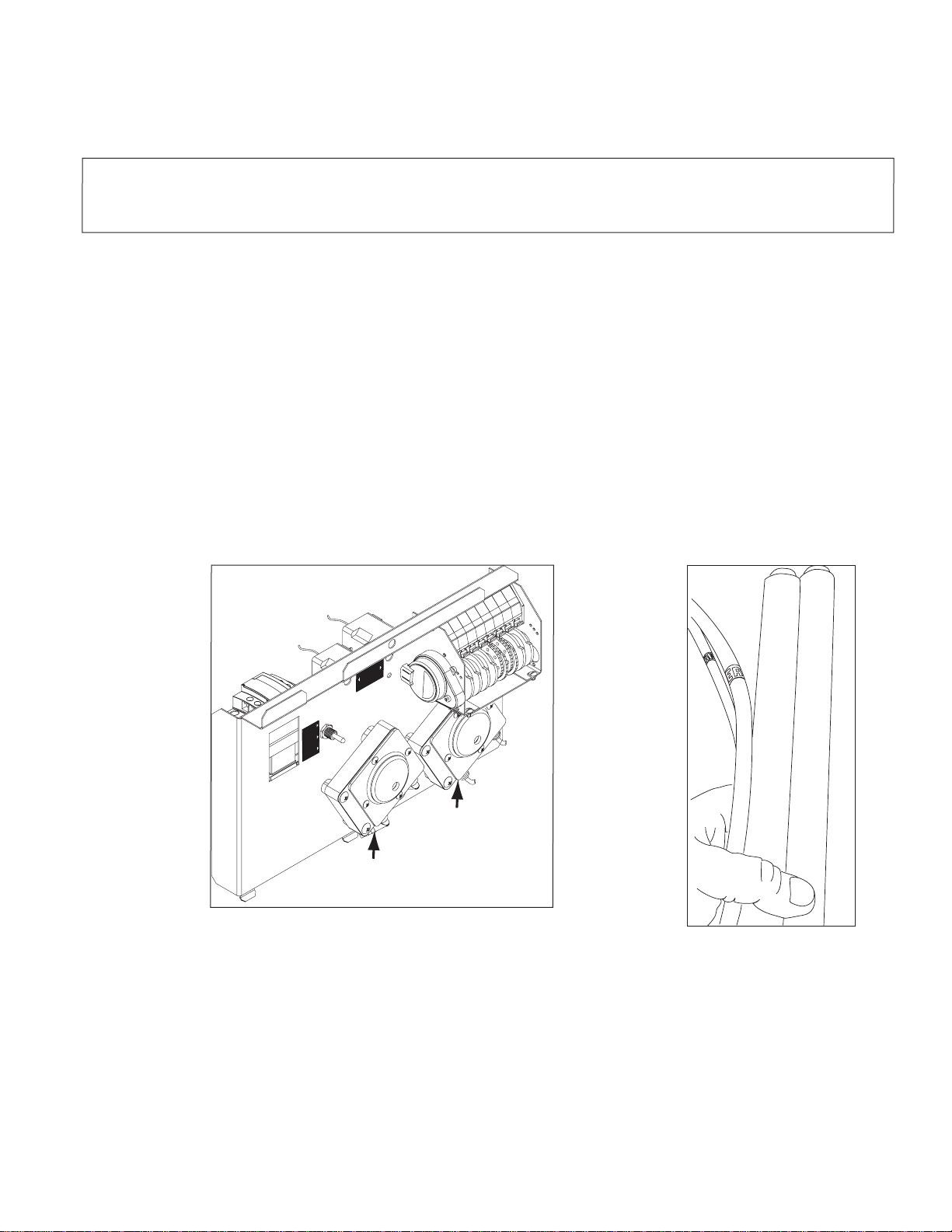
If your machine has the Cam Timer
with black cams, then the board
mounting screws can be accessed
without removing the timer drive motor.
If your machine has white and gray
timer cams (A), then it may be
necessary to remove the timer drive
motor to access one of the ll/drain
timer mounting screws (B).
To remove the timer drive
motor (A), remove the two
phillips screws and drop the
timer drive motor out of the way.
With the drive motor removed,
you can access the ll/drain
timer mounting screws (C) and
remove them.
__continued on next page
59
Page 66

ServicePartsInstallation-Fill/DrainTImerConversion-P/N2103.43
Fill/DrainTimerConversion-P/N2103.43
continuedfrompreviouspage
60
Page 67

ServicePartsInstallation-Fill/DrainTimerConversion-P/N2103.43
Connect the wires as shown on
the previous page and reinstall
the mounting screws. Reinstall
the timer motor.
Fill/Drain Timer Conversion - P/N 2103.43
The new board shown with wires
connected and mounting screws
installed. The installation is
complete.
61
Page 68

Fill/DrainTimer-TheoryofOperation
Fill/DrainTimerBoard-TheoryofOperation
LED's 1, 2, and 3 are illuminated
during a normal wash/rinse cycle.
The new ll/drain timer board has built-in diagnostics.
LED's (1, 2, 3, and 4) illuminate under the following conditions:
a) LED 1 illuminates when power from circuit breaker is ON and booster/ll
switch (service switch) is ON.
b) LED 2 illuminates when machine ON/OFF switch is ON and circuit breaker in ON.
c) LED 3 (Door switch LED) illuminates when door is closed, machine ON/OFF switch is
ON and circuit breaker in ON. LED 3 goes out when door is open.
d) LED 4 only illuminates momentarily when the drain switch is pressed and the machine
ON/OFF switch is OFF.
e) LED 5 (Drain LED) illuminates when the Power from the circuit breaker is ON, the
machine ON/OFF switch is OFF, and the momentary drain switch has been pressed to
start the 50 second drain cycle. The door can be opened during the drain cycle,
closing the door resumes the drain cycle where it left off.
NOTE: LED 5 will illuminate during the ll cycle because the drain pump also runs during
the ll cycle.
f) LED 6 (Fill Valve LED) illuminates when the circuit breaker is ON, the machine
ON/OFF switch is ON (3 second delay), and the door is closed.
NOTE: LED 5 will illuminate during the ll cycle because the drain pump also runs during
every 70 second ll cycle.
62
 Loading...