

Page 1

OPERATING, MAINTENANCE
& PARTS MANUAL
ELECTRIC CHAIN HOIST
SHOPSTAR
SLC SERIES
SHOPHOIST
SLM SERIES
Before installing hoist, fill in the information below.
Model Number
Serial No.
Purchase Date
Follow all instructions and warnings for inspecting,
maintaining and operating this hoist.
The use of any hoist presents some risk of personal injury
or property damage. That risk is greatly increased if proper
instructions and warnings are not followed. Before using
this hoist, each operator should become thoroughly familiar
with all warnings, instructions and recommendations in this
manual. Retain this manual for future reference and use.
Forward this manual to the hoist operator. Failure to operate
equipment as directed in manual may cause injury.
Columbus McKinnon Corporation
205 Crosspoint Parkway
Getzville, NY 14068
P/N 192047138 Rev AA November 2017
Page 2

CM HOIST PARTS AND SERVICES ARE AVAILABLE IN THE UNITED STATES AND IN CANADA
As a CM Hoist and Trolley user you are assured of reliable repair and parts services through a network of Master Parts Depots and Service
Centers that are strategically located in the United States and Canada. These facilities have been selected on the basis of their demonstrated
ability to handle all parts and repair requirements promptly and efciently. To quickly obtain the name of the Master Parts Depot or Service
Center located nearest you, call (800) 888-0985. Fax: (716) 689-5644.
LAS PIEZAS Y REPARACIONES DE LOS POLIPASTOS DE CM
ESTÁN ASEGURADAS EN ESTADOS UNIDOS Y CANADÁ
Como usuario de un polipasto y carro de CM le aseguramos cualquier reparación o la disponibilidad de cualquier pieza de repuesto a
través de una red de almacenes de piezas de repuesto y centros de servicio situados estratégicamente en Estados Unidos y Canadá. Estas
instalaciones se han seleccionado en base a su capacidad demostrada en la reparación de equipos y suminstro de piezas de repuesto de
forma rápida y ecaz. Para obtener la dirección del almacén de piezas de repuesto o del centro de servicio más cercano, llame al teléfono
(800) 888-0985. Fax: (716) 689-5644 (sólo en Estados Unidos y Canadá).
LE SERVICE DE RÉPARATION ET DE PIÈCES POUR PALANS CM
EST DISPONIBLE AUX ÉTATS-UNIS ET AU CANADA
Soyez assurés qu'en temps d'utilisateur de palan et treuil CM, d'un service de réparation et de pièces able par l'entremise d'un réseau de
Centres de service et de Dépôts de pièces maîtresses qui sont stratégiquement situés aux États-Unis et au Canada. Ces établissements ont
été sélectionnés sur une base de leur habileté démontrée à s'occuper promptement et efcacement des besoins de réparation de pièces.
Appelez le (800) 888-0985, Fax: (716) 689-5644 pour obtenir rapidement le nom du dépôt de pièces maîtresses ou du centre de service situé
le plus près.
2
P/N 192047138 Rev AA November 2017
Page 3
Improper operation of a hoist can create a potentially
hazardous situation which, if not avoided, could result in
death or serious injury. To avoid such a potentially hazardous
situation, THE OPERATOR SHALL:
a. NOT operate a damaged, malfunctioning or unusually
performing hoist.
b. NOT operate the hoist until you have thoroughly read and
understood this Operating, Maintenance and Parts Manual.
c. NOT operate a hoist which has been modied.
d. NOT lift more than rated load for the hoist.
e. NOT use hoist with twisted, kinked, damaged, or worn load
chain.
f. NOT use the hoist to lift, support, or transport people.
g. NOT lift loads over people.
h. NOT operate a hoist unless all persons are and remain clear
of the supported load.
i. NOT operate unless load is centered under hoist.
j. NOT attempt to lengthen the load chain or repair damaged
load chain.
k. Protect the hoist’s load chain from weld splatter or other
damaging contaminants.
l. NOT operate hoist when it is restricted from forming a
straight line from hook to hook in the direction of loading.
m. NOT use load chain as a sling, or wrap chain around load.
n. NOT apply the load to the tip of the hook or to the hook
latch.
o. NOT apply the load unless load chain is properly seated in
the chain wheel(s) or sprocket(s).
p. NOT apply load if bearing prevents equal loading on all load
supporting chains.
q. NOT operate beyond the limits of the load chain travel.
r. NOT leave load supported by the hoist unattended unless
specic precautions have been taken.
s. NOT allow the load chain or hook to be used as an electrical
or welding ground.
t. NOT allow the load chain or hook to be touched by a live
welding electrode.
u. NOT remove or obscure the warnings on the hoist.
v. NOT operate a hoist on which the safety placards or decals
are missing or illegible.
w. NOT operate a hoist unless it has been securely attached to
a suitable support.
x. NOT operate a hoist unless load slings or other approved
single attachments are properly sized and seated in the
hook saddle.
y. Take up slack carefully - make sure load is balanced and
load holding action is secure before continuing.
z. Shut down a hoist that malfunctions or performs unusually
and report such malfunction.
aa. Make sure hoist limit switches function properly.
ab. Warn personnel of an approaching load.
Improper operation of a hoist can create a potentially
hazardous situation which, if not avoided, could result
in minor or moderate injury. To avoid such a potentially
hazardous situation, THE OPERATOR SHALL:
a. Maintain rm footing or be otherwise secured
when operating the hoist.
b. Check brake function by tensioning the hoist prior
to each lift operation.
c. Use hook latches. Latches are to retain slings, chains, etc.
under slack conditions only.
d. Make sure the hook latches are closed and not supporting
any parts of the load.
e. Make sure the load is free to move and will clear
all obstructions.
f. Avoid swinging the load or hook.
g. Make sure hook travel is in the same direction as shown
on the controls.
h. Inspect the hoist regularly, replace damaged or worn parts,
and keep appropriate records of maintenance.
i. Use factory parts when repairing the unit.
j. Lubricate load chain per hoist manufacturer’s
recommendations.
k. NOT use the hoist’s overload limiting clutch to measure
load.
l. NOT use limit switches as routine operating stops.
They are emergency devices only.
m. NOT allow your attention to be diverted from operating
the hoist.
n. NOT allow the hoist to be subjected to sharp contact with
other hoists, structures, or objects through misuse.
o. NOT adjust or repair the hoist unless qualied to perform
such adjustments or repairs.
SAFETY PRECAUTIONS
Each Shopstar Electric Hoist is built in accordance with the
specications contained herein and at the time of manufacture
complied with our interpretation of applicable sections of the National
Electrical Code (ANSI/NFPA 70). Installers are required to provide
current overload protection and grounding in keeping with the code.
Check each installation for compliance with the applicable sections of
the code as well as the National, State and Local Codes that may apply
to the installation. In addition, safety code requirements associated
with the operation of a hoist in the inverted (theatrical) position (chain
port up), as with any mechanical equipment, vary depending upon
locality. Therefore, before installing the hoist, the user should consult
his insurance company and/or local authority to see if a deviation is
required to permit the use of the hoist in this particular application.
The safety laws for elevators, lifting of people and for dumbwaiters
specify construction details that are not incorporated into
the hoists. For such applications, refer to the requirements of
applicable state and local codes, and the American National Safety
Code for elevators, dumbwaiters, escalators and moving walks
(ASME A17.1). We cannot be responsible for applications other
than those for which the equipment is intended.
* Copies of this standard can be obtained from ASME Order Department,
22 Law Drive, PO Box 2300, Faireld, NJ 07007- 2300, U.S.A.,
www.asme.org, 800-843-2763.
THIS SYMBOL POINTS OUT IMPORTANT SAFETY
INSTRUCTIONS WHICH IF NOT FOLLOWED COULD
ENDANGER THE PERSONAL SAFETY AND/OR PROPERTY
OF YOURSELF AND OTHERS. READ AND FOLLOW ALL
INSTRUCTIONS IN THIS MANUAL AND ANY PROVIDED
WITH THE EQUIPMENT BEFORE ATTEMPTING TO
OPERATE YOUR SHOPSTAR HOIST.
3
P/N 192047138 Rev AA November 2017
Page 4
HOIST SAFETY IS UP TO YOU...
DO NOT LIFT MORE THAN RATED LOAD.
CHOOSE THE RIGHT HOIST FOR THE JOB...
Choose a hoist with the capacity for
the job. Know the capacities of your
hoists and the weight of your loads.
Then match them.
The application, the size and type
of load, the attachments to be used
and the period of use must also be
taken into consideration in selecting
the right hoist for the job.
Remember, the hoist was
designed to ease our burden and
carelessness not only endangers the
operator, but in many cases, a valuable load.
DO NOT OPERATE DAMAGED OR MALFUNCTIONING HOIST.
DO NOT OPERATE WITH TWISTED, KINKED, OR DAMAGED CHAIN.
INSPECT
All hoists should be visually inspected
before use, in addition to regular, periodic
maintenance inspections.
Inspect hoists for operations warning notices
and legibility.
Deciencies should be noted and brought to the attention of
supervisors. Be sure defective hoists are tagged and taken out
of service until repairs are made.
Under no circumstances should you operate a malfunctioning hoist.
Check for gouged, twisted,
distorted links and foreign material.
Do not operate hoists with twisted,
kinked, or damaged chain links.
Load chain should be properly
lubricated.
Hooks that are bent, worn, or whose
openings are enlarged beyond
normal throat opening should not
be used. If latch does not engage
throat opening of hook, hoist should
be taken out of service.
Chains should be checked for
deposits of foreign material which
may be carried into the hoist
mechanism.
Check brake for evidence of slippage under load.
DO NOT PULL AT AN ANGLE. BE SURE HOIST AND LOAD ARE
IN A STRAIGHT LINE.
DO NOT USE LOAD CHAIN AS A SLING.
USE HOIST PROPERLY
Be sure hoist is solidly held in the uppermost part of the support
hook arc.
Be sure hoist and load are in a straight line.
Do not pull at an angle.
Be sure load is hooked securely. Do not tip load the hook. Do not
load hook latch. Hook latch is to prevent detachment of load under
slack chain conditions only.
Do not use load chain as a sling. Such usage damages the chain
and lower hook.
Do not operate with hoist head resting against any object. Lift the
load gently. Do not jerk it.
DO NOT LIFT PEOPLE OR LOADS OVER PEOPLE
LIFT PROPERLY
Do not lift co-workers with a
hoist.
Make sure everyone is clear of
the load when you lift.
Do not remove or obscure
operational warning notices.
MAINTAIN PROPERLY
CLEANING
Hoists should be kept clean and free of dust, dirt, moisture, etc.,
which will in any way affect the operation or safety of the equipment.
LUBRICATION
Chain should be properly lubricated.
AFTER REPAIRS
Carefully operate the hoist
before returning it to full service.
VIOLATIONS OF ANY OF THE WARNINGS LISTED MAY RESULT IN SERIOUS PERSONAL INJURY TO THE OPERATOR
OR NEARBY PERSONNEL BY NATURE OF RELEASED LOAD OR BROKEN HOIST COMPONENTS.
4
P/N 192047138 Rev AA November 2017
Page 5

FOREWORD
This manual contains important information to help you properly install, operate and maintain your hoist for maximum performance, economy
and safety.
Please study its contents thoroughly before putting your hoist into operation. By practicing correct operating procedures and by carrying out
the recommended preventive maintenance suggestions, you will experience long, dependable and safe service. After you have completely
familiarized yourself with the contents of this manual, we recommend that you carefully le it for future reference.
The information herein is directed to the proper use, care and maintenance of the hoist and does not comprise a handbook on the broad
subject of rigging.
Rigging can be dened as the process of lifting and moving heavy loads using hoists and other mechanical equipment. Skill acquired through
specialized experience and study is essential to safe rigging operations. For rigging information, we recommend consulting a standard
textbook on the subject.
TABLE OF CONTENTS
Master Parts Depots And Service Centers ........................................ 2
Safety Precautions ............................................................................. 3
Foreword ........................................................................................... 5
SPECIFICATIONS
Electric Chain Hoists .......................................................................... 6
Repair/Replacement Policy ................................................................ 6
Accessories ........................................................................................ 7
INSTALLATION
Unpacking .......................................................................................... 8
Mounting the Hoist ............................................................................. 8
Power Supply System ........................................................................ 8
Three Phase Hoists ............................................................................ 9
Checking for Adequate Voltage at Hoist ............................................ 9
OPERATION
General ............................................................................................. 10
MAINTENANCE
Inspection ......................................................................................... 11
Preventive Maintenance ................................................................... 11
Inspection Table ............................................................................... 12
Hook Inspection ............................................................................... 13
Hook Replacement Criteria .............................................................. 13
Inspecting The Load Chain .............................................................. 13
Lubrication ........................................................................................ 14
Electric Brake ................................................................................... 15
TROUBLESHOOTING
General ............................................................................................. 16
ELECTRICAL DATA
Open or Short Circuit in Electrical Components .............................. 17
WIRING
General ............................................................................................. 19
DISASSEMBLY-ASSEMBLY
General ............................................................................................. 23
Load Chain Removal/Installation...................................................... 23
Cutting Chain ................................................................................... 24
Testing .............................................................................................. 24
Repair Parts List ............................................................................... 25
ORDERING INSTRUCTIONS
General ............................................................................................. 25
RECOMMENDED SPARE PARTS
General ............................................................................................. 25
LIST OF TABLES
TABLE DESCRIPTION PAGE
1 Specications .................................................................... 6
2 Nominal Voltage ................................................................. 9
3 Start-up Voltage ................................................................. 9
4a-b Adequate Power Supply .................................................... 9
5 Electrical Data for Components ....................................... 18
6 Torque Settings ................................................................ 23
LIST OF ILLUSTRATIONS
FIG. DESCRIPTION PAGE
1 Chain Container ................................................................. 7
2 Latchlok Hook .................................................................... 7
3 632 Trolley .......................................................................... 7
4 UT Trolley ........................................................................... 7
5 CM Rocket Universal Pendant Control .............................. 7
6 Single Phase Systems ....................................................... 8
7 Three Phase Systems ........................................................ 8
8 Nameplate ......................................................................... 9
9 Hoist Components ............................................................. 9
10 Hook Inspection ...............................................................13
11 Chain Inspection .............................................................. 14
12 Chain Wear Areas ............................................................ 14
13 Chain Identication .......................................................... 14
14 Brake Field Assembly ...................................................... 15
15 Drive Shaft Assembly.......................................................15
16 Brake Assembly ............................................................... 15
17 110-1-50, 115-1-60 Hoists
without Contactor (Orange Control Station) .................... 19
18 110-1-50, 115-1-60 Hoists
with Contactor (Black Control Station) ............................ 19
19 220-1-50, 230-1-60 Hoists
with Contactor (Black Control Station) ............................ 20
20 220-3-50, 230-3-60 Hoists
with Contactor (Black Control Station) ............................ 20
21 380-3-50, 415-3-50, 460-3-60 Hoists
with Contactor (Black Control Station) ............................ 21
22 230-3-60, 400-3-50 PCB
(Printed Circuit Board) Unit .............................................. 21
23 575-3-60 Hoists with Contactor
(Black Control Station) ..................................................... 22
24 Main Frame ...................................................................... 23
25 Stator Installation ............................................................. 23
26 Chaining Hoist ................................................................. 23
27 Chaining Diagram ............................................................ 24
28 Chain Stop ....................................................................... 24
29 Cutting Chain by Nicking ................................................. 24
30 Cutting Chain with a Bold Cutter ..................................... 24
5
P/N 192047138 Rev AA November 2017
Page 6
SPECIFICATIONS
Standard features of the Electric Chain Hoist include:
• Alloy steel, oblique lay liftwheel that provides constant chain
speed and reduces chain wear.
• Hoistaloy® load chain for long and dependable service.
• Grease lubricated, hardened spur gears provide smooth and
quiet operation.
• Thermally protected, hoist duty motor.
• Forged steel upper and lower hooks with latch.
• ProtectorTM that prevents lifting dangerous overloads.
• D.C. disc type motor brake plus regenerative braking.
• 10 foot (3 M) lift. Longer lifts can be supplied on a per order basis.
• 6 foot (1.8 M) power cord with three prong plug for grounding on
115-1-50/60 units. 6 foot (1.8 M) power cord with provisions for
grounding is standard on 220-1-50 and three phase units.
• Rugged NEMA 4 (weatherproof) control station is suspended
on a TYPE SO cord six feet (2.8 M) below the bottom of the
hoist. Longer cords can be provided on a per order basis.
• Lightweight die cast aluminum frames and covers.
• Ball or needle bearings at all rotating points.
• Compact, yet rugged, design provides minimum headroom
and long, trouble-free service
• 220-1-50, 380 to 460-3-50/60, 220 to 240-3-50/60 and 575-3-60
units available. Lift speeds are based on 60 hertz power supply.
For 50 hertz power supply lift speeds will be 5/6 of those indicated.
• Speeds and capacities based on Table 1, below.
• UL and cUL listed.
• Lifetime Warranty.
Follow all instructions and warnings for inspecting, maintaining
and operating this hoist.
The use of any hoist presents some risk of personal injury or
property damage. That risk is greatly increased if proper instructions
and warnings are not followed. Before using this hoist, each operator
should become thoroughly familiar with all warnings, instructions,
and recommendations in this manual.
Retain this manual for future reference and use.
Forward this manual to the hoist operator. Failure to operate the
equipment as directed in the manual may cause injury. Before
putting hoist into service, ll in the information below. Refer to the
hoist identication plate.
REPAIR/REPLACEMENT POLICY
All Electric Chain Hoists are inspected and performance
tested prior to shipment. If any properly maintained hoist
develops a performance problem, due to a material or
workmanship defect, as veried by the factory, repair or
replacement of the unit will be made to the original purchaser
without charge. This repair/replacement policy applies only to
Shopstar Hoists installed, maintained and operated as outlined
in this manual, and specically excludes hoists subject to normal
wear, abuse, improper installation, improper or inadequate
maintenance, hostile environmental effects and unauthorized
repairs/modications.
We reserve the right to change materials or design if, in our opinion,
such changes will improve our product. Abuse, repair by an
unauthorized person, or use of non-factory replacement parts
voids the guarantee and could lead to dangerous operation.
All Shopstar Electric Chain Hoists are backed with a lifetime
warranty. Refer to the back cover for details and limitations.
Alterations or modication of hoist and use of non-factory repair
parts can lead to dangerous operation and injury.
TO AVOID INJURY:
• Do not alter or modify equipment.
• Do use only factory replacement parts.
Model Number
Serial No.
Purchase Date
Voltage
Rated Load
Table 1 - Specifications
Lift
fpm
6
8 fpm
12
fpm
13.3
fpm
16
fpm
250 lb x x x
300 lb x x x x
500 lb x x x x x
550 lb x
600 lb x x
1000 lb x x x
20
fpm
24
fpm
40
fpm
6
P/N 192047138 Rev AA November 2017
Page 7
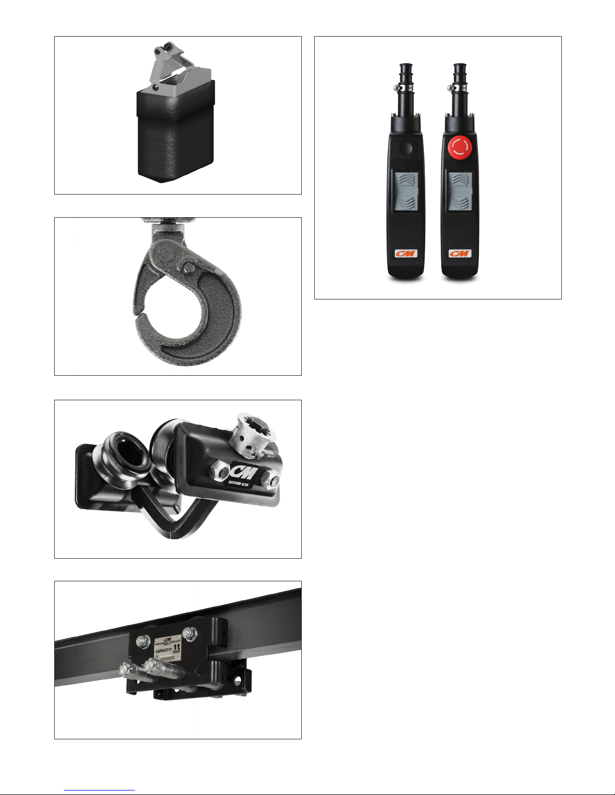
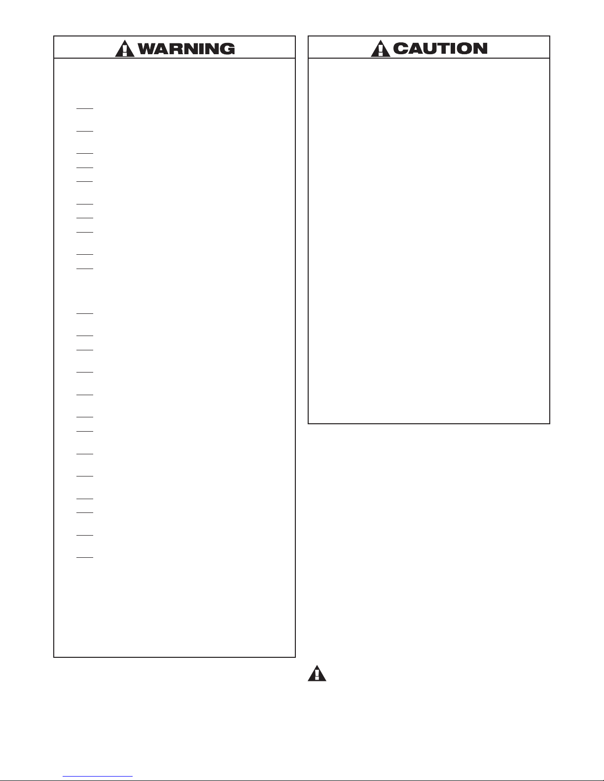
Figure 1 - Chain Container
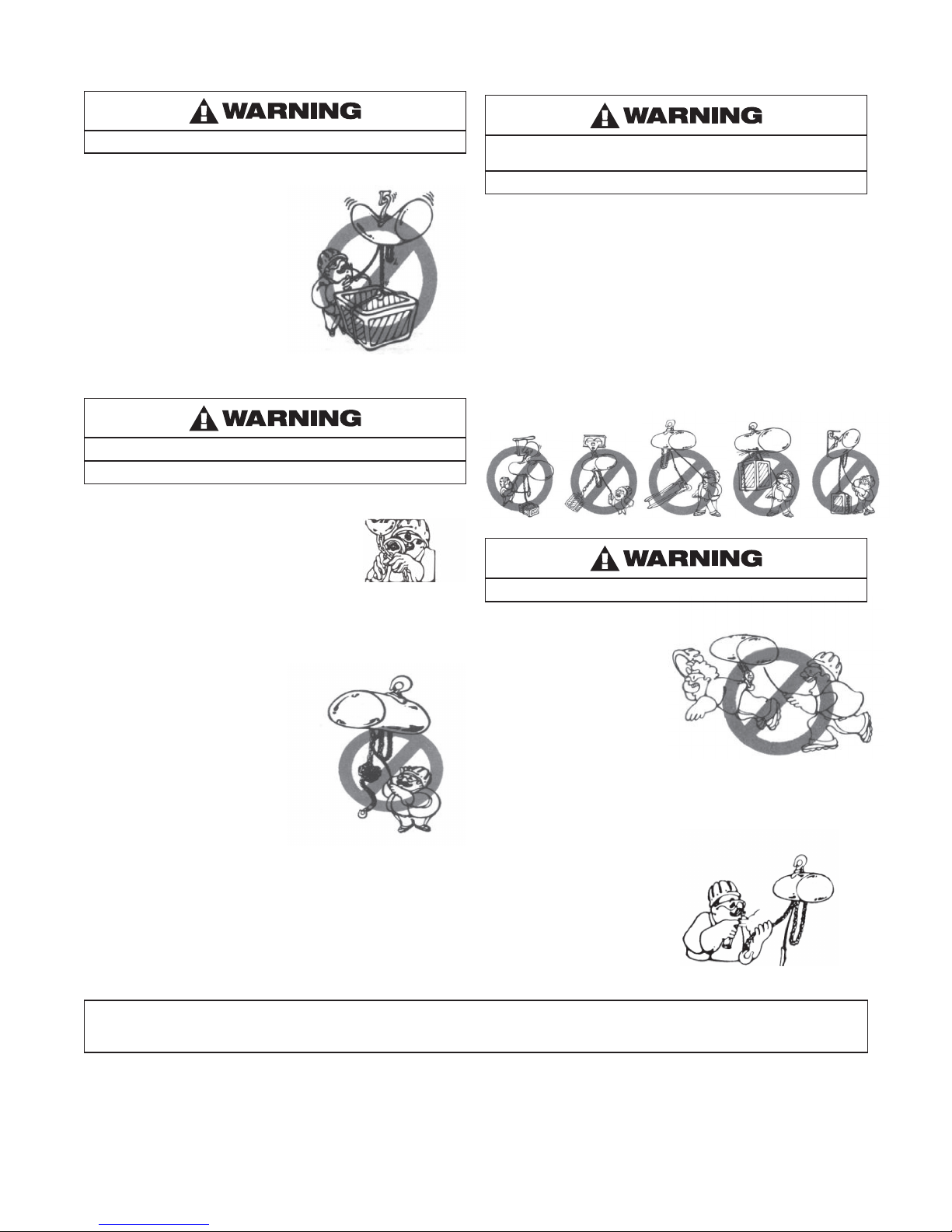
Figure 2 - Latchlok Hook
Figure 5 - CM® Rocket™ Universal Pendant Control
ACCESSORIES
HOOK SUSPENSIONS
Swivel and rigid type hook suspensions are available for all Shopstar
Electric Hoists. However, swivel type hook suspensions are normally
recommended for most applications.
CHAIN CONTAINER
This accessory item (Figure 1) is used to hold the slack chain
and it is supplied with mounting hardware and instructions.
Chain containers are recommended for those applications where
slack chain will interfere with the load or drag on the oor as may
more often be the case with the double-reeved units (500, 600,
1,000lb - 226, 272, and 453kg). Chain containers are shipped
separately and can be furnished for units already in service.
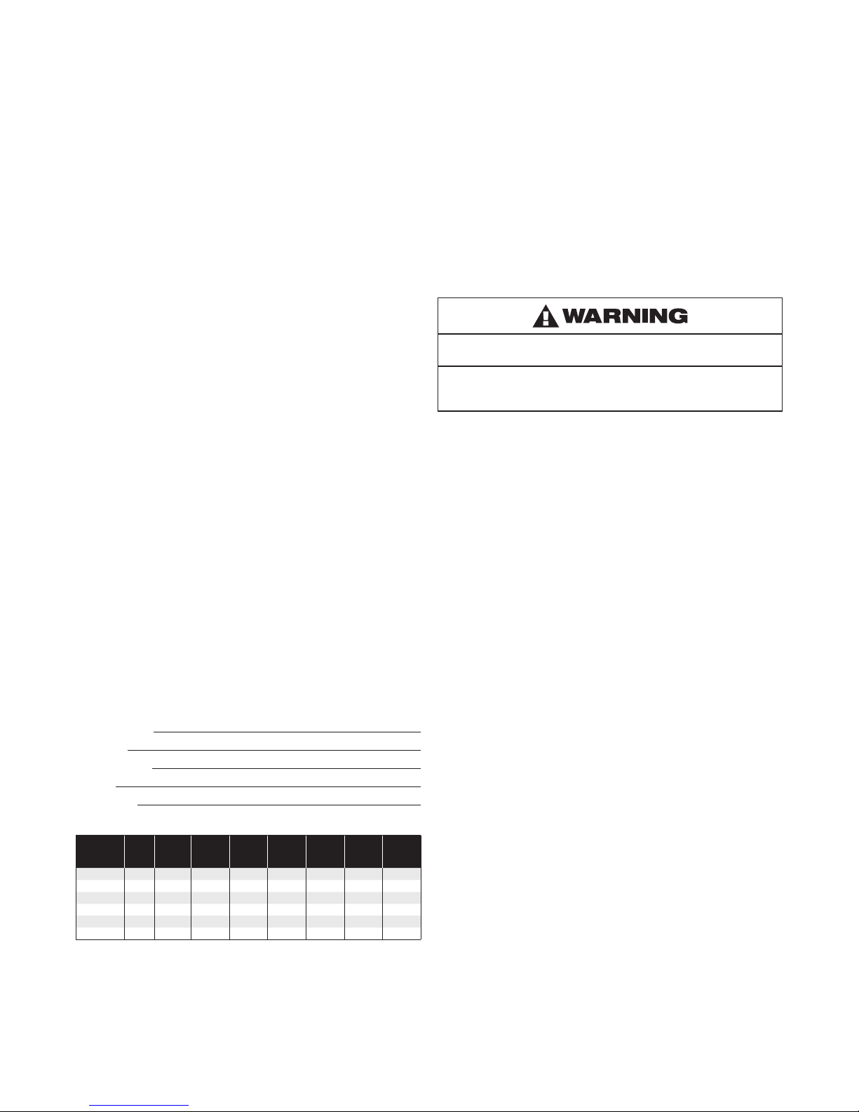
Figure 3 - 632 Trolley
Figure 4 - UT Trolley
LATCHLOK
®
HOOKS
CM’s Latchlok hooks are available (Figure 2) to replace the standard
upper and lower hooks used on the Shopstar Electric Hoists.
CM SERIES 632 TROLLEY
This lightweight, yet, rugged, manual push type trolley (Figure 3)
is designed to t a wide range of monorail beams and negotiate
tight curves. Provides mobility of your hoist.
CM UNIVERSAL (UT) TROLLEY
The CM Universal Trolley (UT) is designed to t virtually all
Columbus McKinnon powered chain hoists up to 3 ton capacities.
The rugged UT is available as a convertible plain unit, a geared unit
ideal for precise hoist positioning, and a motorized unit that’s perfect
for applications requiring high cycling and long distance hoist travel.
CM® ROCKET™ UNIVERSAL PENDANT CONTROL
The CM Rocket Pendant Control is engineered for maximum
operator comfort, while delivering the precision control your
application demands.
7
P/N 192047138 Rev AA November 2017
Page 8
INSTALLATION
UNPACKING
After opening the carton, carefully inspect the hoist frame, cords,
hooks, chain and control station for damage that may have occurred
during shipment. If there is damage, refer to the packing slip
envelope.
Make sure that the power supply to which the hoist is to be
connected is the same as that shown on the identication plate
located on bottom of hoist.
Operating a unit with obvious external damage may cause load to
drop and that may result in personal injury and/or property damage.
TO AVOID INJURY:
Carefully check unit for external damage prior to installation.
MOUNTING THE HOIST
Hang the hoist from its intended support. The structure used to
support the hoist must have sufcient strength to withstand several
times the load imposed. If in doubt consult a registered engineer
and local building codes.
Suspending the hoist from an inadequate support may allow the
hoist and load to fall and cause injury and/or property damage.
TO AVOID INJURY:
Make sure the attachment point has sufcient strength to hold
several times the hoist and its rated load. Using the upper hook,
hang the hoist from the support. Be sure hoist is solidly held
in the uppermost part of the hook arc and the latch is tightly
against the hook tip.
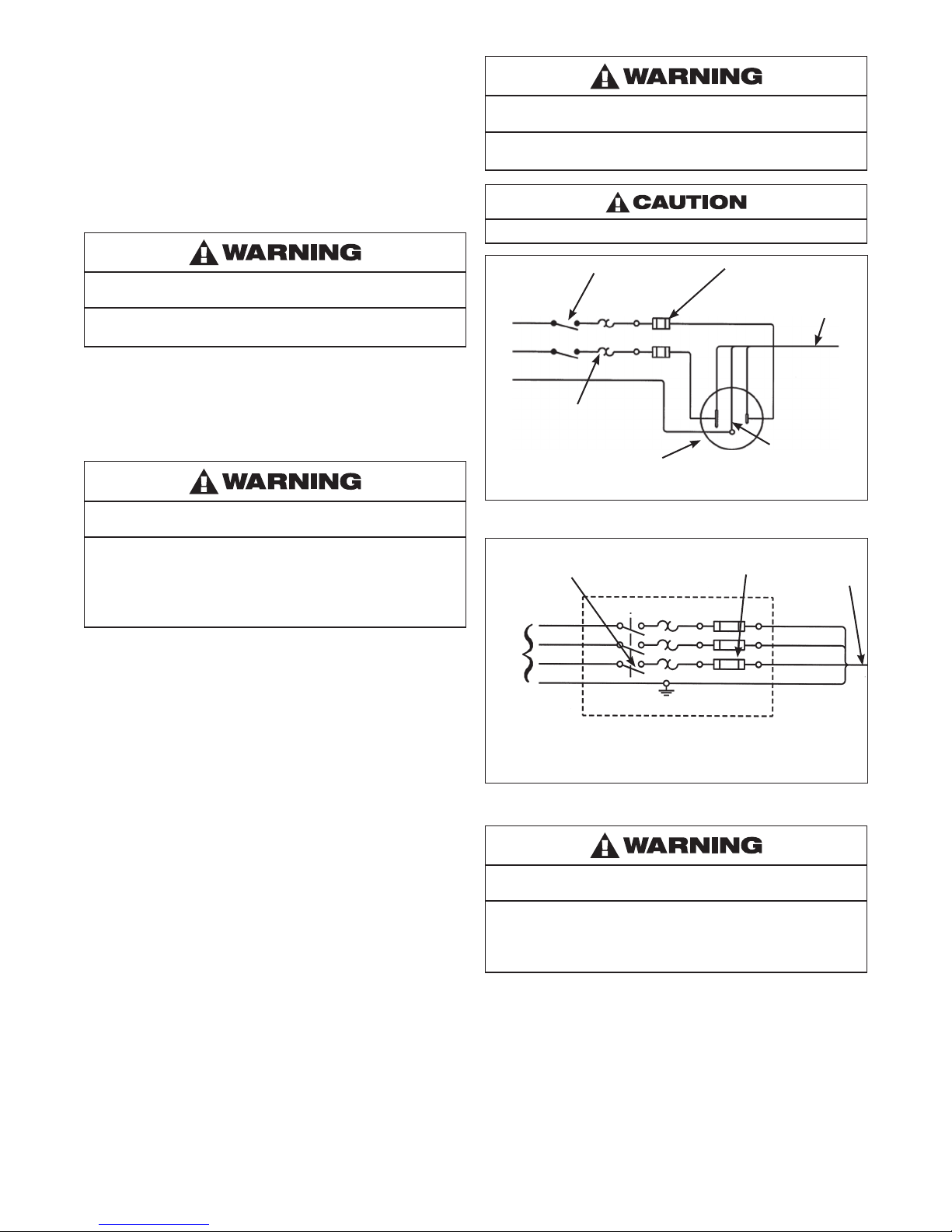
POWER SUPPLY SYSTEM
(Refer to Figure 6 or 7). To insure proper operation, to avoid damage
to hoist and electrical system and to reduce the risk of electric shock
or re, the branch circuit supplying power to the hoist must:
1. Have ample capacity to prevent excessive voltage drop during
starting and operation (refer to Figure 8). When determining
the size of branch circuit components and conductors,
special consideration should be given to the starting
current-amps (approximately three times that shown on the
hoist identication plate) and the length of the conductors.
As a minimum, the system should be rated for 15 amps and
it should have #16 AWG, or larger, wiring.
2. Be in accordance with the National Electrical Code (ANSI/
NFPA-70) and applicable National, State and Local Codes.
3. Effectively ground the hoist in accordance with National
Electrical Code and other applicable codes. Proper grounding
provides a path of least resistance for electric current to reduce
the risk of electric shock. The power cord of the hoist includes
a green-yellow wire for grounding the hoist to the external
power supply system. Be sure that the receptacle opening that
receives the longest prong is properly grounded. If grounding
is to be through the trolley trackwheels, each section of the
runway must be grounded to the building ground system
using metal to metal connections.
4. Include slow blow type fuses or inverse trip time circuit
breakers to permit the hoist to start and accelerate load.
5. Include a disconnecting means capable of being locked in the
“open” position.
Failure to properly ground the hoist presents the danger of
electric shock.
TO AVOID INJURY:
Permanently ground the hoist as instructed in this manual.
To reduce the risk of electric shock or injury, use indoors only.
Manual
Disconnect
Switch
Black
White
Ground
Thermal
Overload
Relay
Receptacle Rated for 15 amp Minimum (220-1-50 units do
not include Power Cord Plug). Wire Blue and Brown Wires to
Fuses or Circuit Breakers and Green-Yellow Wire to Ground.
Slow Blow Fuses or
Inverse Time Circuit
Breakers
Blue
Hoist Power
Cord
Brown
Green-Yellow
Figure 6 - Single Phase Systems
Manual
Disconnect
Switch
L1
L2
L3
Ground
Incoming Power
Must be per National Electrical Code and These Devices are
to be Supplied by the User.
Slow Blow Fuses or
Inverse Time Circuit
Breakers
Hoist Power
Cord
Black
Grey
Brown
Green-Yellow
Figure 7 - Three Phase Systems
Failure to provide a proper power supply system for the hoist may
cause hoist damage and offers the potential for a re.
TO AVOID INJURY:
Provide the hoist with a 15 amp, minimum, overcurrent protected
power supply per the National Electrical Code (ANSI/NFPA 70) and
applicable local codes as instructed in this manual.
8
P/N 192047138 Rev AA November 2017
Page 9
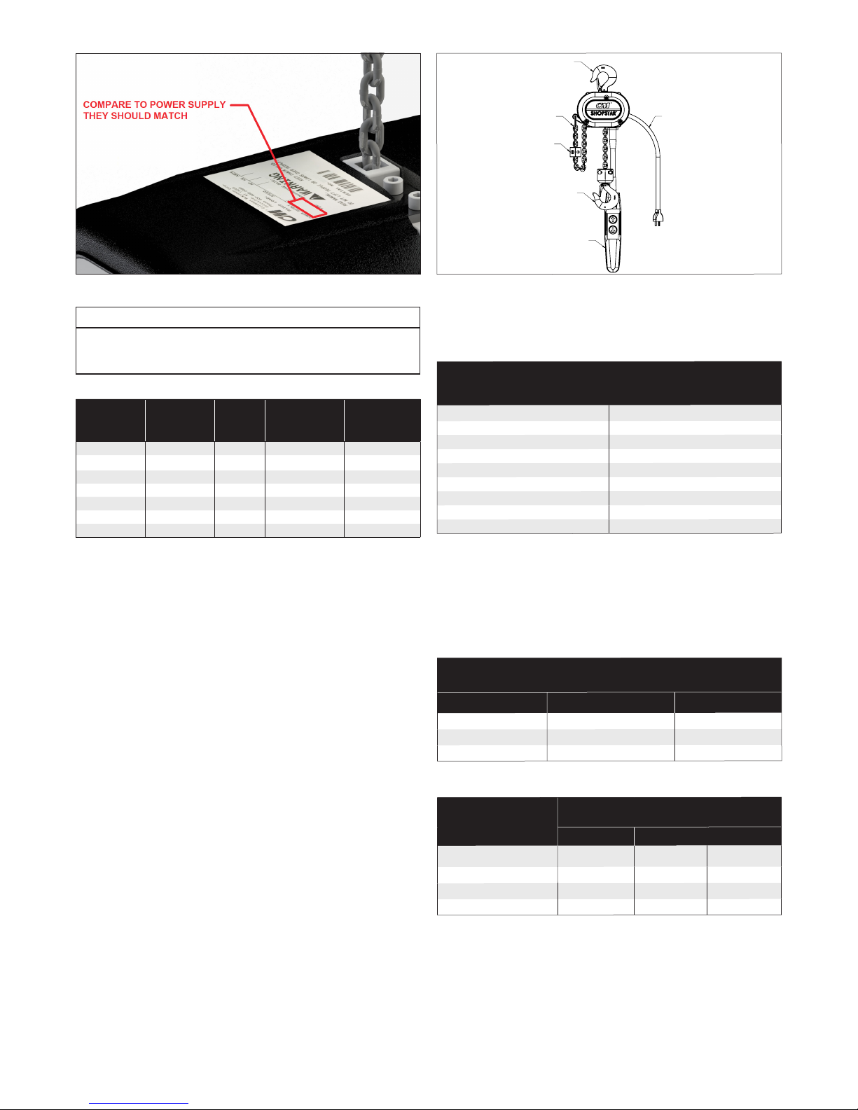
Figure 8 - Nameplate
UPPER HOOK
LOOSE END OF CHAIN
CHAIN STOP
LOWER HOOK
POWER
CORD
CONTROL STATION
Note
In this manual, nominal voltages are used when referring to power
supply systems. However, with no modication, the Shopstar
Hoist will operate on a range of voltages as indicated below:
Table 2 - Nominal Voltage
NOMINAL
VOLTAGE
VOLTAGE
RANGE
HERTZ
TRADITIONAL
CONTACTOR
230 208-240 60 AVAILABLE AVAILABLE
460 440-480 60 AVAILABLE NOT AVAILABLE
220 200-240 50 AVAILABLE AVAILABLE
380 365-395 50 AVAILABLE AVAILABLE
415 400-415 50 AVAILABLE AVAILABLE
430 415-430 50 AVAILABLE NOT AVAILABLE
575 550-600 60 AVAILABLE NOT AVAILABLE
THREE PHASE HOISTS
Since the motor in a three phase hoist can rotate in either direction,
depending on the manner in which it is connected to the power
supply, the direction of hook movement must be checked during
the original installation and each time hoist is moved to a new
location as follows:
1. Move the manual disconnect switch handle to the
“OFF” position.
2. Connect the BROWN, GREY AND BLACK wires of hoist
power cord to load side of disconnect switch. Connect
the GREEN-YELLOW wire of hoist power cord to power
supply ground.
3. Move the manual disconnect switch handle to the
“ON” position.
4. Depress the (up) control. If the hook moves in the up direction,
the hoist is ready for operation. If the hook lowers, move
the disconnect switch handle to the “OFF” position and
interchange the BLACK and BROWN leads at the disconnect
switch. Move the disconnect switch handle to the “ON”
position and the hoist is now ready for operation.
CHECKING FOR ADEQUATE VOLTAGE AT HOIST
The hoist must be supplied with adequate electrical power for proper
operation and to reduce problems that may result from insufcient
power (low voltage). These include:
• Noisy hoist operation due to brake and/or contactor chatter.
• Heating of the hoist motor and other internal components as well
as heating of wires and connectors in the circuit feeding the hoist.
• Failure of the hoist to lift the load due to motor stalling.
• Blowing fuses or tripping circuit breakers.
• Dimming of lights or slowing of motors connected to the
same circuit.
PRINTED
CIRCUIT BOARD
Figure 9 - Hoist Components
For proper operation and to avoid these low voltage problems,
voltage (measured at end of the power cord while lifting rated load)
should be as the following chart indicates.
Table 3 - Start-up Voltage
NOMINAL MINIMUM * MIN. VOLTAGE
POWER OPERATING AT INSTANT
SUPPLY VOLTAGE OF START
115-1-50/60 108
220-1-50 198
208-3-60 187
220-3-50 198
230-3-60 207
380-3-50 365
415-3-50 399
460-3-60 414
575-3-60 518
*The drop in voltage upon energizing the hoist should not be below the value listed.
Low voltage can also be caused by using an undersize extension
cord to supply power to the hoist. The following charts should be
used to determine the size wires in the extension cord in order to
minimize the voltage drop between the power source and the hoist.
115-1-50/60 units with contactor, 220-1-50 units and three phase
units (hoists with black control station)
Table 4a - Adequate Power Supply
MAXIMUM LENGTH OF EXTENSION CORD
Wire Size Single Phase Hoist Three Phase Hoist
#16 A.W.G. 135 ft (40m) 245 ft (73m)
#14 A.W.G. 220 ft (66m) 395 ft (120m)
#12 A.W.G. 354 ft (107m) 630 ft (192m)
115-1-50/60 units without contactor (hoists with orange control station)
Table 4b - Adequate Power Supply
LENGTH OF CONTROL
CORD ft(m)
MAXIMUM LENGTH OF EXTENSION CORD
BASED ON SIZE OF WIRE
#16 AWG #14 AWG #12 AWG
1.0 to 10.0 (0.3 to 3.0) 105ft (32m) 170ft (51m) 270ft (82m)
11.1 to 20.0 (3.1 to 6.0) 75ft (22m) 120ft (36m) 190ft (58m)
21.1 to 30.0 (6.1 to 9.0) 45ft (14m) 70ft (21m) 110ft (33m)
31.1 to 40.0 (9.1 to 12.0) 15ft (4.5m) 20ft (6m) 35ft (11m)
After the hoist is suspended from its support and you have made
sure the power supply complies with the above, the hoist is ready
for operation.
On the Double units, cut and discard the ties used to hold the two
strands of chain together. With no load on the lower hook, depress
the UP button in the control station and raise the lower hook
until it is about 2 feet below the bottom of the hoist. Check both
strands of chains for twists. Twists occur if the lower hook block
has been capsized between the strands of chain during packing,
shipment and/or handling. Reverse the capsize to remove twists.
9
P/N 192047138 Rev AA November 2017
Page 10
OPERATING INSTRUCTIONS
The hoist is equipped with a Protector™ that is designed to
allow the rst gear to slip on an excessive overload. An overload
is indicated when the hoist speed slows down, it raises the load in
a jerky manner or it will not lift the load at all. Also, some clutching
noise may be heard if the hoist is loaded beyond rated capacity.
Should this occur, immediately release the UP button to stop the
operation of the hoist. At this point, the load should be reduced to
the rated capacity or the hoist should be replaced with one of the
proper capacity. When the excessive load is removed, normal hoist
operation is automatically restored.
The Protector™ is susceptible to overheating and wear when slipped
for extended periods. Under no circumstance should the Protector
be allowed to slip for more than a few seconds.
Due to the above, the hoist is not recommended for use in any
application where there is a possibility of adding to an already
suspended load to the point of overload. This includes dumbwaiter
installations, containers that are loaded in mid-air, etc. Also, if the
hoist is used at unusual extremes of ambient temperatures, above
150º F (65ºC). or below 15ºF (-9ºC)., changes in lubricant properties
may permit the hoist to raise larger loads than under normal
operating conditions and present possibility of damage or injury.
On units without contactor (hoists with orange control station)
it is necessary to stop the hoist before changing direction.
Therefore, when lowering a load, the push button in the control
station must be released momentarily before the UP button is
depressed to raise the load. If this is not done, the hoist will
continue to operate in the down direction while the UP push
button is depressed, and it will continue to lower the load until
the control push button is released. As a result, the direction
must not be reversed quickly (plug reversed).
There are no electrical switches to stop the operation of the hoist
at the upper and lower limits of lift. As a result, it is necessary to
release the push button in the control station to stop the hoist
components from damage. However, continued, prolonged or
repeated slipping of the Protector will damage the Protector and
cause overheating of the internal hoist components.
Allowing the hook block to run into the hoist when raising a load or
allowing the chain stop to run into the hoist when lowering a load
may break the chain and allow the load to drop.
TO AVOID INJURY:
Do not allow the hook block or the chain stop to contact the hoist frame.
Hoist operation is controlled by depressing the control station push
buttons. Depressing the UP push button will move the load hook
toward the hoist head; depressing the DOWN push button will move
the load hook away from the hoist head.
The UP and DOWN buttons are momentary type and the hoist will
operate in the selected direction as long as the button is held in the
depressed position. Release the push button and the hoist will stop.
It is preferred that the load always be tied off with auxiliary chains or
cables before access to the area beneath the load is permitted. As
an alternative, the system may be designed such that malfunction or
failure of one hoist’s load bearing components does not cause load
loss and/or overloading of any other hoists in the system. Note that
in such a system, hoist performance and function must be monitored
visually or with the use of load cells. Check the supporting structure
to which the load hook is to be attached. Make sure the attachment
point as well as the structure have sufcient strength to withstand
several times the load imposed. If in doubt, consult a registered
engineer and local building codes.
10
P/N 192047138 Rev AA November 2017
Page 11
Attaching the load hook to an inadequate support may allow the
hoist and load to fall and cause injury and/or property damage.
TO AVOID INJURY:
Make sure the structure and the load hook attachment point have
sufcient strength to hold several times the hoist and rated load.
1. When preparing to lift a load, be sure that the attachments to
the load hook are rmly seated in hook saddle. Avoid off center
loading of any kind, especially loading on the point of the hook.
2. When lifting, raise the load only enough to clear the oor or
support and check to be sure that the attachments to the
hook and load are rmly seated. Continue lift only after you are
assured the load is free of all obstructions.
3. Do not load the hoist beyond the rated capacity shown on the
brake end cover. Overloading can cause immediate failure of
some load-carrying part or create a defect causing subsequent
failure at less than rated capacity. When in doubt, use the next
larger capacity of hoist.
4. Do not use this or any other overhead materials
handling equipment for lifting persons or allow people
on unsecured load.
5. Stand clear of all loads and avoid moving a load over heads
of other personnel. Warn personnel of your intention to move
a load in their area. Do not leave unsecured load over people.
6. Do not leave the load suspended in the air unattended.
7. Permit only qualied personnel to operate unit.
8. Do not wrap the load chain around the supporting structure and
hook onto itself as a choker chain. Doing this will result in:
1. The loss of the swivel effect of the load hook which could
mean twisted chain and a jammed liftwheel.
2. The chain could be damaged at the load hook.
9. On the Double-reeved hoists, check for twists in the load chain.
A twist can occur if the lower block has been capsized between
the strands of chain. Reverse the capsize to remove twist.
10. Do not allow a load to bear against the hook latch. The latch
is to help maintain the hook in position while the chain is slack
before taking up the slack chain.
11. Take up a slack load chain carefully and start load easily to
avoid shock and jerking of hoist chain. If there is any evidence
of overloading, immediately lower the load and remove the
excess load.
12. Do not allow the load to swing or twist while hoisting.
13. Never operate the hoist when ammable materials or vapors
are present. Electrical devices produce arcs or sparks that can
cause a re or explosion.
14. STAY ALERT! Watch what you are doing and use common
sense. Do not use the hoist when you are tired, distracted or
under the inuence of drugs, alcohol or medication causing
diminished control.
TO AVOID INJURY:
DO NOT Lift more than rated load.
DO NOT Operate with twisted, kinked or damaged chain.
DO NOT Operate damaged or malfunctioning hoist
DO NOT Lift people, loads over people, allow people on
unsecured load or leave unsecured load over people.
DO NOT Operate hoist when load hook is not centered overhoist.
DO NOT Permit load hook block to contact hoist frame or
chain container.
DO Replace damaged or malfunctioning hook latch.
DO Keep load chain well oiled.
DO Read ASME B30.16 Safety Code for Hoist and appropriate
operating instructions.
MAINTENANCE
INSPECTION
To maintain continuous and satisfactory operation, a regular
inspection procedure must be initiated to replace worn or damaged
parts before they become unsafe. Inspection intervals must be
determined by the individual application and are based on the type
of service to which the hoist will be subjected. The type of service to
which the hoist is subjected can be classied as “Severe”, “Normal”,
or “Stand by Service” per ANSI E1.6-2.
Severe Service: Hoist operates in excess of 200 days a year.
Normal Service: Hoist operates 200 or fewer days a year but
more than 25.
Stand by Service: Hoist operates 25 or fewer days per year
but at least once per year.
Two classes of inspection - frequent and periodic – must
be performed.
Frequent Inspections: Visual examination shall be performed by
a competent person following the items listed in the inspection table
Records of such inspections are recommended.
Periodic Inspections: Inspection shall be performed by a qualied
person following the items listed in inspection table. Records of
this inspection shall be recorded and retained for a minimum of 36
months after the hoist is taken out of service.
Lifting and lowering functions shall be tested under no-load
conditions. (Testing through complete rated lift length is
not required). Brake(s) operation shall be tested under
no-load conditions.
Any deciencies found during inspections are to be corrected
before the hoist is returned to service. Also, the external
conditions may show the need for disassembly to permit a
more detailed inspection, which, in turn, may require the use of
nondestructive type testing.
PREVENTIVE MAINTENANCE
In addition to the above inspection procedure, a preventive
maintenance program should be established to prolong the useful
life of the hoist and maintain its reliability and continued safe use.
The program should include the periodic and frequent inspections
with particular attention being paid to the lubrication of the various
components using the recommended lubricants (see page 15).
Note
To perform some of the periodic inspections, it is necessary to
partially disassemble the hoist. Refer to Disassembly - Assembly
starting on page 23.
Any deciencies noted must be corrected before the hoist is
returned to service. Also, the external conditions may show the
need for more detailed inspection which, in turn, may require the
use of nondestructive-type testing.
Any parts that are deemed unserviceable are to be replaced with
new parts before the unit is returned to service. It is very important
that the unserviceable parts be destroyed to prevent possible future
use as a repair item and properly disposed of.
Allowing a load to bear against the hook latch and/or hook tip can
result in loss of load.
TO AVOID INJURY:
Do not allow a load to bear against the hook latch and/or hook tip.
Apply load to hook bowl or saddle only
11
P/N 192047138 Rev AA November 2017
Page 12

Service Classifications
Severe Normal Stand By Rental
Frequent Inspections
Inspection Table
ITEM
Out of
Service
Hoist braking system for proper operation.
Hooks and attachment hardware for correct assembly,
damage, cracks, twists, excessive throat openings, latch
engagement, and latch operation.
Weekly to Monthly
Every 3 Months
Periodic Inspections
Monthly
Yearly
or Rental
Every 3 Months
Yearly
Prior to Next Use
Yearly
Load chain for adequate lubrication, signs of wear, damaged
links, corrosion, or foreign matter.
Load chain for proper reeving and twists.
Limit switches for function, if equipped
All items listed in Inspection Table for frequent inspections.
Evidence of loose screws, bolts or nuts.
Evidence of worn, corroded, cracked or distorted hook block
body, suspension screws, gears, bearings, chain dead end
and chain pin.
Evidence of damage or excessive wear of the lift wheel and
hook block sheave chain pockets.
Link by link inspection of the chain for evidence of excessive
interlink wear and damage.
Prior to Reintroduction into Service
Evidence of chain guide wear or damage where the chain
enters the hoist.
Evidence of excessive wear and/or damage of brake parts.
Proper brake adjustment.
If the hoist is equipped with a reversing contactor, inspect
contactors for functionality and free operation of the interlock.
Electrical cords, grommets, connectors, cables, and control
station enclosure (if applicable) for damage or wear.
Check bearings for excessive wear or damage.
Suspension components for damage, cracks, wear and
correct operation.
Evidence of lubricant leakage.
12
P/N 192047138 Rev AA November 2017
Page 13

HOOK INSPECTION
Hooks damaged from chemicals, deformations or cracks, or any
visibly apparent bend or twist from the plane of the unbent hook,
excessive opening or seat wear must be replaced. Also, hooks
that are opened and allow the latch to not engage the tip must be
replaced. Any hook that is twisted or has excessive throat opening
indicates abuse or overloading of the unit. Inspect other load
sustaining parts, hook block screws, load pins and hook block
bodies for damage.
On latch type hooks, check to make sure that the latch is not
damaged or bent and that it operates properly with sufcient spring
pressure to keep the latch tightly against the tip of the hook and
allow the latch to spring back to the tip when released. If the latch
does not operate properly, it should be replaced. See Figure 8 to
determine when the hook must be replaced.
Suspension bolts should be replaced any time the suspension
is removed from the hoist.
HOOK REPLACEMENT CRITERIA
Based on ASME B30.10, hooks shall be removed from service if
damage such as the following is visible and shall only be returned
to service when approved by a qualied person:
1. Missing or illegible rated load identication or illegible
hook manufacturers’ identication or secondary
manufacturer’s identication.
2. Excessive pitting or corrosion. Cracks, nicks, or gouges.
3. Wear--any wear exceeding 10% of the original section
dimension of the hook or its load pin.
4. Deformation--any visibly apparent bend or twist from the
plane of the unbent hook.
5. Throat opening-any distortion causing an increase in the
throat opening of 5% not to exceed 1/4” (6mm).
6. Inability to lock- any self-locking hook that does no lock.
7. Inoperative latch, any damaged latch or malfunctioning
latch that does not close the hook’s throat.
8. Thread wear, damage, or corrosion.
9. Evidence of excessive heat exposure or unauthorized welding.
10. Evidence of unauthorized alterations such as drilling,
machining, grinding, or other modications.
INSPECTING THE LOAD CHAIN
The chain must be inspected at regular intervals, with a minimum
of once annually. As the frequency of use increases, the time
Intervals between inspections must be reduced. During inspection,
the chain link must be examined along their entire length, including
the hidden parts. If the lifting equipment is frequently used with a
constant lifting distance or in other words the switch from upward to
downward often takes place in the same area, a particularly thorough
inspection and lubrication is required in that area. Worn chain can
also be an indication of worn hoist components. For this reason, the
hoist’s chain guides, hook blocks and liftwheel (sprocket) should be
examined for wear and replaced as necessary when replacing chain.
1. Check to see if chain is dirty or poorly lubricated.
2. Clean the chain with a non-caustic/non-acid type solvent
and make a link by link inspection for wear or cracks in the
links, twisted or deformed links. Chain with any one of these
defects must be replaced.
3. Slack the portion of the chain that normally passes over
the lift-wheel (sprocket) or idler sprocket on multi-reeved
hoist. Examine the chain links for wear. If the wire diameter
anywhere on the link measures less than 90% of the nominal
wire diameter, the chain must be replaced.
4. Based upon ASME B30.16, should also be checked for
elongation. Select an unworn, un-stretched length of the
chain (at the slack end for example). Suspend the chain
vertically under tension and using a knife blade caliper
type gauge, measure the outside length of any convenient
number of links, 11 is recommended. Measure the same
number of links in the used sections and calculate the
percentage in increased length. The chain should be
replaced if the length of the used portion is more than
1.5% longer than the unused portion of the chain. Also,
if the pitch of any individual link has elongated by more
than 5%, the chain should be replaced.
Figure 10 - Hook Inspection
Latch Type Hook Latchlok® Hook
“A” Max “B” Min “A” Max “B” Min
1.12” (28.5mm) .71” (18.0mm) 1.48” (37.7mm) .75” (18.8mm)
13
P/N 192047138 Rev AA November 2017
Page 14

Figure 11: Chain Inspection
Use only a “Knife-edge” caliper to eliminate possibility of false
reading by not measuring full pitch length.
Note that worn chain can be an indication of worn hoist
components. For this reason, the hoist’s chain guide, hook
block and liftwheel should be examined for wear and replaced
as necessary when replacing worn chain.
Also, these chains are specially heat treated and hardened and
should never be repaired.
IMPORTANT: Do not use replaced chain for other purposes such
as lifting or pulling. Load chain may break suddenly without visual
deformation. For this reason, cut replaced chain into short lengths
to prevent use after disposal.
CHAIN LUBRICATION
A small amount of lubricant will greatly increase the life of load
chain. Do not allow the chain to run dry.
Keep it clean and lubricate at regular intervals with Lubriplate®
Bar and Chain Oil 10-R (Fiske Bros. Rening Co.) or equal lubricant.
Normally, weekly lubrication and cleaning is satisfactory, but under
hot and dirty conditions, it may be necessary to clean the chain at
least once a day and lubricate it several times between cleaning.
When lubricating the chain, apply sufcient lubricant to obtain
natural run-off and full coverage, especially in the interlink area.
Used motor oils contain known carcinogenic materials.
Figure 12: Chain Wear Areas
Use only Star (H) grade load chain and factory replacement
parts. Use of other chain and parts may be dangerous and
voids factory warranty.
Figure 13: Chain Identification
Use only Star (*) grade load chain and original replacement
parts. Use of other chain and parts may be dangerous and
voids factory warranty.
IMPORTANT: Do not use replaced chain for other purposes such
as lifting or pulling. Load chain may break suddenly without visual
deformation. For this reason, cut replaced chain into short lengths
to prevent use after disposal.
Use of commercial or other manufactures’ chain and parts to repair
hoists may cause load loss.
TO AVOID INJURY:
Use only factory supplied replacement load chain and parts.
Chain and parts may look alike, but our chain and parts are made
of specic materials or processed to achieve specic properties.
TO AVOID HEALTH INJURIES
Never use used motor oils as a chain lubricant. Only use
Lubriplate® Bar and Chain Oil 10-R as a lubricant for the load
chain.
LUBRICATION
To assure extra long life and top performance, be sure to lubricate
the various parts of the Shopstar Hoist using the lubricants specied
below. If desired, these lubricants may be purchased from the
factory. Contact customer service for more information.
The lubricants used in and recommended for the Shopstar Hoist
may contain hazardous materials that mandate specic handling
and disposal procedures.
TO AVOID CONTACT AND CONTAMINATION:
Handle and dispose of lubricants only as directed in applicable
material safety data sheets and in accordance with applicable
local, state and federal regulations.
Part Number for Packaged Lubricants used
on the Shopstar Electric Chain Hoists
Lubricant Usage Type of Lubricant
Hoist Gears Grease (Special) 28605
Lower Hook Thrust
Bearing
*These oils are not furnished by CM in Packaged Quantities. When ordering lubricants, specify
the type of lubricant, part number and packages quantity required.
*Oil
GEARS
The Protector (620-111) should operate for the normal life of the
hoist without service. The device has been lubricated and calibrated
by the factory and should not be adjusted.
Part Numbers and Packaged
Quantity of Lubricants
Heavy Machine Oil obtain
locally
14
P/N 192047138 Rev AA November 2017
Page 15

The Protector™ is to be used with “Century Lubricants HB-11,
#3” grease. Do not use any other grease or the Protector will not
operate properly and parts could be damaged.
The gears and Protector are packed at assembly with grease and
should not need to be renewed unless the gears have been removed
from the housing and degreased.
Never degrease the Protector™ or attempt to disassemble this
device. Degreasing the Protector may damage parts and using a
device that has been degreased may cause erratic, inconsistent
operation. If the Protector has been degreased, it must be
replaced by a factory calibrated device.
Bra ke Asse mb ly
Brake Base Plate
First Pinio n
Sh a f t
Gap
Brake Field
A ssem b ly Inc lud es Co il
Brak e A rma tu re
Brak e Sp ring
CHAIN GUIDE, LIFTWHEEL AND SHEAVE WHEEL
When the hoist is disassembled for inspection and/or repair, the
chain guide, stripper, sheave wheel (on double chain unit) and
liftwheel must be lubricated with Lubriplate® Bar and Chain Oil
10-R (Fiske Bros. Rening Co.) prior to reassembly. The lubricant
must be applied in sufcient quantity to obtain natural runoff and full
coverage of these parts.
LOAD CHAIN
Refer to page 13 for lubrication of the load chain.
EXTERIOR FINISH
The exterior surface of the hoist has a durable, scratch resistant
baked powder coating. Normally, the exterior surfaces can be
cleaned by wiping with a cloth. However, if the nish is damaged,
compatible touch-up paint can be purchased from the factory. Refer
to page 19 for information on ordering the paint.
ELECTRIC BRAKE
The brake is non-adjustable with a nominal .004 inch (0.102 mm) air
gap and the brake disc must be replaced when the air gap reaches
.012 inch (0.305 mm). The brake spacer should be no more than
.012 inch (0.305 mm) thicker than the combined thickness of the
brake disc and armature plate. Refer to Figure 16.
Brak e D river
Bra k e D isc
Figure 14: Brake Field Assembly
Figure 15: Drive Shaft Assembly
If the gears are removed from the housing, wipe the excess grease
off the outside surfaces of the Protector with a soft cloth and
degrease the remaining gears and housings. Upon reassembly,
add 2 oz. of the above grease to gears and housing. Also, coat the
spline on the end of the rst pinion and shaft with a Molydisulphide
lubricant such as Moly-Duolube 67 (Hercules Packing Co.)
BEARINGS
Rotor bearings are pre-lubricated and require no lubrication. Needle
bearings) are packed at assembly with grease and should not need
to be relubricated. However, if the housings, liftwheel or sheave
wheel have been degreased, these bearings should be greased
using “Century Lubricants HB-11, #3” grease.
SEALS
When reassembling the unit, wipe the inside surface of the seals
with “Century Lubricants HB-11, #3” grease.
HOOK BLOCK
If the hook blocks are disassembled for inspection purposes, wipe
the grease from the hook knob and the hook knob cavities in the
hook blocks. At reassembly, coat the underside of the hook knob
and the knob bearing surfaces of cavities in the hook blocks with
Molykote BR-2-S (Dow Corning Corp.) grease or equivalent.
Figure 16: Brake Assembly
Failure to follow proper lockout/tagout procedures may present the
danger of electrical shock.
TO AVOID INJURY:
Disconnect power and lockout/tagout disconnecting means before
removing cover or servicing this equipment.
To inspect the brake gap, disconnect the hoist from power and
remove brake end cover.
1. Refer to Figure 16 and disassemble the brake. Depress and
hold the eld assembly while removing the four brake screws.
The eld assembly is under spring pressure and will spring-out
if not held. Examine the base plate, brake disc) and armature
for excessive wear, scoring or warpage. Make sure the brake
disc is not glazed, the coil rmly xed in the eld) and the
brake spring is not damaged. Worn, scored, warped, glazed or
damaged parts should be replaced before preceding.
2. Refer to Figure 16 and assemble the brake. Depress and hold
the eld assembly while installing the four brake screws through
the brake parts and mount the brake on the gear housing.
Tighten the four brake screws to 25 in.lb.
PROTECTOR™
The Protector should operate for the normal life of the hoist without
service. The device has been lubricated and calibrated and it should
not be adjusted. If the Protector is not operating properly (see
testing on page 13), it must be replaced with a properly calibrated
unit from the factory.
PREVENTATIVE MAINTENANCE
A preventative maintenance program should be established to
prolong the useful life of the hoist and maintain its reliability and
continued safe use. The program should include the periodic and
frequent inspections with particular attention being paid to the
lubrication schedule on page 12.
15
P/N 192047138 Rev AA November 2017
Page 16

TROUBLESHOOTING CHART
Always disconnect unit from the power supply system before removing hoist covers or the back cover of control station.
Symptom Possible Cause(s) Corrective Action
1. Hook does not respond to the control
station
A.) No voltage at hoist-main line or branch circuit switch open;
branch line fuse blown or circuit breaker tripped.
A.) Check for blown fuse or tripped circuit breaker
or open disconnect switch in main line or branch
circuit. Replace fuse, reset circuit breaker or
close switch.
B.) Open control circuit due to loose connections or broken wires in
circuit; motor thermal protector open; control station contacts
not closing; open or Shorted winding in transformer; transformer
thermal cut-out open; mechanical binding in contactor; open
or shorted winding in contactor coil or blown Printed Circuit
Board fuse.
C.) Wrong voltage or frequency. C.) Make sure that the power supply to hoist is the
D.) Low Voltage. D.) Check power supply system to make sure it
E.) Brake not releasing due to open or shorted coil, defective diodes
or brake disc binding.
F.) Excessive load. F.) Reduce load to capacity limit as indicated on
G.) Phase failure (single phasing-three phase units only) - open circuit,
grounded or faulty connection in one line of power supply system,
hoist wiring, contactor, motor leads or windings.
2.) Hook moves in the wrong direction. A.) Wiring connections reversed in control station or hoist. A.)Use wiring diagram and check wiring connections.
B.) Failure of cut-out device (single phase units only) to effect
dynamic braking at time of reversal.
C.) Phase reversal (three phase unit only). C.) See “Three Phase Hoists.”
3.) Hook lowers but will not raise. A.) Excessive load. A.) See item 1F.
B.) Hoisting circuit is OPEN due to loose connections or broken
wire in circuit; control station contacts are not making; open or
shorted winding in contactor coil.
C.) Motor cut-out device not operating. (single phase units only). C.) Check cut-out device and connections to same.
D.) Phase failure (three phase units only). D.) See item 1G.
4.) Hook raises but will not lower. A.) Lowering circuit is OPEN due to loose connections or broken
wire; control station contacts not closing; open or shorted
winding in contactor coil.
B.) Motor reversing switch not operating (single phase unit only). B.) See item 3C
C.) Phase reversal (three phase units only). C.) See item 2C
D.) Phase failure (three phase units only). D.) See item 1G.
5.) Hook does not stop promptly. A.) Brake slipping. A.) Check electric brake, especially the brake disc for
B.) Excessive load. B.) See item 1F.
B.) Check electrical continuity thru motor thermal
protector. If it is open, allow motor to cool. If this
does not correct the trouble, use wiring diagram to
check electrical continuity of wiring, transformer,
contactor and control station contacts. Repair
wiring or replace defective part. Check Printed
Circuit Board fuse & replace if needed.
same as that shown on identification plate on
button of hoist.
complies with the requirements listed under
“power supply system” starting on page 3.
E.) Check coil continuity, diodes and connections.
Make sure brake disc slides freely on brake driver
and brake spring is not broken. Replace coil (brake
field), repair connections, remove burrs from
brake driver so that brake disc slides freely and/or
replace brake spring.
identification and capacity labels on hoist.
G.) Check for electrical continuity and repair or
replace defective part.
B.) Check connections to cut-out device. Replace
damaged device or faulty capacitor
B.) Use wiring diagram to check electrical continuity
of wiring and control station contacts. Repair wiring
or replace defective part.
Repair connections and/or replace cut-out device.
A.) See item 1B.
wear or glazing and make sure brake spring is not
broken. Replace worn or glazed brake disc or replace
brake spring.
16
P/N 192047138 Rev AA November 2017
Page 17

Symptom Possible Cause(s) Corrective Action
6.) Hoist operates sluggishly. A.) Excessive load. A.) See item 1F.
B.) Low voltage. B.) See item 1D.
C.) Phase failure or unbalanced current in the phases
(three phase unit only).
D.) Brake dragging. D.) Check electric brake. Check to make sure brake
7.) Hoist operates sluggishly. A.Excessive load. A.) See item 1F.
B.) Low voltage. B.) See item 1D.
C.) Extreme external heat. C.) Above an ambient temperature of 104°F (40°C),
D.) Frequent starting or reversing. D.) Avoid excessive inching, jogging and reversing.
E.) Brake dragging. E.) See item 6C.
F.) Motor cut-out device not opening start winding circuit (single
phase units only).
G.) Phase failure or unbalanced current in phases (three phase units
only).
8. Hook fails to stop in either direction. A.) Brake not closing or ineffective. A.) Check electric brake, and armature for binding,
9. Hook lowers when up button is
depressed.
A.) Phase reversal (three phase units only). A.) See Item 2C.
C.) See item 1G.
disc is free to move on brake driver. Check for
warped or bent brake disc and base plate. Free-up
brake disc by removing burrs on driver. Replace
warped armature base plate or brake disc.
the frequency of hoist operation must be limited
to avoid overheating the motor. Special provisions
should be made to ventilate the space around the
hoist and shield it from radiant heat.
This type of operation drastically shortens motor
cut-out device, capacitor, control station and
contactor contact life and causes excessive
brake wear.
F.) See item 3C.
G.) See Item 1G.
broken brake spring, first pinion shaft broke, brake
driver worn, brake disc worn. Correct binding of
armature; replace broken or worn parts.
Failure to follow proper lockout/tagout procedures may present the
danger of electrical shock.
TO AVOID INJURY:
Disconnect power and lockout/tagout disconnecting means before
removing cover or servicing this equipment.
ELECTRICAL DATA
OPEN OR SHORT CIRCUIT IN ELECTRICAL
COMPONENTS
Open circuits in electrical components may be detected by isolating
the component and checking for continuity using an ohmmeter.
Short circuits are indicated by D.C. resistance substantially
below the nominal D.C. resistance. Motor current draw should be
measured at the end of the power cord while the hoist is raising
rated load. Check cut-out device (on single phase units only) by
measuring coil resistance (terminals 3 and 4) and making sure the
contact (terminals 2 and 4) is open.
17
P/N 192047138 Rev AA November 2017
Page 18

Table 5 - Electrical Data for Components
Stators
Volts-Phase-Hertz Full Load Current (amp)
110 to 120-1-50/60
2.7
Nominal DC
Resistance (ohm)
Yellow to Red: 7.7
Blue to Black: 6.2
Yellow to Red:
220-1-50 1.1
27.7 Blue to
Black: 24.2
220-3-50 1.1 White to Red:
26.8 White to
230-3-60 0.6
380-3-50 0.63
415-3-50 0.58
460-3-60 0.88
Black: 26.8
Red to Black: 26.8
White to Red: 72.6
White to Black: 72.6
Red to Black: 72.6
White to Red:
575-3-60 0.4
140.0 White to
Black: 140.0 Red
to Black: 140.0
Transformers
Primary 220/380v. 230/460v. 460v. 575v. 575v.
Secondary 48v. 115v. 48v. 115v. 48v.
Leads Nominal DC Resistance (ohm)
Black to Purple 11.7 71.0 11.9 73 98
White to Red 228.0 224.0
White to Yellow 614.0 902.0
Red to Yellow 384.0 682.0
To reduce the risk of electric shock or injury, use indoors only.
White to Orange 916.0 1100 1100
Coils
Nominal DC
Resistance
(ohm)
Contactor
Coils
Voltage
(V)
Current Draw (amp)
115 0.02 765
48 0.2 98.4
*115 - *272
Brake Field
**220 - 1120
***280 - 1608
Cut-out Device *115 0.1
Terminals 3 to
4: 0.3
*to measure 115 volt brake coil resistance, carefully cut and peel
back the shrink tubing on the brake coil leads to expose the diodes.
Trace the leads from the coil to the diodes. Connect the ohmmeter
leads at the coil side of the diodes (refer to the wiring diagram) and
measure the resistance. If coil is ok, reinsulate the brake coil leads
and diodes using electrical tape. Diodes are checked by connecting
the ohmmeter to the ends of the brake coil leads, checking for an
open or short circuit, reversing the connections to the ohmmeter and
again checking for an open or short circuit. If there is an indication of
an open or short circuit with the original and reversed connections,
diodes are defective and the brake eld, which includes the diodes,
must be replaced. Usable diodes are indicated by continuity with
the original connections and an open circuit when the connections
are reversed or, an open circuit with the original connection and
continuity with reversed connections.
** 220 volt brake coil is used on 220-1-50, 220-3-50/60, 380-3-50,
415-3-50 and 460-3-60 hoists.
***280 volt brake is used on 575-3-60 hoists.
18
P/N 192047138 Rev AA November 2017
Page 19

WIRING DIAGRAMS
The following wiring diagrams are representative. For actual wiring diagram, refer to the diagram supplied with the hoist. Note: for 575-3-60
units, refer to wiring diagram supplied with hoists.
Figure 17 - 110-1-50, 115-1-60 Hoists without Contactor (Orange Control Station)
Figure 18 - 110-1-50, 115-1-60 Hoists with Contactor (Black Control Station)
19
P/N 192047138 Rev AA November 2017
Page 20

WIRING DIAGRAMS
The following wiring diagrams are representative. For actual wiring diagram, refer to the diagram supplied with the hoist. Note: for 575-3-60
units, refer to wiring diagram supplied with hoists.
Figure 19 - 220-1-50, 230-1-60 Hoists with Contactor (Black Control Station)
Figure 20 - 220-3-50, 230-3-60 Hoists with Contactor (Black Control Station)
20
P/N 192047138 Rev AA November 2017
Page 21
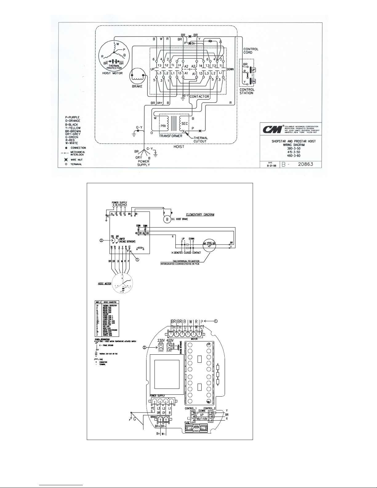
Figure 21 - 380-3-50, 415-3-50, 460-3-60 Hoists with Contactor (Black Control Station)
Figure 22 - 230-3-60, 400-3-50 PCB (Printed Circuit Board) Unit
21
P/N 192047138 Rev AA November 2017
Page 22

Figure 23 - 575-3-60 Hoists with Contactor (Black Control Station)
22
P/N 192047138 Rev AA November 2017
Page 23

DISASSEMBLY-ASSEMBLY
When disassembling and assembling the Shopstar Hoist, refer to
the exploded view and the parts list on pages 15 through 18.
These show the proper relationship of the parts, the names of the
parts and the required quantities of the parts. In addition, please
observe the following:
1. Needle bearings are pressed into the gear housing, main
frame, liftwheel and lower sheave wheel. Unless they are to
be replaced, do not attempt to remove these bearings.
2. A liftwheel seal is pressed into the main frame and a seal
is pressed into the end of the liftwheel shaft. Be careful
that these seals are not cut or damaged during disassembly
and reassembly.
Figure 24 - Main Frame
3. Refer to page 13 for disassembly, inspection, reassembly
and adjustment of the brake.
4. Do not attempt to disassemble the Protector™ - refer to
page 13.
5. Refer to page 14 for lubrication instructions.
6. See next section for load chain removal and installation.
7. Tighten the various screws as follows:
Table 6 - Torque Settings
Part Name
Pin Retainer Plate Screw 25 2.8
Motor Cover Screw 25 2.8
Gear Housing Screw 25 2.8
Brake End Cover Screw 25 2.8
Dead End Plate Screw 125 14.1
Hook Retainer Screw 10 1.1
Hook Block Screw, Double-reeved, 500,
600 and 1,000 lb (226, 272 and 453 kg)
Hook Block Screw, Single-reeved, 250,
300 and 500 lb (113, 136 and 226 kg)
Power Cord Ground Screw 20 2.2
8. When removing the stator , rst remove the brake end cover.
Disconnect stator leads from the wiring or contactor. At the
other end, remove the motor end cover. On single phase
units, use an insulated screw driver to short between the bare
terminals of the capacitor to discharge it. A spark may be
produced. Disconnect wiring to the capacitor and then remove
the capacitor. Remove the cut-out device and disconnect the
wires from it. Remove the rotor assembly and thrust washer.
Then slide the stator out of the main frame.
Seating
lb·in
Torque (N·m)
125 14.1
50 5.6
Pin Retainer Plate
Wire
Slot
Figure 25 - Stator Installation
9. To install the stator, (Refer to Figure 24) and make sure that the
pin retainer plate has been assembled to the main frame. On
single phase units slide jumpers “2” and “CAP” through the
wire slot in the main frame. Route these wires around the rotor
bearing boss in the main frame as shown in Figure 25. Attach
the brown and blue stator leads and “2” jumper to cut-out
device (refer to wiring diagram). Slide the cut-out device into
the cavity as shown. Push the cut-out device down until it sets
on the main frame. Place the capacitor on top of the cut-out
device and attach “CAP” jumper and the yellow stator lead to
it. Re-route jumpers “2” and “CAP”, if necessary to make sure
they clear the rotor bearing boss as shown in Figure 25. On all
units slide stator leads through wire slot. Align the slots in the
stator shell with the threaded holes in the main frame, as shown
in Figure 24. With the leads down, slide the stator into the main
frame. Slide the rotor, large bearing rst, into stator. Place
the rotor thrust washer on top of the exposed rotor bearing
and then assemble the motor end cover to the main frame.
Using wiring diagram, complete the wiring at the brake
end of the unit.
10. Properly install the upper hook as shown in Figure 27, then
slide the hook retainer into the cavity on top of the hoist and
secure it using hook retainer screw. Tighten screw to a seating
torque of 10 in. lbs. (1.1 NM).
LOAD CHAIN REMOVAL/INSTALLATION
1. If unit has a chain container, remove it from the chain guide.
2. Remove the chain stop. Depress DOWN button and run chain
out of hoist.
Figure 26: Chaining Hoist
23
P/N 192047138 Rev AA November 2017
Page 24

3. Feed a short length of soft wire through the opening in the
3. Feed a short length of soft wire through the opening in the
chain guide/stripper until it comes out of the hoist. Attach
“new” chain to end of the wire which is in the center of the
hoist. Position the chain so that the welds will be down and
towards the liftwheel as shown above in Figure 26.
4. Jog the UP push button while pulling on the free end of wire
until the chain comes out of the hoist. Remove the wire and
attach the chain stop as shown in Figure 28. On units with
chain container, place chain stop and loose end of chain in
chain container. Attach chain container to chain guide.
5. On the 250, 300 and 500 lbs (single reeved), (113, 136 and 226
kg) units, remove the hook block from the old chain and attach
it to the new chain by reusing the chain pin. On the 500, 600
and 1000 lbs (226, 272 and 453 kg) units:
out of dead end plate.
around the sheave wheel with welds down and towards the
sheave wheel.
hook block.
dead end pin.
• Making sure the chain is not twisted between the hook block and
hoist, attach the dead end plate to the chain guide/stripper.
• Retrace the new chain and check for twists. If chain is twisted,
start over.
IMPORTANT: Do not use “old” chain for other purposes such as
lifting or pulling. Load chain may break suddenly without visual
deformation. For this reason, cut the “old” chain into short lengths
to prevent use after disposal.
CUTTING CHAIN
Figure 29 - Cutting Chain by Nicking
Hoistaloy® load chain ishardened and it is difcult to cut. The
following methods are recommended when cutting a length of
new chain from stock or cutting off worn chain. Always wear eye
protection when cutting chain.
1. Use a grinder and nick the link on both sides (see right), then
secure the link in a vise and break off with a hammer.
2. Use a 7” (177 mm) minimum diameter by 1/8” (3.1 mm) thick
abrasive wheel (or type recommended by wheel supplier) that
will clear adjacent links.
Figure 30 - Cutting Chain with a Bolt Cutter
chain guide/stripper until it comes out of the hoist. Attach
“new” chain to end of the wire which is in the center of the
hoist. Position the chain so that the welds will be down and
towards the liftwheel as shown above in Figure 26.
4. Jog the UP push button while pulling on the free end of wire
until the chain comes out of the hoist. Remove the wire and
attach the chain stop as shown in Figure 28. On units with
chain container, place chain stop and loose end of chain in
chain container. Attach chain container to chain guide.
5. On the 250, 300 and 500 lbs (single reeved), (113, 136 and 226
kg) units, remove the hook block from the old chain and attach
it to the new chain by reusing the chain pin. On the 500, 600
and 1000 lbs (226, 272 and 453 kg) units:
• Remove dead end plate from hoist.
• Remove dead end pin from the last link of chain and pull chain
out of dead end plate.
• Pull old chain out of hook block and disassemble the hook block.
• Make sure the new chain is not twisted and wrap the chain
around the sheave wheel with welds down and towards the
sheave wheel.
• Reassemble hook block and pull the new chain through the
hook block.
• Slide the dead end plate over the last link and secure it using the
dead end pin.
Hook Opening
Away From
Loose End
Hook
Opening
Towards
Loose End
• Making sure the chain is not twisted between the hook block and
hoist, attach the dead end plate to the chain guide/stripper.
• Retrace the new chain and check for twists. If chain is twisted,
start over.
IMPORTANT: Do not use “old” chain for other purposes such as
lifting or pulling. Load chain may break suddenly without visual
deformation. For this reason, cut the “old” chain into short lengths
to prevent use after disposal.
CUTTING CHAIN
Figure 29 - Cutting Chain by Nicking
Hoistaloy® load chain ishardened and it is difcult to cut. The
following methods are recommended when cutting a length of
new chain from stock or cutting off worn chain. Always wear eye
protection when cutting chain.
1. Use a grinder and nick the link on both sides (see right), then
secure the link in a vise and break off with a hammer.
2. Use a 7” (177 mm) minimum diameter by 1/8” (3.1 mm) thick
abrasive wheel (or type recommended by wheel supplier) that
will clear adjacent links.
ShopStar
ShopStar
Loose
End
Figure 27 - Chaining Diagram
Loose
End
Figure 30 - Cutting Chain with a Bolt Cutter
Cutting chain can produce ying particles.
TO AVOID HEALTH PROBLEMS:
• Wear eye protection.
• Place a shield over chain to prevent ying objects.
3. Use a bolt cutter (see right) with special cutter jaws for cutting
hardened chain. Jaws should be 1 inch (25.4 mm) long.
TESTING
Before using, all altered, repaired or used hoists that have not been
operated for the previous 12 months must be tested by the user for
proper operation. First, test the unit without a load and then with a
light load of 50 pounds (23 kg) times the number of load supporting
parts of load chain to be sure that the hoist operates properly and
that the brake holds the load when control is released. Next test with
a load of *125% of rated capacity. In addition hoists in which load
sustaining parts have been replaced should be tested with *125% of
rated capacity by or under the direction of an appointed person and
written report prepared for record purposes. After this test, check
that the Protector functions. If the Protector permits lifting a load in
excess of 200% of rated load, it should be replaced.
*If the Protector prevents lifting of a load of 125% of rated capacity,
reduce load to rated capacity.
Figure 28 - Chain Stop
24
P/N 192047138 Rev AA November 2017
Page 25

REPAIR PARTS LIST
Using “Commercial” or other manufacturer’s parts to repair the CM
Shopstar Hoists may cause load loss.
TO AVOID INJURY
Use only CM supplied replacement parts. Parts may look alike but
CM parts are made of specic materials or processed to achieve
specic properties.
ORDERING INSTRUCTIONS
The following information must accompany all correspondence
orders for replacement parts:
1. Hoist Model Number from identication plate.
2. Serial number of the hoist stamped below identication plate.
3. Voltage, phase, hertz from the identication plate.
4. Length of lift.
5. Part number of part from parts list.
6. Number of parts required.
7. Part name from parts list.
Note
When ordering replacement parts, it is recommended that
consideration be given to the need for also ordering such items as
gaskets, fasteners, insulators, etc. These items may be damaged
or lost during disassembly or just unt for future use because of
deterioration from age or service.
RECOMMENDED SPARE PARTS
To insure continued service of the Shopstar Hoist, the following is a
list of parts that are recommended to be kept on hand at all times to
replace parts that have worn or failed. Parts applicable to your hoist
should be stocked.
Part Name Part Quantity
Contact manufacturer Brake field assem. 1
20698 Brake disc 1
Contact manufacturer Capacitor 1
20709 Cut-out device 1
Contact manufacturer Transformer 1
Contact manufacturer Reversing contactor 1
Contact manufacturer Control station 1
Contact manufacturer Control station parts kit 1
25
P/N 192047138 Rev AA November 2017
Page 26

SHOPSTAR MAIN ASSEMBLY
28
37
3
25
36
31
34
10
23
42
2
8
24
21
6
43
17
20
19
26
32
23
15
19
1
18
33
4
20
7
18
13
11
14
35
9
12
5
22
30
29
23
40
41
45
45
16
39
38
26
P/N 192047138 Rev AA November 2017
Page 27

SHOPSTAR MAIN ASSEMBLY
74
75
79
78
76
80
81
73
82
83
74
66
75
67
68
69
HOIST WITH CONTACTOR
SHOPSTAR MAIN ASSEMBLY
HOIST WITH PRINTED CIRCUIT BOARD
27
P/N 192047138 Rev AA November 2017
Page 28
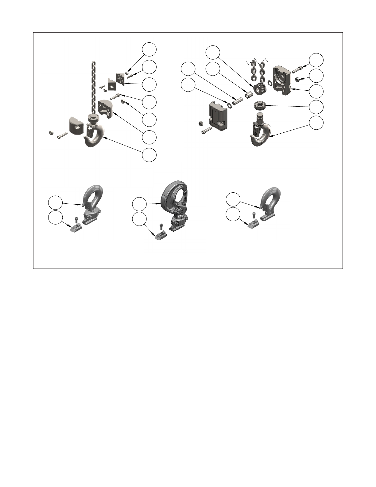
LOWER HOOK ASSEMBLIES
62
63
SWIVEL LATCHLOK
ASSEMBLY
64
63
51
60
61
48
47
49
46
SINGLE REEVED LOWER
HOOK & BLOCK
RIGID HOOK SUSPENSION
ASSEMBLY
65
63
DOUBLE REEVED LOWER
HOOK & BLOCK
56
54
60
61
55
59
58
57
53
SWIVEL HOOK SUSPENSION
ASSEMBLY
ITEM NO.
28
P/N 192047138 Rev AA November 2017
Page 29

SHOPSTAR PARTS LIST
ITEM
NO.
PART
NUMBER
DESCRIPTION QTY.
1 20704 LIFTWHEEL SHAFT SEAL 1
2 20723 BRAKE SPACER 1
BRAKE END COVER
20323 BRAKE END COVER - ORANGE 1
3
20377 BRAKE END COVER - WHITE 1
20366 BRAKE END COVER - YELLOW 1
4 20313 LIFTWHEEL SHAFT 1
MOTOR END COVER
20302 MOTOR END COVER - ORANGE 1
5
20356 MOTOR END COVER - WHITE 1
20369 MOTOR END COVER - YELLOW 1
GEAR HOUSING
20350 GEAR HOUSING - ORANGE 1
6
20371 GEAR HOUSING -WHITE 1
20368 GEAR HOUSING - YELLOW 1
MAIN FRAME
20352 MAIN FRAME - ORANGE 1
7
20370 MAIN FRAME - WHITE 1
20367 MAIN FRAME - YELLOW 1
8 20419 BRAKE BASE PLATE 1
9 20651 ROTOR ASSEMBLY 1
10 20698 BRAKE DISC 1
11 20700 PIN RETAINER PLATE 1
12 20727 ROTOR THRUST WASHER 1
13 20729 CHAIN GUIDE/STRIPPER PIN 4
14 20743 PIN RETAINER PLATE SCREW 2
15 20755 GASKET 1
16 20758 CAUTION LABEL 1
17 24842 WARNING LABEL 2
18 88638 LIFTWHEEL THRUST WASHER 2
19 88639 FIRST PINION THRUST WASHER 2
20 88640 PROTECTOR THRUST WASHER 2
21 920718 GEAR HOUSING SCREW 4
22 920719 MOTOR COVER SCREW 3
23 920720 DOWEL PIN 4
24 920756 WIRE NUT *
25 10001215 BRAKE SCREW 4
CAPACITY WARNING LABEL
20762 CAPACITY WARNING LABEL - 250 lbs. 1
20737 CAPACITY WARNING LABEL - 300 lbs. 1
26
20763 CAPACITY WARNING LABEL - 500 lbs. 1
20738 CAPACITY WARNING LABEL - 600 lbs. 1
20884 CAPACITY WARNING LABEL - 1,000 lbs. 1
CHAIN GUIDE/STRIPPER
10001230 SINGLE PIECE CHAIN GUIDE/STRIPPER 1
27
20304/
20305
INDIVIDUAL CHAIN GUIDE/STRIPPER 1
ITEM
NO.
PART
NUMBER
DESCRIPTION QTY.
HOIST LABEL
20753 SERIES LABEL (SHOPSTAR) 1
20874 SERIES LABEL (SHOPHOIST) 1
28
20901 SERIES LABEL (SLC) 1
20903 SERIES LABEL (SLM) 1
29 20887 BRAKE SPRING 1
30 20422 FIRST PINION & DRIVE SHAFT 1
LIFTWHEEL AND GEAR ASSEMBLY
20666 LIFTWHEEL AND GEAR ASSEMBLY - 6 fpm, 1,000 lbs. 1
20664
LIFTWHEEL AND GEAR ASSEMBLY - 8 fpm, 500,
600 & 1,000 lbs.
20666 LIFTWHEEL AND GEAR ASSEMBLY - 12 fpm, 500 lbs. 1
20647
31
20664
20657
20647
20657
LIFTWHEEL AND GEAR ASSEMBLY - 12 fpm, 600
& 1000 lbs.
LIFTWHEEL AND GEAR ASSEMBLY - 16 fpm, 250,
300 & 500 lbs.
LIFTWHEEL AND GEAR ASSEMBLY - 20 fpm, 500
& 600 lbs.
LIFTWHEEL AND GEAR ASSEMBLY - 24 fpm, 250,
300 & 500 lbs.
LIFTWHEEL AND GEAR ASSEMBLY - 40 fpm, 250
& 300 lbs.
32 20420 BRAKE ARMATURE 1
STATOR
20707 STATOR - 115-1-50/60 HOISTS 1
20328 STATOR - 220-1-50 HOISTS 1
20329 STATOR - 220-3-50/60 HOISTS 1
33
20330
STATOR - 380-3-50, 415-3-50 & 460-3-60
HOISTS
20344 STATOR - 575-3-60 HOISTS 1
192039309 STATOR - 220/230-3-50/60 WITH PCB 1
192039311 STATOR 380-3-50, 400-3-50, 415-3-50 WITH PCB 1
BRAKE FIELD (INCLUDES BRAKE COIL)
20659
BRAKE FIELD (INCLUDES BRAKE COIL) -
115-1-50/60 HOISTS
BRAKE FIELD (INCLUDES BRAKE COIL) -
20658
34
20629
220-1-50, 220-3-50/60, 380-3-50, 415-3-50 &
460-3-60 HOISTS
BRAKE FIELD (INCLUDES BRAKE COIL) - 575-3-60
HOISTS
192039344 BRAKE FIELD - PCB 1
BRAKE END COVER SCREW
920715
35
20808
BRAKE END COVER SCREW - HOISTS WITHOUT
CONTACTOR
BRAKE END COVER SCREW - HOISTS WITH
CONTACTOR
CUT-OUT DEVICE
36
20709 CUT-OUT DEVICE - 115-1-50/60 HOISTS 1
20786 CUT-OUT DEVICE - 220-1-50, 230-1-60 HOISTS 1
CAPACITOR
37
20708 CAPACITOR - 115-1-50/60 HOIST 1
20785 CAPACITOR - 220-1-50 HOIST 1
38 20714 DEAD END PLATE (DOUBLE CHAINED) 1
1
1
1
1
1
1
1
1
1
1
3
3
29
P/N 192047138 Rev AA November 2017
Page 30

ITEM
NO.
PART
NUMBER
DESCRIPTION QTY.
39 73715 DEAD END PLATE SCREW (DOUBLE CHAINED) 2
40 20717 POWER CORD GROMMET (NOT SHOWN) 1
POWER CORD
20635
20608
POWER CORD - 115-1-50/60 HOISTS WITH
CONTACTOR
POWER COR - 115-1-50/60 HOISTS WITHOUT
CONTACTOR
20633 POWER CORD - 220-1-50 HOISTS 1
41
30628
POWER CORD - 220-3-50/60, 380-3-50, 415-3-
60, 460-3-60 & 575-3-60 HOISTS
192039303 PCB POWER CORD - “SHORT” 3’ 1
23657605 PCB POWER CORD - 5’ - FOR 10’ LIFT 1
23657610 PCB POWER CORD - 10’ - FOR 15’ LIFT 1
23657615 PCB POWER CORD - 15’ - FOR 20’ LIFT 1
42 20711 CONTROL CORD GROMMET (NOT SHOWN) 1
43 ** CONTROL STATION A/R
PROTECTOR ASSEMBLY1
20665 PROTECTOR ASSEMBLY - 6 fpm, 1,000 lbs. 1
20645 PROTECTOR ASSEMBLY - 8 fpm, 500 & 600 lbs. 1
20660 PROTECTOR ASSEMBLY - 8 fpm, 1000 lbs. 1
20665 PROTECTOR ASSEMBLY - 12 fpm 500 lbs. 1
20638 PROTECTOR ASSEMBLY - 12 fpm, 600 lbs. 1
20662 PROTECTOR ASSEMBLY - 12 fpm, 1000 lbs. 1
20645 PROTECTOR ASSEMBLY - 16 fpm, 500 lbs. 1
44
20660 PROTECTOR ASSEMBLY - 16 fpm, 500 lbs. 1
20648 PROTECTOR ASSEMBLY - 20 fpm, 500 lbs 1
20661 PROTECTOR ASSEMBLY - 20 fpm, 600 lbs. 1
20638 PROTECTOR ASSEMBLY - 24 fpm, 250 & 300 lbs 1
20662 PROTECTOR ASSEMBLY - 24 fpm, 500 lbs. 1
20648 PROTECTOR ASSEMBLY - 40 fpm, 250 lbs 1
20661 PROTECTOR ASSEMBLY - 40 fpm, 300 lbs. 1
CONTROL CORD ASSEMBLY
CONTROL CORD ASSEMBLY - ORANGE CONTROL
STATION 10 ft. lift
CONTROL CORD ASSEMBLY - ORANGE CONTROL
STATION 15 ft. lift
CONTROL CORD ASSEMBLY - ORANGE CONTROL
STATION 20 ft. lift
CONTROL CORD ASSEMBLY - BLACK CONTROL
STATION 10 ft. lift
CONTROL CORD ASSEMBLY - BLACK CONTROL
STATION 15 ft. lift
CONTROL CORD ASSEMBLY - BLACK CONTROL
STATION 20 ft. lift
CONTROL CORD ASSEMBLY - PCB CONTROL -
Short 3' cord
CONTROL CORD ASSEMBLY - PCB CONTROL - 6'
- 10' lift
CONTROL CORD ASSEMBLY - PCB CONTROL -
11' - 15' lift
CONTROL CORD ASSEMBLY - PCB CONTROL
16' - 20' lift
CONTROL CORD ASSEMBLY - CM ROCKET
PENDANT - 10' lift
CONTROL CORD ASSEMBLY - CM ROCKET
PENDANT - 15' lift
CONTROL CORD ASSEMBLY - CM ROCKET
PENDANT - 20' lift
45
20667
20668
20669
20675
20676
20677
192039304
23658206
23658211
23658216
23654206
23654211
23654216
ITEM
NO.
PART
NUMBER
46 10001931 LATCH TYPE HOOK ASSEMBLY 1
47 10001878 LOWER HOOK BLOCK (1 REEVE) 2
48 82554 CAP SCREW, SOCKET HEAD 2
1
49 82638 HOOK BLOCK NUT (1 REEVE) 2
50 20428 CHAIN STOP 2
1
51 25848 CHAIN STOP SCREW 2
52 982472 CHAIN STOP NUT 2
1
53 10001932 LATCHLOK HOOK ASSEMBLY - SWIVEL (2 REEVE) A/R
54 10001927 HOOK BLOCK (2 REEVE) 2
55 670132 WEDGE RING (2 REEVE) 1
56 82554 HOOK BLOCK CAP SCREW (2 REEVE) 2
57 82638 HOOK BLOCK NUT (2 REEVE) 2
58 88639 THRUST WASHER (2 REEVE) 2
59 20318 SHEAVE WHEEL SHAFT (2 REEVE) 1
60 20316 SHEAVE WHEEL (2 REEVE) 1
61 88641 BEARING - SHEAVE WHEEL (2 REEVE) 1
62 20650 LATCH HOOK ASSEMBLY RIGID A/R
63 20713K HOOK RETAINER & SCREW 1
64 574303 LATCHLOK HOOK ASSEMBLY SWIVEL A/R
65 10001130 LATCH HOOK ASSEMBLY SWIVEL A/R
20333C FRAME SPACER - ORANGE 1
66
20333W FRAME SPACER - WHITE 1
20333Y FRAME SPACER - YELLOW 1
67 SEE ITEM NO. 78
68 20781 POWER CORD PLUG 1
69 20780 PLUG, CONTROL CORD 1
10001998 PCB - 48V 1
70
10001999 PCB - 110V 1
71 10001979 PCB RETAINER 1
72 20777 OUTBOARD COMPONENT BRACKET 1
73 20778 INBOARD COMPONENT 1
20787 CONTACTOR 48V 1
74
20814 CONTACTOR 110V 1
75 20789 DIODE S/A 1
76 20851 TRANSFORMER 1
77 20861 VOLTAGE SUPPERSSOR 1
78 20808 MOTOR COVER SCREW 3
79 20781 POWER CORD PLUG 1
80 20780 PLUG, CONTROL CORD 1
81 *** JUMPERS A/R
A/R - As Requested - Contact Factory.
* Quantity is application dependent.
** See Control Station Section.
*** Contact Factory for Jumpers based on application.
30
DESCRIPTION QTY.
FRAME SPACER
P/N 192047138 Rev AA November 2017
Page 31

CONTROL STATIONS
CONTROL STATION (ORANGE) FOR USE ON 115 1-50/60
HOISTS WITHOUT CONTACTOR
PARTS LIST
Key No. No. Part Name Required Part Number
620-186
Control station with retainer,
screws and grommet
1 24807
CONTROL STATION (BLACK) FOR USE ON 115-1-50/60
HOISTS WITH CONTACTOR, 220-1-50 AND THREE
PHASE UNITS
CONTROL STATION
Key No. No. Part Name Required Part Number
624-232
Control Station (Includes
624-301 thru 624-307)
1 36900B
624-252 Warning Label (Electrical) 1 24842
624-253 Manufacturer Label 1 28470
624-301 Control Station Grommet 1 36989
624-302 Control Station Housing 1 36998B
624-303 Gasket 1 36986
624-304
624-306 Control Station Parts Kit 1 36939
624-307
624-308 Warning Label 1 24845
31
Control Station Button
Assembly
Contact Assembly
(Includes 624-304)
1 36988
1 36987
P/N 192047138 Rev AA November 2017
Page 32

CM ROCKET UNIVERSAL PENDANT
23
20
6
*
**
13
16
27
1929
1627
12
2829
3
24***
2
17 27
14
10
7
25
5
* Enclosure Top with
** Strain Relief Plate
26****
E-stop Hole
13
24
Rocket Universal Pendant Control
Product Code Description
ECUR-1S Rocket Pendant Control - Single-Speed, No E-stop
ECUR-1SE Rocket Pendant Control - Single-Speed with E-stop
ECUR-2S Rocket Pendant Control - 2-Speed, No E-stop
ECUR-2SE Rocket Pendant Control - 2-Speed with E-stop
ECUR-1S-25P 25 PACK: Rocket Pendant Control - Single-Speed, No E-stop
ECUR-1SE-25P 25 PACK: Rocket Pendant Control - Single-Speed with E-stop
ECUR-2S-25P 25 PACK: Rocket Pendant Control - 2-Speed, No E-stop
ECUR-2SE-25P 25 PACK: Rocket Pendant Control - 2-Speed with E-stop
6
1929
15 18
*** 2-Speed Pendants
include 4 Switches
24
Product Code Description Qty
ECUR-0001 Strain Relief Kit 1
ECUR-0010 Switch Repair Kit, 2-Speed, 4 Switch 1
ECUR-0011 Switch Repair Kit, Single-Speed, 2 Switch 1
ECUR-0020 Enclosure Repair Kit, No E-Stop 1
ECUR-0021 Enclosure Repair Kit, With E-Stop 1
ECUR-0030 Label Kit 1
23608124 Emergency Stop Push Button 1
23608110 Rocket Bushing CBL 13.3-16.5mm 1
4
**** Screw Terminal Strip
26
Replacement Parts
32
P/N 192047138 Rev AA November 2017
Page 33

NOTES
33
P/N 192047138 Rev AA November 2017
Page 34

WARRANTY
LIMITATION OF WARRANTIES, REMEDIES AND DAMAGES
INDEMNIFICATION AND SAFE OPERATION
Buyer shall comply with and require its employees to comply with directions set
forth in instructions and manuals furnished by Seller and shall use and require its
employees to follow such instructions and manuals and to use reasonable care in
the use and maintenance of the goods. Buyer shall not remove or permit anyone
to remove any warning or instruction signs on the goods. In the event of personal
injury or damage to property or business arising from the use of the goods,
Buyer shall within 48 hours thereafter give Seller written notice of such injury
or damage. Buyer shall cooperate with Seller in investigating any such injury or
damage and in the defense of any claims arising therefrom.
If Buyer fails to comply with this section or if any injury or damage is caused,
in whole or in part, by Buyer’s failure to comply with applicable federal or state
safety requirements, Buyer shall indemnify and hold Seller harmless against any
claims, loss or expense for injury or damage arising from the use of the goods.
CMCO Warranty (HOISTS)
A. Columbus McKinnon Corporation (“Seller”) warrants to the original end
user (“Buyer”) that: (a) for a period of one (1) year from the date of Seller’s
delivery of the goods (collectively, the “Goods”) to the carrier, the electrical
components of the Goods will be free from defects in workmanship and
materials; and (b) for the life of the Goods, the mechanical components of the
Goods will be free from defects in workmanship and materials.
B. IN THE EVENT OF ANY BREACH OF SUCH WARRANTY, SELLER’S SOLE
OBLIGATION SHALL BE EXCLUSIVELY LIMITED TO, AT THE OPTION OF
SELLER, REPAIR OR REPLACEMENT, F.O.B. SELLER’S POINT OF SHIPMENT,
OF ANY GOODS THAT SELLER DETERMINES TO HAVE BEEN DEFECTIVE
OR, IF SELLER DETERMINES THAT SUCH REPAIR OR REPLACEMENT IS NOT
FEASIBLE, TO A REFUND OF THE PURCHASE PRICE UPON RETURN OF THE
GOODS TO SELLER. NO CLAIM AGAINST SELLER FOR ANY BREACH OF (i)
SUCH WARRANTY WITH RESPECT TO THE ELECTRICAL COMPONENTS OF
ANY GOOD SHALL BE VALID OR ENFORCEABLE UNLESS BUYER’S WRITTEN
NOTICE THEREOF IS RECEIVED BY SELLER WITHIN ONE (1) YEAR FROM THE
DATE OF SELLER’S DELIVERY TO THE CARRIER AND (ii) SUCH WARRANTY
WITH RESPECT TO THE MECHANICAL COMPONENTS OF ANY GOOD SHALL
BE VALID OR ENFORCEABLE UNLESS BUYER’S WRITTEN NOTICE THEREOF
IS RECEIVED BY SELLER WITHIN ONE (1) YEAR FROM THE DATE THE DATE
ANY ALLEGED CLAIM ACCRUES. EXCEPT FOR THE WARRANTY SET FORTH
ABOVE, SELLER MAKES NO OTHER WARRANTIES WITH RESPECT TO THE
GOODS, WHETHER EXPRESSED OR IMPLIED, INCLUDING ANY WARRANTIES
OF MERCHANTABILITY, FITNESS FOR A PARTICULAR PURPOSE, QUALITY
AND/OR THOSE ARISING BY STATUTE OR OTHERWISE BY LAW OR FROM
ANY COURSE OF DEALING OR USE OF TRADE, ALL OF WHICH ARE HEREBY
EXPRESSLY DISCLAIMED.
C. IN NO EVENT SHALL SELLER BE LIABLE TO BUYER OR ANY THIRD PARTY
WITH RESPECT TO ANY GOOD, WHETHER IN CONTRACT, TORT OR
OTHER THEORY OF LAW, FOR LOSS OF PROFITS OR LOSS OF USE, OR
FOR ANY INCIDENTAL, CONSEQUENTIAL, SPECIAL, DIRECT OR INDIRECT
DAMAGES, HOWSOEVER CAUSED. SELLER’S MAXIMUM LIABILITY TO
BUYER WITH RESPECT TO THE GOODS SHALL IN NO EVENT EXCEED THE
PRICE PAID BY BUYER FOR THE GOODS THAT ARE THE SUBJECT OF THE
APPLICABLE CLAIM.
D. Seller shall not be liable for any damage, injury or loss arising out of the use of
the Goods if, prior to such damage, injury or loss, such Goods are: (1) damaged
or misused following Seller’s delivery to the carrier; (2) not maintained, inspected,
or used in compliance with applicable law and Seller’s written instructions
and recommendations; or (3) installed, repaired, altered or modied without
compliance with such laws, instructions or recommendations.
E. This warranty is limited and provided only to the original end user. Each Good
must be registered within sixty (60) days of receipt of each product to
establish eligibility. Please register at www.cmworks.com/hoist-warranty-
registration or submit registration card via US mail.
F. Any action against Seller for breach of warranty, negligence or otherwise in
connection with the electrical components of any Good must be commenced
by Buyer within one (1) year after: (a) the date any alleged claim accrues; or
(b) the date of delivery of the Goods to Buyer, whichever is earlier. Any action
against Seller for breach of warranty, negligence or otherwise in connection
with the mechanical components of any Good must be commenced by Buyer
within one (1) year after the date any alleged claim accrues.
Alterations or modifications of equipment and use of non-factory repair
parts can lead to dangerous operation and injury.
TO AVOID INJURY:
• Do not alter or modify equipment.
• Do use only factory replacement parts.
USA: Ph: (800) 888.0985 • (716) 689.5400 • Fax: (716) 689.5644 • www.cmworks.com
CANADA: Ph: (877) 264.6478
© 2017 Columbus McKinnon Corporation. All Rights Reserved.
•
Fax: (877) 264.6477 • www.cmworks.com
P/N 192047138 Rev AA November 2017
 Loading...