

Page 1
c
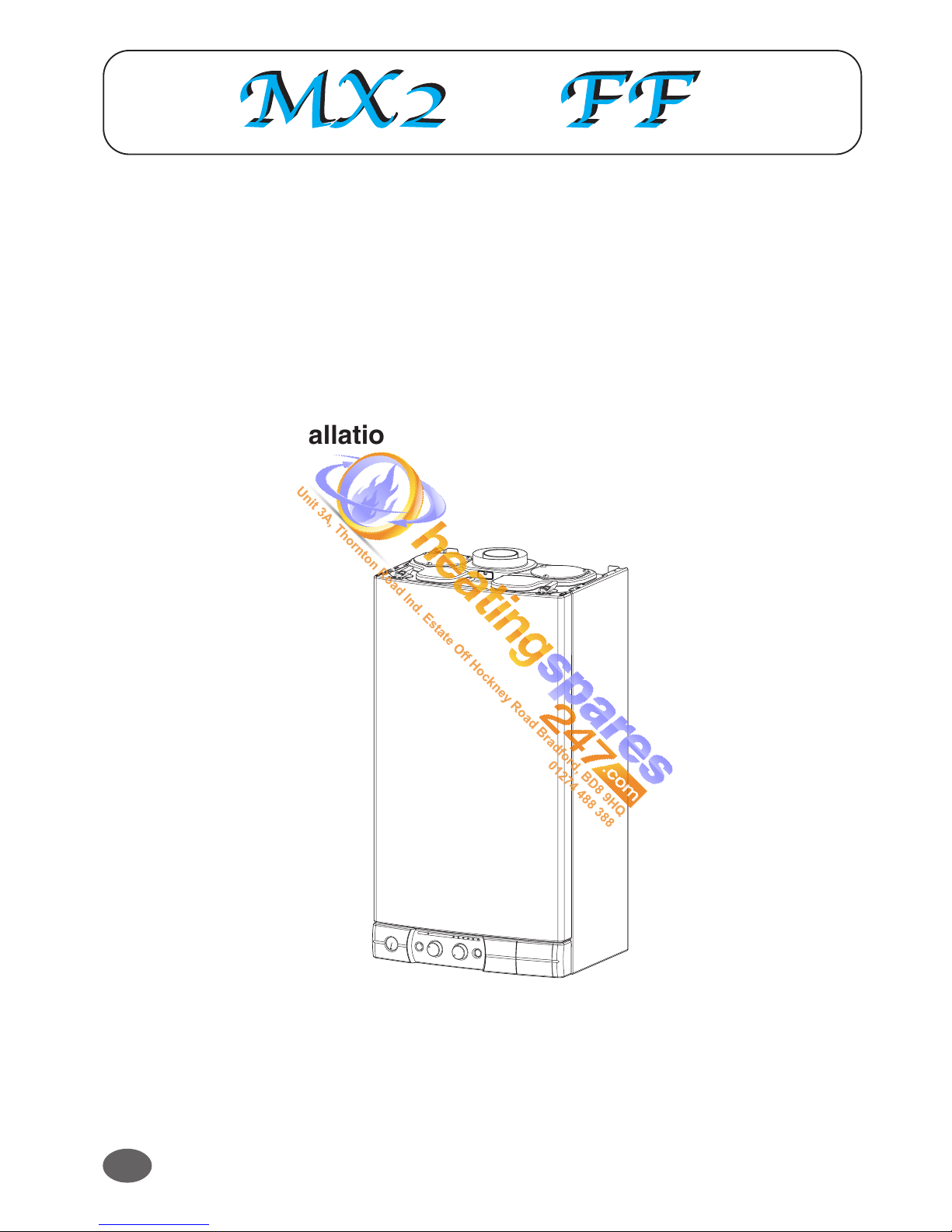
COMBINATION BOILER
Heating and Instantaneous Domestic Hot Water
Fanned Flue system
Installation and Operating instructions
Manufactures N° Model Type Gas Council N°
200906827037.31 MX2 24 Nat 47 - 980 - 28
200906828037.31 MX2 30 Nat 47 - 980 - 29
GB
Unit 3A, Thornton Road Ind. Estate Off Hockney Road Bradford, BD8 9HQ
01274 488 388
Page 2
2
These instructions are suitable for the NC boilers :
Do not forget the Logbook!
Chaffoteaux & Maury supports Benchmark, the heating industry code to ensure the correct installation, commissioning and
servicing of domestic central heating systems.
To The Householder
Make sure you have a completed Logbook for your boiler. This provides a record of the commissioning of your boiler.
It contains important information about your particular installation that may be required by service engineers. The logbook will
also provide contact details for the installer should you need guidance in the use of this appliance or if there are any problems.
As with your car, your boiler will work more reliably and efficiently if regularly serviced. We recommend an annual service
check. The service history of the appliance will be recorded on the logbook.
In the unlikely event of any problems with your boiler or system you should first contact your installer. If your installer cannot
resolve the problem he should telephone our national service helpline.
A charge may be made if Chaffoteaux & Maury Service is called out to resolve a non-product related fault.
Your statutory rights are not affected.
CUSTOMER CARE
Chaffoteaux & Maury Ltd., as a leading manufacturer of domestic and commercial water heating appliances is committed to
providing high quality products and a high quality after sales service. If it is necessary to contact an engineer, then telephone
the national warranty helpline 0870 243 0224.
Advice on installation or servicing can also be obtained by contacting the Chaffoteaux Customer Services Department at
Telford.
CUSTOMER SERVICES DEPARTMENT
Tel: 01952 222288
Fax: 01952 260915
GUARANTEE
The manufacturer’s guarantee is for 12 months from the date of purchase. The guarantee is invalidated if the appliance is not
installed in accordance with the recommendations made herein or in a manner not approved by the manufacturer. To assist us
in providing you with an efficient after sales service, please return the guarantee registration card enclosed with the boiler
without delay.
STATUTORY REQUIREMENTS
The installation of this appliance must be carried out by a CORGI Registered person or other competent person and in
accordance with the requirements of the Gas Safety (Installation and Use) Regulations.
In addition, the installation must also comply with the current bylaws of Local Water Undertakings, Building Regulations, IEE
Wiring Regulations, Local Authority Building Standards (Scotland) Regulations and the Safety Document 635 The Electricity at
work Regulation. The appliance named below does not contain any asbestos or asbestos products, or mercury
derivatives. Additional CFC’s have not been used in this product.
The appliance does not contain any potential hazard in relation to the COSHH regulations.
It should also be carried out in accordance with current editions of the following British Standards Codes of practice: BS 6891,
BS 5440 parts 1 and 2, BS 5449 part 1, BS 7593, BS 6798, BS 5546, BS 4814, BS 7074 part 1 and 2, BS 7671 and BG DM2.
If there is a possibility of the incoming mains water pressure exceeding 10 bar then a suitable pressure limiting valve must be
fitted where pressures exceed 6 bars a pressure limiting is preferred.
Precautions: During servicing, keep the dust generation to a minimum and avoid inhaling any dust and contact with the skin
and eyes. Normal handling and use will not present any discomfort, although some people with a history of skin complaints
may be susceptible to irritation. When disposing of the ceramic lining, ensure that it is securely wrapped and wash hands after
contact.
TO CONTACT C&M SERVICE, PLEASE CALL THE NATIONAL WARRANTY HELPLINE ON:
0 870 243 0224
To The Installer
As part of the commissioning of this appliance it is vital that the Logbook is completed and given to the Householder. Please
ensure that your customer is aware of the importance of keeping the Logbook safe as a record of the installation and the
appliance service history.
Please ensure that your customer is aware of the correct operation of the system, boiler and controls.
Unit 3A, Thornton Road Ind. Estate Off Hockney Road Bradford, BD8 9HQ
01274 488 388
Page 3

3
Contents
CUSTOMER CARE
Page
Guarantee ............................................................................................................................................................2
Statutory Requirements .......................................................................................................................................2
Contents ...............................................................................................................................................................3
INSTALLER’S INSTRUCTION.............................................................................................................................5
1 DESCRIPTION ................................................................................................................................................5
2 DIMENSIONS .................................................................................................................................................6
3 HYDRAULIC DATA .........................................................................................................................................6
4 INSTALLATION REQUIREMENTS ................................................................................................................7
Location ...................................................................................................................................................7
Flue ..........................................................................................................................................................7
Ventilation ................................................................................................................................................7
Gas Supply .............................................................................................................................................7
Electrical Supply ....................................................................................................................................7
Showers ...................................................................................................................................................7
Flushing and Water Treatment ...............................................................................................................7
System Controls ......................................................................................................................................7
5 CONNECTING GAS INTAKE AND EXHAUST DUCTS ..................................................................................8
6 INSTALLING THE BOILER ...........................................................................................................................10
7 ELECTRICAL CONNECTIONS ....................................................................................................................11
8 OPERATING..................................................................................................................................................12
Pressurising ...........................................................................................................................................12
Settings ..................................................................................................................................................12
Burner gas output setting ......................................................................................................................13
9 FITTING THE CASING ..................................................................................................................................14
10 GAS CONVERSION ......................................................................................................................................15
11 INCORRECT FUNCTION .............................................................................................................................16
12 PARTICULAR CHARACTERISTICS ............................................................................................................17
Unit 3A, Thornton Road Ind. Estate Off Hockney Road Bradford, BD8 9HQ
01274 488 388
Page 4

4
USER’S INSTRUCTIONS
Page
13- CONTROL PANEL .......................................................................................................................................18
14- HOW TO USE ..............................................................................................................................................19
15 MAINTENANCE ............................................................................................................................................20
16 FLUE GAS SAFETY .....................................................................................................................................20
17 GUARANTEE ................................................................................................................................................20
18 PRACTICAL INFORMATION ........................................................................................................................20
19 TECHNICAL DATA .......................................................................................................................................21
20 INSTRUCTION FOR SETTING THE BUILT IN CLOCK................................................................................22
21 INCORRECT FUNCTION ..............................................................................................................................23
This instruction booklet is especially designed for appliances installed in United Kingdoms
INTRODUCTION
The
MX2 is a fully automatic, wall mounted, low water content combination boiler. It is a room sealed, fan
assisted, balanced flued appliance providing central heating and mains pressure domestic hot water on demand.
It has electronic ignition and is suitable for all modern electrical control systems. The boiler is designed for sealed
systems only and a circulating pump, expansion vessel together with a pressure gauge and safety valve are
included within the boiler.
The standard horizontal flue kit is suitable for lengths 300 mm minimum to 850 mm maximum and includes an
elbow adapter that can be rotated through 360 ° . The horizontal flue can extend up to 4 metres using 1 metre
flue extension kits. 45 ° and 90° flue bends are also available as accessories.
Unit 3A, Thornton Road Ind. Estate Off Hockney Road Bradford, BD8 9HQ
01274 488 388
Page 5
5
1
Description
INSTALLER’S INSTRUCTIONS
Fig.1
1
2
14
4
5
6
12
3
10
15
17
16
18
Fig.2
7
8
9
11
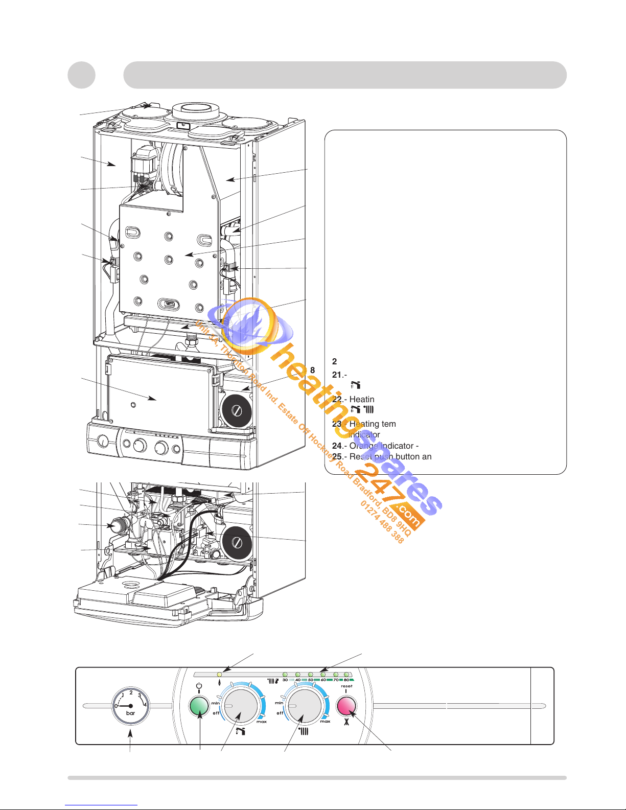
1.- Steel chassis complete with expansion vessel
2.- Sealed chamber
3.- Flue hood with fan
4.- Main heat exchanger
5.- Combustion chamber
6.- Multi- gas burner assembly comprising ignition and
ionisation electrodes
7.- Gas valve assembly
8.- Pump with automatic air separator and automatic vent
9.- Overheat safety cutout
10 - Main exchanger inlet thermistor
11.- Main exchanger outlet thermistor
12.- Electrical box
13.- Hot water flow sensor
14.- Air pressure switch
15.- Ignitor
16.- Central heating pressure relief valve
17.- Three way valve
18.- Secondary heat exchanger
19. - Pressure gauge
20. - On/off push button and power on indicator light
21.- Sanitary temperature setting and sanitary start button
22.- Heating temperature setting and heating start button
23.- Heating temperature indicator and operating faults
indicator
24.- Orange indicator - Burner ON
25.- Reset push button and red indicator locking light
13
20
21
23
25
22
24
19
Fig.3
c
Unit 3A, Thornton Road Ind. Estate Off Hockney Road Bradford, BD8 9HQ
01274 488 388
Page 6
6
440
450 mini pour entretien
Fig. 4
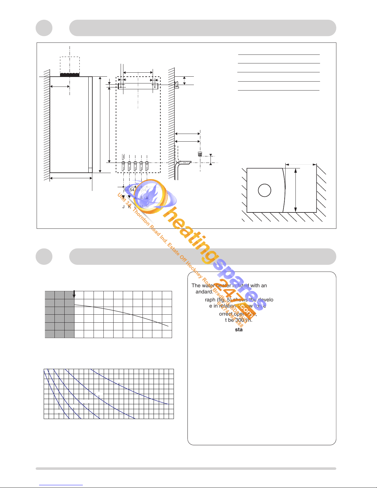
2 Dimensions
54 54 54 54
JKLMN
I
JKLMN
32
296
141
289
15
21
720
652
121,5
I
172,5
18,5
18
All dimensions in mm
With packaging :
24 kW : 32 kg
30 kW : 33 kg
3
Hydraulic data
Fig. 5
Fig. 6
The water heater is fitted with an automatic by-pass as
standard.
The graph (fig. 5) shows the developmentof the pressure
available in relation to flow (on exit from the boiler).
To ensure correct operation, the minimum flow of the
appliance must be 300 l/h. (Thermostatic taps closed).
Capacity of the installation.
The water heater is fitted with a pressurised expansion
vessel.
Maximum. volume of expansion vessel: 6 litres.
Pressure: 1 bar.
The volume of the expansion vessel in a pressurised
appliance varies according to:
- the average operating temperature in °C
- the static height, which is the difference in metres between
the highest point of the appliance and the expansion vessel
axis).
The minimum cold filling pressure of the appliance is 1 bar
(recommended pressure between 1.2 and 1.7 bar).
The pressure of the expansion vessel should always be
greater than the static height (in metres) divided by 10.
0
4
3
2
1
5
6
100
200 800
700
600
500
400
300
900
1000
1100
1200
l/h
mCE
Débit mini (robinets thermostatiques fermés)
Pression disponible
20 40 60 80 100 120
Pf
140 160 180 200 220 240
1,0
1,1
1,2
1,3
1,4
1,5
1,6
1,7
1,8
1,9
2,0
Capacité maximale de l'installation (en litres)
260
Pression à froid pour le circuit chauffage (en bar)
280
40°C
50°C
60°C
70°C
80°C
390
minimum space required 450
I Safety valve C/H and condensate
J
Heating flow
K
D.H.W. flow
L
Gas supply
M
Cold water inlet
N
Heating return
C liter
Pump head chart available at the outlet of the boiler
System capacity chart
Pump head available
Minimum flow rate (with all heating thermostatic valves closed)
Central heating initial pressure when cold (in bar)
Diagramme de contenance en eau.
Unit 3A, Thornton Road Ind. Estate Off Hockney Road Bradford, BD8 9HQ
01274 488 388
Page 7

7
4 Installation requirements
Location
The boiler can be installed on any suitable internal wall.
Provision must be made to allow the correct routing of the flue
and siting of the terminal to allow the safe and efficient
removal of the flue products. A compartment or cupboard may
be used provided that it has been purpose-built or modified for
the purpose. It is not necessary to provide permanent
ventilation for cooling purposes. Detailed recommendations
are given in BS 5440 pt 2. If it is proposed that it is installed in
a timber framed building then reference must be made to
British Gas Document DM2, or advice sought from CORGI.
Avoid to install the boiler where the air inlet can be polluted
by chemical products such as chlorine (swimming pool aera),
or ammonia (hair dresser), or alcalin products (launderette)
Flue
Detailed information on flue assembly is contained in the
appropriate starter pack.
The boiler must be installed so that the flue terminal is
exposed to the free passage of external air at all times. It must
not be allowed to discharge into another room or space such
as an outhouse or closed lean-to. The minimum acceptable
clearances are shown below:
- A Directly below an opening, window, etc 300 mm
- B Above an opening, window, etc 300 mm
- C Horizontally to an opening, window, etc 300 mm
- D Below gutters, soils pipes or drain pipes 75 mm
- E Below eaves 200 mm
- F Below balconies or car port roof 200 mm
- G From a vertical drain pipe or soil pipe 150 mm
- H From an internal or external corner 300 mm
- I Above ground roof or balcony level 300 mm
- J From a surface facing the terminal 600 mm
- K From a terminal facing the terminal 1200 mm
- L From an opening in the car port into the dwelling 1200 mm
- M Vertically from a terminal on the same wall 1500 mm
- N Horizontally from a terminal on the same wall 300 mm
- Q Fixed by Ubbink Rolux 4 GM flue terminal
It may be necessary to protect the terminal with a
guard. Reference should be made to the Building
Regulations for guidance. Suitable guards may be
obtained from the following manufacturer:
Quinnel Barret & Quinnel Wireworks
Old Kent Road
London SE15 1NL
Tel: 0171 639 1357
Ventilation
The room in which the boiler is installed does not require specific
ventilation. If it is installed in a cupboard or compartment
permanent ventilation is not required for cooling purposes.
Gas Supply
The gas installation and soundness testing must be in
accordance with the requirements of BS 6891.The boiler
requires a 22 mm supply. Ensure that the pipe size is
adequate for demand including other gas appliances on the
same supply.
Electrical Supply
The appliance requires an earthed 230V - 50 Hz supply and
must be in accordance with current I.E.E. It must also be
possible to be able to completely isolate the appliance
electrically. Connection should be via a 3 amp fused doublepole isolating switch with contact separation of at least 3 mm
on both poles. Alternatively, a fused 3 Amp. 3 pin plug and
unswitched socket may be used, provided it is not used in a
room containing a bath or shower. It should only supply the
appliance.
The boiler is suitable for sealed systems only. The maximum
working pressure for the appliance is 10 bar. All fittings and
pipework connected to the appliance should be of the same
standard. If there is a possibility of the incoming mains
pressure exceeding 10 bar, particularly at night, then a
suitable pressure limiting valve must be fitted.
The boiler is designed to provide hot water on demand to
multiple outlets within the property. If there is a requirement
for greater demands, for example if the property has several
bathrooms and cloakrooms, a vented or unvented hot water
storage system may be used.
Showers
Any shower valves used with the appliance should be of a
thermostatic or pressure balanced type. Refer to the shower
manufacturer for performance guidance and suitability.
Flushing and Water Treatment
The performance of the appliance could be impaired by
system debris or the effects of corrosion. The system must
be flushed thoroughly to remove metal filings, solder,
machining oils and other fluxes and greases before
connecting the boiler. If it is an existing system, an
appropriate flushing and descaling agent should be used.
Refer to BS 7593 (1992) for guidance. For more information
on the use of corrosion inhibitors, flushing and descaling
agents, advice can be sought from the manufacturers of
water treatment products such as:
Betz Dearborn Ltd
Foundry Lane
Widnes
Cheshire
WA8 8UD
Tel: 0151 424 5351
Fernox Manufacturing
Britannica Works
Clavering
Essex
CB11 4QZ
Tel: 01799 550811
System Controls
The boiler is electrically controlled and is suitable for most
modern electronic time and temperature controls. The
addition of such external controls can be beneficial to the
efficient operation of the system. The boiler connections for
external controls are 24V and so only controls of 24V or that
have voltage free contacts should be used.
Fig. 7
A
B
G
H
J
C
L
M
N
K
I
D,E
F
Q
H
N
M
Q
Q
I
Unit 3A, Thornton Road Ind. Estate Off Hockney Road Bradford, BD8 9HQ
01274 488 388
Page 8
8
5
Connecting gas intake and exhaust ducts
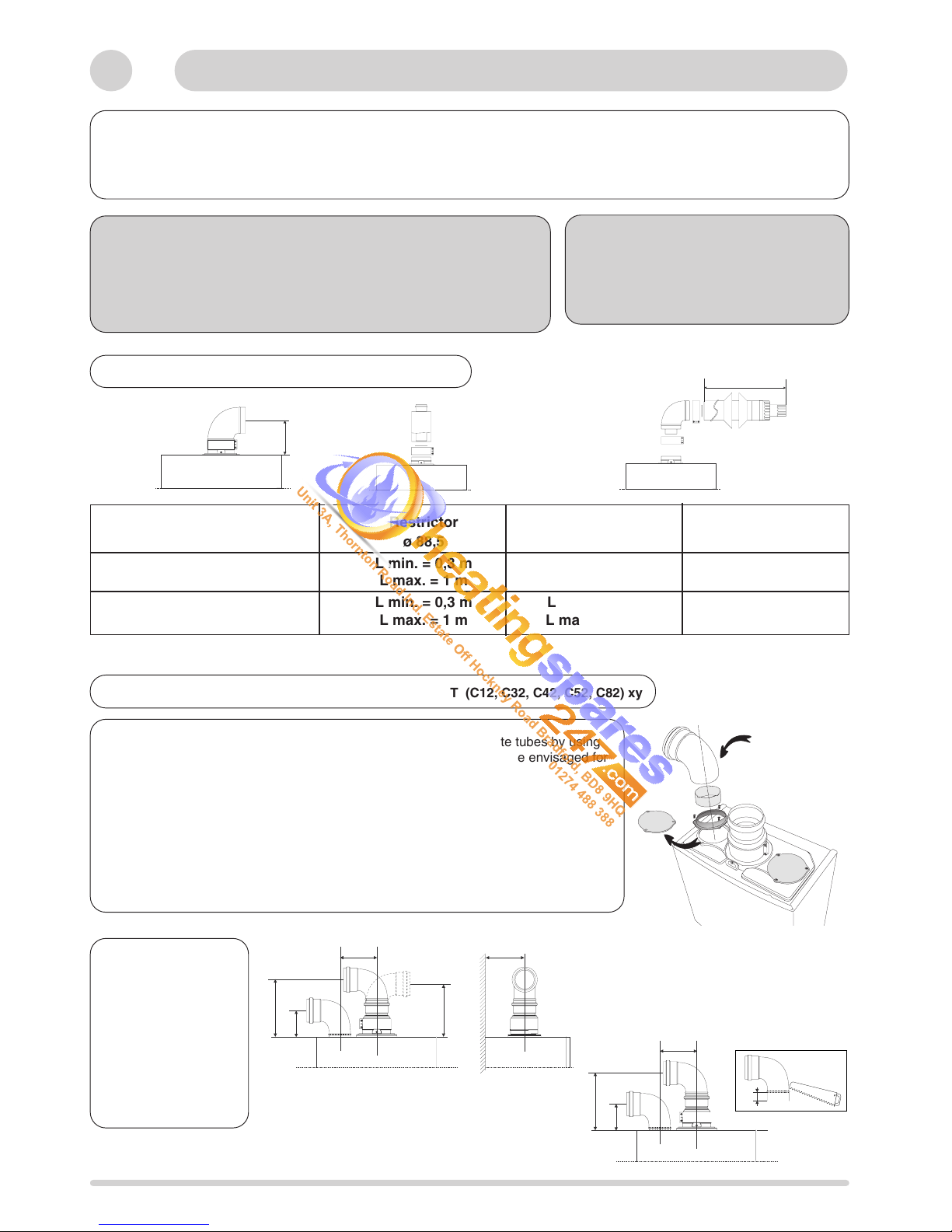
5.1 TYPE OF COAXIAL OUTLET (C12, C32, C42) xx
L max = 4 m
Ø 60/100 mm
136
The boiler should only be installed with a fresh air inlet and smoke outlet device supplied by the boiler manufacturer.
These kits are supplied separately to the appliance in order to respond to different installation solutions. For more information
with regard to the inlet/outlet accessories consult the accessory catalogue and the installation instructions contained in the kits.
The boiler is predisposed for the connection to a twin flow concentric gas intake and exhaust duct system
Warning
The exhaust gas ducts should not be in contact with or close to
inflammable material and should not pass through building structures or
walls made of inflammable material.
When replacing an old appliance, the gas intake and exhaust duct system
will also have to be changed.
Important
Ensure that the gas intake and exhaust
passages are not blocked.
Ensure that the exhaust gas ducts do not
have leaks
Concentric outlet Restrictor
60/100 ø 88,5 Without restrictor Max.length
24 kW
L min. = 0,3 m L min. = 1 m 4 m
L max. = 1 m L max. = 4 m /
30 kW
L min. = 0,3 m L min. = 1 m 4 m
L max. = 1 m L max. = 4 m /
There is also the possibility of using an exhaust gas duct with separate tubes by using
an adaptor on the outlet header and by inserting the tube in the air intake envisaged for
this purpose.
In order to use the air intake, you should:
1) Take the air intake cover off
2) Assemble the flange on the header supplied with the boiler
3) Assemble the membrane, if necessary, on the tube or the elbow
4) Insert the header on the tube or the elbow up until the lower stop
(you do not have to use the washer).
5) Insert the elbow/header in the boiler air intake hole and fasten it with screws
If the two elbows or in
the same lateral
direction and if you
need to reduce the
required space, the
minimum 230 mm
measurement can be
reduced by carefully
cutting the elbow below
the air inlet by 25 mm
123,5 135
230 MIN *
200
132
123,5
200
107
25
L = total length of gas intake and exhaust ducts.
5.2 TYPE OF TWIN FLOW CONCENTRIC EXHAUST DUCT (C12, C32, C42, C52, C82) xy
Unit 3A, Thornton Road Ind. Estate Off Hockney Road Bradford, BD8 9HQ
01274 488 388
Page 9

9
ø 100
60 mm
In the special case where the connection
is with separate tubes and with the boiler
installed at a minimum distance of 6 cm
from the wall, make a ø 10 cm hole, thus
enabling better assembly between the
fresh air elbow and the tube outside the
wall (see diagram).
The maximum development value L, mentioned in the table includes the exhaust gas/fresh air terminal and for the coaxial
system also takes into account an elbow. The C52 outlets should respect the following instructions:
1- Keep the same ø 80 mm for the gas intakes and exhaust gas ducts.
2- If you need to insert elbows in the gas intake and exhaust gas ducts, you should consider for each one the equivalent
length to be included in the calculation of developed length.
3- The exhaust gas duct should jut above the roof by at least 0.5 m.
4- The intake and exhaust gas ducts in C52 cannot be installed on opposite walls of the building
Diagram illustrating some coaxial and twin flow version installation
examples
For more detailed information concerning exhaust gas outlets and
fresh air inlets, consult our accessory catalogues
Warning
If the selected exhaust gas duct is planned
to be fitted with a membrane as indicated
in the corresponding tables, then the
installation of the membrane is compulsory
5.3 LAYING OF RESTRICTOR
Coaxial
Twin flow
Twin flow outlet Restrictor Restrictor Restrictor Without
24 kW ø 41 ø 46 ø 51 restrictor
C12, C32, C42 L min. > 0 m L min. > 2,5 m L min. > 12 m L max. > 19 m
80/80 L max. = 2,5 m L max. = 12 m L max. = 19 m L max. = 24 m
C52, C82 L min. > 0 m L min. > 10 m L max. > 29 m L max. > 35 m
80/80 L max. = 10 m L max. = 29 m L max. = 35 m L max. = 45 m
Air intake lenght 1 m.
L = total length of gas intake and exhaust ducts.
If the exhaust gas duct length is longer than 5,5 m, you will need a condensate sump
Twin flow outlet Restrictor Restrictor Without Without
30 kW ø 44 ø 50 restrictor restrictor
C12, C32, C42 L min. > 0 m L min. > 3 m L min. > 12 m L max. > 19 m
80/80 L max. = 3 m L max. = 12 m L max. = 30 m L max. = 24 m
C52, C82 L min. > 0 m L min. > 11,5 m L max. > 30 m L max. > 35 m
80/80 L max. = 11,5 m L max. = 30 m L max. = 60 m L max. = 45 m
Air intake lenght 1 m.
L = total length of gas intake and exhaust ducts.
If the exhaust gas duct length is longer than 7,5 m, you will need a condensate sump
Unit 3A, Thornton Road Ind. Estate Off Hockney Road Bradford, BD8 9HQ
01274 488 388
Page 10

10
- place the paper template in the selected position on the wall
- fit the hanging bracket
- bring the water pipes and the electrical connection to the locations shown on the fitting template
- unscrew the two clamp locking bolts A, which secure the front panel (fig. 7)
- remove the front panel
- offer the water heater up to its bracket and allow it to drop into position while pressing on it (fig. 8)
- fit the connectors and taps (fig. 9)
- connect the water and gas pipes with the various seals (rubber seal on the gas pipe)
The safety valve drain port 16 must be connected to a waste water pipe.
Fit an evacuation device according to the type of connection chosen, referring to the installation handbook supplied with the kit
Cleaning the appliance
Once the water has been connected, it is essential to clean the appliance with an appropriate product (dispersing agent) to
remove filings, solder, and various factory oils and greases.
The use of any solvent or aromatic agent (petrol, oil etc.) is forbidden.
It is advisable to treat the heating appliance completely in order to maintain a pH value of between 9 and 9.5.
6 Installing the boiler
Fig. 8
1
2
Fig. 7
Fig. 9
37
A
A
Unit 3A, Thornton Road Ind. Estate Off Hockney Road Bradford, BD8 9HQ
01274 488 388
Page 11

11
7 Electrical connections
Location of connections:
- the 230 V supply lead and room thermostat
inputs must be fitted on the wall at the height
specified on the fitting template
• the water heater is supplied with 230 V by a
twin and earth lead supplied with the appliance
• room thermostat : - allow at least 50 cm of
spare room thermostat lead for the wall input
Access to the water heater room thermostat
connection:
- the room thermostat is connected behind the
water heater control unit
Recommendation:
- to comply with regulations, a device that discon-
nects all poles with a contact opening gap of at
least 3 mm must be fitted when permanently installing the water heater
- the water heater must be connected to a fixed
boiler with the lead supplied
Fig. 10
B
C
S
T
D
J12
J1
J12
E
J1
230 V and earth connection via the lead provided at J1.
Important : If the supply cord is damaged, it must be replaced by the manufacturer or is service agent or similarly
person in order to avoid a hazard.
Room thermostat connection
Before it leaves the factory, the water heater is set to operate without a room thermostat: a shunt S is placed on connector D.
The room thermostat connection is made on this connector
- lower the electronic control unit by releasing the side locking pins P, to gain access to the reverse side
- remove screws B and remove cover C (fig. 10)
The room thermostat connection can then be accessed.
- remove connector D
- connect the thermostat in place of shunt S
- reconnect connector D
Connector J12 represented (fig. 11), is provided for connecting an optional programmer (see the relevant notice if necessary).
Fig. 11
Cable 230 V 2P + T
P
P
Unit 3A, Thornton Road Ind. Estate Off Hockney Road Bradford, BD8 9HQ
01274 488 388
Page 12

12
PRESSURISING (fig. 12)
Hot water circuit:
- open the cold water tap 34
- drain the appliance by opening the various hot water taps
Central Heating :
- Open flow and return valves on the boiler 31 and 35
- Open the automatic air vent
- Open filling taps 36 and 37, and vent radiators.
- Set system pressure, close filling taps 36, 37 and remove
filling loop 38.
- Check for leaks.
- Manually check pump is free to turn
Gas circuit
- open the gas tap 33
- flush the gas circuit
- check the sealing on the whole gas circuit
8 Operating
Fig. 12
31
33
34
35
16
SETTINGS
The water heater is supplied with all the setting buttons OFF (fig. 13) and the potentiometers turned fully anti-clockwise. It is
possible to adjust these settings if required.
In this case, it is necessary to open the electronic control unit.
Switch the water heater power on, remove the casing and open the control unit by pressing the two push buttons P (fig.
10). The setting buttons are on the circuit board behind the blanking cover E.(fig. 11)
- A1 allows the Heating Anti-cycle Timing to be set to 30 seconds or 3 minutes
HAT: period during which restarting the burner is prohibited during a heating regulation phase
- A2 allows the heating pump to be run at high or low speed
- A3 to fix the heating temperature setting to 40 °C whatever the heating temperature adjustment button position 22 (fig. 3)
- A4 enables operation either in modulating heating mode, or on/off mode
- B1 reserved
- B2 reserved
- B3 allows the hot water flowmeter timing to be adjusted to 0 or 1.5 seconds
- B4 enables operation in conjunction with a CELECTIC, in this case, switch off the flow limiter.
setting ON: the hot water setting is fixed at 65°C whatever the position of the domestic hot water temperature setting
button 21.(fig. 3)
Note: after a power cut-out or board reset, the HAT is cancelled for 3 minutes.
- P1: potentiometer to limit heating output within the setting limit made on P2 (see table on page 13)
- P2: potentiometer enabling ignition output factory set (12,7 kW - 24 FF, 16 kW - 30 FF)
- P3: reserved
Once adjustments have been made, replace blanking cover E, close the control unit cover and refit the casing.
36
37
38
Unit 3A, Thornton Road Ind. Estate Off Hockney Road Bradford, BD8 9HQ
01274 488 388
Page 13

13
P1
P2
ON OFF
A1
A2
A3
A4
B1
B2
B3
B4
P3
Pompe Grande VitessePompe Petite Vitesse
Anticycle 3 min
Fonctionnement Modulant
Tempo Débistat Sanitaire 1,5 sec Tempo Débistat Sanitaire 0 sec
Célectic
OFF
ON
Anticycle 30 s
Fonctionnement TOR
Consigne chauffage à 40 °C
Consigne chauffage variable de 35 à 85 °C
Factory setting
Fig. 13
MX2 24 FF
Gas : G20 PROPANE BUTANE
P. utile Inlet Inlet Inlet
(kW) Pressure Pressure Pressure
(mm CE) (mm CE) (mm CE)
10 18 67 47
12,7 33 111 81
16 53 172 129
20 82 258 195
24 114 352 268
Burner gas output setting
The values shown in the tables below are given for information purposes for a nominal gas distribution pressure, to allow any
adjustments to the water heater heating output according to the requirements of the appliance.
They cannot be used to calculate the precise regulated output of the water heater.
8 Operating (continued)
Célectic
Domestic flowmeter time 1.5 sec Domestic flowmeter time 0 sec.
AON operation Modulating operation
Heating setting 40 °C Variable heating setting between 35 to 85 °C
Low-speed pump High-speed pump
Anti-cycle 30 secs Anti-cycle 3 min
MX2 30 FF
Gas : G20 PROPANE BUTANE
P. utile Inlet Inlet Inlet
(kW) Pressure Pressure Pressure
(mm CE) (mm CE) (mm CE)
12 15 58 41
16 35 107 78
20 59 167 124
25 93 256 190
30 130 359 265
Unit 3A, Thornton Road Ind. Estate Off Hockney Road Bradford, BD8 9HQ
01274 488 388
Page 14

14
Fig. 15
Fitting the casing
Remove the protective film on the casing:
- offer the casing up (fig. 14)
- engage hooks N on the casing in notches R on the side panels M operation 1
- fit the top of the panel in place
- close the panel mounting clamps (fig. 15)
- screw in the two clamp locking bolts A
Note: it is essential to refit both locking bolts A
9 Fitting the casing
1
M
A
N
V
Fig. 14
R
Unit 3A, Thornton Road Ind. Estate Off Hockney Road Bradford, BD8 9HQ
01274 488 388
Page 15

15
When adapting to a gas different from the one for which the boiler is equipped, you should replace the parts delivered with the
transformation kit, as well the gas valve adjustments following the operational mode described below
Adjusting the nominal output
• take off the adjusting screws protective
cap (fig. 16).
• take off screw 2 and insert a tube
connected to a pressure tap gauge (fig. 16).
• start the boiler at maximum output (hot
water tap on).
• put pressure on nut 3 by using an 8
wrench (fig. 17) and adjust the pressure to
the value envisaged in the table
“nominal output table.”
Adjusting the minimum output
• disconnect a valve power supply cable (fig.
18)
• put pressure on screw 4 by using a 5
wrench, while holding net 3 (fig. 18) and
adjust the pressure to the value envisaged
in the table
“minimum output table.”
• adjustment finished, put screw 2 back
again and test the tightness.
• put the adjustment screws protective cab
back on.
Adjusting the minimum output
(see settings on page 12).
2
Fig. 16
3
Fig. 17
4
Fig. 18
mm CE G 20 G 30 G 31
24 kW FF 114 268 352
30 kW FF 130 265 359
Output nominal
Output mini
mm CE G 20 G 30 G 31
24 kW FF 18 47 67
30 kW FF 15 41 58
10
Gas conversion
Unit 3A, Thornton Road Ind. Estate Off Hockney Road Bradford, BD8 9HQ
01274 488 388
Page 16

16
11
Incorrect function
CODE FAULT INFORMATION
30 40 50 60 70 80
Overheating safety feature.
No flame detection.
Antifrost mode on (pump in operation).
Antifrost mode on (burner and pump in operation).
lack of water circulation.
Primary water circulation defect
Central heating inlet thermistor faulty (open circuit).
Central heating inlet thermistor faulty (short circuit).
Central heating oulet thermistor faulty (open circuit).
Central heating oulet thermistor faulty (short circuit).
Firing problem
Wiring problem (or fuse 1,25 A)
Fan on but does not activate air pressure switch.
Fan off but air pressure switch fails to return to off position.
Communication defect with the display PCB.
Communication defect with the main PCB.
If a fault occurs in the appliance, one or more LEDs (22) flash according to the fault type listed in the table below.
= LED off
= LED blinking
Unit 3A, Thornton Road Ind. Estate Off Hockney Road Bradford, BD8 9HQ
01274 488 388
Page 17

17
12
Particular characteristics
Flow rate controller assembly direction
By-pass valve assembly direction
Unit 3A, Thornton Road Ind. Estate Off Hockney Road Bradford, BD8 9HQ
01274 488 388
Page 18

18
USER’S INSTRUCTIONS
Control panel
(fig. 16)
19. - Pressure gauge
20. - On/off push button and power on indicator light
21.- Sanitary temperature setting and sanitary start button
22.- Heating temperature setting and heating start button
23.- Heating temperature indicator and operating faults
indicator
24.- Orange indicator - Burner ON
25.- Reset push button and red indicator locking light
Connecting bracket Taps shown in Open position
(fig. 17)
31 : Central heating flow isolating valve
32 : Domestic Hot Water outlet
33 : Gas service tap
34 : Water service tap
35 : Central heating return isolating valve
16 : Central heating pressure relief valve
13
Control panel
Fig.16
Fig. 17
31
32 33
34
35
16
20
21
23
25
22
24
19
c
Unit 3A, Thornton Road Ind. Estate Off Hockney Road Bradford, BD8 9HQ
01274 488 388
Page 19

19
14
Operation
Note:
In some circumstances, it is possible that the pipes (and possibly a radiator) heat up slightly after hot water is drawn. To
prevent this, simply close heating inlet tap 31 (fig. 17).
Remember to re-open it at the start of the heating season, when you switch the heating back on by pressing button 22 (fig. 16)
Starting up (fig. 17)
1. check that the appliance's general gas shut-off tap is open and that the water heater is supplied with power.
2. check that there is sufficient pressure in the heating circuit: the pressure gauge needles should be at a minimum of 1,2 bar
with 1,7 bar at maximum cold
3. open the gas inlet tap 33 (fig. 17)
Your water heater is now ready to operate.
Important
When the appliance is operated after a prolonged period of inactivity, the presence of air in the gas flues may hinder the first
attempts at igniting the gas
See section 18 “Operating faults”
To obtain hot water and heating :
To obtain hot water and heating:
Press On/Off button 20; it lights up green when power is supplied
- turn button 21 to authorise water heating ignition if water is being drawn.This button allows you to adjust the hot water
temperature. While hot water is being drawn, LEDs 23 light up two by two.
- turn button 22 to authorise heating ignition. This button enables you to adjust the water temperature in the heating
circuit according to seasonal requirements. Indicator light 23 displays this temperature
• Turn button 22 :
- to Max in cold weather,
- to Min in mild weather,
Furthermore, if your home is fitted with a room thermostat, set it to the desired indoor temperature.
- orange indicator light 24 lights up each time the burner operates
Stopping the heating
- Turn button 22 to «off » position. The water heater then produces only hot water.
Stand by mode
- Turn buttons 21 and 22 to «off »position, button 20 (fig. 16) remains lit. The function remains active unless the boiler freezes.
Turn off the water heater completely
- press push button 20 , the indicator light turns off
- turn off the electricity supply to the water heater.
- turn off the gas by turning inlet tap 33 (fig. 17)
Unit 3A, Thornton Road Ind. Estate Off Hockney Road Bradford, BD8 9HQ
01274 488 388
Page 20

20
This water heater is equipped with a flue gas extraction flow detection system which authorises operation of the burner.
If the flow is insufficient for a prolonged period of time, the water heater shuts down for safety reasons, and indicators (23) 40,
60 and 80 flash.
Important: this flue gas checking device must not be removed, or have untimely work carried out on it. If it needs to be
replaced, only original parts may be used.
16
Flue gas safety
18
Practical information
The manufacturer`s guarantee is for 12 months from the date of purchase. The guarantee is voidable if the appliance is not
installed in accordance with the recommendations made herein or in a manner not approved by the manufacturer. To assist us
in providing you with an efficient after sales service, please return the guarantee registration card enclosed with the boiler
without delay.
17
Guarantee
As with your car, your boiler will work more reliably and efficiently if regularly serviced. We recommend an annual service
check. The service history of the appliance will be marked on the logbook.
15
Maintenance
Pump anti-sticking device
When the boiler is switched on (indicator light 20 lit), the circulation pump operates for 1 minute after the water heater has
been out of operation for more than 23 hours, whatever the operation of the water heater, to prevent the pump jamming.
Precautions to take in freezing conditions
We recommend that you contact your gas fitter or After-Sales service, who will advise you of the measures to take according
to your circumstances.
Hot water circuit
The hot water circuit is drained after closing the appliance's water counter and cold water tap:
- open a hot water tap
- unscrew the cold water connection union nut
Heating circuit
Take one of the following steps:
- 1) drain the circuit of the heating appliance
- 2) protect the heating appliance with an anti-freeze product. Periodically checking the level of protection provided by this
anti-freeze is an additional guarantee requirement.
- 3) allow your appliance to run at low load by setting the room thermostat to the "anti-freeze" position (between 5 and
10°C).
- 4) leave the power to the water heater on. It is fitted with an anti-freeze device which activates the circulation pump, then
the burner.
Unit 3A, Thornton Road Ind. Estate Off Hockney Road Bradford, BD8 9HQ
01274 488 388
Page 21

21
19
Technical data
This appliance is suitable for Natural gas or LPG. A gas conversion must be made by a competent person.
Model MX2 24 FF MX2 30 FF
Appliance Category ............................................................. II 2H3+ II 2H+3+
Heat output C/H ......................................................Pn 10 to 24 kW 12 to 30 kW
Heat output DHW ...........................................Pn max 24 kW 30 kW
DHW flow rates (∆T: 30 K) ...............................................D 11,4 I/min. 14,3 I/min.
Minimum DHW operating flow rate...................................... 2 l/mn 2 l/mn
Minimum DHW working pressures .................Pw min 0,1bar 0,1bar
Maximum DHW working pressures ...............Pw max 10 bar 10 bar
C/H circuit pressure max operating ...............Pw max 3 bar 3 bar
Supply ................................................................................. 230 volts mono - 50 Hz
Consumption ....................................................................... 150 W
Protection ............................................................................ IP X4D
Natural gas G20
Gas rate max....................................................................... 2,75 m
3
/h 3,44 m3/h
Gas rate mini ....................................................................... 1,27 m
3
/h 1,50 m3/h
Nominal inlet pressure......................................................... 20 mbar 20 mbar
Burner injector dialeter in 1/100 of mm ............................... 135 130
Butane LPG G30
Gas rate max....................................................................... 2,05 kg/h 2,56 kg/h
Gas rate mini ....................................................................... 0,95 kg/h 1,12 kg/h
Nominal inlet pressure......................................................... 28 mbar 28 mbar
Burner injector dialeter in 1/100 of mm ............................... 80 80
Propane LPG G31
Gas rate max....................................................................... 2,02 kg/h 2,52 kg/h
Gas rate mini ....................................................................... 0,93 kg/h 1,10 kg/h
Nominal inlet pressure......................................................... 37 mbar 37 mbar
Burner injector dialeter in 1/100 of mm ............................... 80 80
Unit 3A, Thornton Road Ind. Estate Off Hockney Road Bradford, BD8 9HQ
01274 488 388
Page 22

22
3
6
9
12
Fig. 18
20
Instruction for setting the built in clock (if fittied)
1. General layout
The mechanical clock covers a 24 hour period. Each tappet
represents 15 minutes A (fig. 19). An override switch is
located on the clock B (fig 19).
2. To set the time
To set the time of day, grasp the outer edge of the dial and
turn slowly clockwise until the correct time is lined up with
the arrow C (fig. 19).
3. To Set the "On" and "Off" times
The clock uses a 24hours system. e.g. 8 =8.00 am and
18 = 6.00 pm "ON" periods are set by sliding all tappets
between the "ON" time and the "OFF" time to the outer edge
of the dial.The tappets remaining at the centre of the dial are
the "OFF" periods.
4. To select function mode
Put the selector switch B to symbol to control the boiler
by the clock. Put the switch B to «I» to select permanent
operation or to «0» to turn heating off permanently.
Fig. 19
1
1
2
2
3
3
4
4
5
5
6
6
7
7
8
8
9
9
10
10
11
11
12
12
13
13
14
14
15
15
16
16
17
17
18
18
19
19
20
20
21
21
22
22
23
23
24
24
9
9
6
6
12
12
I
A
C
B
Unit 3A, Thornton Road Ind. Estate Off Hockney Road Bradford, BD8 9HQ
01274 488 388
Page 23

23
21
Incorrect function
If these solutions do not cure the fault, call a qualified professional
Fault
The boiler doesn’t start
Red indicator alight
Noises in CH system
Radiators rise in temperature During
summer season
Cause
No gas, no water or no electricity
Air in the gas pipe
Room thermostat switched off
Air presence in CH system or.
Insufficient pressure
Gravity effect in the CH system
Solution
Control gas, water and electrical
supply, fuses…
Follow procedure in chapter 7
Set up the room thermostat
Wait for a few minutes
Press on reset button 25 (fig.16) the red
led turn off and the boiler attempts to relight.
If red indicator alight too frequently,
please call your localfaîtes service
centre.
Purge of air the system and rise up the
system pressure (chapter 7)
Close the heating flow isolating valve.
Don’t forget to open itagain when you
will start heating.
Unit 3A, Thornton Road Ind. Estate Off Hockney Road Bradford, BD8 9HQ
01274 488 388
Page 24

1313374a - 10/2003
Chaffoteaux & Maury are continuously improving their products and therefore reserve the right to change specifications without
prior notice and accepts no liability for any errors or omission in the information contained in this document.
Manufacturer: Chaffoteaux & Maury - France
Commercial subsidiary: MTS (GB) Limited
MTS Building
Hughenden Avenue
High Wycombe
Bucks HP13 5FT
Telephone: (01494) 755600
Fax: (01494) 459775
internet: www.chaffoteaux.co.uk
E-mail: info@mtsgb.ltd.uk
Technical Support Help Line: (01952) 222288
Unit 3A, Thornton Road Ind. Estate Off Hockney Road Bradford, BD8 9HQ
01274 488 388
 Loading...