

Page 1
Supplied By www.heating spares.co Tel. 0161 620 6677
This appliance, intended for intermittent use, is designed to supply hot water to one draw off point such as the kitchen sink or a
wash basin.
Appliance identification :
Celt Star CT with mixing taps -
A.M.I
Celt Star C without mixing taps - S.M.I
Contents : Page
1. Characteristics ...................................................................2
2. Installation Requirements ..................................................3
3. Heater installation ..............................................................4
4. Commissioning...................................................................5
5. Fitting the case...................................................................6
6. Controls and use................................................................6
7. Frost precautions ...............................................................7
8. Servicing ............................................................................7
9. Guarantee ..........................................................................8
10. Overflow safety...................................................................8
11. Operating Defects ..............................................................8
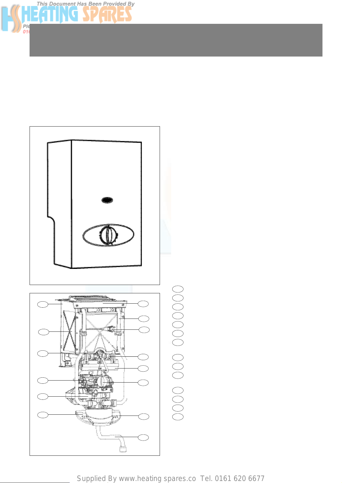
Description:
The water heater is packaged in one box.
Inside its one-piece case, the water heater comprises:
- One-piece chassis made of protected steel sheet
- Deflector
- Heat exchanger made of protected copper
- Combustion chamber
- Multi-gas burner made of stainless steel
- Removable injector-holder manifold
- Pilot with fail-safe by thermocouple and atmosphere
sensing device.
- Gas valve
- Gas ignition and flow control knob
- Water valve with built-in overheat limiter and scale
reducer
- Fouling prevention thermal safety device
- Hot water tap ("A.M.I" models)
- Cold water tap ("A.M.I." models).
- Spout
14
13
12
11
10
9
8
7
6
5
4
3
2
1
CELT STAR C
GAS-FIRED WATER HEATER
Category: I 2E+
Installation and use instructions
These installation and User instructions are intended for appliances installed in Great Britain.
Fig. 1 Model S.M.I.
Fig. 2 Model A.M.I.
11
12
10
8
7
4
1
9
6
5
3
2
c
13
14
Page 2
Supplied By www.heating spares.co Tel. 0161 620 6677
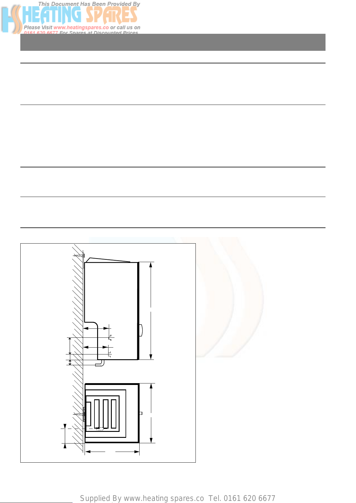
1. Technical characteristics and dimensions
Cold water
Gas
220
246
Fig. 3
2
TECHNICAL CHARACTERISTICS
Rated heat input .................................................................................................................................... =10.0 kW (34120 Btu/h)
Rated power output ................................................................................................................................. =8.5 kW (29002 Btu/h)
Flow rate of water heated from 15 to 40 °C ........................................................................................... = 5 I/min
Flow rate of water heated from 15 to 65 °C ........................................................................................... = 2.5 I/min
Minimum water pressure to operate the “normal pressure” valve: ......................................................... = 0.2 bar (3 lb/in
2
)
Minimum water pressure to operate the “low pressure” valve: ............................................................... = 0.1 bar (1.5 lb/in
2
)
Maximum “normal pressure” water pressure (with governor) :................................................................ = 10 bar (145 lb/in
2
)
Maximum “low pressure” water pressure (without governor) : ................................................................ = 2.5 bar (36,25 lb/in
2
)
Fresh air flow rate :.................................................................................................................................. = 21.5 m
3
/h
Gas flow rates (15°C - 1013 mbar) Inlet Pressure Gas rate
G 20 (Natural gas)..............................................................20 mbar (8in wg).......................................... = 1.06 m3/h
Injector identification ............................................................................................................................... Burner Pilot
G 20 gas (with disc marked DIA 2.70) ...................................................................................................... INJ 123 26-40
• 1 bar = 1,02 kg/cm2(the pressure must be measured at the appliance inlet, while the appliance is working).
409
102
101
Hot water
20
60
20
103
Hot water
Page 3
Supplied By www.heating spares.co Tel. 0161 620 6677
2. Installation Requirements
3
2.1 Related Documents
The installation of the heater must be in accordance with the
relevant requirements of the Gas Safety (Installation and Use)
Regulations, Building Regulations and the Byelaws of the local
Water Undertaking. It should be in accordance also with any
relevant requirements of British Gas and local authority, and
the relevant recommendations of the following current British
Standard Codes of Practice :
BS 6891 : Specification for installation of low pressure
gas pipework up to 28 mm (Rl) in domestic
premises (2nd family gases).
BS 5546 : Installation of gas hot water supplies for
domestic purposes (second family gases).
BS 5440 : Flues and air supply for gas appliances of
rated input not exceeding 60 kW (1st, 2nd
and 3rd family gases).
Part 1 Flues
Part 2 Air Supply
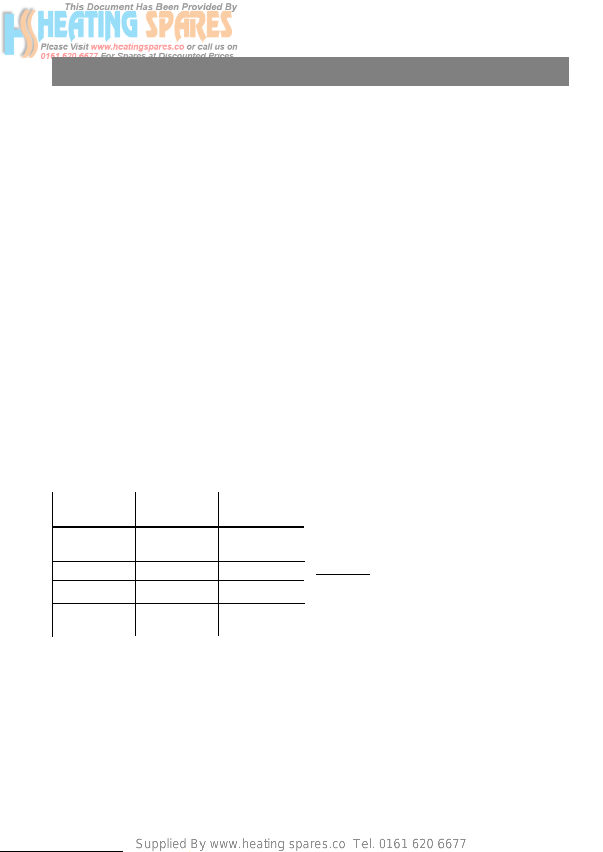
2.2 Air Supply
IMPORTANT : This heater should be used in a well ventilated
room. An air vent direct to outside is required where the room
volume is less that 20 m
3
size in accordance with the following
table. In addition an openable window is required.
This heater must not be installed in a space less than 5 m3in
total volume.
This water heater is fitted with an atmospheric sensing device
which will turn off the gas supply to the pilot and burner, when
the oxygen in the atmosphere in the locality of the heater is
diminished and will not support safe combustion. It also pro-
tects the user if the heat exchanger fins become blocked.
It is therefore important that the heater is not located over a
cooker or in a position where the air supply is restricted or
contaminated.
The location must also permit space for servicing and air circulation around the appliance.
2.3 Gas Supply
An adequate sized gas meter must be connected to the service pipe. Where necessary British Gas will arrange for the existing meter to be checked or for a suitable meter to be installed.
On no account must any work be carried out on the gas meter
other than by British Gas or their specifically authorised
contractor.
Installation pipes should be fitted in accordance with BS 6891:
Pipework from the meter must be of adequate size. Pipes of a
smaller size than the gas connection should be not used,
The complete installation must be tested for gas soundness
and purged in accordance with BS 6891.
In addition to any other gas appliance installed in the premises, the meter should be capable of passing : 40 cu, ft/h of
natural gas.
2.4 Description of Operation of Special Components
2.4.1 Atmospheric Sensing Device
The thermoelectric circuit is fitted with a thermal switch located
on the front of the combustion chamber of the heater.When the
oxygen in the atmosphere in the locality of the heater becomes
diminished and is unable to support safe combustion, the products of combustion pass through an orifice in the front panel
and the increase in temperature is detected by the thermal
switch. When the switch is activated it interrupts the thermoelectric circuit and the pilot and main burner are extinguished.
2.4.2 Scale Reducer
The scale reducer is a diaphragm vessel forming part of the
water section. At the termination of a demand cycle the
contens of the heat exchanger are displaced into the vessel
and replaced with cold water.
2.5 Flue
These appliances are flueless. Protection is provided in the
form of the atmospheric sensing device (see Section 2.5.1).
They must not be operated continuously for more than five
minutes.
CONTR
OL OF SUBSTANCES HARMFUL
T
O HEALTH
IMPOR
TANT
To comply with the Control of Substances Harmful to Health
Regulations 1988 we are required to provide information on the
following substance that is contained in this appliance.
Description
Combustion Chamber
Material
Alumino Silicone Fibre
Precautions
During servicing, keep the dust generation to a minimum and
avoid inhaling any dust and contact with the skin and eyes.
Normal handling and use will not present any discomfort,
although some people with a history of skin complaints may be
susceptible to irritation.
When disposing of the lining ensure that it is securely wrapped
and wash hands after contact.
Room Permanent Openable
Volume Air vent Window
0 - 5 m
3
Installation
not permitted
5 m
3
- 10 m
3
100 cm
2
YES
11 m
3
- 20 m
3
50 cm
2
YES
over 20 m
3
NIL YES
Page 4

Supplied By www.heating spares.co Tel. 0161 620 6677
3. Water heater installation
Mounting the appliance
- fix the wood screw of the support bracket 395 mm above the centreline of the water outlet
- remove the gas control knob (fig. 2) pulling it towards you
- remove the four screws "V" (fig. 10) securing the case
- remove the case
- position the appliance, engaging the slot cut in the chassis on the support bracket (fig. 4).
9
395
EF
Water axes
Fig. 4
4
Connections
The appliance is delivered complete, ready to install. The
accessories pouch contains the following items :
Natural gas connection (fig. 5) :
- one valve Ø 3/4" F / Ø 1/2" M with
1/2" gasket
- one brazed angle socket Ø 14 x 0,75 with nut
and gasket.
Cold water connection (fig. 6) :
- one M16 union
,
one 1/2 nut
,
two gaskets
, one valve Ø 1/2" M / Ø 1/2" M, one water
filter (with built-in mixer AMI only).
Hot water connection (fig. 5) :
- one blanking disc with 3/8" nut and gasket or one
tube Ø 12 x 1 with 3/8" nut and gasket.
23
20
1918
1716
15
14
Fig. 5
14
23
22
15
Fig. 6
16
18
17
19
20
18
Important : Clean the inside of the water and gas pipes of the installation thoroughly before connecting the appliance.
Page 5

Supplied By www.heating spares.co Tel. 0161 620 6677
- make sure that the cold water inlet valve item (fig. 6) and the gas valve
item (fig.5) are open
- make sure that there is no leakage along the entire gas line
- fit the gas knob temporarily
- turn on the water heater
- follow the instructions in section 6, Controls and use.
14
19
4. Commissioning
5
stop
detail
driving
cam
Maximum gas power adjustment
(if necessary) :
The appliance is adjusted in the factory for
a rated gas supply pressure (refer to the
Technical characteristics).
In the case of a higher supply pressure, the
maximum gas power can be adjusted by
proceeding as follows :
detach the stop from the fascia (fig. 7a)
place it on the gas control cam (fig. 7b).
Fig. 7a
Fig. 7b
Water pressure adjustment
(if necessary) :
The appliance is configured for normal
water pressure
If your water supply pressure is low (< 2,5
bar), your appliance should be converted by
proceeding as follows :
- remove the case (refer to section 5)
- remove the pin
A (fig. 8)
- withdraw the water control B (fig.8)
- remove the water filter
C (fig. 9)
- remove the governor D (fig. 9)
- replace the water filter and reassemble
the components in reverse order.
B
A
Fig. 8
Fig. 9
C
D
Page 6

Supplied By www.heating spares.co Tel. 0161 620 6677
5. Fitting the case
- remove the protective film from the case
- fit the two pinch nuts, delivered in the accessories pouch, on the deflector
- position the case top-first (fig. 10)
- fit the four screws “v”
- fit the fascia attachment screw (fig. 10a) (supplied in the accessories pouch)
- fit the gas control knob.
6
Fig. 10
6. Controls and use
Fig. 11
Control panel (fig. 11):
Gas control knob symbols :
: Off : Reduced power
: Pilot ignition
•
•
:
Intermediate
piezo triggering
•
•
•
:
powers
: Pilot position
: Maximum power
Note : The shape and colour of the control panel may differ according to the model.
Controls
Fig. 10a
Fig. 12
Built-in mixer tap (fig. 12) :
The "A.M.I." models incorporate a mixer tap with "quick-connect" ceramic heads for
use over a draw-off point.
This mixer tap comprises :
: a cold water lever
: a hot water lever
: spout
26
25
24
25
24
26
Page 7

Supplied By www.heating spares.co Tel. 0161 620 6677
7. Frost precautions
- We advise you to contact your installer or your after-sales service to obtain details of the most suitable measures for your
installation.
Take the following steps :
- turn the heater off
- close the cold water inlet valve item (fig. 6, page 4)
- open a hot water tap
- unscrew the drain plug item (fig. 5, page 4).
22
19
To light the pilot
Turn the gas control knob in the direction of the arrow.
The click at the " " (fig. 13) generates the pilot ignition spark.
Note :The first time the pilot is lit, it may be necessary to
wait a few moments for the air to be pushed out of the pilot
circuit before the pilot lights. In this case, hold the knob for
a few moments at the " " mark, then repeat the operation
until the pilot lights.
- When the pilot lights, hold the knob at the " " mark for a few
seconds to set the thermocouple safety device, then turn the
knob further in the direction of the arrow until it is between
" " and " " (fig. 14).
Power adjustment
- This water heater, with automatic power variation, is fitted
with a system enabling the user to limit its maximum power.
To do this, turn the knob until it is between the
" " and " ".
- This appliance operates in such a way that it can be used
over a wide range of flow rates without adjusting the power.
The hot water temperature is determined by the draw-off
flow rate.
To turn off the heater
Turn the control knob back to the " " mark.
7
Fig. 13
Fig. 14
Use
6. Controls and use (continued)
8. Servicing
Annual servicing of your water heater is necessery.
Have the heater inspected by a qualified professional once a year.
Annual service contracts covering all the servicing operations on your water heater can be offered to you by service providers.
Contact your installer or our Customer Services Department.
Descaling: Only the heat exchanger should be descaled. The descaling agent must never be allowed to flow through the water
valve.
In order to ensure the safety of the consumer, we remind you that thorough rinsing is necessary after descaling before the heater is put back into service.
The manufacturers warranty covers manufacturing defects but not malfunction caused because of the need for service.
The case surface can be cleaned with soapy water or a non-abrasive cleaning agent, using a soft cloth.
Page 8

Supplied By www.heating spares.co Tel. 0161 620 6677
9. Guarantee
10. Safety
Your water heater is guaranteed for a period of one year.
The terms of the guarantee are explained in the guarantee certificate.
IMPORTANT : Make sure that the detachable coupon on the certificate has been returned to CHAFFOTEAUX & MAURY.
In order to benefit from the guarantee, your water heater must have been installed, adjusted and commissioned by a qualified
professional. This gives you the assurance that your installer has complied with the installation instructions and that the regulations and safety conditions have been satisfied.
This water heater incorporates safety devices in compliance with the Gas Safety (Installation & Use) Regulations 1998.
- an atmosphere sensing device which shuts down the water heater if the premises where it is installed are inadequately
ventilated
- a preventive service safety device which shuts down the water heater in the event of abnormal fouling of the heating body.
The incorporation of these devices means that the appliance can be installed without being connected to a flue.
After shutdown the water heater is in the “safety” position. After approximately five minutes, it can be turned on again manually,
following the normal lighting procedure. If the appliance shuts down repeatedly, you must contact a qualified professional.
Warning :
- these safety devices must not be rendered inoperative
- only CHAFFOTEAUX & MAURY original parts must be used for replacement.
Incidents
You do not have any hot water
The water heater does not come on.
The pilot does not light.
The water heater turns off while water is
being drawn.
Causes
Water inlet valve closed.
No gas, pilot not lit
No water.
Gas valve closed
Air in the gas circuit.
Inadequate ventilation or extraction of
fumes.
Solutions
Open the valve
Light the pilot
Make the necessary checks
(gas inlet, water on).
Open the valve
May occur after a long shutdown
Repeat the lighting procedure (refer to
section "6").
- air the premises thoroughly
- make sure that the top and bottom
ventilation openings are not obstructed.
- put the appliance back into service by
lighting the pilot.
If these solutions are not effective, contact a qualified professional.
11. Operating defects
Réf. : 1304123- 12/2000
Chaffoteaux & Maury
Trench Lock
Trench
Telford
TF1 4SZ
Tel 01052 222727
Fax 01952 243493
c
 Loading...