

Page 1
OPERATING, MAINTENANCE
& PARTS MANUAL
MANUAL DE FUNCIONAMIENTO,
MANTENIMIENTO Y PIEZAS
MANUEL D'ENTRETIEN,
D'OPÉRATION ET DE PIÈCES
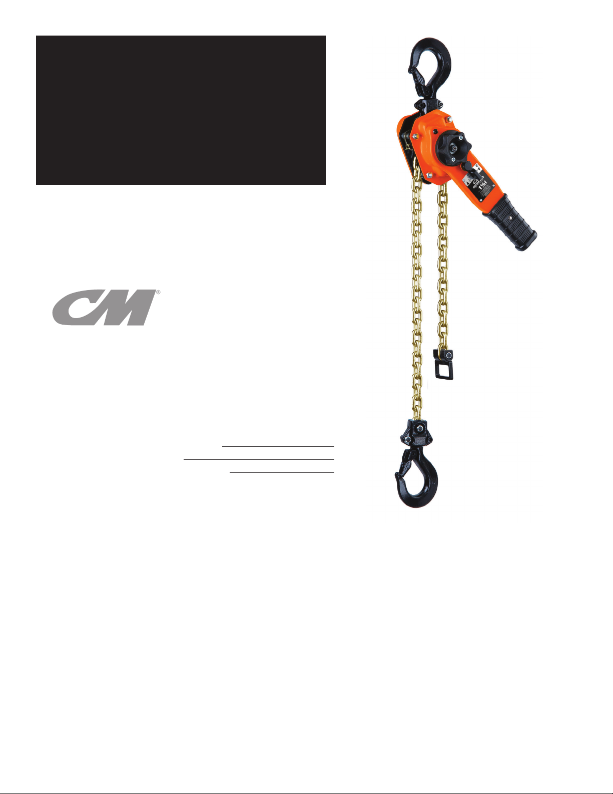
HAND OPERATED LEVER HOIST
POLIPASTO MANUAL DE PALANCA
PALAN MANUEL À LEVIER
SERIES 653-A
LEVER HOIST
Before installing hoist, fill in the information below.
Antes de instalar el polipasto, rellene los datos siguientes.
Enregistrez les informations suivantes avant de faire l'installation.
Rated Load / Carga Nominal / Charge nominale
Serial No. / N° de Serie / No. de Ser.
Purchase Date / Fecha de Compra / Date d'achat
CAPACITIES:
3/4, 1, 1½, 2, 3 and 6 TON
(750, 1000, 1500, 2000,
3000 and 6000 kg.)
Follow all instructions and warnings
for inspecting, maintaining and
operating this hoist.
The use of any hoist presents some risk
of personal injury or property damage. That
risk is greatly increased if proper instructions
and warnings are not followed. Before using
this hoist, each operator should become
thoroughly familiar with all warnings,
instructions and recommendations
in this manual. Retain this manual for
future reference and use.
Forward this manual to operator.
Failure to operate equipment as
directed in manual may cause injury.
CAPACIDADES DE CARGA:
3/4, 1,1½, 2, 3 y 6 toneladas
(750, 1000, 1500, 2000, 3000 y
6000 kg.)
Siga todas las instrucciones y
advertencias para inspeccionar,
mantener y operar este polipasto.
El uso de cualquier polipasto presenta algunos
riesgos de daños a las personas o a las
cosas. Este riesgo se ve incrementado si no
se siguen correctamente las instrucciones
y advertencias. Antes de usar el polipasto
el operario debería estar familiarizado con
rodas las advertencias, instrucciones y
recomendaciones de este manual. Guarde
este manual para futuras consultas.
Entregue este manual al operario. Si el
equipo no se maneja tal y como se
recomienda en el presente manual, es
posible que se produzcan situaciones
de peligro que pueden resultar en
daños personales.
CHARGES NOMINALES:
3/4, 1,1½, 2, 3 et 6 TONNES
(750, 1000, 1500, 2000, 3000 et
6000 kg.)
Veuillez vous conformer à toutes les
instructions et avertissements d'inspection,
d'entretien et d'opération de ce palan.
L'utilisation de tout appareil de levage
comporte des risques de blessures ou
de dégâts matériels. Ces risques sont
de beaucoup accrus si les instructions
et avertissements ne sont pas suivis.
Tous les opérateurs devraient se
familiariser complètement avec toutes
les recommandations instructions et
avertissements de ce manuel avant d'utiliser
ce palan. Conservez ce manuel pour
utilisation et référence future.
Remettre ce manuel à l'opérateur.
L'utilisation de cet équipement contrairement
aux directives de ce manuel peut causer
des blessures.
P/N: 192065084 Rev AA March 2020
Page 2
WARRANTY
ENGLISH
LIMITATION OF WARRANTIES, REMEDIES AND DAMAGES
INDEMNIFICATION AND SAFE OPERATION
Buyer shall comply with and require its employees to comply with directions
set forth in instructions and manuals furnished by Seller and shall use
and require its employees to follow such instructions and manuals and
to use reasonable care in the use and maintenance of the goods and any
replacement parts. Buyer shall not remove or permit anyone to remove any
warning or instruction signs on the goods or replacement parts. In the event
of personal injury or damage to property or business arising from the use of
the goods or replacement parts, Buyer shall within 48 hours thereafter give
Seller written notice of such injury or damage. Buyer shall cooperate with
Seller in investigating any such injury or damage and in the defense of any
claims arising therefrom.
If Buyer fails to comply with this section or if any injury or damage is
caused, in whole or in part, by Buyer’s failure to comply with applicable
federal or state laws, rules or regulations safety requirements, Buyer shall
indemnify and hold Seller harmless against any claims, loss or expense
for injury or damage arising from the use of the goods and/or replacement
parts.
CMCO Warranty (HOISTS)
A. Columbus McKinnon Corporation (“Seller”) warrants to the original
end user (“Buyer”) that, for a period of one (1) year from the date of
Seller’s delivery of the goods (collectively, the “Goods”) to the carrier,
the Goods will be free from defects in workmanship and materials. (b)
for a period of three (3) years from the date of Seller’s delivery of the
Goods to the carrier, the brake discs on the Goods will be free from
defects in workmanship and materials; and (c) for the life of the Goods,
the mechanical components including, without limitation, the sidewinder
hoist lever, of the Goods (other than the brake discs on the Goods) will
be free from defects in workmanship and materials. . In addition, Seller
warrants to Buyer that, for a period of one (1) year from the date of their
delivery by Seller to the carrier, any aftermarket or replacement parts,
accessories or components purchased by Buyer with respect to any
Goods (collectively, “Replacement Parts”) will be free from defects in
workmanship and materials.
B. IN THE EVENT OF ANY BREACH OF ANY SUCH WARRANTY, SELLER’S
SOLE OBLIGATION SHALL BE EXCLUSIVELY LIMITED TO, AT THE
OPTION OF SELLER, REPAIR OR REPLACEMENT, F.O.B. SELLER’S
POINT OF SHIPMENT, OF ANY GOODS OR REPLACEMENT PARTS
THAT SELLER DETERMINES TO HAVE BEEN DEFECTIVE OR, IF
SELLER DETERMINES THAT SUCH REPAIR OR REPLACEMENT IS NOT
FEASIBLE, TO A REFUND OF THE PURCHASE PRICE UPON RETURN
OF THE GOODS OR REPLACEMENT PARTS TO SELLER. NO CLAIM
AGAINST SELLER FOR ANY BREACH OF (i) SUCH WARRANTY WITH
RESPECT TO THE ELECTRICAL COMPONENTS OF ANY GOOD OR
REPLACEMENT PARTS SHALL BE VALID OR ENFORCEABLE UNLESS
BUYER’S WRITTEN NOTICE THEREOF IS RECEIVED BY SELLER WITHIN
ONE (1) YEAR FROM THE DATE OF SELLER’S DELIVERY TO THE
CARRIER, (ii) SUCH WARRANTY WITH RESPECT TO THE BRAKE DISCS
OF ANY GOOD SHALL BE VALID OR ENFORCEABLE UNLESS BUYER’S
WRITTEN NOTICE THEREOF IS RECEIVED BY SELLER WITHIN THREE
(3) YEARS FROM THE DATE OF SELLER’S DELIVERY TO THE CARRIER
AND (iii) SUCH WARRANTY WITH RESPECT TO THE MECHANICAL
COMPONENTS, INCLUDING, WITHOUT LIMITATION, THE SIDEWINDER
HOIST LEVER, OF ANY GOOD (OTHER THAN THE BRAKE DISCS ON
ANY GOOD) SHALL BE VALID OR ENFORCEABLE UNLESS BUYER’S
WRITTEN NOTICE THEREOF IS RECEIVED BY SELLER WITHIN ONE (1)
YEAR FROM THE DATE ANY ALLEGED CLAIM ACCRUES. EXCEPT FOR
THE WARRANTIES SET FORTH ABOVE, SELLER MAKES NO OTHER
WARRANTIES WITH RESPECT TO THE GOODS OR ANY REPLACEMENT
PARTS, WHETHER EXPRESSED OR IMPLIED, INCLUDING ANY
WARRANTIES OF MERCHANTABILITY, FITNESS FOR A PARTICULAR
PURPOSE, QUALITY AND/OR THOSE ARISING BY STATUTE OR
OTHERWISE BY LAW OR FROM ANY COURSE OF DEALING OR USE OF
TRADE, ALL OF WHICH ARE HEREBY EXPRESSLY DISCLAIMED.
C. IN NO EVENT SHALL SELLER BE LIABLE TO BUYER OR ANY THIRD
PARTY WITH RESPECT TO ANY GOOD OR REPLACEMENT PART,
WHETHER IN CONTRACT, TORT OR OTHER THEORY OF LAW, FOR
LOSS OF PROFITS OR LOSS OF USE, OR FOR ANY INCIDENTAL,
CONSEQUENTIAL, SPECIAL, DIRECT OR INDIRECT DAMAGES,
HOWSOEVER CAUSED. SELLER’S MAXIMUM LIABILITY TO BUYER
WITH RESPECT TO THE GOODS OR ANY REPLACEMENT PART
SHALL IN NO EVENT EXCEED THE PRICE PAID BY BUYER FOR THE
GOODS OR REPLACEMENT PART THAT ARE THE SUBJECT OF THE
APPLICABLE CLAIM.
D. Seller shall not be liable for any damage, injury or loss arising out of the
use of the Goods or any Replacement Part if, prior to such damage, injury
or loss, such Goods or Replacement Parts are: (1) damaged or misused
following Seller’s delivery to the carrier; (2) not maintained, inspected, or
used in compliance with applicable law and Seller’s written instructions
and recommendations; or (3) installed, repaired, altered or modied (a) with
any part or accessory other than those supplied by Seller or (b) without
compliance with such laws, instructions or recommendations.
E. This warranty is limited and provided only to the original end user. Each
Good and Replacement Part must be registered within sixty (60)
days of receipt of each product to establish eligibility. Please register
at www.cmworks.com/hoist-warranty-registration or submit registration
card via US mail.
F. Any action against Seller for breach of warranty, negligence or otherwise
in connection with the electrical components of any Good must be
commenced by Buyer within one (1) year after: (a) the date any alleged
claim accrues; or (b) the date of delivery of the Goods to Buyer,
whichever is earlier. Any action against Seller for breach of warranty,
negligence or otherwise in connection with the brake discs on any
Good must be commenced by Buyer within three (3) years after: (y) the
date any alleged claim accrues; or (z) the date of delivery of the Goods
to Buyer, whichever is earlier. Any action against Seller for breach of
warranty, negligence or otherwise in connection with the mechanical
components of any Good (other than the brake discs on any Good)
must be commenced by Buyer within one (1) year after the date any
alleged claim accrues. Any action against Seller for breach of warranty,
negligence or otherwise in connection with any Replacement Part must
be commenced by Buyer within one (1) year after: (y) the date any alleged
claim accrues; or (z) the date of delivery of the Replacement Part to
Buyer, whichever is earlier.
G. This warranty is contingent upon Buyer’s proper maintenance and care
of the Goods and/or Replacement Part, and does not extend to normal
wear and tear. Seller reserves the right, at its option, to void this warranty
in the event of Buyer’s use with the Goods and/or Replacement Parts of
parts or accessories other than those supplied by Seller.
Alterations or modications of equipment and use of non-Seller
replacement parts can lead to dangerous operation and injury.
TO AVOID INJURY:
• Do not alter or modify equipment.
• Do use only replacement parts manufactured by seller.
1
(ENGLISH)
P/N: 192065084 Rev AA March 2020
Page 3

CM HOIST PARTS AND SERVICES ARE AVAILABLE
IN THE UNITED STATES AND IN CANADA
As a CM Hoist and Trolley user you are assured of reliable repair and parts services through a network of Master Parts Depots and Service Centers
that are strategically located in the United States and Canada. These facilities have been selected on the basis of their demonstrated ability to handle
all parts and repair requirements promptly and efciently. To quickly obtain the name of the Master Parts Depot or Service Center located nearest you,
go to www.cmworks.com, phone (800) 888-0985, Fax: (716) 689-5644.
LAS PIEZAS Y REPARACIONES DE LOS POLIPASTOS DE CM ESTÁN
ASEGURADAS EN ESTADOS UNIDOS Y CANADÁ
Como usuario de un polipasto y carro de CM le aseguramos cualquier reparación o la disponibilidad de cualquier pieza de repuesto a través de una
red de almacenes de piezas de repuesto y centros de servicio situados estratégicamente en Estados Unidos y Canadá. Estas instalaciones se han
seleccionado en base a su capacidad demostrada en la reparación de equipos y suminstro de piezas de repuesto de forma rápida y ecaz. Para obtener
la dirección del almacén de piezas de repuesto o del centro de servicio más cercano, vaya a www.cmworks.com, teléfono (800) 888-0985,
Fax: (716) 689-5644 (sólo en Estados Unidos y Canadá).
LE SERVICE DE RÉPARATION ET DE PIÈCES POUR PALANS CM EST
DISPONIBLE AUX ÉTATS-UNIS ET AU CANADA
Soyez assurés qu'en temps d'utilisateur de palan et treuil CM, d'un service de réparation et de pièces able par l'entremise d'un réseau de Centres de
service et de Dépôts de pièces maîtresses qui sont stratégiquement situés aux États-Unis et au Canada. Ces établissements ont été sélectionnés sur une
base de leur habileté démontrée à s'occuper promptement et efcacement des besoins de réparation de pièces. Aller à www.cmworks.com,
téléphone (800) 888-0985, Fax: (716) 689-5644 pour obtenir rapidement le nom du dépôt de pièces maîtresses ou du centre de service situé le plus près.
ENGLISH
2
(ENGLISH)
P/N: 192065084 Rev AA March 2020
Page 4
ENGLISH
Improper operation of a hoist can create a potentially hazardous
situation which, if not avoided, could result in death, or serious
injury. To avoid such a potentially hazardous situation, the
operator shall:
1. NOT operate a malfunctioning or unusually performing hoist.
2. NOT operate the hoist until you have thoroughly read and
understood this manual.
3. NOT operate a hoist which has been modied without the
manufacturer’s approval or certication to be in conformity
with applicable OSHA regulations.
4. NOT lift or pull more than rated load for the hoist.
5. NOT use damaged hoist or hoist that is not working properly.
6. NOT use hoist with twisted, kinked, damaged,
or worn load chain.
7. NOT operate with any lever extension (cheater bar).
8. NOT attempt to “free chain” the hoist while a load is applied.
9. NOT use the hoist to lift, support, or transport people.
10. NOT lift loads over people and make sure all personnel
remain clear of supported load.
11. NOT attempt to lengthen the load chain or repair damaged
load chain.
12. Protect the hoists load chain from weld splatter or other
damaging contaminants.
13. NOT operate a hoist when it is restricted from forming a
straight line from hook to hook in the direction of loading.
14. NOT use load chain as a sling or wrap load chain around load.
15. NOT apply the load to the tip of the hook or to the hook latch.
16. NOT apply load unless load chain is properly seated in the
chain wheel(s) or sprocket(s).
17. NOT apply load if bearing prevents equal loading on all load
supporting chains.
18. NOT operate beyond the limits of the load chain travel.
19. NOT leave load supported by the hoist unattended unless
specic precautions have been taken.
20. NOT allow the chain or hook to be used as an electrical
or welding ground.
21. NOT allow the chain or hook to be touched by
a live welding electrode.
22. NOT remove or obscure the warnings on the hoist.
23. NOT operate a hoist which has Not been securely attached
to a suitable support.
24. NOT operate a hoist unless load slings or other approved
single attachments are properly sized and seated
in the hook saddle.
25. NOT lift loads that are Not balanced and the holding action
is Not secure, taking up slack carefully.
26. NOT operate a hoist unless all persons are and remain clear
of the supported load.
27. Report malfunctions or unusual performances of a hoist,
after it has been shut down until repaired.
28. NOT operate a hoist on which the safety placards or decals
are missing or illegible.
29. Be familiar with operating controls, procedures and warnings.
Improper operation of a hoist can create a potentially hazardous
situation which, if not avoided, could result in minor or moderate
injury. To avoid such a potentially hazardous situation, the
operator shall:
1. Maintain a rm footing or be otherwise secured when
operating the hoist.
2. Check brake function by tensioning the hoist prior to each
lift or pulling operation.
3. Use hook latches. Latches are to retain slings, chains, etc.
under slack conditions only.
4. Make sure the hook latches are closed and not supporting
any parts of the load.
5. Make sure the load is free to move and will clear
all obstructions.
6. Avoid swinging the load or hook.
7. Avoid lever “y-back” by keeping a rm grip on the lever
until operating stroke is completed and lever is at rest.
8. Inspect the hoist regularly, replace damaged or worn parts,
and keep appropriate records of maintenance.
9. Use Columbus McKinnon parts when repairing the unit.
10. Lubricate load chain as recommended in this manual.
11. NOT operate except with manual power.
12. NOT permit more than one operator to pull on lever at
the same time. More than one operator is likely to cause
hoist overload.
13. NOT allow your attention to be diverted from operating
the hoist.
14. NOT allow the hoist to be subjected to sharp contact
with other hoists, structures, or objects through misuse.
15. NOT adjust or repair the hoist unless qualied to perform
such adjustments or repairs.
The hoists are intended for general industrial use
for moving loads within their load ratings. Prior
to installation and operation, the user should
review the application for abnormal environmental
or handling conditions.
GENERAL SAFETY INFORMATION
ADVERSE ENVIRONMENTAL CONDITIONS
Do not use the hoists in areas containing ammable vapors, liquids,
gasses or any combustible dust or bers. Do not use the hoist
in highly corrosive, abrasive, wet environments or in applications
involving exposure to temperatures below -10ºF or above 130ºF.
MOVING HAZARDOUS LOADS
The hoists are not recommended for lifting materials that could
cause widespread damage if dropped. The lifting or moving of
materials that could explode or cause chemical or radioactive
contamination requires fail-safe, redundant supporting devices
that are not incorporated into these hoists.
3
(ENGLISH)
P/N: 192065084 Rev AA March 2020
Page 5
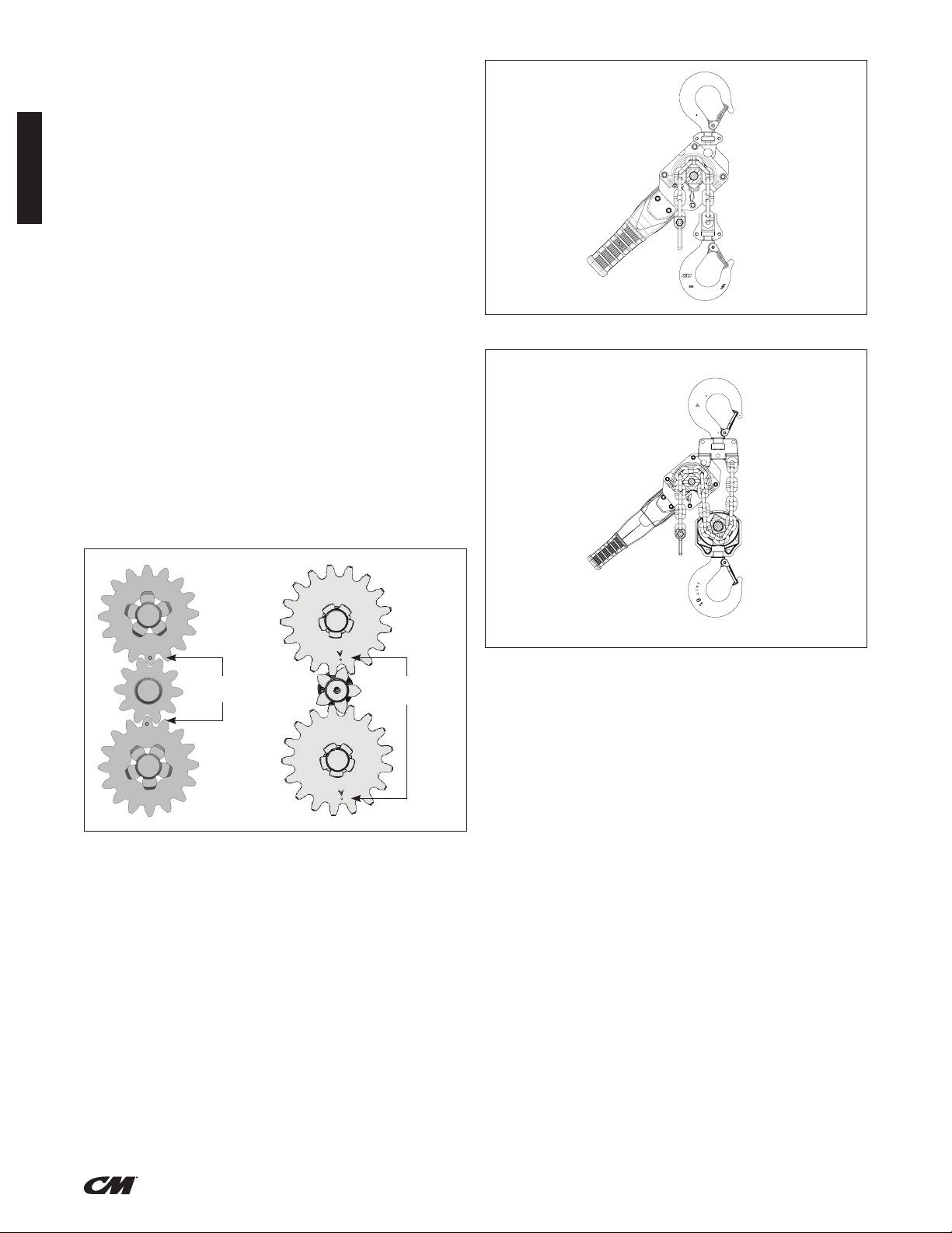
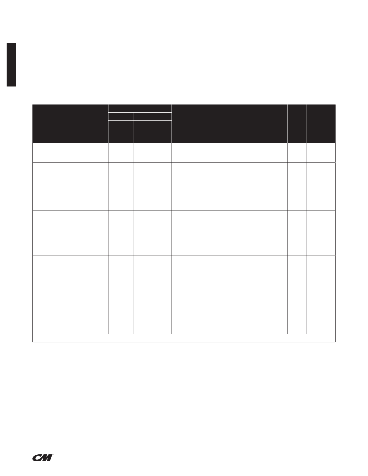
DESCRIPTION
Series 653-A Hand Operated Lever Hoists are highly versatile tools that can be used in any position to efciently pull, lift, drag or stretch.
The frame, covers and lever are made from steel stampings. The gears are heat treated steel, upper and lower hooks are forged steel
and
the chain is heat treated, welded link type.
Hoist with load ratings of 3/4, 1, 1½, 2, 3 and 6 ton are available and this manual applies to all of these units. The hoists are available
with 5, 10, 15 and 20 foot long chains.
Hooks with latches are standard on all units.
Series 653-A Hand Operated Lever Hoists are built in accordance with the specication contained herein and at the time of manufacture
complies with the applicable sections of the American Society of Mechanical Engineers (ASME) Standard B30.21: Manually Operated
Lever Hoists.
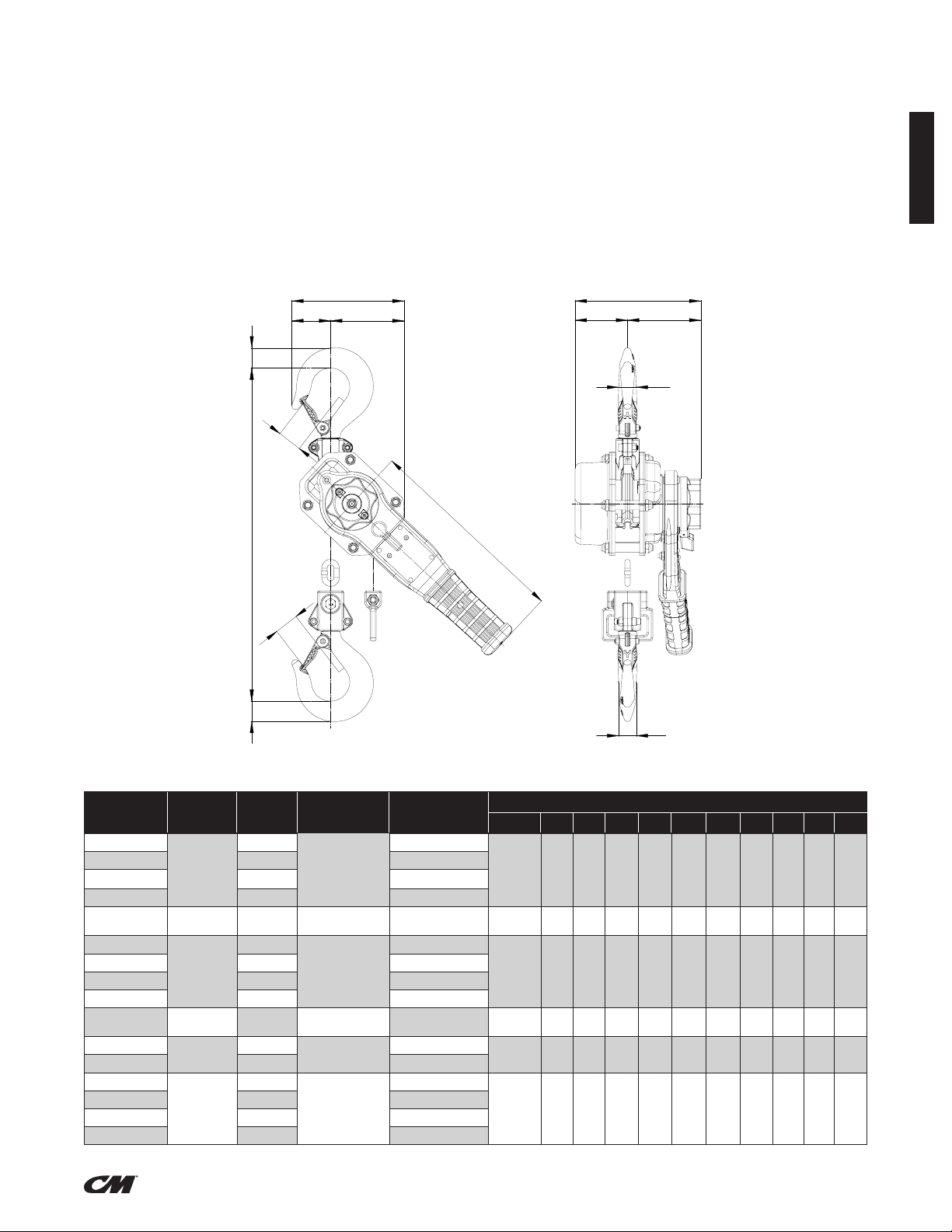
SPECIFICATIONS
F
G
H
BB
C
J
K
L
D
ENGLISH
A
C
Figure 2 – Specifications
Model
No.
5310A
5311A 10 (3) 16.05 (7.28)
5312A 15 (4.5) 18.3 (8.3)
5313A 20 (6) 20.55 (9.32)
5328A 1 5 (1.5) 51 19.84 (9)
5315A
5316A 10 (3) 23.61 (10.71)
5317A 15 (4.5) 27.12 (12.3)
5318A 20 (6) 30.62 (13.89)
5329A 2 5 (1.5) 58 35.27 (16)
5320A
5321A 10 (3) 44.29 (20.09)
5330A
5331A 10 (3) 77.18 (35.01)
5332A 15 (4.5) 91.4 (41.46)
5333A 20 (6) 105.62 (47.91)
Load Rating
(Tonnes)
3/4
1-1/2
3
6
Lift or
Reach
ft. (m)
5 (1.5)
5 (1.5)
5 (1.5)
5 (1.5)
Lever pull to Lift
Rated load (lbf)
51
77
87
92
Net Weight
lb (kg)
13.8 (6.26)
20.17 (9.15)
37.17 (16.86)
62.96 (28.56)
E
D
Dimensions in. (mm)
A (Min.) B C D E F G H J K L
11.78
0.78
1.05
0.7
10.41
4.72
1.56
(302)
13.50
(343)
14.63
(375)
16.10
(409)
17.52
(445)
22.17
(563)
(20)
0.87
(22)
1.01
(26)
1.18
(30)
1.64
(37)
1.77
(45)
(27)
1.14
(29)
1.21
(31)
1.38
(35)
1.57
(40)
1.73
(44)
(18)
0.75
(19)
0.82
(21)
0.87
(22)
1.10
(28)
1.38
(35)
(267)
10.51
(267)
10.51
(267)
14.80
(376)
14.80
(376)
14.80
(376)
(121)
5.47
(139)
5.69
(146)
6.81
(173)
7.09
(180)
9.13
(232)
(40)
1.69
(43)
1.99
(51)
1.97
(50)
2.24
(57)
2.80
(71)
3.16
(81)
3.78
(96)
3.71
(95)
4.84
(123)
4.84
(123)
6.34
(161)
5.62
(144)
6.46
(164)
6.46
(164)
7.60
(193)
7.60
(193)
7.60
(193)
2.07
(53)
2.68
(68)
2.68
(68)
3.27
(83)
3.27
(83)
3.27
(83)
3.55
(91)
3.78
(96)
3.78
(96)
4.33
(110)
4.33
(110)
4.33
(110)
4
(ENGLISH)
P/N: 192065084 Rev AA March 2020
Page 6
ENGLISH
UNPACKING
After unpacking the hoist, inspect carefully for any damage that may
have occurred during transit. Check for loose, missing or damaged
parts. Shipping damage claims must be led with carrier. The hoist
is supplied completely assembled and ready to use.
CM® REPAIR/REPLACEMENT POLICY
All Columbus McKinnon CM® Series 653-A hoists are inspected
and performance tested prior to shipment. If any properly maintained
hoist develops a performance problem, during the life of the Goods,
due to a material or workmanship defect, as veried by CM, repair
or replacement of the unit will be made to the original purchaser
without charge.
This repair/replacement policy applies only to CM Series 653-A hoists
installed, maintained and operated as outlined in this manual, and
specically excludes hoists subject to normal wear, abuse, improper
installation, improper or inadequate maintenance, hostile environmental
effects and unauthorized repairs/modications. We reserve the right
to change materials or design if, in our opinion, such changes will
improve our product. Abuse, repair by an unauthorized person,
or use of non-CM replacement parts voids the guarantee and could
lead to dangerous operation. For full Terms of Sale, see Sales Order
Acknowledgment. Also, refer to the Limitations of Warranties,
Remedies and Damages, and Indemnication and Safe Operation.
INSTALLATION
Before installing the hoist:
1. Estimate the weight of the load that is to be lifted or moved
and make sure it does not exceed the rated load of the hoist.
2. Make sure the support or sling to which the upper hook is
attached is strong enough to hold several times the weight of
the load to be lifted or moved. Be sure the hoist is solidly held
in the uppermost part of the upper hook and the latch is closed
and not in contact with the support or sling.
3. The area in which the hoist is installed must provide sufcient
room for:
a. The operator to operate the lever.
b. The operator and other personnel to stand clear
of the load at all times.
c. Firm footing for the operator.
d. Clearance between the hoist frame and any object.
The frame must be free to swivel on the upper hook.
OPERATION
If not used as directed, lever hoist may cause injury.
TO AVOID INJURY:
Use only as directed below. Read all instructions before operating
®
the CM
653-A Series hand operated lever hoist.
GENERAL
1. The hoist must be kept clean to assure proper operation.
Before use, check to be sure the load chain is clean, that there
is no foreign material in the liftwheel area and that the lever
operates freely.
2. Do not load beyond the rated capacity. Overload can cause
immediate failure or cause damage resulting in future failure,
even at less than rated capacity.
3. Do not use this hoist or any other material handling equipment
for lifting or moving people, or lifting loads over people.
4. Stand clear of all loads and warn other people of your intention
to move a load in their area.
5. Do not leave a load on the unit unattended.
6. Read warnings and instructions on the hoist before each use.
7. Do not hold the load chain while operating the hoist. Should the
hoist not operate properly, serious injury may occur.
8. Never operate the hoist when ammable materials or vapors
are present. Contact between metal parts may produce sparks
that can cause a re or explosion.
9. STAY ALERT! Watch what you are doing and use common
sense. Do not use the hoist when you are tired, distracted or
under the inuence of drugs, alcohol or medication causing
diminished control.
Malfunction of unit, rigging slip or loss of footing may cause user
to slip resulting in injury.
TO AVOID INJURY:
Always have a rm and secure footing when using the
®
CM
653-A Series hand operated lever hoist.
Attaching the hoist from an inadequate support may allow the
hoist and load to fall and cause injury and/or property damage.
TO AVOID INJURY:
Make sure the structure has sufcient strength to hold several
times the hoist weight and its rated load.
FREE CHAINING
In this mode of operation, the chain can be pulled through the hoist
in either direction by hand for quick attachment to the load.
To engage the free chaining feature, remove any load from the hoist
and move the directional lever to the (“N”) position.
5
(ENGLISH)
P/N: 192065084 Rev AA March 2020
Page 7
OPERATION (CONTINUED)
Do not take up the load chain to the point where the chain stop
or lower hook block becomes jammed against the frame.
ATTACHING THE LOAD
Attach the lower hook to the load so that it is seated in the bowl
of the hook and is not bearing against the tip of the hook or latch,
and the latch is tight against the hook tip.
Allowing the load to bear against the hook latch and/or hook tip
can result in loss of load.
TO AVOID INJURY:
Do not allow the load to bear against the hook latch and/or hook
tip. Apply load to hook bowl or saddle only.
Do not wrap the chain around the load and hook onto itself as a
choker chain sling or bring the load in contact with the hoist. Doing
this will result in the loss of the swivel effect of the hook which could
cause twisted chain and a jammed liftwheel. Also, the chain may be
damaged at the hook. Make sure the upper and lower hooks are in a
straight line and the frame is free to swivel on the upper hook.
Move directional lever to the unload position. Again, operate lever
in an up and down motion to increase the distance between hooks
and thus loosen or lower the load.
LOCKED BRAKE
If a hoist which is under load is suddenly relieved of the load by
lifting the load off of the lower hook by some other means or pulling
down walls, the brake will lock.
The brake will also lock if the lower hook block is pulled tightly
against the frame.
To unlock the brake, turn the directional lever to the unload position
and pull on the lever sharply.
Turning the Handwheel with a load attached will allow the load to
release and may cause injury.
TO AVOID INJURY:
Never turn the Handwheel when the lever hoist is under load.
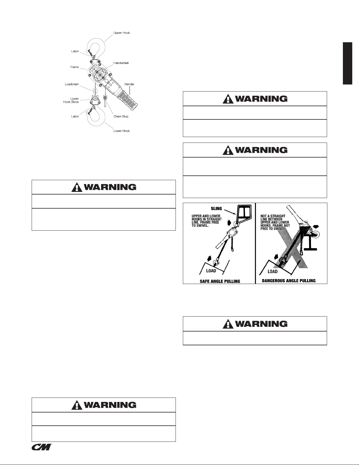
If the unit is not rigged in a straight line hook to hook manner, and
if the frame is not free to swivel, lever pull may break frame and
cause physical injury and loss of load.
TO AVOID INJURY:
Rig the unit in a straight line hook to hook manner and keep frame
free to swivel (See Figure 4).
ENGLISH
TO PULL OR LIFT THE LOAD
Operate lever in up and down motion to shorten the distance
between hooks and thus pull or lift the load.
When pulling or lifting move the load only enough to slightly load
the unit, then check to be sure that the attachments to the hooks
and load are rmly seated. Continue movement only after you are
assured the load is free of all obstructions.
The hoist has been designed for hand powered operation only. Do
not use an extension on the lever. The following Lever pulls will result
in rated capacity on the unit:
3/4t: 51 lbf / 23 kgf
1t: 51 lbf / 23 kgf
1 1/2t: 77 lbf / 35 kgf
2t: 58 lbf / 26 kgf
3t: 87 lbf / 39 kgf
6t: 92 lbf / 42 kgf
Any greater pull is an indication of either an overload or an
incorrectly maintained unit
TO LOOSEN OR LOWER LOAD
Power operation may cause structural damage or premature wear
that in turn may cause a part to break and allow the load to fall.
TO AVOID INJURY:
Operate the CM® 653-A Series lever hoist using hand power only!
(ENGLISH)
Figure 4
INSPECT HOIST
Before each use and at specied intervals as directed in the
inspection section.
Use as directed above. Failure to do so may cause injury to you
or others.
1. DO NOT exceed capacity shown on nameplate.
2. DO NOT use to lift people or loads over people.
3. DO NOT use unless the hoist’s frame and chain form a straight
line between hooks.
4. DO NOT use if the frame is in contact with any object.
5. DO NOT use if the unit is damaged or malfunctions.
6. DO NOT use extension on lever. Use hand power only.
7. DO NOT use if chain is twisted, kinked or damaged.
6
P/N: 192065084 Rev AA March 2020
Page 8
ENGLISH
a
h
b
MAINTENANCE
INSPECTION
To maintain continuous and satisfactory operation, a regular
inspection procedure must be initiated so that worn or damaged
parts can be replaced before they become unsafe. The intervals
of inspection must be determined by the individual application and
are based upon the type of service to which the hoist is subjected.
The intervals indicated as follows are based on normal service.
The inspections are divided into two general classications
designated as “frequent” and “periodic”.
FREQUENT INSPECTIONS
These inspections are usually visual examinations by the operator.
Frequent inspections are to be performed daily or before each use
and they are to include:
1. Braking mechanism for evidence of slippage.
2. Operation of the directional lever for free movement.
3. Load chain for lubricant, wear, damaged links or foreign material.
4. Hooks for damage, cracks, twists, latch engagement
and latch operation.
PERIODIC INSPECTIONS
These are visual inspections of external and internal conditions
by a designated person making records to provide the basis for
continuing evaluation of the condition of the hoist. The frequency
of periodic inspections is based upon usage as dened in ASME
B30.21. Periodic inspections should include those items
as well as the following:
1. Chain for excessive wear or stretch (See Figures 6 and 7, page 8).
2. Worn, cracked or distorted parts such as lower hook block,
upper hook block, upper hook pin, chain guide, bushings,
lever, brake cover, handwheel, directional pawl, friction hub
and lever ratchet.
3. Inspect for wear on the tip of the pawls, teeth of the ratchet,
and pockets of the liftwheel.
4. Loose or missing bolts, nuts, pins or rivets.
5. Inspect the brake components for worn, glazed or contaminated
friction discs and scoring of the friction hub and ratchet. Replace
brake ratchet assembly if contaminated, glazed or if thickness
is less than 0.256 in. (6.5 mm) for 0.75 Tonne, 1 Tonne and 1.5
Tonne, 0.307 in. (7.8 mm) for 2 Tonne, 3 Tonne and 6 Tonne.
6. Corroded, stretched or broken pawl springs, directional lever
pawl spring and lever ratchet spring.
7. Hooks – Visual inspection based upon ASME B30.10
and ASME B30.21.
8. Nameplate and Warning Labels for legibility and retention.
9. Chain stop in place and properly secured.
Any deciency should be corrected before the hoist is returned
to service. Also, the external conditions may show the need
for more detailed inspection which, in turn, may require the use
of non-destructive type testing.
Any parts deemed unserviceable are to be replaced with new parts
before the hoist is returned to service. It is very important that the
unserviceable parts are destroyed and properly disposed of to
prevent their possible future use as a repair item.
When the unit is subjected to heavy usage or dusty, gritty, moist
or corrosive atmospheric conditions, shorter time periods must be
assigned. Inspection must be made of all parts for unusual wear,
corrosion or damage, in addition to those specically mentioned
in the schedule.
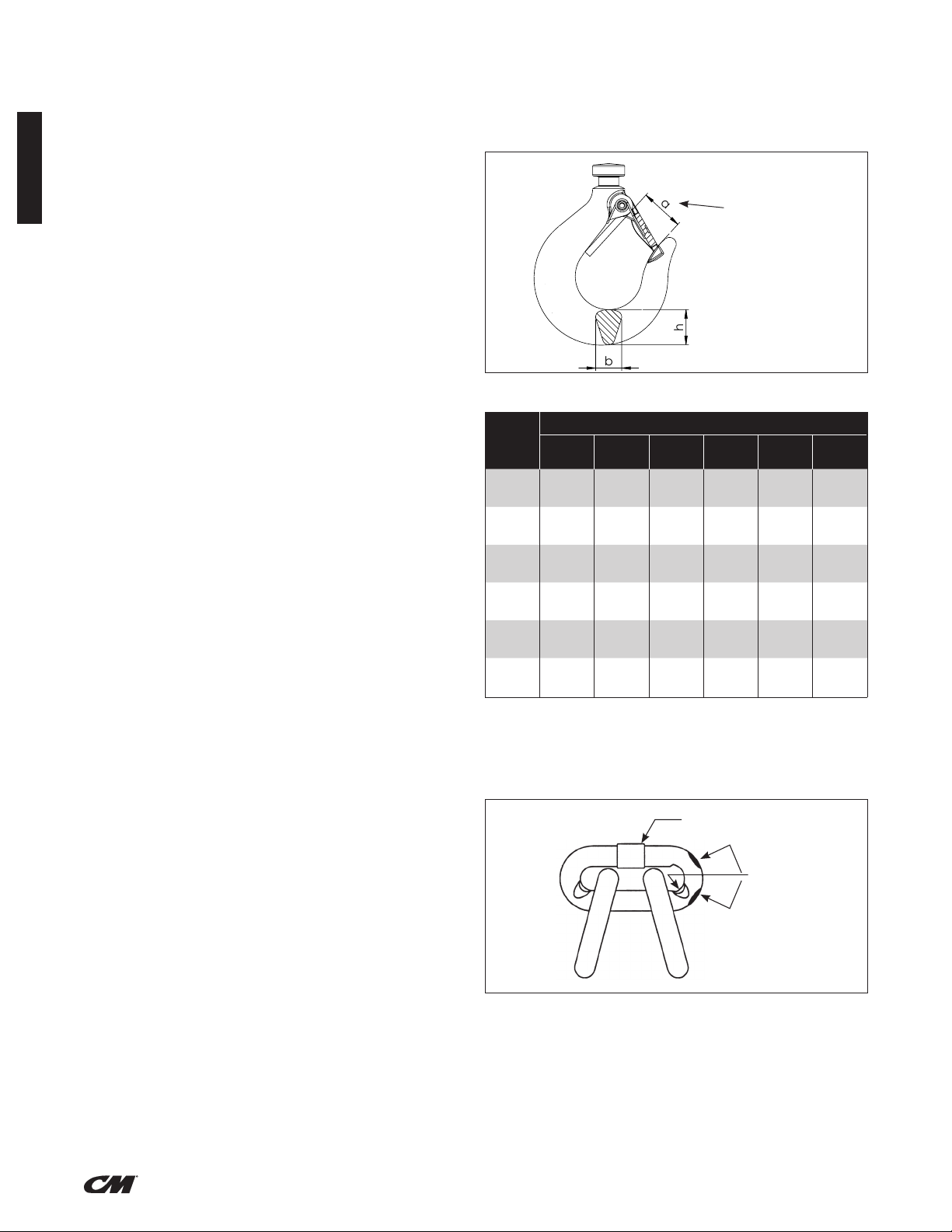
HOOK INSPECTION
Hooks damaged from chemicals, deformations or cracks, or that
have a twist from the plane of the unbent hook, excessive opening
or seat wear, must be replaced (see ASME B30.10). Also, hooks
that are opened to the extent that the latch does not engage the tip
must be replaced. Any hook that is twisted or has excessive throat
opening indicates abuse or overloading of the hoist. Other load
sustaining parts should be inspected for damage.
Check to assure the latch is not damaged or bent and that it operates
properly. It should have sufcient spring pressure to keep it tightly
against the tip of the hook and allow it to spring back to the tip when
released. If the latch does not operate properly, replace the latch.
The chart below should be used to determine when the hook must
be replaced.
Depress latch
to measure
throat opening
Figure 5 - Hook Inspection
"a"
Max.
1.17
1.25
1.38
1.51
1.73
(44)
1.90
Dimensions in. (mm)
"b" Std. "b" Min. "h" Std. "h" Min.
.59
(15)
.75
(19)
.77
(19.5)
.86
(22)
1.10
(28)
1.26
(32)
.56
(14.3)
.71
(18.1)
.73
(18.5)
.82
(20.9)
1.01
(26.6)
1.19
(30.4)
.79
(20)
.86
(22)
1.03
(26.2)
1.18
(30)
1.44
(36.6)
1.76
(44.8)
.75
(19)
.82
(20.9)
.98
(24.9)
1.12
(28.5)
1.37
(34.8)
1.68
(42.6)
Hoist
Capacity
(Tonnes)
0.75
1.0
1.5
2.0
3.0
6.0
"a" Std.
1.06
(27)
1.14
(29)
1.26
(32)
1.37
(35)
1.57
(40)
1.73
(44)
(29.7)
(31.9)
(35.2)
(38.5)
(48.4)
LOAD CHAIN
Chain should feed smoothly into and away from the hoist. If chain
binds, jumps or is noisy, rst clean and lubricate it (See Page 8).
If trouble persists, inspect chain and mating parts for wear,
distortion or other damage.
Weld
Wear In
These Areas
Figure 6 - Chain Inspection
CHAIN INSPECTION
First clean chain with a non-caustic/ nonacid type solvent
and make a link by link inspection for nicks, gouges, twisted links,
weld spatter, corrosion pits, striations (minute parallel lines),
cracks in weld areas, wear and stretching. Chain with any one
of these defects must be replaced.
Slack the portion of the chain that normally passes over the liftwheel.
Examine the interlink area for the point of maximum wear (polishing).
7
(ENGLISH)
P/N: 192065084 Rev AA March 2020
Page 9
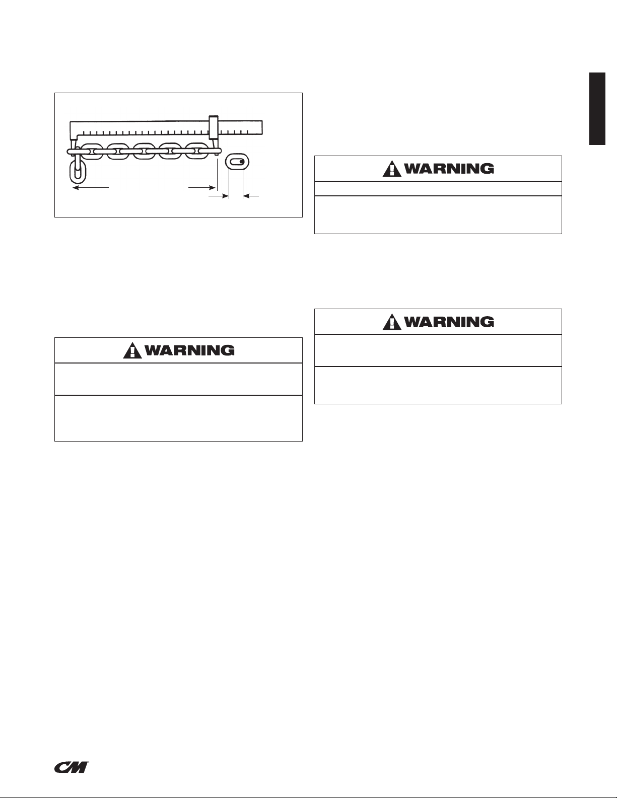
Measure and record the stock diameter at this point of the link. Then
measure stock diameter in the same area on the link that does not
pass over the liftwheel (use the link adjacent to the chain stop for this
purpose). Compare these two measurements. If the stock diameter
of the worn link is 0.010 inches (0.254mm), or more, less than the stock
diameter of the unworn link, the chain must be replaced.
Vernier Caliper
IMPORTANT: Do not use replaced chain for other purposes such
as lifting or pulling. Load chain may break suddenly without visual
deformation. For this reason, cut replaced chain into short lengths to
prevent use after disposal.
CHAIN LUBRICATION
A small amount of lubricant will greatly increase the life of load chain.
Do not allow the chain to run dry. Keep it clean and lubricate at
regular intervals with Lubriplate
Rening Co.) or equal lubricant. Normally, weekly lubrication and
cleaning is satisfactory, but under hot and dirty conditions, it may
be necessary to clean the chain at least once a day and lubricate it
several times between cleanings.
®
Bar and Chain Oil 10-R (Fiske Bros.
ENGLISH
Measure 11 Pitches
One Pitch
Figure 7 - Chain Inspection
Also check chain for stretch using a vernier caliper as shown in
Figure 7. Select an unused, unstretched section of chain (usually
at the loose end) and measure and record the length over 11 chain
links (pitches). Measure and record the same length on a worn
section of chain.
If the result (amount of stretch and wear) is greater than 0.145 inch
(3.7 mm), the chain must be replaced.
Use only a “Knife-Edge” caliper to eliminate possibility of false
reading by not measuring full pitch length.
Using other than CM® 653-A SERIES supplied load chain may
cause the chain to jam in the hoist and/or allow the chain to break
and the load to drop.
TO AVOID INJURY:
Due to size requirements and physical properties, use only CM
653-A SERIES supplied load chain in the CM
®
653-A SERIES
®
lever hoist.
Note that worn chain can be an indication of worn hoist
components. For this reason, the hoist’s frame, stripper, and
liftwheel should be examined for wear and replaced as necessary
when replacing worn chain (See DISASSEMBLY and ASSEMBLY).
Also, the load chain is specially heat treated and hardened and
should never be repaired.
Used motor oils contain known carcinogenic materials.
TO AVOID INJURY:
Never use used motor oils as a chain lubricant. Only use Lubriplate
Bar and Chain Oil 10-R as a lubricant for the load chain.
When lubricating the chain, apply sufcient lubricant to obtain
natural run-off and full coverage, especially in the interlink area.
Hoist normally requires no additional lubrication except when it has
been disassembled for cleaning or repairs.
IMPORTANT: Brake is designed to operate dry. Do not use any
grease or lubricant on the braking surfaces.
Using any grease or lubricant on the braking surfaces will cause
brake slippage and loss of load control which may result in injury
and/or property damage.
TO AVOID INJURY:
Do not use any grease or lubricant on braking surfaces. The brake
is designed to operate dry.
When lubricating parts adjacent to the brake, do not use an
excessive amount of lubricant which could seep onto the brake
surfaces.
When the hoist is disassembled for cleaning or repairs, the following
locations should be lubricated with approximately 1 . oz. per hoist
of Molykote BR-2-S (Dow Corning), Molytex #2 (Texaco) or TopMoly
(Topsall) grease or equal lubricant: gears, liftwheel bushings, exterior
of pinion shaft, surfaces of frame bushings and surface of gear cover
bushings. Be sure to thoroughly clean the old grease from these
parts before re-lubricating.
IMPORTANT: To ensure long life and top performance, be sure to
lubricate the various parts of the hoist using the lubricants specied
above. If desired, these lubricants can be purchased from Columbus
McKinnon (See Figure 13, page 10).
®
8
(ENGLISH)
P/N: 192065084 Rev AA March 2020
Page 10
ENGLISH
Columbus McKinnon
Industrial Products GmbH
Yale-Allee 30
42329 Wuppertal / Germany
3
2
5
C
D
4
6
7
8
A
B
Edges According to
DIN 6784
Specified Tolerances
ISO 8015
Material No:
Standard:
Kettenverlauf
Chain installation
KON7
05/09/2019
Description:
mm
Dimensional Units
General Tolerances
ISO 2768-mk
Material:
Modeled:
First Angle Projection
MAINTENANCE (CONTINUED)
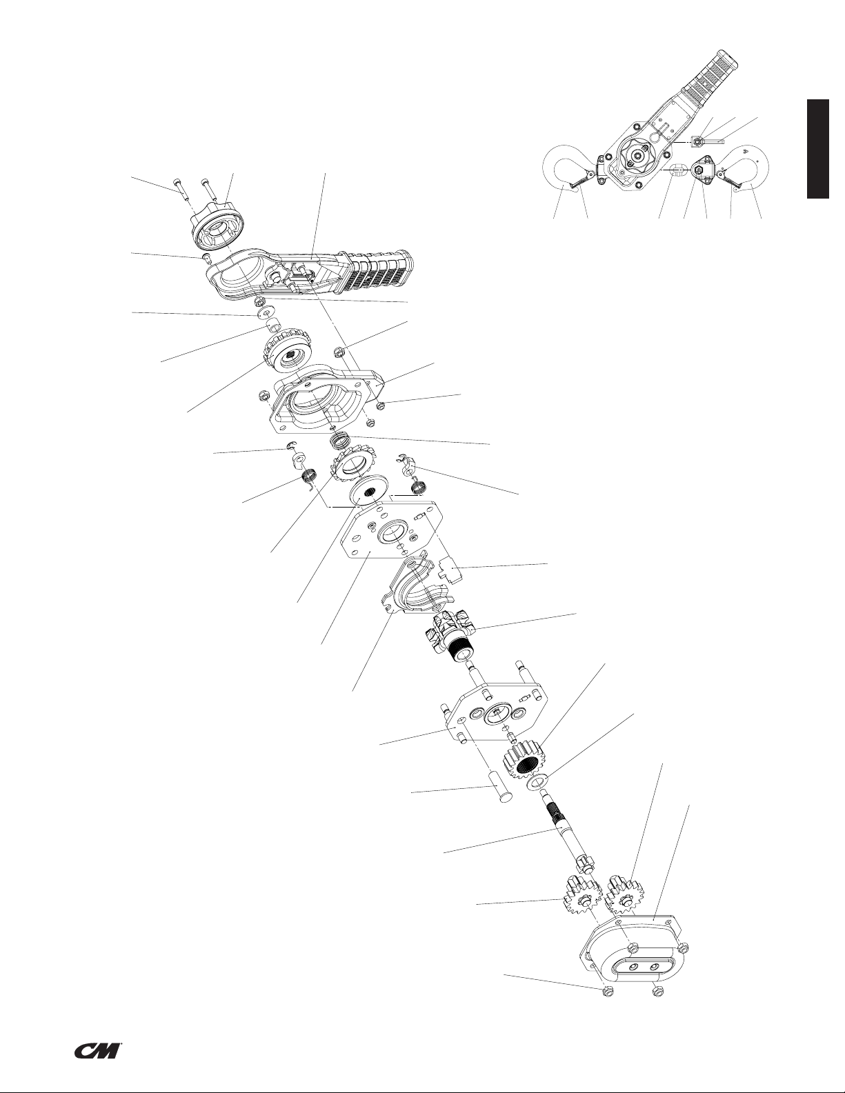
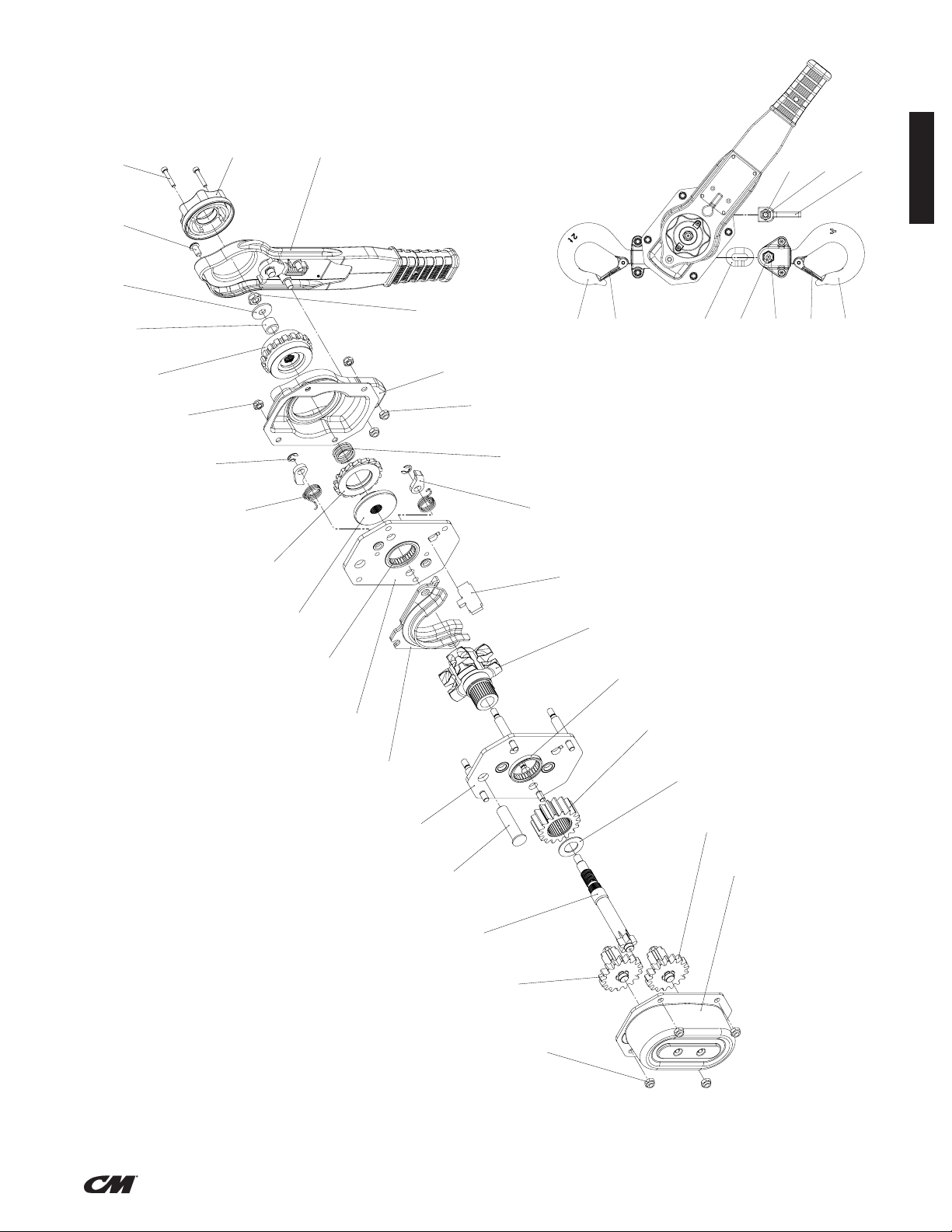
DISASSEMBLY AND ASSEMBLY
The parts illustration and list in the repair parts section show the
general arrangement and name of the parts of the CM® 653-A
SERIES lever hoist. These should be used when disassembling and
re-assembling the units so that all parts are properly installed.
DISASSEMBLY
To replace the liftwheel or stripper, completely disassemble the unit:
remove the chain (See REPLACING LOAD CHAIN, page 11) and then
remove the following: T2 Cylinder Screws M5x30, Handwheel, Lever
Handle Assembly (Button Head Screw and 2 Lock Nuts) Center Lock
Nut, Washer, Bushing, Ratchet Wheel (or Overload Assembly), Brake
Side Cover (4 Lock Nuts) Pressunre Spring, Ratchet Disc Assembly,
Disc Hub, Lever Side Plate Assembly, Chain Guide, Stripper.
On the gear side, remove the following: 4 Lock Nuts, Gear Case
Assembly, Spur Gear Assembly, Drive Shaft, Drive Shaft Washer,
Load Gear, Top Hook Shaft, Upper Hook Assembly, Gear Side Plate
Assembly
ASSEMBLY
Prior to re-assembly, check all parts for excessive wear, cracks and
distortion. Replace parts as necessary and then re-assemble the unit
in reverse to the order given above
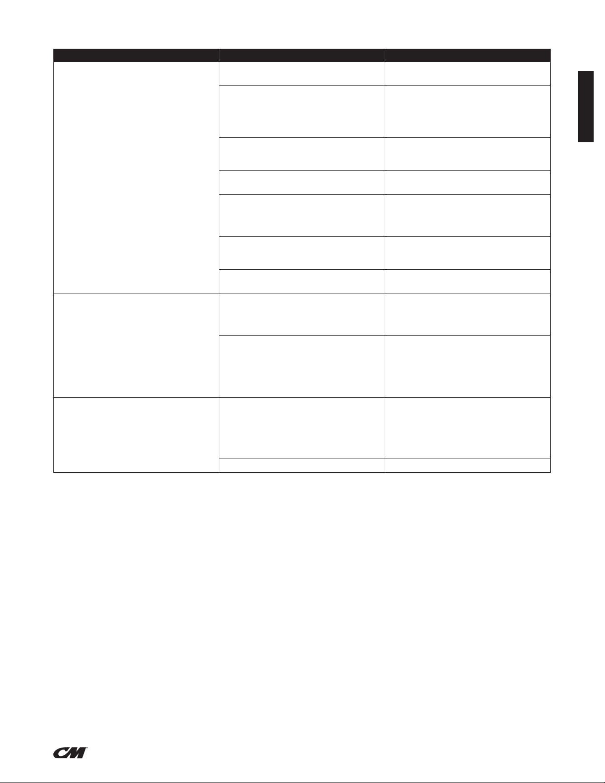
GEAR TIMING
When assembling gears, they must be orientated with the timing
marks orientated as shown. (use gure “Gear Timing”) Note: For 1t
+ 1.5t Tonne units, orientation of pinion/gear assemblies A and B are
not relevant providing the timing marks are orientated as shown and
one of each (A & B) assembly is present.
Chain Installation Single Reeved (0.75 – 3 Tonne)
Chain installation Double Reeved (6 Tonne)
Timing Marks Timing Marks
Figure 10 - Gear Timing
(0.75t + 1t + 1.5t)
Figure 11 - Gear Timing
(2t + 3t + 6t)
REPLACING LOAD CHAIN
To replace the load chain, remove the lower hook block and chain
stop from the chain. Move the directional lever to the neutral “N” and
pull the old chain out of the hoist. Feed a length of soft wire through
one side of the chain guide and over the liftwheel until it comes out
on the other side of the chain guide. Attach the wire to the end of the
new chain. Position the chain so that the rst link to enter the chain
guide will be an upstanding link and the welds on all upstanding
links will be away from the liftwheel. Pull on the wire until the chain
engages the liftwheel. Turn the handwheel while pulling on the wire,
until the chain comes out of the chain guide. Pull the chain through
and remove the wire. Attach the lower hook block to the chain that is
directly below the upper hook.
9
(ENGLISH)
P/N: 192065084 Rev AA March 2020
Page 11

RECOMMENDED SPARE PARTS
Ratchet Disc Assembly
Latch Kit
Upper & Lower Hook Assembly
Alterations or modications of equipment and use of any parts
other than CM
®
653-A Series lever hoist repair parts can lead to
dangerous operation and injury.
TO AVOID INJURY:
Do not alter or modify equipment. Do use only CM
®
653-A Series
provided replacement parts.
PREVENTATIVE MAINTENANCE
In addition to the inspection procedures, a preventative maintenance program should be established to prolong the useful life of the hoist
and maintain its dependability and continued safe use. The program should include the periodic inspections with particular attention being
paid to the lubrication of various components using the recommended lubricants (See Figure 13).
TESTING
Prior to initial use, all repaired or used hoists that have not been operated for the previous 12 months shall be tested by the user for proper
operation. Test the unit rst in the unloaded state and then with a light load of 100 pounds (45 kg.) times the number of load supporting parts
of load chain to be sure it operates properly and the brake holds the load when the lever is released; then test with a load of 125% of rated
capacity.
In addition, hoists in which load sustaining parts have been replaced must be tested with 125% of rated capacity by or under the direction of
a designated person and a written report prepared for record purposes.
NOTE: For additional information on Inspection and Testing refer to ASME B30.21 “Manually Lever Operated Hoists” obtainable from ASME
Order Department, 22 Law Drive, Box 2300, Faireld, NJ 07007-2300, U.S.A.
INSPECTOR’S REPORT
ITEM REMARKS (LIST DEFICIENCIES AND RECOMMENDED ACTION)
ENGLISH
Inspector’s
Signature
Date
Inspected Approved by Date
Figure 12 - Recommended Inspector’s Report
RECOMMENDED LUBRICATION SCHEDULE*
®
653-A SERIES HAND OPERATED LEVER HOISTS
CM
COMPONENT TYPE OF LUBRICANT ORDER PART NO. TYPE OF SERVICE AND FREQUENCY OF LUBRICATION
Load Chain Oil (See page 8) 28619 (1 gal. can)
Gears, Bushings, Liftwheel
bushings & Pinion shaft
(*) This lubrication schedule is based on a hoist operating in normal environment conditions. Hoists operating in adverse atmospheres containing excessive heat, corrosive fumes or vapors,
abrasive dust, etc., should be lubricated more frequently.
Grease (See page 8) 28618 (1 lb. can) When hoist is disassembled for cleaning or repairs
HEAVY NORMAL INFREQUENT
Daily Weekly Monthly
Figure 13 - Recommended Lubrication Schedule
10
(ENGLISH)
P/N: 192065084 Rev AA March 2020
Page 12
MAINTENANCE (CONTINUED)
ENGLISH
INSPECTION AND MAINTENANCE CHECK LIST
HAND OPERATED LEVER HOIST
Type of Hoist ________________________________________________ Capacity (Tons) ________________________________________________
Location ____________________________________________________ Original Installation Date _______________________________________
Manufacturer _________________________________________________ Manufacturer’s Serial No. _______________________________________
Frequency of Inspection
Frequent Periodic
Item
Daily
Brake Mechanism * * Slippage or excessive drift. Worn, glazed or contaminated
Directional Lever * * Binding and does not move freely.
Retractable Handle * * Possible Deficiencies: Binding and does not move freely.
Load Chain * * Inadequate lubrication, excessive wear or stretch, cracked
Hooks * * Excessive throat opening, twisted, damaged or non-operating
Lower Hook Block, Upper Hook Block,
Upper Hook Pin, Chain Guide, Bushings,
Gears, Pinion and Friction Hub
Tip of Pawls and Lever Pawl Teeth
of Ratchet and Lever Ratchet
Pockets of Liftwheel, Stripper
and Side Plates
Nuts, Bolts, Pins and Rivets * Cracks, bending, loose, stripped threads.
Pawl Springs, Directional Pawl Spring,
and Spring
Chain Stop * Missing, cracked, not secured to chain, not
Nameplate, Warning Labels
and Free Chaining
NOTE: Refer to Maintenance and Inspection Sections of this manual for further details.
Every 3 Months
to Annually as
defined per
ASME B30.21
friction discs. Thickness of brake ratchet assembly less
than 7mm
Cracks, distortion, excessive wear, corrosion or build-up
of foreign material.
damaged or twisted links, corroded or clogged with foreign
material.
hook latch, chemical damage. Cracks (Use dye penetrant,
magnetic or other suitable detection method at least once a
year).
* Cracks, distortion, excessive wear, corrosion or build-up
of foreign material.
* Cracks, distortion, excessive wear, corrosion or build-up
of foreign material.
* Cracks, distortion, excessive wear, corrosion or build-up
of foreign material.
* Corrosion, stretched or broken.
properly positioned.
* Missing, Damaged or illegible.
Possible Deficiencies OK
Action
Required
FREQUENCY OF INSPECTION
Frequent - Indicates items requiring inspection daily or before each use. These inspections may be performed by the operator
Periodic - Indicates items requiring inspection every three months. Inspections to be performed by or under the direction of a properly
NOTE: This inspection and maintenance check list is in accordance with our interpretation of the requirements of the Safety Standard
for Lever Hoists ASME B30.21. It is, however, the ultimate responsibility of the employer/user to interpret and adhere to the applicable
requirements of this safety standard.
Figure 14 — Recommended Inspection and Maintenance Check List
if properly designated.
designated person. The exact period of inspection will depend on frequency and type of usage. Determination of this period
will be based on the user’s experience. It is recommended that the user begin with a quarterly inspection and extend the
periods to semi-annually or annually based on the user’s quarterly experience.
11
(ENGLISH)
P/N: 192065084 Rev AA March 2020
Page 13
TROUBLESHOOTING CHART
Symptom Possible Cause(s) Corrective Action
Hoist is hard to operate in either direction. 1. Load chain worn long to gauge, thus binding
between liftwheel and chain guide.
2. Load chain rusty, corroded or clogged with
foreign matter such as cement or mud.
3. Bushings clogged with matter such as cement
or dust.
4. Lever binding. 4. Clean by removing any foreign matter which may
5. Brake parts corroded or clogged with
foreign matter.
6. Liftwheel pockets clogged with foreign matter or
worn excessively causing chain to bind between
liftwheel and chain guide.
7. Liftwheel twisted or bent - gear teeth bent. 7. Excessive overload had been applied.
Hoist is hard to operate in down direction. 1. Brake parts corroded or clogged with
foreign matter.
2. Chain binding. 2. Check chain, (See page 7) and replace if worn
Hoist is hard to operate in up direction. 1. Chain binding. 1. Check chain, (See page 7) and replace if worn
2. Overload. 2. Reduce load or use correct capacity unit.
1. Check chain, (See page 7) and replace
if worn excessively.
2. Clean chain by tumble polishing or using a
non-acid or non-caustic type solvent. Check
chain for gouges, damaged or bent links.
Lubricate with Lubriplate
®
Bar and Chain Oil
10-R (Fiske Bros. Refining Co.) or equal lubricant.
3. Disassemble and clean liftwheel bushings and
bushings in gear cover and side plate (gear side).
Any parts worn excessively should be replaced.
be between the lever and the brake cover.
5. Disassemble brake and clean thoroughly (by wiping
with a cloth - not by washing in a solvent). Replace
ratchet assembly if too gummy, worn or scored.
Keep brake surfaces clean and dry.
6. Clean out pockets and use if not worn excessively.
Replace liftwheel if pockets are worn.
Replace damaged parts.
1. Disassemble brake and clean thoroughly (by wiping
with a cloth - not by washing in a solvent). Replace
ratchet assembly if too gummy, worn or scored.
Keep brake surfaces clean and dry.
excessively. Clean chain by tumble polishing or using a non-acid or non-caustic type solvent. Check
chain for gouges, damaged or bent links. Lubricate
with Lubriplate
®
Bar and Chain Oil 10-R (Fiske
Bros. Refining Co.) or equal lubricant.
excessively. Clean chain by tumble polishing or using a non-acid or non-caustic type solvent. Check
chain for gouges, damaged or bent links. Lubricate
with Lubriplate
®
Bar and Chain Oil 10-R (Fiske
Bros. Refining Co.) or equal lubricant.
ENGLISH
12
(ENGLISH)
P/N: 192065084 Rev AA March 2020
Page 14
ENGLISH
REPAIR PARTS LIST
Using “Commercial” or other manufacturer’s parts to repair the
®
CM
653-A Series may cause load loss.
TO AVOID INJURY:
Use only CM supplied replacement parts. Parts may look alike but
CM parts are made of specic materials or processed to achieve
specic properties
ORDERING INSTRUCTIONS
The following information must accompany all correspondence
orders for replacement parts:
1. Hoist Model Number from identication plate.
2. Serial number of the hoist stamped below identication plate.
3. Length of lift.
4. Part number of part from parts list.
5. Number of parts required.
6. Part name from parts list.
NOTE: When ordering replacement parts, it is recommended
that consideration be given to the need for also ordering such
items as nuts, bolts, cotter pins, etc. These items may be
damaged or lost during disassembly or just unfit for future
use because of deterioration from age or service.
13
(ENGLISH)
P/N: 192065084 Rev AA March 2020
Page 15
CM® 653-A SERIES HAND OPERATED LEVER HOIST
Part
Number
653A-0001 653-A Gear Kit 0.75T
- 15 LOAD GEAR 1
- 16 SPUR GEAR ASSEMBLY 2
- 17 DRIVE SHAFT WASHER 1
- 8 DRIVE SHAFT 1
653A-0002 653-A Gear Kit 1T & 1.5T
- 15 SPUR GEAR ASSEMBLY 'A' 1
- 16 SPUR GEAR ASSEMBLY 'B' 1
- 17 DRIVE SHAFT WASHER 1
- 19 LOAD GEAR 1
- 8 DRIVE SHAFT 1
653A-0003 653-A Gear Kit 2T, 3T & 6T
- 18 LOAD GEAR 1
- 16 SPUR GEAR ASSEMBLY 2
- 22 DRIVE SHAFT WASHER 1
- 8 DRIVE SHAFT 1
BAN-0010 LOAD SHEAVE KIT 0.75T
- 18 Load Sheave 1
- 17 Drive Shaft Washer 1
BAN-0011 LOAD SHEAVE KIT 1T & 1.5T
- 18 Load Sheave 1
- 17 Drive Shaft Washer 1
BAN-0012 LOAD SHEAVE KIT 2T, 3T & 6T
- 17 Load Sheave 1
- 20 Load Gear Bearing 2
653A-0020 653-A GEAR SIDE PLATE KIT 0.75T
- 1 GEAR SIDE PLATE; ASSY 1
- 22 BUTTON HEAD SCREW 1
653A-0021 653-A GEAR SIDE PLATE KIT 1T & 1.5T
- 1 GEAR SIDE PLATE, ASSY. 1
- 23 BUTTON HEAD SCREW 1
653A-0022 653-A GEAR SIDE PLATE KIT 2T, 3T & 6T
- 1 GEAR SIDE PLATE, ASSY. 1
- 23 BUTTON HEAD SCREW 1
- 20 LIFTWHEEL BEARING (OUTER RING + ROLLERS) 2
653A-0023 653-A LEVER SIDE PLATE KIT 0.75T
- 22 BUTTON HEAD SCREW 1
- 2 LEVER SIDE PLATE; ASSY. 1
653A-0024 653-A LEVER SIDE PLATE KIT 1T & 1.5T
- 23 BUTTON HEAD SCREW 1
- 2 LEVER SIDE PLATE, ASSY. 1
653A-0025 653-A LEVER SIDE PLATE KIT 2T, 3T & 6T
- 12 CYL. SCREW TO M8 - 13 x 22 4
- 23 BUTTON HEAD SCREW 1
- 20 LIFTWHEEL BEARING (OUTER RING + ROLLERS) 2
653A-0030 653-A STRIPPER KIT 0.75T
- 12 BUSHING 1
- 13 CHAIN GUIDE 1
- 14 STRIPPER 1
653A-0031 653-A STRIPPER KIT 1T & 1.5T
- 12 BUSHING 1
- 13 CHAIN GUIDE 1
- 14 STRIPPER 1
Manual
#
Description Qty.
Part
Number
653A-0032 653-A STRIPPER KIT 2T, 3T & 6T
- 12 BUSHING 1
- 13 CHAIN GUIDE 1
- 14 STRIPPER 1
653A-0040 653-A CHANGE GEAR KIT 0.75T
- 12 BUSHING 1
- 6 CHANGE OVER GEAR 1
653A-0041 653-A CHANGE GEAR KIT 1T & 1.5T
- 12 BUSHING 1
- 6 CHANGE OVER GEAR 1
653A-0042 653-A CHANGE GEAR KIT 2T, 3T & 6T
- 12 BUSHING 1
- 6 CHANGE OVER GEAR 1
653A-0050 653-A SPRING KIT 0.75T, 1T & 1.5T
- 11 PRESSURE SPRING 1
- 20 PAWL SPRING 2
653A-0051 653-A SPRING KIT 2T, 3T & 6T
- 11 PRESSURE SPRING 1
- 15 PAWL SPRING 2
TOR-0050 - 653-A CHAIN STOP KIT 0.75T
- 31 LOCK RING 1
- 34 LOCK RING SCREW 1
- 35 LOCK NUT M6 1
TOR-0051 653-A CHAIN STOP KIT 1T & 1.5T
- 38 LOCK RING 1
- 41 LOCK RING SCREW 1
- 42 M8 LOCK NUT 1
TOR-0052 653-A CHAIN STOP KIT 2T & 3T
- 32 LOCK RING 1
- 35 LOCK RING SCREW 1
- 36 LOCK NUT M10 2
TOR-0052 653-A CHAIN STOP KIT 6T
- 32 LOCK RING 1
- 35 LOCK RING SCREW 1
- 37 LOCK NUT M10 1
653A-0070 653-A RATCHET KIT 0.75T, 1T & 1.5T
- 9 DISC HUB 1
- 10 RATCHET DISC ASSEMBLY 1
- 11 PRESSURE SPRING 1
653A-0071 653-A RATCHET KIT 2T, 3T & 6T
- 9 DISC HUB 1
- 10 RATCHET DISC ASSEMBLY 1
- 11 PRESSURE SPRING 1
653A-0080 653-A BRAKE COVER KIT 0.75T
- 4 HOUSING COVER 1
- 24 LOCK NUT M8 4
653A-0081 653-A BRAKE COVER KIT 1T & 1.5T
- 4 HOUSING COVER 1
- 25 LOCK NUT M8 4
653A-0082 653-A BRAKE COVER KIT 2T, 3T & 6T
- 4 HOUSING COVER 1
- 26 LOCK NUT M8 4
Manual
#
Description Qty.
ENGLISH
14
(ENGLISH)
P/N: 192065084 Rev AA March 2020
Page 16
CM® 653-A SERIES HAND OPERATED LEVER HOIST
ENGLISH
Part
Number
653A-0083 653-A GEAR COVER KIT 0.75T
- 3 GEAR CASE ASSEMBLY 1
- 24 LOCK NUT M8 4
653A-0084 653-A GEAR COVER KIT 1T & 1.5T
- 3 GEAR CASE ASSEMBLY 1
- 25 LOCK NUT M8 4
653A-0085 653-A GEAR COVER KIT 2T, 3T & 6T
- 3 GEAR CASE ASSEMBLY 1
- 26 LOCK NUT M8 4
653A-0090 653-A HARDWARE KIT 0.75T
- 27 E-CLIP 2
- 25 LOCK NUT M6 2
- 23 CYLINDER SREW 2
- 24 LOCK NUT M8 9
- 26 WASHER 1
- 22 BUTTON HEAD SCREW 1
653A-0090 653-A HARDWARE KIT 1T & 1.5T
- 28 E-CLIP 2
- 26 LOCK NUT M6 2
- 24 CYLINDER SREW 2
- 25 LOCK NUT M8 9
- 27 WASHER 1
- 23 BUTTON HEAD SCREW 1
653A-0091 653-A HARDWARE KIT 2T, 3T & 6T
- 28 E-CLIP 2
- 25 LOCK NUT M10 1
- 24 CYLINDER SREW 2
- 26 LOCK NUT M8 10
- 27 WASHER 1
- 23 BUTTON HEAD SCREW 1
- 22 DRIVE SHAFT WASHER 1
653A-0100 653-A PAWL KIT 0.75T
- 20 PAWL SPRING 2
- 21 PAWL 2
- 27 E-CLIP 2
653A-0100 653-A PAWL KIT 1T & 1.5T
- 20 PAWL SPRING 2
- 21 PAWL 2
- 28 E-CLIP 2
653A-0101 653-A PAWL KIT 2T, 3T & 6T
- 15 PAWL SPRING 2
- 21 PAWL 2
- 28 E-CLIP 2
653A-0110 653-A HANDWHEEL KIT 0.75T
- 23 CYLINDER SREW 2
- 7 HAND WHEEL 1
- 12 BUSHING 1
- 26 WASHER 1
- 10 RATCHET DISC ASSEMBLY 1
- 24 LOCK NUT M8 1
Manual
#
Description Qty.
Part
Number
653A-0110 653-A HANDWHEEL KIT 1T & 1.5T
- 24 CYLINDER SREW 2
- 7 HAND WHEEL 1
- 12 BUSHING 1
- 27 WASHER 1
- 10 RATCHET DISC ASSEMBLY 1
- 25 LOCK NUT M8 1
653A-0111 653-A HANDWHEEL KIT 2T, 3T & 6T
- 24 CYLINDER SREW 2
- 7 HAND WHEEL 1
- 12 BUSHING 1
- 27 WASHER 1
- 10 RATCHET DISC ASSEMBLY 1
- 25 LOCK NUT M10 1
BAN-0120 653-A UPPER HOOK ASSEMBLY KIT 0.75T
- 28 Upper Hook Assembly 1
653A-0120 653-A UPPER HOOK ASSEMBLY KIT 1T
- 29 TOP HOOK ASSEMBLY 1
BAN-0121 653-A UPPER HOOK ASSEMBLY KIT 1.5T
- 29 TOP HOOK ASSEMBLY 1
653A-0121 653-A UPPER HOOK ASSEMBLY KIT 2T
- 29 TOP HOOK ASSEMBLY 1
BAN-0122 653-A UPPER HOOK ASSEMBLY KIT 3T
- 29 TOP HOOK ASSEMBLY 1
BAN-0123 653-A UPPER HOOK ASSEMBLY KIT 6T
- 29 TOP HOOK ASSEMBLY 1
BAN-0130 653-A LOWER HOOK ASSEMBLY KIT 0.75T
- 29 LOWER HOOK ASSEMBLY (incl. 30, 33 + 35) 1
- 33 LOWER HOOK CHAIN BOLT 1
- 30 LATCH KIT 2
- 35 LOCK NUT M6 2
653A-0130 653-A LOWER HOOK ASSEMBLY KIT 1T
- 30 LOWER HOOK ASSEMBLY (incl. 34 + 36) 1
- 34 LOWER HOOK CHAIN BOLT 1
- 31 LATCH KIT 2
- 36 LOCK NUT M8 2
BAN-0131 LOWER HOOK ASSEMBLY KIT 1.5 TONNE
- 30 LOWER HOOK ASSEMBLY (incl. 34 + 36) 1
- 34 LOWER HOOK CHAIN BOLT 1
- 31 LATCH KIT 2
- 36 LOCK NUT M8 2
653A-0130 653-A LOWER HOOK ASSEMBLY KIT 2T
- 30 LOWER HOOK ASSEMBLY (incl. 34 + 36) 1
- 34 LOWER HOOK CHAIN BOLT 1
- 31 LATCH KIT 2
- 36 LOCK NUT M10 2
653A-0130 653-A LOWER HOOK ASSEMBLY KIT 3T
- 30 LOWER HOOK ASSEMBLY (incl. 34 + 36) 1
- 34 LOWER HOOK CHAIN BOLT 1
- 31 LATCH KIT 2
- 36 LOCK NUT M10 2
Manual
#
Description Qty.
15
(ENGLISH)
P/N: 192065084 Rev AA March 2020
Page 17
CM® 653-A SERIES HAND OPERATED LEVER HOIST
Part
Number
BAN-0133 653-A LOWER HOOK ASSEMBLY KIT 6T
- 30 LOWER HOOK ASSEMBLY (incl. 34 + 36) 1
- 34 LOWER HOOK CHAIN BOLT 1
- 31 LATCH KIT 2
- 36 LOCK NUT M12 1
653A-0140 653-A HAND GRIP KIT 0.75T
- 5 RUBBER GRIP 1
- 6 GRIP FASTENER 1
- 7 GRIP FASTENER SCREW 1
653A-0141 653-A HAND GRIP KIT 1T & 1.5T
- 5 RUBBER GRIP 1
- 6 GRIP FASTENER 1
- 7 GRIP FASTENER SCREW 1
653A-0142 653-A HAND GRIP KIT 2T, 3T & 6T
- 5 RUBBER GRIP 1
- 6 GRIP FASTENER 1
- 7 GRIP FASTENER SCREW 1
192051361 5 LEVER HANDLE ASSEMBLY (incl. NAME PLATE) 1
00002034 19 TOP HOOK SHAFT 1
192035181 N/A SPLIT RING FOR WARNING TAG 1
192061167 N/A WARNING TAG 1
635121EN 32 5.6x17.1 mm LOAD CHAIN 192051362 8 NAME PLATE 1
89033012 9 ROUND HEAD GROOVED PIN 4
53820 30 LATCH KIT 2
N09108068 22 BUTTON HEAD SCREW 1
N09102257 23 CYLINDER SREW 2
89022036 24 LOCK NUT M8 9
89022032 25 LOCK NUT M6 2
N09121200 26 WASHER 1
N09123040 27 E-CLIP 2
192063669 5 LEVER HANDLE ASSEMBLY (incl. NAME PLATE) 1
00002137 20 TOP HOOK SHAFT 1
192035181 N/A SPLIT RING FOR WARNING TAG 1
192061167 N/A WARNING TAG 1
635128EN 33 7.1x21 mm LOAD CHAIN 192063670 8 NAME PLATE 1
89033012 9 ROUND HEAD GROOVED PIN 4
N00400450 31 LATCH KIT 2
N09108068 23 BUTTON HEAD SCREW 1
N09102257 24 CYLINDER SREW 2
89022036 25 LOCK NUT M8 9
89022032 26 LOCK NUT M6 2
N09121200 27 WASHER 1
N09123040 28 E-CLIP 2
192051309 5 LEVER HANDLE ASSEMBLY (incl. NAME PLATE) 1
00002137 20 TOP HOOK SHAFT 1
192035181 N/A SPLIT RING FOR WARNING TAG 1
192061167 N/A WARNING TAG 1
635128EN 33 7.1x21 mm LOAD CHAIN -
Manual
#
Description Qty.
Individual Parts
0.75 Ton
1 Ton
1.5 Ton
Part
Number
192051310 8 NAME PLATE 1
89033012 9 ROUND HEAD GROOVED PIN 4
53821 31 LATCH KIT 2
N09108068 23 BUTTON HEAD SCREW 1
N09102257 24 CYLINDER SREW 2
89022036 25 LOCK NUT M8 9
89022032 26 LOCK NUT M6 2
N09121200 27 WASHER 1
N09123040 28 E-CLIP 2
192051685 5 LEVER HANDLE ASSEMBLY (incl. NAME PLATE) 1
00002331 19 TOP HOOK SHAFT 1
192035181 N/A SPLIT RING FOR WARNING TAG 1
192061167 N/A WARNING TAG 1
85394L 33 10x28 mm LOAD CHAIN -
192063686 8 NAME PLATE 1
89033012 9 ROUND HEAD GROOVED PIN 4
N00400451 31 LATCH KIT 2
N09108069 23 BUTTON HEAD SCREW 1
N09102257 24 CYLINDER SREW 2
89022012 25 LOCK NUT M10 1
89022036 26 LOCK NUT M8 10
N09121045 27 WASHER 1
N09123046 28 E-CLIP 2
192051465 5 LEVER HANDLE ASSEMBLY (incl. NAME PLATE) 1
00002331 19 TOP HOOK SHAFT 1
192035181 N/A SPLIT RING FOR WARNING TAG 1
192061167 N/A WARNING TAG 1
85394L 33 10x28 mm LOAD CHAIN -
192051467 8 NAME PLATE 1
89033012 9 ROUND HEAD GROOVED PIN 4
53822 31 LATCH KIT 2
N09108069 23 BUTTON HEAD SCREW 1
N09102257 24 CYLINDER SREW 2
89022012 25 LOCK NUT M10 1
89022036 26 LOCK NUT M8 10
N09121045 27 WASHER 1
N09123046 28 E-CLIP 2
192051821 5 LEVER HANDLE ASSEMBLY (incl. NAME PLATE) 1
00002331 19 TOP HOOK SHAFT 1
192035181 N/A SPLIT RING FOR WARNING TAG 1
192061167 N/A WARNING TAG 1
85394L 33 10x28 mm LOAD CHAIN -
192051820 8 NAME PLATE 1
89033012 9 ROUND HEAD GROOVED PIN 4
53940 31 LATCH KIT 2
N09108069 23 BUTTON HEAD SCREW 1
N09102257 24 CYLINDER SREW 2
89022012 25 LOCK NUT M10 1
89022036 26 LOCK NUT M8 10
N09121045 27 WASHER 1
N09123046 28 E-CLIP 2
16
(ENGLISH)
Manual
#
Description Qty.
2 Ton
3 Ton
6 Ton
P/N: 192065084 Rev AA March 2020
ENGLISH
Page 18
Columbus McKinnon
Industrial Products GmbH
Yale-Allee 30
42329 Wuppertal / Germany
24
16
16
8
17
15
19
18
14
13
2
9
27
10
21
25
4
12
5
24
7
23
3
2226
1
20
6
11
11111
1
1
1
1
1
1
1
2
1
1
1
2
2
1
2
9
2
1
2
9
3
4
5
6
7
8
10
11
By
Date
Description of change
ECN
Rev.
Edges According to
DIN 6784
Specified Tolerances
ISO 8015
Material No:
Standard:
09/13/2018
KON7
192051352
Handhebelzug, Grundgerät
Hand Lever Hoist, base unit
CM 653-A - 0,75t
KON7
KON7
Velbert
02/15/2018
02/15/2018
A1
Format
Number:
Description:
mm
Dimensional Units
General Tolerances
ISO 2768-mk
Material:
1:1
Original scale:
Original project:
Design Authority:
Approved:
Drawn:
Modeled:
First Angle Projection
Columbus McKinnon
Industrial Products GmbH
Yale-Allee 30
42329 Wuppertal / Germany
29 31
QTY.
1
1
2
1
1,8 m
1
1
2
E
B
C
D
F
5
6
7
G
ECN
Rev.
Description of change
Date
By
Modeled:
Drawn:
Approved:
Design Authority:
Original project:
Original scale:
1:1
Material:
General Tolerances
ISO 2768-mk
Dimensional Units
mm
Description:
Number:
Sheet
2
3
Format
A2
02/15/2018
02/15/2018
Velbert
KON7
KON7
653-A 0,75t
Lever Hoist w. 1,5m chain
Hebelzug m. 1,5m Kette
192051364
15.02.2018
Standard:
Material No:
Specified Tolerances
ISO 8015
Edges According to
DIN 6784
First Angle Projection
ENGLISH
PARTS DIAGRAM 0.75 TONNE
35
34
33
35
28
30
32
30
17
(ENGLISH)
P/N: 192065084 Rev AA March 2020
Page 19
Columbus McKinnon
Industrial Products GmbH
Yale-Allee 30
42329 Wuppertal / Germany
25
3
15
16
8
20
19
17
1
18
14
13
2
9
28
4
5
27
23 24
7
12
21
22
6
25
26
11
10
PART NUMBER
DESCRIPTION
QTY.
Getriebeseitenplatte, vormontiert
1
Hebelseitenplatte, komplett
1
Getriebehaube, kpl.
1
Bremshaube, kpl.
1
Hebel, kpl.
1
Sperrrad
1
Handrad
1
Antriebswelle
1
Druckscheibe
1
Sperrradscheibe, kpl.
1
Druckfeder, Freischaltung
1
Distanzbuchse
1
Kettenführung
1
Streiferblech
1
SPUR GEAR ASSEMBLY
1
00002105B
SPUR GEAR ASSEMBLY
1
DRIVE SHAFT WASHER
1
LOAD SHEAVE
1
LOAD GEAR
1
TOP HOOK SHAFT
1
PAWL SPRING
2
PAWL2Halbrundkopfschraube M6x12
1
Zylinderschraube ISO 4762 - M5x30 - 8.8
2
Sechskantmutter DIN EN ISO 10511 - M8 - 8
9
Sechskantmutter DIN EN ISO 10511 - M6 - 8
2
Scheibe ISO 7093-1 - 8,4 - Zn
1
Sicherungsscheibe DIN 6799 - 7 - FSt
2
9
2
3
4
5
6
7
8
10
11
By
Date
Description of change
ECN
Rev.
Edges According to
DIN 6784
Specified Tolerances
ISO 8015
Material No:
Standard:
19.03.2019
KON7
192063666
Handhebelzug, Grundgerät
Hand Lever Hoist, base unit
CM 653-A - 1t
KON7
KON7
Velbert
19.03.2019
19.03.2019
A1
Format
Number:
Description:
mm
Dimensional Units
General Tolerances
ISO 2768-mk
Material:
1:1
Original scale:
Original project:
Design Authority:
Approved:
Drawn:
Modeled:
First Angle Projection
Columbus McKinnon
Industrial Products GmbH
Yale-Allee 30
42329 Wuppertal / Germany
QTY.
1
1
2
1
1,8 m
1
1
2
E
B
C
D
F
6
7
G
ECN
Rev.
Description of change
Date
By
Modeled:
Drawn:
Approved:
Design Authority:
Original project:
Original scale:
1:1
Material:
General Tolerances
ISO 2768-mk
Dimensional Units
mm
Description:
Number:
Sheet
2
3
Format
A2
05.03.2019
05.03.2019
Velbert
KON7
KON7
CM 653-A - 1t
Lever Hoist
Hebelzug
192063671
KON7
05.03.2019
Standard:
Material No:
Specified Tolerances
ISO 8015
Edges According to
DIN 6784
First Angle Projection
PARTS DIAGRAM 1 TONNE
32
30
ENGLISH
36
35
31
29
33
36
31
34
18
(ENGLISH)
P/N: 192065084 Rev AA March 2020
Page 20

Columbus McKinnon
Industrial Products GmbH
Yale-Allee 30
42329 Wuppertal / Germany
25
3
15
16
8
20
19
17
1
18
14
13
2
9
28
4
5
27 23 24
7
12
21
22
6
25
26
11
ITEM NO.
PART NUMBER
DESCRIPTION
QTY.
1 192021063
Getriebeseitenplatte, vormontiert
1
2 192021062
Hebelseitenplatte, komplett
1
3 192051308
Getriebehaube, kpl.
1
4 192051306
Bremshaube, kpl.
1
5 192051309
Hebel, kpl.
1
6 192054522
Sperrrad
1
7 192049848
Handrad
1
8 192044632
Antriebswelle
1
9 192049859
Druckscheibe
1
10 192061895
Sperrradscheibe, kpl.
1
11 192049856
Druckfeder, Freischaltung
1
12 192044633
Distanzbuchse
1
13 192049944
Kettenführung
1
14 192049946
Streiferblech
1
15
00002105A
SPUR GEAR ASSEMBLY
1
16
00002105B
SPUR GEAR ASSEMBLY
1
17 00002239
DRIVE SHAFT WASHER
1
18 00002117
LOAD SHEAVE
1
19 00002109
LOAD GEAR
1
20 00002137
TOP HOOK SHAFT
1
21 00002201
PAWL SPRING
2
22 00002202
PAWL
2
23 09108068
Halbrundkopfschraube M6x12
1
24 09102257
Zylinderschraube ISO 4762 - M5x30 - 8.8
2
25 09115098
Sechskantmutter DIN EN ISO 10511 - M8 - 8
9
26 09115135
Sechskantmutter DIN EN ISO 10511 - M6 - 8
2
27 09121200
Scheibe ISO 7093-1 - 8,4 - Zn
1
28 09123040
Sicherungsscheibe DIN 6799 - 7 - FSt
2
9
2
3
4
5
6
7
8
10
11
By
Date
Description of change
ECN
Rev.
Edges According to
DIN 6784
Specified Tolerances
ISO 8015
Material No:
Standard:
KON7
192051302
Handhebelzug, Grundgerät
Hand Lever Hoist, base unit
CM 653-A - 1,5t
KON7
KON7
Velbert
02/14/2018
02/14/2018
A1
Format
Number:
Description:
mm
Dimensional Units
General Tolerances
ISO 2768-mk
Material:
1:1
Original scale:
Original project:
Design Authority:
Approved:
Drawn:
Modeled:
First Angle Projection
Columbus McKinnon
Industrial Products GmbH
Yale-Allee 30
42329 Wuppertal / Germany
QTY.
1
1
2
1
1,8 m
1
1
2
E
B
C
D
F
5
6
7
G
ECN
Rev.
Description of change
Date
By
Modeled:
Drawn:
Approved:
Design Authority:
Original project:
Original scale:
1:1
Material:
General Tolerances
ISO 2768-mk
Dimensional Units
mm
Description:
Number:
Sheet
2
3
Format
A2
02/15/2018
02/15/2018
Velbert
KON7
KON7
653-A 1,5t
Lever Hoist
Hebelzug
192051313
KON7
09/13/2018
Standard:
Material No:
Specified Tolerances
ISO 8015
Edges According to
DIN 6784
First Angle Projection
PARTS DIAGRAM 1.5 TONNE
ENGLISH
31
36
32
30
35
29
31
33
34
36
19
(ENGLISH)
P/N: 192065084 Rev AA March 2020
Page 21
Columbus McKinnon
Industrial Products GmbH
Yale-Allee 30
42329 Wuppertal / Germany
26
16
8
19
1
13
9
15
21
26
6
11
23 24
7
5
25
4
14
17
18
22
3
2
20
16
28
26
10
12
27
20
ITEM NO.
PART NUMBER
DESRIPTION
QTY.
1 00230506
Getriebeseitenplatte, vormontiert
1
2
00230507
Hebelseitenplatte, komplett
1
3
192051464
Getriebehaube, kpl.
1
4
192051462
Bremshaube, kpl.
1
5
192063685
Hebel, kpl.
1
6
192054524
Sperrrad
1
7
192050034
Handrad
1
8
192044676
Antriebswelle
1
9
192050037
Druckscheibe
1
10 192061897
Sperrradscheibe, kpl.
1
11 192050035
Druckfeder, Freischaltung
1
12 192044678
Buchse
1
13 192050029
Kettenführung
1
14 192050032
Streiferblech
1
15 192040786
Sperrhakenfeder
2
16 00002305
SPUR GEAR ASSEMBLY
2
17 00002374
LIFTWHEEL ASSEMBLY
1
18 00002309
LOAD GEAR
1
19 00002331
TOP HOOK SHAFT
1
20 00002312
LIFTWHEEL BEARING
2
21 00002336
PAWL
2
22 00002361
DRIVE SHAFT WASHER
1
23 09108069
Halbrundkopfschraube M8x16
1
24 09102257
Zylinderschraube ISO 4762 - M5x30 - 8.8
2
25 09115036
Sechskantmutter DIN 985 - M10 - 8
1
26 09115098
Sechskantmutter DIN EN ISO 10511 - M8 - 8
10
27
09121045
Scheibe ISO 7093-1 - 10,5 - Zn
1
28 09123046
Sicherungsscheibe DIN 6799 - 8 - FSt
2
9
1
2
3
4
5
6
7
8
10
11
K
G
B
C
D
E
F
H
JJ
By
Date
Description of change
ECN
Rev.
Edges According to
DIN 6784
Specified Tolerances
ISO 8015
Material No:
Standard:
19.03.2019
KON7
192063683
Handhebelzug, Grundgerät
Hand Lever Hoist, base unit
CM 653-A - 2t
KON7
KON7
Velbert
19.03.2019
19.03.2019
A1
Format
1
3
Sheet
Number:
Description:
mm
Dimensional Units
General Tolerances
ISO 2768-mk
Material:
1:10
Original scale:
Original project:
Design Authority:
Approved:
Drawn:
Modeled:
First Angle Projection
PARTS DIAGRAM 2 TONNE
Columbus McKinnon
Industrial Products GmbH
Yale-Allee 30
42329 Wuppertal / Germany
32
E
B
C
D
F
6
7
G
ECN
Rev.
Description of change
Date
By
Modeled:
Drawn:
Approved:
Design Authority:
Original project:
Original scale:
1:10
Material:
General Tolerances
ISO 2768-mk
Dimensional Units
mm
Description:
Number:
Sheet
2
3
Format
A2
11.03.2019
11.03.2019
Velbert
KON7
KON7
CM 653-A - 2t
Lever Hoist w. 1,5m chain
Hebelzug m. 1,5m Kette
192063687
KON7
11.03.2019
Standard:
Material No:
Specified Tolerances
ISO 8015
Edges According to
DIN 6784
First Angle Projection
29
31
33
34
36
35
36
ENGLISH
30
31
20
(ENGLISH)
P/N: 192065084 Rev AA March 2020
Page 22
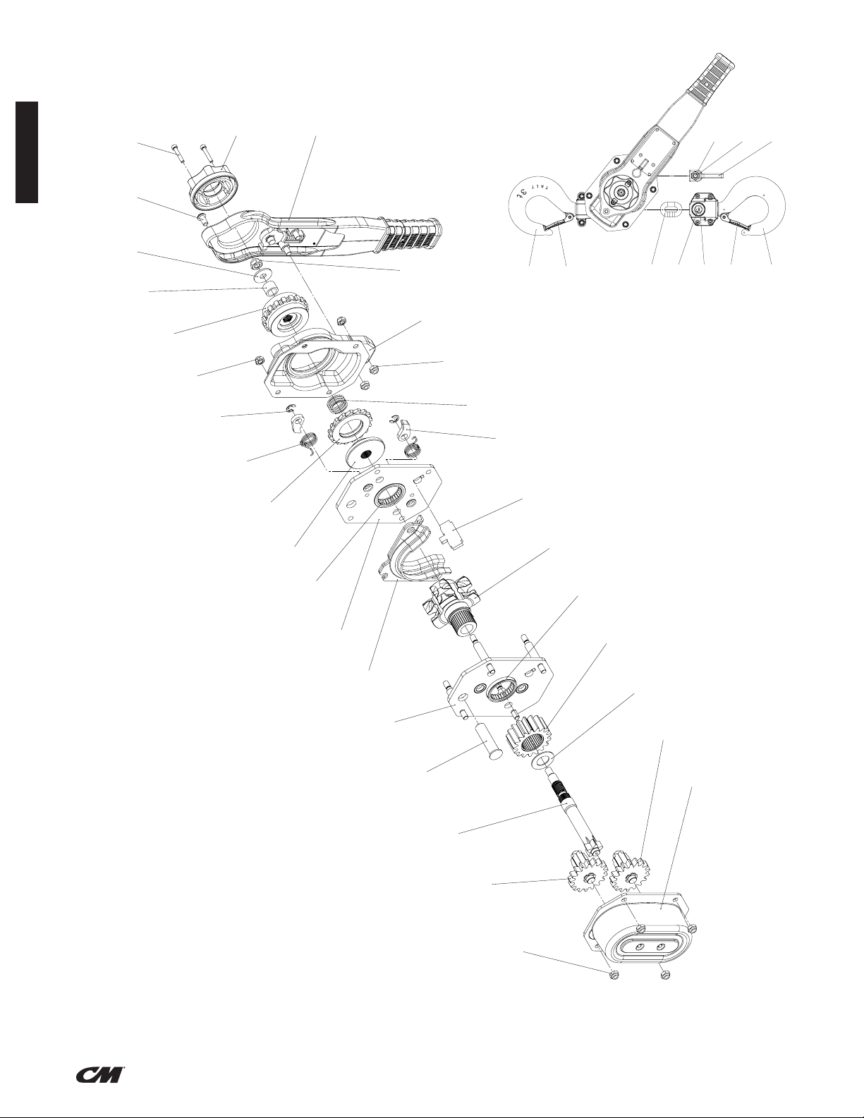
Columbus McKinnon
Industrial Products GmbH
Yale-Allee 30
42329 Wuppertal / Germany
26
16
8
19
1
13
9
15
21
26
6
11
23 24
7
5
25
4
14
17
18
22
3
2
20
16
28
26
10
12
27
20
ITEM NO.
PART NUMBER
DESRIPTION
QTY.
1 00230506
Getriebeseitenplatte, vormontiert
1
2 00230507
Hebelseitenplatte, komplett
1
3 192051464
Getriebehaube, kpl.
1
4
192051462
Bremshaube, kpl.
1
5 192051465
Hebel, kpl.
1
6
192054524
Sperrrad
1
7
192050034
Handrad
1
8
192044676
Antriebswelle
1
9
192050037
Druckscheibe
1
10 192061897
Sperrradscheibe, kpl.
1
11 192050035
Druckfeder, Freischaltung
1
12 192044678
Buchse
1
13 192050029
Kettenführung
1
14 192050032
Streiferblech
1
15 192040786
Sperrhakenfeder
2
16 00002305
SPUR GEAR ASSEMBLY
2
17 00002374 LIFTWHEEL ASSEMBLY 1
18 00002309
LOAD GEAR
1
19 00002331
TOP HOOK SHAFT
1
20 00002312
LIFTWHEEL BEARING
2
21 00002336
PAWL
2
22 00002361
DRIVE SHAFT WASHER
1
23 09108069
Halbrundkopfschraube M8x16
1
24 09102257
Zylinderschraube ISO 4762 - M5x30 - 8.8
2
25 09115036
Sechskantmutter DIN 985 - M10 - 8
1
26 09115098
Sechskantmutter DIN EN ISO 10511 - M8 - 8
10
27
09121045
Scheibe ISO 7093-1 - 10,5 - Zn
1
28 09123046
Sicherungsscheibe DIN 6799 - 8 - FSt
2
9
2
3
4
5
6
7
8
10
11
K
G
A
B
C
D
E
F
H
JJ
By
Date
Description of change
ECN
Rev.
Edges According to
DIN 6784
Specified Tolerances
ISO 8015
Material No:
Standard:
04/12/2019
KON7
192051457
Handhebelzug, Grundgerät
Hand Lever Hoist, base unit
CM 653-A - 3,0t
KON7
KON7
Velbert
02/19/2018
02/19/2018
A1
Format
1
3
Sheet
Number:
Description:
mm
Dimensional Units
General Tolerances
ISO 2768-mk
Material:
1:10
Original scale:
Original project:
Design Authority:
Approved:
Drawn:
Modeled:
First Angle Projection
PARTS DIAGRAM 3 TONNE
Columbus McKinnon
Industrial Products GmbH
Yale-Allee 30
42329 Wuppertal / Germany
E
A
B
C
D
F
6
7
G
ECN
Rev.
Description of change
Date
By
Modeled:
Drawn:
Approved:
Design Authority:
Original project:
Original scale:
1:10
Material:
General Tolerances
ISO 2768-mk
Dimensional Units
mm
Description:
Number:
Sheet
2
3
Format
A2
02/20/2018
02/20/2018
Velbert
KON7
KON7
653-A 3t
Lever Hoist w. 1,5m chain
Hebelzug m. 1,5m Kette
192051469
KON7
01/30/2019
Standard:
Material No:
Specified Tolerances
ISO 8015
Edges According to
DIN 6784
First Angle Projection
ENGLISH
29
31
33
35
36
34
31
32
36
30
21
(ENGLISH)
P/N: 192065084 Rev AA March 2020
Page 23
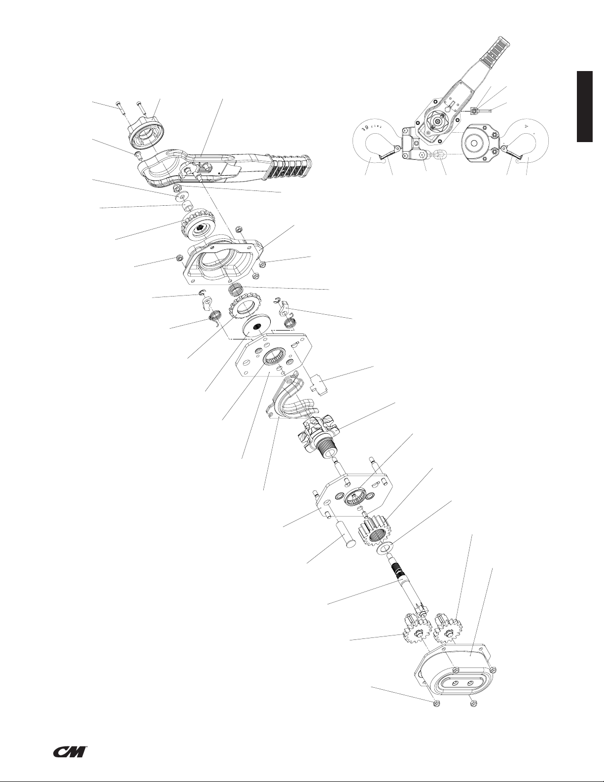
Columbus McKinnon
Industrial Products GmbH
Yale-Allee 30
42329 Wuppertal / Germany
26
16
8
19
1
13
9
15
21
26
11
23 24
7
5
25
4
14
17
18
22
3
2
20
16
28
26
10
12
27
20
6
ITEM NO.
PART NUMBER
DESRIPTION
QTY.
1 00230506
Getriebeseitenplatte, vormontiert
1
2
00230507
Hebelseitenplatte, komplett
1
3
192051464
Getriebehaube, kpl.
1
4
192051462
Bremshaube, kpl.
1
5
192051821
Hebel, kpl.
1
6
192054524
Sperrrad
1
7
192050034
Handrad
1
8
192044676
Antriebswelle
1
9
192050037
Druckscheibe
1
10 192061897
Sperrradscheibe, kpl.
1
11 192050035
Druckfeder, Freischaltung
1
12 192044678
Buchse
1
13 192050029
Kettenführung
1
14 192050032
Streiferblech
1
15 192040786
Sperrhakenfeder
2
16 00002305
SPUR GEAR ASSEMBLY
2
17 00002374 LIFTWHEEL ASSEMBLY 1
18 00002309
LOAD GEAR
1
19 00002331
TOP HOOK SHAFT
1
20 00002312
LIFTWHEEL BEARING
2
21 00002336
PAWL
2
22 00002361
DRIVE SHAFT WASHER
1
23 09108069
Halbrundkopfschraube M8x16
1
24 09102257
Zylinderschraube ISO 4762 - M5x30 - 8.8
2
25 09115036
Sechskantmutter DIN 985 - M10 - 8
1
26 09115098
Sechskantmutter DIN EN ISO 10511 - M8 - 8
10
27
09121045
Scheibe ISO 7093-1 - 10,5 - Zn
1
28 09123046
Sicherungsscheibe DIN 6799 - 8 - FSt
2
9
2
3
4
5
6
7
8
10
11
K
G
A
B
C
D
E
F
H
JJ
By
Date
Description of change
ECN
Rev.
Edges According to
DIN 6784
Specified Tolerances
ISO 8015
Material No:
Standard:
KON7
192051818
Handhebelzug, Grundgerät
Hand Lever Hoist, base unit
CM 653-A - 6,0t
KON7
KON7
Velbert
03/16/2018
03/16/2018
A1
Format
1
3
Sheet
Number:
Description:
mm
Dimensional Units
General Tolerances
ISO 2768-mk
Material:
1:10
Original scale:
Original project:
Design Authority:
Approved:
Drawn:
Modeled:
First Angle Projection
PARTS DIAGRAM 6 TONNE
Columbus McKinnon
Industrial Products GmbH
Yale-Allee 30
42329 Wuppertal / Germany
29
31
33
30
31 32
35
37
34(36)
E
A
B
C
D
F
6
7
G
ECN
Rev.
Description of change
Date
By
Modeled:
Drawn:
Approved:
Design Authority:
Original project:
Original scale:
1:10
Material:
General Tolerances
ISO 2768-mk
Dimensional Units
mm
Description:
Number:
Sheet
2
3
Format
A2
03/01/2018
03/01/2018
Velbert
KON7
KON7
653-A 6t
Lever Hoist w. 1,5m chain
Hebelzug m. 1,5m Kette
192051824
KON7
01/30/2019
Standard:
Material No:
Specified Tolerances
ISO 8015
Edges According to
DIN 6784
First Angle Projection
ENGLISH
(ENGLISH)
22
P/N: 192065084 Rev AA March 2020
Page 24

INFORMACIÓN DE LA GARANTÍA
LIMITACIÓN DE GARANTÍAS, REMEDIOS Y DAÑOS
ESPAÑOL
INDEMNIFICATION AND SAFE OPERATION
El comprador deberá cumplir y exigir a sus empleados que cumplan con las
instrucciones establecidas en los manuales y manualidades proporcionados
por el vendedor y que utilicen y exijan a sus empleados que sigan dichas
instrucciones y manuales y que utilicen un cuidado razonable en el uso y
mantenimiento de las mercancías y de las piezas de repuesto. El comprador
no removerá ni permitirá que nadie elimine ninguna advertencia o letreros de
instrucciones en los productos o piezas de repuesto. En el caso de lesiones
personales o daños a bienes o negocios que surjan del uso de los bienes
o piezas de repuesto, el comprador dentro de 48 horas le dará al vendedor
noticación por escrito de tal lesión o daño. El comprador cooperará con el
vendedor en la investigación de tales lesiones o daños y en la defensa de
cualquier reclamación que surja de ella.
Si el comprador no cumple con esta sección o si alguna lesión o daño es
causado, total o parcialmente, por la falta del comprador de cumplir con las
leyes, reglas o reglamentos federales o estatales aplicables, los requisitos
de seguridad, el comprador deberá indemnizar y eximir al vendedor de
cualquier reclamaciones, pérdidas o gastos por lesiones o daños causados
por el uso de los productos y/o piezas de repuesto.
GARANTÍA DE CMCO (ALZAMIENTOS)
A. Columbus McKinnon Corporation ("vendedor") garantiza al usuario nal
original ("comprador") que, por un período de un (1) año a partir de la
fecha de entrega del vendedor de las mercancías (colectivamente, los
"bienes") al transportista, las mercancías estarán libres de defectos de
fabricación y Materiales. (b) durante un período de tres (3) años a partir
de la fecha de entrega del vendedor de las mercancías al transportista,
los discos de freno de las mercancías estarán exentos de defectos
de fabricación y de materiales; y (c) para la vida de las mercancías,
los componentes mecánicos, incluyendo, sin limitación, la palanca de
elevación Sidewinder, de las mercancías (que no sean los discos de
freno de la mercancía) estarán libres de defectos de mano de obra y
materiales. . Además, el vendedor garantiza al comprador que, por un
período de un (1) año a partir de la fecha de su entrega por el vendedor
al transportista, cualquier recambio o piezas de repuesto, accesorios o
componentes comprados por el comprador con respecto a cualquier
mercancía (colectivamente, "reemplazo Partes ") estarán libres de
defectos de mano de obra y materiales.
B. EN CASO DE CUALQUIER INCUMPLIMIENTO DE DICHA GARANTÍA,
LA ÚNICA OBLIGACIÓN DEL VENDEDOR ESTARÁ LIMITADA
EXCLUSIVAMENTE A, A OPCIÓN DEL VENDEDOR, LA REPARACIÓN
O REEMPLAZO, EL PUNTO DE EMBARQUE DEL VENDEDOR FOB,
DE CUALQUIER MERCANCÍA O PIEZAS DE REPUESTO QUE EL
VENDEDOR DETERMINE HABER SIDO DEFECTUOSO O, SI EL
VENDEDOR DETERMINA QUE TAL REPARACIÓN O REEMPLAZO NO ES
FACTIBLE, A UN REEMBOLSO DEL PRECIO DE COMPRA SOBRE LA
DEVOLUCIÓN DE LOS BIENES O PIEZAS DE REPUESTO AL VENDEDOR.
NINGUNA RECLAMACIÓN CONTRA EL VENDEDOR POR CUALQUIER
INCUMPLIMIENTO DE (I) DICHA GARANTÍA CON RESPECTO A LOS
COMPONENTES ELÉCTRICOS DE CUALQUIER BIEN O PIEZAS DE
REPUESTO SERÁ VÁLIDA O EJECUTABLE A MENOS QUE EL VENDEDOR
HAYA RECIBIDO LA NOTIFICACIÓN POR ESCRITO DEL COMPRADOR
DENTRO DE UN (1) AÑO A PARTIR DE LA FECHA DEL ENTREGA AL
TRANSPORTISTA, (II) DICHA GARANTÍA CON RESPECTO A LOS DISCOS
DE FRENO DE CUALQUIER BIEN SERÁ VÁLIDA O EJECUTABLE A MENOS
QUE EL VENDEDOR HAYA RECIBIDO LA NOTIFICACIÓN POR ESCRITO
DEL COMPRADOR DENTRO DE LOS TRES (3) AÑOS A PARTIR DE LA
FECHA DE ENTREGA DEL VENDEDOR AL TRANSPORTISTA , (II) DICHA
GARANTÍA CON RESPECTO A LOS DISCOS DE FRENO DE CUALQUIER
BIEN SERÁ VÁLIDA O EJECUTABLE A MENOS QUE EL VENDEDOR
HAYA RECIBIDO LA NOTIFICACIÓN POR ESCRITO DEL COMPRADOR
EN UN PLAZO DE TRES (3) AÑOS A PARTIR DE LA FECHA DE ENTREGA
DEL VENDEDOR AL TRANSPORTISTA Y (III) DICHA GARANTÍA CON
RESPECTO A LA LOS COMPONENTES MECÁNICOS, INCLUYENDO, SIN
LIMITACIÓN, LA PALANCA DE POLIPASTO SIDEWINDER, DE CUALQUIER
BIEN (EXCEPTO LOS DISCOS DE FRENO EN CUALQUIER BUENA)
SERÁN VÁLIDOS O EXIGIBLES, A MENOS QUE EL VENDEDOR HAYA
RECIBIDO EL AVISO POR ESCRITO DEL COMPRADOR DENTRO DE UN
(1) AÑO A PARTIR DE LA FECHA EN QUE PRESUNTA RECLAMACIÓN
ACUMULADA. A EXCEPCIÓN DE LAS GARANTÍAS ESTABLECIDAS
ANTERIORMENTE, EL VENDEDOR NO OFRECE NINGUNA OTRA
GARANTÍA CON RESPECTO A LOS BIENES O CUALQUIER PARTE DE
REEMPLAZO, YA SEA EXPRESA O IMPLÍCITA, INCLUYENDO CUALQUIER
GARANTÍA DE COMERCIABILIDAD, IDONEIDAD PARA UN PROPÓSITO
PARTICULAR, LA CALIDAD Y/O LOS QUE SURJAN POR LEY O DE
CUALQUIER OTRA MANERA POR DERECHO O POR CUALQUIER CURSO
DE NEGOCIACIÓN O USO DEL COMERCIO, TODOS LOS CUALES
QUEDAN EXPRESAMENTE EXCLUIDOS.
C. EN NINGÚN CASO EL VENDEDOR SERÁ RESPONSABLE ANTE
EL COMPRADOR O CUALQUIER TERCERO CON RESPECTO
A CUALQUIER PARTE DEL BIEN O REEMPLAZO, YA SEA EN
CONTRATO, AGRAVIO U OTRA TEORÍA DE LA LEY, POR PÉRDIDA
DE BENEFICIOS O PÉRDIDA DE USO, O POR CUALQUIER
DAÑO INCIDENTAL, CONSECUENTE, ESPECIAL, DIRECTO O
INDIRECTO , INDEPENDIENTEMENTE DE LA CAUSA. LA MÁXIMA
RESPONSABILIDAD DEL VENDEDOR ANTE EL COMPRADOR CON
RESPECTO A LOS BIENES O CUALQUIER PIEZA DE REPUESTO
NO EXCEDERÁ EN NINGÚN CASO EL PRECIO PAGADO POR EL
COMPRADOR POR LA MERCANCÍA O PIEZA DE REPUESTO QUE SEA
OBJETO DE LA RECLAMACIÓN APLICABLE.
D. El vendedor no será responsable de ningún daño, lesión o
pérdida que surja del uso de la mercancía o de cualquier
pieza de repuesto si, antes de tales daños, lesiones o
pérdida, tales bienes o piezas de repuesto son: (1) dañado
o mal utilizado después de la entrega del vendedo r al
transportista; (2) no mantenido, inspeccionado o utilizado
de conformidad con la ley aplicable y las instrucciones y
recomendaciones escritas del vendedor; o (3) instalado,
reparado, alterado o modificado (a) con cualquier pieza
o accesorio que no sea el suministrado por el vendedor
o (b) sin el cumplimiento de tales leyes, instrucciones o
recomendaciones.
E. Esta garantía es limitada y se proporciona solamente al usuario nal
original. Cada pieza buena y de reemplazo debe registrarse dentro
de los días 60 (60) de la recepción de cada producto para establecer
la elegibilidad. Por favor regístrese en www.cmworks.com/Hoist-
Warranty-Registration o envíe la tarjeta de registro a través de US mail.
F. Cualquier acción contra el vendedor por incumplimiento de la garantía,
negligencia o de otra manera en relación con los componentes eléctricos
de cualquier bien debe ser iniciada por el comprador dentro de un (1)
año después: (a) la fecha en que se devenga cualquier reclamación
alegada; o (b) la fecha de entrega de la mercancía al comprador,
cualquiera que sea anterior. Cualquier acción contra el vendedor por
incumplimiento de la garantía, negligencia o de otra manera en relación
con los discos de freno en cualquier buena debe ser iniciada por el
comprador dentro de los tres (3) años siguientes a: (y) la fecha en que se
devenga cualquier reclamación alegada; o (z) la fecha de entrega de la
mercancía al comprador, cualquiera que sea anterior. Cualquier acción
contra el vendedor por incumplimiento de la garantía, negligencia o de
otro tipo en relación con los componentes mecánicos de cualquier bien
(excepto los discos de freno en cualquier buena) debe ser iniciada por el
comprador dentro de un (1) año después de la fecha en que se devenga
cualquier reclamación alegada. Cualquier acción contra el vendedor por
incumplimiento de la garantía, negligencia o de otra manera en relación
con cualquier pieza de repuesto debe ser iniciada por el comprador
dentro de un (1) año después de: (y) la fecha en que se devenga
cualquier reclamación alegada; o (z) la fecha de entrega de la pieza de
repuesto al comprador, cualquiera que sea anterior..
G. Esta garantía depende del mantenimiento y cuidado apropiados del
comprador de los productos y/o de la pieza de repuesto, y no se
extiende al desgaste normal. El vendedor se reserva el derecho, a su
discreción, de anular esta garantía en caso de uso del comprador con los
productos y/o piezas de repuesto de piezas o accesorios que no sean
los suministrados por el vendedor.
Las alteraciones o modicaciones del equipo y el uso de piezas
de repuesto no vendidas pueden conducir a un funcionamiento
peligroso y lesiones.
PARA EVITAR LESIONES:
• No altere ni modique el equipo.
• Utilice únicamente piezas de repuesto de fábrica.
1
(SPANISH)
P/N: 192065084 Rev AA March 2020
Page 25

CM HOIST PARTS AND SERVICES ARE AVAILABLE
IN THE UNITED STATES AND IN CANADA
As a CM Hoist and Trolley user you are assured of reliable repair and parts services through a network of Master Parts Depots and Service Centers
that are strategically located in the United States and Canada. These facilities have been selected on the basis of their demonstrated ability to handle
all parts and repair requirements promptly and efciently. To quickly obtain the name of the Master Parts Depot or Service Center located nearest you,
go to www.cmworks.com, phone (800) 888-0985, Fax: (716) 689-5644.
LAS PIEZAS Y REPARACIONES DE LOS POLIPASTOS DE CM ESTÁN
ASEGURADAS EN ESTADOS UNIDOS Y CANADÁ
Como usuario de un polipasto y carro de CM le aseguramos cualquier reparación o la disponibilidad de cualquier pieza de repuesto a través de una
red de almacenes de piezas de repuesto y centros de servicio situados estratégicamente en Estados Unidos y Canadá. Estas instalaciones se han
seleccionado en base a su capacidad demostrada en la reparación de equipos y suminstro de piezas de repuesto de forma rápida y ecaz. Para obtener
la dirección del almacén de piezas de repuesto o del centro de servicio más cercano, vaya a www.cmworks.com, teléfono (800) 888-0985,
Fax: (716) 689-5644 (sólo en Estados Unidos y Canadá).
LE SERVICE DE RÉPARATION ET DE PIÈCES POUR PALANS CM EST
DISPONIBLE AUX ÉTATS-UNIS ET AU CANADA
Soyez assurés qu'en temps d'utilisateur de palan et treuil CM, d'un service de réparation et de pièces able par l'entremise d'un réseau de Centres de
service et de Dépôts de pièces maîtresses qui sont stratégiquement situés aux États-Unis et au Canada. Ces établissements ont été sélectionnés sur une
base de leur habileté démontrée à s'occuper promptement et efcacement des besoins de réparation de pièces. Aller à www.cmworks.com,
téléphone (800) 888-0985, Fax: (716) 689-5644 pour obtenir rapidement le nom du dépôt de pièces maîtresses ou du centre de service situé le plus près.
ESPAÑOL
2
(SPANISH)
P/N: 192065084 Rev AA March 2020
Page 26

ESPAÑOL
La operación indebida de un polipasto puede crear situaciones
peligrosas que, si no se evitan, podrían provocar la muerte o
lesionesgraves. Para evitar este tipo de riesgos, el operador:
1. NO utilizará el polipasto si está dañado o si funciona mal ode
manera inusual.
2. NO operará el polipasto hasta no haber leído en su totalidad y
entendido claramente este manual.
3. NO operará un polipasto que haya sido modicado sin la
aprobación o certicación del fabricante de que cumple con los
reglamentos OSHA correspondientes.
4. NO levantará una carga superior a la carga nominal delpolipasto.
5. NO utilizará un polipasto dañado o un polipasto que no funcione
adecuadamente.
6. NO utilizará el polipasto si la cadena de carga está torcida,
deformada, dañada o desgastada.
7. NO lo operará con ninguna extensión de palanca.
8. NO intentará “liberar la cadena” del polipasto mientras tenga
carga enganchada.
9. NO utilizará el polipasto para levantar, soportar o transportar
personas.
10. NO levantará cargas por encima de personas y se asegurará de que
todo el personal se mantenga lejos de la carga soportada.
11. NO intentará alargar la cadena de carga ni reparar una cadena
de carga dañada.
12. Protegerá la cadena de carga contra salpicaduras de soldaduras
u otros contaminantes que la puedan dañar.
13. NO operará el polipasto si hay algún obstáculo que impida que
se forme una línea recta de gancho a gancho en la dirección de
carga.
14. NO utilizará la cadena de carga como eslinga ni envolverá carga
con ella.
15. NO aplicará carga al extremo del gancho ni a la cerradura de este.
16. NO enganchará la carga, a menos que la cadena de carga esté
bien asentada en la polea de cadena o poleas de carga.
17. NO enganchará la carga si el cojinete impide que se distribuya
equitativamente entre todas las cadenas de soporte.
18. NO operará el polipasto más allá de los límites del recorrido de
la cadena de carga.
19. NO desatenderá el polipasto cuando este tenga carga enganchada,
a no ser que se hayan tomado precauciones especícas.
20. NO permitirá que la cadena de carga ni el gancho se utilicen
como tierra eléctrica o para soldar.
21. NO permitirá que la cadena de carga ni el gancho toquen
electrodos para soldar con corriente.
22. NO retirará ni ocultará las advertencias instaladas en elpolipasto.
23. NO operará el polipasto si NO está bien sujeto a un soporte
adecuado.
24. NO operará el polipasto, hasta que las eslingas u otros
accesorios aprobados para la carga sean del tamaño correcto y
estén instalados en el gancho.
25. NO levantará cargas que no estén equilibradas y donde la acción
de retención no sea segura, recuperando con cuidado la holgura.
26. NO operará el polipasto si hay alguna persona en los
alrededores de la carga.
27. Reportará las fallas o el desempeño inusual de un polipasto
después de que se haya apagado y hasta que se repare.
28. NO operará el polipasto si faltan las placas o pegatinas de
seguridad o si estas no se pueden leer.
29. Se familiarizará con los controles, procedimientos y advertencias
de funcionamiento.
La operación indebida de un polipasto puede crear situaciones
peligrosas que, si no se evitan, podrían provocar lesiones leves o
moderadas. Para evitar este tipo de situaciones, el operador:
1. Mantendrá los pies rmes en el piso o se sujetará de algún otro
modo cuando opere el polipasto.
2. Tensará el polipasto antes de levantar una carga o de realizar una
extracción para comprobar el funcionamiento del freno.
3. Utilizará cerraduras para el gancho. Estas sirven para sujetar
eslingas, cadenas, etc., solo en situaciones en las que la cadena
quede holgada.
4. Se asegurará de que las cerraduras estén cerradas y de que no
soporten ninguna parte de la carga.
5. Se asegurará de que la carga pueda moverse libremente y
deque no vaya a encontrarse con ningún obstáculo.
6. No columpiará la carga ni el gancho.
7. Evitará el “retorno” de la palanca sujetándola con rmeza,
hasta que la carrera de operación termine y la palanca esté sin
movimiento.
8. Inspeccionará el polipasto con regularidad, reemplazará las
piezas dañadas o desgastadas, y mantendrá registros de
mantenimiento adecuados.
9. Utilizará piezas de Columbus McKinnon cuando sea necesario
reparar la unidad.
10. Lubricará la cadena de carga tal como se recomienda en este
manual.
11. NO operará la unidad, excepto con potencia manual.
12. NO permitirá que más de un operador tire de la palanca almismo
tiempo. Tener más de un operador podría ocasionar sobrecarga
en el polipasto.
13. NO se distraerá mientras opera el polipasto.
14. NO permitirá que el polipasto choque por accidente con otros
polipastos, estructuras u objetos por un uso indebido.
15. NO ajustará ni reparará el polipasto, a no ser que esté calicado
para ello.
Los polipastos están diseñados para un uso industrial
general, para mover cargas dentro de sus valores nominales
de carga. Antes de la instalación y de la operación, el usuario
debe revisar si el uso se hará en condiciones ambientales o
de manipulación anormales.
INFORMACIÓN DE
SEGURIDADGENERAL
CONDICIONES AMBIENTALES ADVERSAS
No utilice el polipasto en áreas donde haya vapores, líquidos o gases
inamables, o polvos y bras combustibles. No utilice el polipasto en
entornos sumamente corrosivos, abrasivos, húmedos ni en aplicaciones
que involucren la exposición a temperaturas pordebajo de -10°F o por
encima de 130°F.
MOVIMIENTO DE CARGAS PELIGROSAS
No se recomienda usar un polipasto para levantar materiales que
pudieran ocasionar daños importantes si se caen. La elevación o el
movimiento de materiales que podrían explotar o provocar contaminación
química o radioactiva requiere de dispositivos aprueba de fallas con
respaldo redundante, que no estén integrados en estos polipastos.
3
(SPANISH)
P/N: 192065084 Rev AA March 2020
Page 27

DESCRIPCIÓN
Los polipastos manuales de palanca de Series 653-A son unas herramientas altamente versátiles que pueden ser usadas en cualquier posición
para tirar, elevar, arrastrar o estirar ecientemente. El armazón, tapas y palanca están hechos de acero estampado. Los engranajes son de acero
tratado térmicamente, los ganchos superior e inferior son de acero forjado y la cadena está tratada térmicamente, con los eslabones soldados.
Hay disponibles polipastos para cargas de 3/4, 1, 1½, 2, 3 y 6 toneladas y éste manual es aplicable a cada uno de dichos tipos. Los polipastos están
disponibles con 1,5 - 3 - 4,6 y 6 metros de longitud de cadena.
Los ganchos con cerradura son equipo estándar en todas las unidades.
Los polipastos manuales de palanca de Series 653-A han sido fabricados de acuerdo a las especicaciones contenidas en éste documento y en el
momento de su fabricación cumplen con las secciones aplicables de la normativa Standard B30.21: Polipastos manuales de palanca, de la ASME,
American Society of Mechanical Engineers (Sociedad americana de Ingenieros mecánicos).
ESPECIFICACIONES
G
F
H
J
K
L
ESPAÑOL
BB
D
C
A
E
C
D
Figura 2 – Especificaciones
N.º de
modelo
5310A
5311A 10 (3) 16.05 (7.28)
5312A 15 (4.5) 18.3 (8.3)
5313A 20 (6) 20.55 (9.32)
5328A 1 5 (1.5) 51 19.84 (9)
5315A
5316A 10 (3) 23.61 (10.71)
5317A 15 (4.5) 27.12 (12.3)
5318A 20 (6) 30.62 (13.89)
5329A 2 5 (1.5) 58 35.27 (16)
5320A
5321A 10 (3) 44.29 (20.09)
5330A
5331A 10 (3) 77.18 (35.01)
5332A 15 (4.5) 91.4 (41.46)
5333A 20 (6) 105.62 (47.91)
Carga
nominal
(toneladas)
3/4
1-1/2
Elevación
o alcance
pies (m)
5 (1.5)
5 (1.5)
3
6
5 (1.5)
5 (1.5)
Tire de la fuerza
para levantar
Carga nominal
lbf. (kgf.)
51
77
87
92
Peso neto
lb (kg)
13.8 (6.26)
20.17 (9.15)
37.17 (16.86)
62.96 (28.56)
Dimensiones en pulgadas (mm)
A (Min.) B C D E F G H J K L
11.78
0.78
1.05
0.7
10.41
4.72
1.56
(121)
(40)
5.47
1.69
(139)
(43)
5.69
1.99
(146)
(51)
6.81
1.97
(173)
(50)
(123)
7.09
2.24
(180)
(57)
(123)
9.13
2.80
(232)
(71)
(161)
P/N: 192065084 Rev AA March 2020
4
(SPANISH)
(302)
13.50
(343)
14.63
(375)
16.10
(409)
17.52
(445)
22.17
(563)
(20)
0.87
(22)
1.01
(26)
1.18
(30)
1.64
(37)
1.77
(45)
(27)
1.14
(29)
1.21
(31)
1.38
(35)
1.57
(40)
1.73
(44)
(18)
0.75
(19)
0.82
(21)
0.87
(22)
1.10
(28)
1.38
(35)
(267)
10.51
(267)
10.51
(267)
14.80
(376)
14.80
(376)
14.80
(376)
3.16
(81)
3.78
(96)
3.71
(95)
4.84
4.84
6.34
5.62
(144)
6.46
(164)
6.46
(164)
7.60
(193)
7.60
(193)
7.60
(193)
2.07
(53)
2.68
(68)
2.68
(68)
3.27
(83)
3.27
(83)
3.27
(83)
3.55
(91)
3.78
(96)
3.78
(96)
4.33
(110)
4.33
(110)
4.33
(110)
Page 28

ESPAÑOL
DESEMPACADO
Después de desempacar el polipasto, inspecciónelo detenidamente por
si pudiera haberse dañado durante el transporte. Verique que no haya
piezas sueltas, faltantes o dañadas. Los reclamos por daños en el envío
deben presentarse ante el transportista. El polipasto se envía totalmente
armado y listo para usar.
POLÍTICA DE REPARACIÓN/REEMPLAZO DE CM
Todos los polipastos Columbus McKinnon CM® Serie 653-A son
inspeccionados y probados el rendimiento antes del envío.
Si cualquier polipasto debidamente mantenido desarrolla un problema
de rendimiento, durante la vida de los Productos, debido a un defecto
material o de mano de obra, según lo vericado por CM, la reparación
o sustitución de la unidad se hará al comprador original se hará al
comprador original sin cargo.
Esta política de reparación/sustitución se aplica únicamente a los
polipastos de la serie CM 653-A instalados, mantenidos y operados
como se describe en este manual, y excluye especícamente los
polipastos sujetos a desgaste normal, abuso, instalación inadecuada,
mantenimiento inadecuado o inadecuado, ambiente hostil efectos y
reparaciones/modicaciones no autorizadas. Nos reservamos el derecho
de cambiar materiales o diseñar si, en nuestra opinión, dichos cambios
mejorar nuestro producto. El abuso, la reparación por parte de una
persona no autorizada o el uso de piezas de repuesto que no sean DE
CM anulan la garantía y podrían conducir a un funcionamiento peligroso.
Para ver los términos de venta completos, consulte Conrmación de
pedido de ventas. Además, consulte las Limitaciones de Garantías,
Remedios y Daños, y Indemnización y Operación Segura.
INSTALACIÓN
Antes de instalar el polipasto:
1. Estime el peso de la carga que va a levantar o mover y asegúrese
de que no exceda la carga nominal del polipasto.
2. Asegúrese de que el soporte o la eslinga a la que esté jo el gancho
superior sea lo sucientemente fuerte para sostener varias veces
el peso de la carga que va a levantar o mover. Asegúrese de que
el polipasto esté sostenido sólidamente en la parte superior del
gancho superior y de que la cerradura esté cerrada y no esté en
contacto con el soporte o la eslinga.
3. El área en la que se vaya a instalar el polipasto debe contar con
espacio suciente para que:
a. El operador active la palanca.
b. El operador y otras personas puedan mantenerse alejados de la
carga en todo momento.
c. El operador pueda pararse rmemente.
d. Exista una separación entre el bastidor del polipasto y cualquier
objeto. El bastidor tenga libertad de oscilar en el gancho superior.
FUNCIONAMIENTO
Si no se usa como se indica, el polipasto de palanca puede
ocasionarlesiones.
®
Utilícelo solo como se indica a continuación. Lea todas las instrucciones
antes de operar el polipasto manual de palanca CM
GENERAL
1. El polipasto debe mantenerse limpio para asegurar un funcionamiento
adecuado. Antes de usarlo, asegúrese de que la cadena de carga
esté limpia, de que no haya materiales extraños en el área de la rueda
de izamiento y de que la palanca funcione libremente.
2. No lo use con una carga mayor a la capacidad nominal. La sobrecarga
puede ocasionar una falla inmediata o provocar daños que ocasionen
fallas futuras, incluso, a una capacidad menor a la nominal.
3. No use este polipasto ni ningún otro equipo de manejo de
materiales para levantar o mover personas ni para levantar
cargaspor encima de personas.
4. Manténgase alejado de todas las cargas y advierta a otras
personassobre su intención de mover una carga en el área en
quese encuentran.
5. No deje una carga en la unidad sin supervisar.
6. Lea las advertencias e instrucciones en el polipasto antes de
cadauso.
7. Mientras opere el polipasto, no sostenga la cadena de carga.
Encaso de que el polipasto no funcione adecuadamente, podrían
producirse lesiones graves.
8. Nunca opere el polipasto en presencia de materiales o vapores
inamables. El contacto entre piezas metálicas podría generar
chispas que pueden provocar un incendio o una explosión.
9. ¡MANTÉNGASE ALERTA! Fíjese en lo que hace y utilice el sentido
común. No use el polipasto cuando esté cansado, distraído o bajo
los efectos de drogas, alcohol o medicamentos que provocan una
disminución del control.
El mal funcionamiento de la unidad, el deslizamiento de los aparejos o
una pérdida de equilibrio puede ocasionar que el usuario se resbale y
provocarle lesiones.
Siempre adopte una postura rme y segura al usar el polipasto
manual de palanca CM
PARA EVITAR LESIONES:
PARA EVITAR LESIONES:
®
Serie 653-A.
®
Serie 653-A.
Fijar el polipasto en un soporte inadecuado podría hacer que elpolipasto
y la carga se caigan y provoquen lesiones y/o daños a la propiedad.
PARA EVITAR LESIONES:
Asegúrese de que la estructura tenga la resistencia suciente para
sostener varias veces el peso del polipasto y su carga nominal.
CADENA LIBRE
En este modo de operación, la cadena se puede pasar por el polipasto
en cualquier dirección con la mano para jarla con rapidez a la carga.
Para acoplar la función de cadena libre, retire cualquier carga del
polipasto y mueva la palanca direccional a la posición (“N”).
Tire de la palanca selectora para desbloquearla y girarla en la dirección
deseada. Luego llévela de nuevo a la posición de bloqueo. El modo de
funcionamiento se muestra en la ventana delantera de la palanca de mano.
5
(SPANISH)
P/N: 192065084 Rev AA March 2020
Page 29

FUNCIONAMIENTO (CONTINUACIÓN)
gancho superior
cerradura
manivelal
bastidor
PARA AFLOJAR O BAJAR LA CARGA
El funcionamiento eléctrico puede ocasionar daños estructurales
o desgaste prematuro, que, a su vez, puede hacer que una pieza
se rompa y que la carga se caiga.
PARA EVITAR LESIONES:
Accione el polipasto de palanca CM® Serie 653-A únicamente
de manera manual.
Mueva la palanca direccional a la posición de descarga. Una vez más,
accione la palanca con un movimiento hacia arriba y hacia abajo para
aumentar la distancia entre los ganchos y, así, poder aojar o bajar la carga.
cadena
de carga
bloque del
gancho inferior
cerradura
mango
tope de cadena
gancho inferior
FIJACIÓN DE LA CARGA
Fije el gancho inferior a la carga, de manera tal que se asiente en el
recipiente del gancho y que no se recargue contra la punta del gancho o
cerradura, y que la cerradura esté apretada contra la punta del gancho.
Si deja que la carga se recargue contra la cerradura del gancho o la
punta del gancho, puede provocarse la pérdida de la carga.
PARA EVITAR LESIONES:
No permita que la carga se recargue contra la cerradura del gancho
o la punta del gancho. Aplique la carga únicamente al recipiente o al
asiento del gancho.
No envuelva la cadena sobre sí misma, alrededor de la carga y el
gancho, como eslinga de cadena tipo retractor ni ponga la carga en
contacto con el polipasto. Si lo hace, se perderá el efecto de oscilación
del gancho, lo que podría ocasionar que se tuerza la cadena y que la
rueda de izamiento se atore. Asimismo, la cadena podría dañarse en el
gancho. Asegúrese de que los ganchos superior e inferior estén en línea
recta y que el marco esté libre para oscilar en el gancho superior.
FRENO BLOQUEADO
Si un polipasto que tiene carga de pronto se libera de la carga
levantándola del gancho inferior por otro medio o tirando hacia abajo
lasparedes, el freno se bloqueará.
El freno también se bloqueará si el bloque del gancho inferior está
estirado apretadamente contra el bastidor.
Para desbloquear el freno, mueva la palanca direccional a la posición
dedescarga y tire de la palanca con fuerza.
Si se gira la manivelal con una carga adosada, se liberará la carga, lo
que podría provocar lesiones.
PARA EVITAR LESIONES:
Nunca gire la perilla de manivelal el polipasto de palanca tenga carga.
Si la unidad no está aparejada en línea recta de un gancho a otro y
si el bastidor no está libre para oscilar, el tirón de la palanca puede
romper el bastidor, provocar lesiones físicas y la pérdida de la carga.
PARA EVITAR LESIONES:
Apareje la unidad en línea recta de un gancho a otro y mantenga el
bastidor libre para que oscile (vea la Figura 4).
ESPAÑOL
PARA TIRAR DE LA CARGA O LEVANTARLA
Operar palanca en movimiento hacia arriba y hacia abajo para acortar
la distancia entre ganchos y así tirar o levantar la carga.
Al tirar o levantar, mueva la carga sólo lo suciente como para cargar
ligeramente la unidad, a continuación, comprobar para asegurarse de
que los accesorios a los ganchos y la carga está rmemente asentada.
Continúe el movimiento sólo después de aseguró que la carga está
libre de todas las obstrucciones.
El polipasto ha sido diseñado solo para funcionar a mano. No utilice
una extensión en la palanca. La siguiente palanca tira capacidad nominal
en la unidad:
3/4t: 51 lbf / 23 kgf
1t: 51 lbf / 23 kgf
1 1/2t: 77 lbf / 35 kgf
2t: 58 lbf / 26 kgf
3t: 87 lbf / 39 kgf
6t: 92 lbf / 42 kgf
Cualquier mayor tirón es una indicación de una sobrecarga o una
unidad mantenida incorrectamente.
(SPANISH)
Figura 4
6
P/N: 192065084 Rev AA March 2020
Page 30

ESPAÑOL
INSPECCIONE EL POLIPASTO
Antes de cada uso y en intervalos especicados, tal como se indica en la
sección de inspección.
Utilícelo tal como se indica anteriormente. De no hacerlo, podría
ocasionar lesiones a usted mismo o a otros.
1. NO exceda la capacidad que se indica en la placa de identicación.
2. NO utilice el polipasto para levantar personas ni para levantar
cargas por encima de personas.
3. NO utilice el polipasto, a menos que el bastidor y la cadena formen
una línea recta entre los ganchos.
4. NO utilice el polipasto si el bastidor está en contacto con
algúnobjeto.
5. NO utilice el polipasto si la unidad está dañada o tiene fallas.
6. NO use una extensión en la palanca. Use únicamente la
fuerzamanual.
7. NO utilice el polipasto si la cadena está torcida, doblada o dañada.
MANTENIMIENTO
INSPECCIÓN
Para mantener un funcionamiento continuo y satisfactorio, debe iniciarse un
procedimiento de inspección con regularidad, de manera tal que las piezas
gastadas o dañadas puedan reemplazarse antes de que sean inseguras.
Los intervalos de inspección deben determinarse según el uso individual y
se basan en el tipo de servicio al cual se someta al polipasto. Los intervalos
que se indican a continuación se basan en un servicio normal.
Las inspecciones se dividen en dos clasicaciones generales designadas
como “frecuentes” y “periódicas”.
INSPECCIONES FRECUENTES
Por lo general, son exámenes visuales realizados por el operador.
Lasinspecciones frecuentes se deben realizar todos los días o antes
decada uso y deben incluir:
1. Mecanismo de frenos para ver si se produjo un deslizamiento.
2. Funcionamiento de la palanca direccional para conrmar que se
mueva libremente.
3. Cadena de carga para ver si hay lubricante, desgaste, eslabones
dañados o materiales extraños.
4. Ganchos por si hubiera daños, grietas, torceduras, y para vericar
el acoplamiento y el funcionamiento de la cerradura.
INSPECCIONES PERIÓDICAS
Estas son inspecciones visuales de condiciones externas e internas que
realiza una persona designada mediante registros que sientan la base
para una evaluación continua del estado del polipasto. La frecuencia de
las inspecciones periódicas se basa en el uso tal como se lo dene en
ASME B30.21. Las inspecciones periódicas deben incluir esos puntos,
así como los siguientes:
1. La cadena para vericar si hay desgaste o estiramiento excesivo
(vea las Figuras 6 y 7 en la página 7).
2. Piezas desgastadas, agrietadas o distorsionadas como bloque
degancho inferior, bloque de gancho superior, conector de gancho
superior, guía de cadena, bujes, palanca, cubierta del freno, perilla
de cadena libre, gatillo direccional, cubo de fricción y trinquete
depalanca.
3. Inspección para ver si hay desgaste en la punta de los gatillos, en los
dientes del trinquete y en las cavidades de la rueda deizamiento.
4. Pernos, tuercas, conectores o remaches sueltos o faltantes.
5. Inspección de los componentes del freno por si los discos de fricción
estuvieran desgastados, vidriados o contaminados y elcubo de
fricción y el trinquete tuvieran rayones. Reemplace el conjunto de
trinquete del freno si estuviera contaminado, vidriado o si elespesor
fuera menor de 0.256 pulg. (6.5 mm) for 0.75 tonelados, 1 tonelados
y 1.5 tonelados, 0.307 pulg. (7.8 mm) para de 2 tonelados,
3 tonelados, y 6 tonelados.
6. Resortes del gatillo, resorte del gatillo de la palanca direccional y
resorte del trinquete de la palanca corroídos, estirados o rotos.
7. Ganchos: inspección visual según las normas ASME B30.10 y
ASME B30.21.
8. Etiquetas de la placa de identicación y de advertencia, para
conrmar que estén legibles y en su lugar.
9. Tope de la cadena en su lugar y debidamente asegurado.
Cualquier defecto debe corregirse antes de que el polipasto regrese
al servicio. Asimismo, debido a las condiciones externas, puede ser
necesario llevar a cabo una inspección más detallada, la que, a su vez,
podría requerir el uso de pruebas no destructivas.
Toda pieza que se considere inutilizable debe reemplazarse con una
nueva antes de que el polipasto regrese al servicio. Es muy importante
que las piezas inutilizables se destruyan y se desechen adecuadamente
para evitar que en el futuro se usen como pieza de repuesto.
Cuando la unidad sea sometida a un uso intenso o cuando en la
atmósfera del entorno haya polvo, gravilla, humedad o un elemento
corrosivo, se deben asignar períodos de inspección más cortos. Se deben
inspeccionar todas las piezas por si tuvieran desgaste, corrosión o daños
inusuales, además de lo mencionado especícamente en el programa.
INSPECCIÓN DEL GANCHO
Los ganchos dañados por productos químicos, deformaciones o grietas,
o que estén torcidos según el plano del gancho sin doblar, con abertura
excesiva o desgaste del asiento, deben reemplazarse (vea la norma
ASME B30.10). Asimismo, los ganchos que estén abiertos al grado de
que la cerradura no se acople con la punta deben reemplazarse. Todo
gancho torcido o que tenga una abertura excesiva en la garganta indica
7
(SPANISH)
P/N: 192065084 Rev AA March 2020
Page 31

abuso o sobrecarga del polipasto. Deben inspeccionarse otras piezas
a
h
b
que sostengan carga por si tuvieran daños.
Verique que la cerradura no esté dañada o doblada y que funcione
adecuadamente. Debe tener suciente presión de resorte para mantenerse
contra la punta del gancho y permitir que regrese a la punta cuando se
libere. Si la cerradura no funciona adecuadamente, reemplácela.
Debe usarse el siguiente cuadro para determinar el momento de
reemplazar el gancho.
Presione la
cerradura para
medir la apertura
de la garganta
área del eslabón que no pasa por la rueda de izamiento (use el eslabón
junto al tope de cadena para este n). Compare las dos mediciones.
Si el diámetro del material en el eslabón desgastado es de 0,010 pulg.
(0,254 mm) o más, menos que el diámetro del material del eslabón sin
desgaste, debe reemplazarse la cadena.
Pie de rey
Mida 11 pasos
Un paso
Figura 5 - Inspección del gancho
Capacidad
del
polipasto
(toneladas)
0.75
1.0
1.5
2.0
3.0
6.0
“a” Est.
1.06
(27)
1.14
(29)
1.26
(32)
1.37
(35)
1.57
(40)
1.73
(44)
Dimensiones en pulgadas (mm)
“a”
Máx.
1.17
(29.7)
1.25
(31.9)
1.38
(35.2)
1.51
(38.5)
1.73
1.90
(48.4)
“b” Est. “b” Mín. “h” Est. “h” Mín.
(44)
.59
(15)
.75
(19)
.77
(19.5)
.86
(22)
1.10
(28)
1.26
(32)
.56
(14.3)
.71
(18.1)
.73
(18.5)
.82
(20.9)
1.01
(26.6)
1.19
(30.4)
.79
(20)
.86
(22)
1.03
(26.2)
1.18
(30)
1.44
(36.6)
1.76
(44.8)
.75
(19)
.82
(20.9)
.98
(24.9)
1.12
(28.5)
1.37
(34.8)
1.68
(42.6)
CADENA DE CARGA
La cadena debe alimentarse suavemente hacia y desde el polipasto. Si la
cadena se dobla, salta o hace mucho ruido, primero límpiela y lubríquela
(vea la página 8). Si persiste el problema, inspeccione la cadena y las piezas
con las que se acopla por si hubiera desgaste, distorsión u otros daños.
Soldadura
Desgaste en
estas áreas
Figura 7 - Inspección de la cadena
Revise también el estiramiento de la cadena con un pie de rey, como se
muestra en la Figura 7. Seleccione una sección de la cadena sin usar
y sin estirar (por lo general, en el extremo suelto) y mida y registre la
longitud en 11 eslabones de cadena (pasos). Mida y registre la misma
longitud de una sección de la cadena que esté desgastada.
Si el resultado (la cantidad de estiramiento y desgaste) es mayor a
0,145pulg. (3,7 mm), debe reemplazarse la cadena.
Use solo un medidor “con borde de navaja” para eliminar la posibilidad
de lecturas falsas por no medir la longitud total del paso.
Si se usa otra cadena de carga que no sea la suministrada con el
®
Serie 653-A, es posible que la cadena se atore en elpolipasto
CM
o que se rompa y que la carga se caiga.
PARA EVITAR LESIONES:
Debido a los requisitos de tamaño y a las propiedades físicas,
usesolo la cadena de carga suministrada con el CM
enel polipasto de palanca CM
Tome en cuenta que una cadena desgastada puede ser un indicio de que
los componentes del polipasto están desgastados. Por esta razón, el marco
del polipasto, el separador y la rueda de izamiento deben examinarse para
ver si están desgastados y deben reemplazarse, según sea necesario,
alreemplazar la cadena desgastada (vea DESMONTAJE y MONTAJE).
Asimismo, la cadena de carga tiene un tratamiento especial térmico y
detemplado y nunca debe repararse.
IMPORTANTE: No use la cadena reemplazada para otros nes,
como izamiento o estiramiento. La cadena de carga puede romperse
repentinamente sin que exista una deformación visible. Por esta razón,
corte la cadena reemplazada en tramos cortos para evitar que se use
después de desecharla.
®
Serie 653-A.
®
Serie 653-A
LUBRICACIÓN DE LA CADENA
Una pequeña cantidad de lubricante aumentará considerablemente
lavida útil de la cadena de carga. No permita que la cadena funcione
enseco. Manténgala limpia y lubríquela a intervalos regulares con aceite
para barras y cadenas 10-R Lubriplate
un lubricante equivalente. Normalmente, una lubricación y limpieza por
semana es una práctica satisfactoria, pero en condiciones de calor y
suciedad, tal vez sea necesario limpiar la cadena por lo menos una vez
aldía y lubricarla varias veces entre una limpieza y otra.
®
(Fiske Bros. Rening Co.) o con
ESPAÑOL
Figura 6 - Inspección de la cadena
INSPECCIÓN DE LA CADENA
Limpie primero la cadena con un solvente no cáustico/no ácido e
inspeccione eslabón por eslabón por si hubiera muescas, ranuras,
torceduras, salpicaduras de soldadura, picaduras por corrosión,
estriaciones (líneas paralelas diminutas), grietas en las áreas de
soldadura, desgaste y estiramiento. Una cadena que tenga cualquiera
deestos defectos debe reemplazarse.
Deje holgura en la parte de la cadena que normalmente pasa por la
rueda de izamiento. Examine el área entre eslabones para ver el punto
con desgaste máximo (pulido). Mida y registre el diámetro del material en
este punto del eslabón. Luego mida el diámetro del material en la misma
Los aceites de motor usados contienen materiales cancerígenos.
PARA EVITAR LESIONES:
Nunca use aceites de motor usados como lubricantes de cadena.
Usesolo el aceite para barras y cadenas 10-R Lubriplate
lubricante para la cadena de carga.
Cuando lubrique la cadena, aplique suciente lubricante para obtener un
escurrimiento natural y una cobertura total, en especial, en el área entre
los eslabones.
Normalmente, el polipasto no requiere lubricación adicional, excepto
cuando se ha desmontado para llevar a cabo una limpieza o reparaciones.
8
(SPANISH)
P/N: 192065084 Rev AA March 2020
®
como
Page 32

ESPAÑOL
Columbus McKinnon
Industrial Products GmbH
Yale-Allee 30
42329 Wuppertal / Germany
3
2
5
C
D
4
6
7
8
A
B
Edges According to
DIN 6784
Specified Tolerances
ISO 8015
Material No:
Standard:
Kettenverlauf
Chain installation
KON7
05/09/2019
Description:
mm
Dimensional Units
General Tolerances
ISO 2768-mk
Material:
Modeled:
First Angle Projection
IMPORTANTE: El freno está diseñado para funcionar seco. No use grasa
ni lubricante alguno en las supercies de frenado.
El uso de alguna grasa o lubricante sobre las supercies de frenado
provocará el deslizamiento del freno y la pérdida de control de
lacarga, lo que podría provocar lesiones o daños a la propiedad.
PARA EVITAR LESIONES:
No use grasa ni lubricante alguno en las supercies de frenado.
Elfreno está diseñado para funcionar seco.
Cuando lubrique piezas adyacentes al freno, no use una cantidad
excesiva de lubricante que pudiera escurrirse hacia las supercies del
freno.
Cuando se desmonte el polipasto para llevar a cabo una limpieza
o reparaciones, deben lubricarse los siguientes puntos con
aproximadamente 1 . oz. por polipasto de grasa Molykote BR-2-S
(Dow Corning), Molytex #2 (Texaco) o TopMoly (Topsall) o un lubricante
equivalente: bujes de la rueda de izamiento, exterior del eje de piñón,
supercies de los bujes del bastidor y supercie de los bujes de la
cubierta del engranaje. Asegúrese de limpiar meticulosamente estas
piezas para retirar los restos de grasa usada antes de volver a lubricarlas.
IMPORTANTE: Para asegurar una larga vida útil y un máximo desempeño,
asegúrese de lubricar las distintas piezas del polipasto con los lubricantes
especicados anteriormente. Si lo desea, puede comprar estos lubricantes
a Columbus McKinnon (vea la Figura 13 en la página 11).
DESMONTAJE Y MONTAJE
La ilustración de las piezas y la lista en la sección de piezas de
reparación muestran la disposición general y el nombre de las piezas del
polipasto de palanca CM
y vuelva a montar las unidades, de manera tal que todas las piezas se
®
Serie 653-A. Se deben usar cuando desmonte
instalen adecuadamente.
DESMONTAJE
Para reemplazar la rueda de izamiento o el separador, desmonte
totalmente la unidad; retire la cadena (vea REEMPLAZO DE LA CADENA
DE CARGA en la página 10) y luego retire lo siguiente: dos tornillos
cilíndricos M5x25, tapa, tuerca de seguridad, arandela, arandela de
control, manivela, resorte de presión, buje de anillo, tuercas cilíndricas,
cubierta del freno, incluido el conjunto de la palanca, rueda de trinquete
o conjunto de sobrecarga, conjunto del disco de trinquete, cubo del
disco, conjunto de la placa lateral de la palanca, guías, separador.
Por el lado del engranaje, retire lo siguiente: tuercas cilíndricas, conjunto
de la caja de engranajes, conjunto del engranaje recto, eje motriz,
arandela del eje motriz, engranaje de carga, eje de gancho superior,
conjunto de gancho superior.
Marcas de
sincronización
Figura 10 - Sincronización
de engranajes (0,75, 1 y 1,5
Figura 11 - Sincronización de
engranajes (2, 3 y 6 toneladas)
Marcas de
sincronización
toneladas)
REEMPLAZO DE LA CADENA DE CARGA
Para reemplazar la cadena de carga, retire el bloque del gancho inferior
y el tope de cadena de la cadena. Mueva la palanca direccional a
laposición “N” neutral y tire de la cadena usada para retirarla del
polipasto. Pase un tramo de cable suave a través de un lado de la guía
de la cadena y sobre la rueda de izamiento, hasta que salga por el otro
lado de la guía de la cadena. Fije el cable al extremo de la cadena nueva.
Coloque la cadena de manera tal que el primer eslabón que entre en
laguía de la cadena sea un eslabón ascendente y las soldaduras de
todos los eslabones ascendentes estén lejos de la rueda de izamiento.
Tire del cable, hasta que la cadena se acople con la rueda de izamiento.
Gire la perilla de cadena libre mientras tira del cable, hasta que la cadena
salga de la guía de la cadena. Tire de la cadena y retire el cable. Fije el
bloque del gancho inferior a la cadena que esté directamente por debajo
del gancho superior.
MONTAJE
Antes de volver a montar, revise todas las piezas por si hubiera desgaste
excesivo, grietas y distorsión. Regrese las piezas a su lugar, según sea
necesario, y luego vuelva a montar la unidad en orden inverso al que se
indicó anteriormente.
SINCRONIZACIÓN DEL ENGRANAJE
Al montar engranajes, deben orientarse con las marcas de sincronización
orientadas como se muestra (use la gura “sincronización del
engranaje”). Nota: Para las unidades de 1 tonelados y 1,5 tonelados,
la orientación delosconjuntos de piñón/engranaje A y B no son
pertinentes, siempre ycuando las marcas de sincronización se orienten
como se muestra y setenga un conjunto presente de cada uno (A y B).
Instalación de la cadena de una caída (0.75 - 3 Tonne)
Instalación de la cadena de doble caída (6 Tonne)
9
(SPANISH)
P/N: 192065084 Rev AA March 2020
Page 33

PIEZAS DE REPUESTO RECOMENDADAS
Conjunto del disco de trinquete
Juego de cerradura
Conjunto de gancho superior e inferior
Las alteraciones o modicaciones del equipo y el uso de piezas
de repuesto para polipastos de palanca CM
provocar un funcionamiento peligroso y lesiones.
®
Serie 653-A pueden
PARA EVITAR LESIONES:
No altere ni modique el equipo. Utilice solamente piezas de repuesto
suministradas para el CM
®
Serie 653-A.
MANTENIMIENTO PREVENTIVO
Además de los procedimientos de inspección, debe establecerse un programa de mantenimiento preventivo para prolongar la vida útil del polipasto
y mantener su conabilidad y uso seguro continuo. El programa debe incluir las inspecciones periódicas con atención especial a la lubricación de
diversos componentes utilizando los lubricantes recomendados (vea la Figura 13).
PRUEBAS
Antes del uso inicial, el usuario debe probar el funcionamiento adecuado de todos los polipastos reparados o usados que no se hayan puesto
enfuncionamiento en los últimos 12 meses. Pruebe primero la unidad sin carga y luego con una carga ligera de 100 libras (45 kg) por el número
depiezas que soportan carga de la cadena de carga, para estar seguro de que funciona adecuadamente y de que el freno resiste la carga cuando
sesuelta la palanca; luego pruebe con una carga del 125% de su capacidad nominal.
Además, los polipastos donde las piezas que sostengan la carga se hayan reemplazado deben probarse con el 125% de su capacidad nominal bajo la
dirección de una persona designada y debe prepararse un informe por escrito para nes de registro.
NOTA: Si desea información adicional sobre inspección y pruebas, consulte la norma ASME B30.21 “Polipastos accionados por palanca manual”
quepuede obtener en ASME Order Department, 22 Law Drive, Box 2300, Faireld, NJ 07007-2300, U.S.A.
INFORME DE INSPECCIÓN
ELEMENTO COMENTARIOS (LISTA DE DEFECTOS Y MEDIDAS RECOMENDADAS)
ESPAÑOL
Firma del
inspector
Fecha de la
inspección Aprobado por Fecha
Figura 12 - Informe del inspector recomendado
PROGRAMA DE LUBRICACIÓN RECOMENDADO*
POLIPASTOS MANUALES DE PALANCA CM
COMPONENTE TIPO DE LUBRICANTE
N.º DE PIEZA
PARAPEDIDO
Cadena de carga Aceite (vea la página 8) 28619 (lata de 1 gal.)
Engranajes, bujes, bujes de
la rueda de izamiento y eje
Grasa (vea la página 8) 28618 (lata de 1 lb)
de piñón
(*) Este programa de lubricación se basa en un polipasto que funciona en condiciones ambientales normales. Los polipastos que funcionan en condiciones atmosféricas adversas, con calor
excesivo, emisiones o vapores corrosivos, polvo abrasivo, etc. deben lubricarse con más frecuencia.
®
Serie 653-A
TIPO DE SERVICIO Y FRECUENCIA DE LUBRICACIÓN
ABUNDANTE NORMAL POCO FRECUENTE
Diaria Semanal Mensual
Cuando se desmonte el polipasto para
limpieza o reparación
Figura 13 - Programa de lubricación recomendado
10
(SPANISH)
P/N: 192065084 Rev AA March 2020
Page 34

ESPAÑOL
MANTENIMIENTO (CONTINUACIÓN)
LISTADO DE VERIFICACIÓN DE INSPECCIÓN Y MANTENIMIENTO
POLIPASTO MANUAL DE PALANCA
Tipo de polipasto _________________________________________________ Capacidad (toneladas) _____________________________________________
Ubicación ________________________________________________________ Fecha de instalación original ________________________________________
Fabricante _______________________________________________________ N.° de serie del fabricante __________________________________________
Frecuencia de la inspección
Frecuente Periódica
Elemento
Diaria
Cada 3 meses o
cada año, según
se defina en
lanorma
ASME B30.21
Posibles defectos OK
Mecanismo de freno * * Deslizamiento o exceso de derivación. Discos de fricción
desgastados, vidriados o contaminados. Espesor del conjunto
de trinquete del freno menor a 7mm
Palanca direccional * * Se adhiere y no se mueve con libertad.
Mango retráctil * * Posibles defectos: se adhiere y no se mueve con libertad.
Grietas, distorsión, desgaste excesivo, corrosión o
acumulación de materiales extraños.
Cadena de carga * * Lubricación inadecuada, desgaste o estiramiento excesivo,
eslabones agrietados, dañados o torcidos, corroída o tapada
con materiales extraños.
Ganchos * * Apertura excesiva de la garganta, cerradura del gancho
torcida, dañada o sin funcionar, daños por productos químicos.
Grietas (use tintura penetrante, imán u otro método de
detección conveniente, por lo menos, una vez al año).
Bloque del gancho inferior, bloque del
gancho superior, conector del gancho
* Grietas, distorsión, desgaste excesivo, corrosión o
acumulación de materiales extraños.
superior, guía de la cadena, bujes,
engranajes, piñón y cubo de fricción
Punta de gatillos y dientes de gatillo
de palanca del trinquete y trinquete
* Grietas, distorsión, desgaste excesivo, corrosión o
acumulación de materiales extraños.
depalanca
Cavidades de la rueda de izamiento,
separador y placas laterales
* Grietas, distorsión, desgaste excesivo, corrosión o
acumulación de materiales extraños.
Tuercas, pernos, conectores y remaches * Grietas, flexión, roscas sueltas, desforradas.
Resortes de gatillo, resorte de gatillo
* Corrosión, estirados o rotos.
direccional y resorte
Tope de la cadena * Faltante, agrietado, no asegurado a la cadena, no posicionado
adecuadamente.
Etiquetas de la placa de identificación y
* Faltantes, dañadas o ilegibles.
de advertencia y cadena libre
NOTA: Consulte las secciones de Mantenimiento e Inspección de este manual para obtener más detalles.
Medida
requerida
FRECUENCIA DE LA INSPECCIÓN
Frecuente: indica elementos que requieren inspección diaria o antes de cada uso. El operador puede realizar estas inspecciones si ha sido
Periódica: indica elementos que requieren la inspección cada tres meses. Inspecciones que debe realizar una persona correctamente designada o
NOTA: Este listado de vericación de inspección y mantenimiento coincide con nuestra interpretación de la norma de seguridad para polipastos de
palanca ASME B30.21. Sin embargo, es responsabilidad última del empleador o usuario interpretar y cumplir con los requisitos aplicables de esta
norma de seguridad.
Figura 14 - Listado de verificación recomendado de inspección y mantenimiento
correctamente designado para ello.
alguien que trabaje bajo las instrucciones de dicha persona. El período de inspección exacto dependerá de la frecuencia y del tipo de uso.
La experiencia del usuario determinará este período. Se recomienda que el usuario comience con una inspección trimestral y que amplíe
los períodos, hasta que la inspección sea semestral o anual, según la experiencia trimestral del usuario.
11
(SPANISH)
P/N: 192065084 Rev AA March 2020
Page 35

CUADRO DE DIAGNÓSTICO DE PROBLEMAS
Síntoma Causas posibles Medida correctiva
Es difícil accionar el polipasto en cualquier dirección. 1. La cadena de carga se ha desgastado hasta formar
una ranura, por lo cual, se adhiere entre la rueda
de izamiento y la guía de la cadena.
2. La cadena de carga está oxidada, corroída o
tapada con material extraño, como cemento o lodo.
3. Bujes tapados con material como cemento o polvo. 3. Desarme y limpie los bujes de la rueda de
4. Adhesión en la palanca. 4. Limpie y retire cualquier material extraño que
5. Piezas del freno corroídas o tapadas con
materialextraño.
6. Cavidades de la rueda de izamiento tapadas con
material extraño o desgastadas excesivamente,
loque hace que la cadena se adhiera entre la
rueda de izamiento y la guía de la cadena.
7. Rueda de izamiento torcida o doblada, dientes
delengranaje doblados.
Es difícil accionar el polipasto en dirección
descendente.
1. Piezas del freno corroídas o tapadas con
materialextraño.
2. Adhesión de la cadena. 2. Verifique la cadena (vea la página 7) y reemplácela
Es difícil accionar el polipasto en dirección
1. Adhesión de la cadena. 1. Verifique la cadena (vea la página 7) y reemplácela
ascendente.
2. Sobrecarga. 2. Reduzca la carga o use la unidad con la capacidad
1. Verifique la cadena (vea la página 7) y reemplácela
si está demasiado desgastada.
2. Limpie la cadena con un pulido de tambor o con
un solvente no cáustico y no ácido. Verifique que
la cadena no tenga ranuras, daños o eslabones
doblados. Lubrique con aceite para barras y
cadenas Lubriplate
o con un lubricante equivalente.
izamiento y los bujes en la cubierta del engranaje y
en la placa lateral (en el engranaje). Toda pieza con
desgaste excesivo debe reemplazarse.
pueda haber entre la palanca y la cubierta del freno.
5. Desmonte el freno y limpie meticulosamente (use
un paño, no lave con un solvente). Reemplace el
conjunto del trinquete si está demasiado gomoso,
desgastado o rayado. Mantenga las superficies del
freno limpias y secas.
6. Limpie las cavidades y úselas si no están
demasiado desgastadas. Si las cavidades están
desgastadas, reemplace la rueda de izamiento.
7. Se ha aplicado una sobrecarga excesiva.
Reemplace las piezas dañadas.
1. Desmonte el freno y limpie meticulosamente (use
un paño, no lave con un solvente). Reemplace el
conjunto del trinquete si está demasiado gomoso,
desgastado o rayado. Mantenga las superficies
delfreno limpias y secas.
si está demasiado desgastada. Limpie la cadena
con un pulido de tambor o con un solvente no
cáustico y no ácido. Verifique que la cadena no
tenga ranuras, daños o eslabones doblados.
Lubrique con aceite para barras y cadenas
Lubriplate
un lubricante equivalente.
si está demasiado desgastada. Limpie la cadena
con un pulido de tambor o con un solvente no
cáustico y no ácido. Verifique que la cadena no
tenga ranuras, daños o eslabones doblados.
Lubrique con aceite para barras y cadenas
Lubriplate
un lubricante equivalente.
correcta.
®
10-R (Fiske Bros. Refining Co.)
®
10-R (Fiske Bros. Refining Co.) o con
®
10-R (Fiske Bros. Refining Co.) o con
ESPAÑOL
12
(SPANISH)
P/N: 192065084 Rev AA March 2020
Page 36

ESPAÑOL
LISTADO DE PIEZAS DE REPUESTO
El uso de piezas “comerciales” o de otro fabricante para reparar
®
Serie 653-A podría ocasionar la pérdida de la carga.
elCM
PARA EVITAR LESIONES:
Use solamente piezas de repuesto suministradas por CM.
Laspiezaspodrían ser parecidas, pero las piezas de CM están
fabricadas con materiales especícos o procesadas para obtener
propiedades especícas.
INSTRUCCIONES PARA
REALIZARPEDIDOS
La información siguiente debe acompañar todos los pedidos de piezas
de repuesto que se envíen por correspondencia:
1. Número de modelo del polipasto, que se encuentra en la placa
deidenticación.
2. Número de serie del polipasto, que se encuentra estampado
debajode la placa de identicación.
3. Longitud del izamiento.
4. Número de pieza en la lista de piezas.
5. Cantidad de piezas requeridas.
6. Nombre de pieza en la lista de piezas.
NOTA: Al ordenar piezas de repuesto, recomendamos que tome
en cuenta la necesidad de ordenar también artículos tales como
tuercas, pernos, clavijas, etc. Estos artículos podrían dañarse o
perderse durante el montaje o simplemente no ser aptos para
un uso futuro, debido al deterioro por desgaste o uso.
13
(SPANISH)
P/N: 192065084 Rev AA March 2020
Page 37

POLIPASTO MANUAL DE PALANCA CM® SERIE 653-A
Número
depieza
653A-0001 653-A JUEGO DE ENGRANAJE PARA MODELO DE 0.75T
653A-0002
653A-0003
BAN-0010 JUEGO DE POLEA DE CARGA PARA MODELO DE 0.75T
BAN-0011 JUEGO DE POLEA DE CARGA PARA MODELO DE 1T & 1.5T
BAN-0012
653A-0020
653A-0021
653A-0022
653A-0023
653A-0024
653A-0025
Número
de
manual
- 15 ENGRANAJE DE CARGA 1
- 16 CONJUNTO DE ENGRANAJE RECTO 2
- 17 ARANDELA DEL EJE MOTRIZ 1
- 8 EJE MOTRIZ 1
- 15 CONJUNTO DE ENGRANAJE RECTO 'A' 1
- 16 CONJUNTO DE ENGRANAJE RECTO 'B' 1
- 17 ARANDELA DEL EJE MOTRIZ 1
- 19 ENGRANAJE DE CARGA 1
- 8 EJE MOTRIZ 1
- 18 ENGRANAJE DE CARGA 1
- 16 CONJUNTO DE ENGRANAJE RECTO 2
- 22 ARANDELA DEL EJE MOTRIZ 1
- 8 EJE MOTRIZ 1
- 18 POLEA DE CARGA 1
- 17 ARANDELA DEL EJE MOTRIZ 1
- 18 POLEA DE CARGA 1
- 17 ARANDELA DEL EJE MOTRIZ 1
JUEGO DE POLEA DE CARGA PARA MODELO DE 2T, 3T
- 17 POLEA DE CARGA 1
- 20 COJINETE DE ENGRANAJES DE CARGA 2
653-A JUEGO DE PLACA LATERAL DE ENGRANAJE
- 1 PLACA LATERAL DE ENGRANAJE; CONJUNTO 1
- 22 TORNILLO DE CABEZA DE BOTÓN 1
653-A JUEGO DE PLACA LATERAL DE ENGRANAJE
- 1 PLACA LATERAL DE ENGRANAJE; CONJUNTO 1
- 23 TORNILLO DE CABEZA DE BOTÓN 1
653-A JUEGO DE PLACA LATERAL DE ENGRANAJE
- 1 PLACA LATERAL DE ENGRANAJE; CONJUNTO 1
- 23 TORNILLO DE CABEZA DE BOTÓN 1
- 20 COJINETE ELEVACIÓN (ANILLO + RODILLOS EXTERNOS) 2
653-A JUEGO DE PLACA LATERAL DE PALANCA
- 22 TORNILLO DE CABEZA DE BOTÓN 1
- 2 PLACA LATERAL DE PALANCA, CONJUNTO 1
653-A JUEGO DE PLACA LATERAL DE PALANCA
- 23 TORNILLO DE CABEZA DE BOTÓN 1
- 2 PLACA LATERAL DE PALANCA, CONJUNTO 1
653-A JUEGO DE PLACA LATERAL DE PALANCA
- 12 TORNILLO CILÍNDRICO PARA M8 - 13 X 22 4
- 23 TORNILLO DE CABEZA DE BOTÓN 1
- 20 COJINETE ELEVACIÓN (ANILLO + RODILLOS EXTERNOS) 2
Descripción Cant.
653-A JUEGO DE ENGRANAJE
PARA MODELO DE 1T & 1.5T
653-A JUEGO DE ENGRANAJE
PARA MODELO DE 2T, 3T & 6T
& 6T
PARA MODELO DE 0.75T
PARA MODELO DE 1T & 1.5T
PARA MODELO DE 2T, 3T & 6T
PARA MODELO DE 0.75T
PARA MODELO DE 1T & 1.5T
PARA MODELO DE 2T, 3T & 6T
Número
depieza
653A-0030 653-A JUEGO DE SEPARADOR PARA MODELO DE 0.75T
653A-0031
653A-0032
653A-0040
653A-0041
653A-0042
653A-0050
653A-0051 653-A KIT DE MANIVELA PARA UNIDAD DE 2T, 3T & 6T
TOR-0050 - 653-A TOPE DE LA CADENA PARA 0.75T
TOR-0051 653-A TOPE DE LA CADENA PARA 1T & 1.5T
TOR-0052 653-A TOPE DE LA CADENA PARA 2T & 3T
TOR-0052 653-A TOPE DE LA CADENA PARA 6T
653A-0070
Número
de
manual
- 12 BUJE 1
- 13 GUÍA DE LA CADENA 1
- 14 SEPARADOR 1
- 12 BUJE 1
- 13 GUÍA DE LA CADENA 1
- 14 SEPARADOR 1
- 12 BUJE 1
- 13 GUÍA DE LA CADENA 1
- 14 SEPARADOR 1
653-A KIT DE ENGRANAJES DE LEVAS
- 12 BUJE 1
- 6 ENGRANAJE INVERSOR 1
653-A KIT DE ENGRANAJES DE LEVAS
- 12 BUJE 1
- 6 ENGRANAJE INVERSOR 1
653-A KIT DE ENGRANAJES DE LEVAS
- 12 BUJE 1
- 6 ENGRANAJE INVERSOR 1
- 11 RESORTE DE PRESIÓN 1
- 20 RESORTE DE GATILLO 2
- 11 RESORTE DE PRESIÓN 1
- 15 RESORTE DE GATILLO 2
- 31 ANILLO DE BLOQUEO 1
- 34 TORNILLO PARA ANILLO DE BLOQUEO 1
- 35 M6 TUERCA DE BLOQUEO 1
- 38 ANILLO DE BLOQUEO 1
- 41 TORNILLO PARA ANILLO DE BLOQUEO 1
- 42 M8 TUERCA DE BLOQUEO 1
- 32 ANILLO DE BLOQUEO 1
- 35 TORNILLO PARA ANILLO DE BLOQUEO 1
- 36 M10 TUERCA DE BLOQUEO 2
- 32 ANILLO DE BLOQUEO 1
- 35 TORNILLO PARA ANILLO DE BLOQUEO 1
- 37 M10 TUERCA DE BLOQUEO 1
- 9 CUBO DE DISCO 1
- 10 CONJUNTO DE DISCO DE TRINQUETE 1
- 11 PRESSURE SPRING 1
Descripción Cant.
653-A JUEGO DE SEPARADOR
PARA MODELO DE 1T & 1.5T
653-A JUEGO DE SEPARADOR
PARA MODELO DE 2T, 3T & 6T
PARA UNIDAD DE KIT 0.75T
PARA UNIDAD DE KIT 1T & 1.5T
PARA UNIDAD DE 2T, 3T & 6T
653-A KIT DE MANIVELA
PARA UNIDAD DE 0.75T, 1T & 1.5T
653-A KIT DE RESORTE
PARA UNIDAD DE 0.75T, 1T & 1.5T
ESPAÑOL
14
(SPANISH)
P/N: 192065084 Rev AA March 2020
Page 38

POLIPASTO MANUAL DE PALANCA CM® SERIE 653-A
ESPAÑOL
Número
depieza
653A-0071 653-A KIT DE RESORTE PARA UNIDAD DE 2T, 3T & 6T
653A-0080 653-A JUEGO DE CUBIERTA DE FRENO PARA 0.75T
653A-0081 653-A JUEGO DE CUBIERTA DE FRENO PARA 1T & 1.5T
653A-0082 653-A JUEGO DE CUBIERTA DE FRENO PARA 2T, 3T & 6T
653A-0083 653-A JUEGO DE CUBIERTA DE ENGRANAJE PARA 0.75T
653A-0084
653A-0085
653A-0090 653-A JUEGO DE HERRAJES PARA 0.75T
653A-0090 653-A JUEGO DE HERRAJES PARA 1T & 1.5T
653A-0091 653-A JUEGO DE HERRAJES PARA 2T, 3T & 6T
653A-0100 653-A PAWL KIT 0.75T
Número
de
manual
- 9 CUBO DE DISCO 1
- 10 CONJUNTO DE DISCO DE TRINQUETE 1
- 11 PRESSURE SPRING 1
- 4 CUBIERTA DEL FRENO; TERMINADA 1
- 24 M8 TUERCA DE BLOQUEO 4
- 4 CUBIERTA DEL FRENO; TERMINADA 1
- 25 M8 TUERCA DE BLOQUEO 4
- 4 CUBIERTA DEL FRENO; TERMINADA 1
- 26 M8 TUERCA DE BLOQUEO 4
- 3 CUBIERTA DEL ENGRANAJE 1
- 24 M8 TUERCA DE BLOQUEO 4
653-A JUEGO DE CUBIERTA DE ENGRANAJE PARA 1T
- 3 CUBIERTA DEL ENGRANAJE 1
- 25 M8 TUERCA DE BLOQUEO 4
653-A JUEGO DE CUBIERTA DE ENGRANAJE
- 3 CUBIERTA DEL ENGRANAJE 1
- 26 M8 TUERCA DE BLOQUEO 4
- 27 E-CLIP 2
- 25 M6 TUERCA DE BLOQUEO 2
- 23 TORNILLO CILÍNDRICO 2
- 24 M8 TUERCA DE BLOQUEO 9
- 26 ARANDELA SEGÚN 1
- 22 BUTTON HEAD SCREW 1
- 28 E-CLIP 2
- 26 M6 TUERCA DE BLOQUEO 2
- 24 TORNILLO CILÍNDRICO 2
- 25 M8 TUERCA DE BLOQUEO 9
- 27 ARANDELA SEGÚN 1
- 23 TORNILLO DE CABEZA DE BOTÓN 1
- 28 E-CLIP 2
- 25 LOCK NUT M10 1
- 24 TORNILLO CILÍNDRICO 2
- 26 M8 TUERCA DE BLOQUEO 10
- 27 ARANDELA SEGÚN 1
- 23 TORNILLO DE CABEZA DE BOTÓN 1
- 22 ARANDELA DEL EJE MOTRIZ 1
- 20 RESORTE DE GATILLO 2
- 21 GATILLO 2
- 27 E-CLIP 2
Descripción Cant.
& 1.5T
PARA 2T, 3T & 6T
Número
depieza
653A-0100 653-A PAWL KIT 1T & 1.5T
653A-0101 653-A PAWL KIT 2T, 3T & 6T
653A-0110 653-A HANDWHEEL KIT 0.75T
653A-0110 653-A HANDWHEEL KIT 1T & 1.5T
653A-0111 653-A HANDWHEEL KIT 2T, 3T & 6T
BAN-0120
653A-0120
BAN-0121
653A-0121
BAN-0122
BAN-0123
BAN-0130
Número
de
manual
- 20 RESORTE DE GATILLO 2
- 21 GATILLO 2
- 28 E-CLIP 2
- 15 RESORTE DE GATILLO 2
- 21 GATILLO 2
- 28 E-CLIP 2
- 23 TORNILLO CILÍNDRICO 2
- 7 MANIVELA 1
- 12 BUJE 1
- 26 ARANDELA SEGÚN 1
- 10 CONJUNTO DE DISCO DE TRINQUETE 1
- 24 M8 TUERCA DE BLOQUEO 1
- 24 TORNILLO CILÍNDRICO 2
- 7 MANIVELA 1
- 12 BUJE 1
- 27 ARANDELA SEGÚN 1
- 10 CONJUNTO DE DISCO DE TRINQUETE 1
- 25 M8 TUERCA DE BLOQUEO 1
- 24 TORNILLO CILÍNDRICO 2
- 7 MANIVELA 1
- 12 BUJE 1
- 27 ARANDELA SEGÚN 1
- 10 CONJUNTO DE DISCO DE TRINQUETE 1
- 25 M8 TUERCA DE BLOQUEO 1
"653-A JUEGO DE CONJUNTO DE GANCHO SUPERIOR
- 28 CONJUNTO DE GANCHO SUPERIOR 1
"653-A JUEGO DE CONJUNTO DE GANCHO SUPERIOR
- 29 CONJUNTO DE GANCHO SUPERIOR 1
"653-A JUEGO DE CONJUNTO DE GANCHO SUPERIOR
- 29 CONJUNTO DE GANCHO SUPERIOR 1
"653-A JUEGO DE CONJUNTO DE GANCHO SUPERIOR
- 29 CONJUNTO DE GANCHO SUPERIOR 1
"653-A JUEGO DE CONJUNTO DE GANCHO
- 29 CONJUNTO DE GANCHO SUPERIOR 1
"653-A JUEGO DE CONJUNTO DE GANCHO
- 29 CONJUNTO DE GANCHO SUPERIOR 1
"653-A JUEGO DE CONJUNTO DE GANCHO INFERIOR
- 29
- 33 PERNO PARA CADENA DE GANCHO INFERIOR 1
- 30 JUEGO DE CERRADURA 2
- 35 M6 TUERCA DE BLOQUEO 2
JUEGO DE CONJUNTO DE GANCHO INFERIOR
Descripción Cant.
PARA 0.75T"
PARA 1T"
PARA 1.5T"
PARA 2T"
SUPERIOR PARA 3T"
SUPERIOR PARA 6T"
PARA 0.75T"
(INCL. 30, 33 + 35)
1
15
(SPANISH)
P/N: 192065084 Rev AA March 2020
Page 39

POLIPASTO MANUAL DE PALANCA CM® SERIE 653-A
Número
depieza
653A-0130
BAN-0131
653A-0130
653A-0130
BAN-0133
653A-0140 653-A JUEGO DE AGARRE DE GOMA PARA KIT 0.75T
653A-0141 653-A JUEGO DE AGARRE DE GOMA PARA 1T & 1.5T
653A-0142 653-A JUEGO DE AGARRE DE GOMA PARA 2T, 3T & 6T
192051361 5
00002034 19 EJE DE GANCHO SUPERIOR 1
192035181 N/A ANILLO DE FIJACIÓN DE ETIQUETA DE ADVERTENCIA 1
192061167 N/A ETIQUETA DE ADVERTENCIA 1
635121EN 32 5.6X17.1 MM CADENA DE CARGA -
Número
de
manual
653-A JUEGO DE CONJUNTO DE GANCHO INFERIOR
- 30
- 34 PERNO PARA CADENA DE GANCHO INFERIOR 1
- 31 JUEGO DE CERRADURA 2
- 36 M8 TUERCA DE BLOQUEO 2
- 30
- 34 PERNO PARA CADENA DE GANCHO INFERIOR 1
- 31 JUEGO DE CERRADURA 2
- 36 M8 TUERCA DE BLOQUEO 2
- 30
- 34 PERNO PARA CADENA DE GANCHO INFERIOR 1
- 31 JUEGO DE CERRADURA 2
- 36 M10 TUERCA DE BLOQUEO 2
- 30
- 34 PERNO PARA CADENA DE GANCHO INFERIOR 1
- 31 JUEGO DE CERRADURA 2
- 36 M10 TUERCA DE BLOQUEO 2
- 30
- 34 PERNO PARA CADENA DE GANCHO INFERIOR 1
- 31 JUEGO DE CERRADURA 2
- 36 M12 TUERCA DE BLOQUEO 1
- 5 AGARRE DE GOMA 1
- 6 FIJACIÓN DE GOMA 1
- 7 TORNILLO DE FIJACIÓN 1
- 5 AGARRE DE GOMA 1
- 6 FIJACIÓN DE GOMA 1
- 7 TORNILLO DE FIJACIÓN 1
- 5 AGARRE DE GOMA 1
- 6 FIJACIÓN DE GOMA 1
- 7 TORNILLO DE FIJACIÓN 1
Piezas Disponibles Como Componentes Individuales
JUEGO DE CONJUNTO DE GANCHO INFERIOR
JUEGO DE CONJUNTODE GANCHO INFERIOR
JUEGO DE CONJUNTO DE GANCHO INFERIOR
653-A JUEGO DE CONJUNTO DE GANCHO INFERIOR
JUEGO DE CONJUNTO DE GANCHO INFERIOR
653-A JUEGO DE CONJUNTO DE GANCHO INFERIOR
JUEGO DE CONJUNTO DE GANCHO INFERIOR
653-A JUEGO DE CONJUNTO DE GANCHO INFERIOR
JUEGO DE CONJUNTO DE GANCHO INFERIOR
CONJUNTO DE MANGO PARA PALANCA
Descripción Cant.
PARA 1T
(INCL. 34 + 36)
PARA 1.5 TONNE
(INCL. 34 + 36)
PARA 2T
(INCL. 34 + 36)
PARA KIT 3T
(INCL. 34 + 36)
PARA 6T
(INCL. 34 + 36)
0.75 Ton
(INCL. ETIQUETA DE NOMBRE)
Número
depieza
192051362 8 ETIQUETA DE NOMBRE 1
89033012 9 CONECTOR RANURADO DE CABEZA REDONDA SEGÚN 4
1
1
1
1
1
1
53820 30 JUEGO DE CERRADURA 2
N09108068 22 TORNILLO DE CABEZA DE BOTÓN 1
N09102257 23 TUERCA CILÍNDRICA 2
89022036 24 M8 TUERCA DE BLOQUEO 9
89022032 25 M6 TUERCA DE BLOQUEO 2
N09121200 26 ARANDELA SEGÚN 1
N09123040 27 E-CLIP 2
192063669 5
00002137 20 EJE DE GANCHO SUPERIOR 1
192035181 N/A ANILLO DE FIJACIÓN DE ETIQUETA DE ADVERTENCIA 1
192061167 N/A ETIQUETA DE ADVERTENCIA 1
635128EN 33 7.1X21 MM CADENA DE CARGA 192063670 8 ETIQUETA DE NOMBRE 1
89033012 9 CONECTOR RANURADO DE CABEZA REDONDA SEGÚN 4
N00400450 31 JUEGO DE CERRADURA 2
N09108068 23 TORNILLO DE CABEZA DE BOTÓN 1
N09102257 24 TUERCA CILÍNDRICA 2
89022036 25 M8 TUERCA DE BLOQUEO 9
89022032 26 M6 TUERCA DE BLOQUEO 2
N09121200 27 ARANDELA SEGÚN 1
N09123040 28 E-CLIP 2
192051309 5
00002137 20 EJE DE GANCHO SUPERIOR 1
192035181 N/A ANILLO DE FIJACIÓN DE ETIQUETA DE ADVERTENCIA 1
192061167 N/A ETIQUETA DE ADVERTENCIA 1
635128EN 33 7.1X21 MM CADENA DE CARGA 192051310 8 ETIQUETA DE NOMBRE 1
89033012 9 CONECTOR RANURADO DE CABEZA REDONDA SEGÚN 4
53821 31 JUEGO DE CERRADURA 2
N09108068 23 TORNILLO DE CABEZA DE BOTÓN 1
N09102257 24 TUERCA CILÍNDRICA 2
89022036 25 M8 TUERCA DE BLOQUEO 9
89022032 26 M6 TUERCA DE BLOQUEO 2
N09121200 27 ARANDELA SEGÚN 1
N09123040 28 E-CLIP 2
192051685 5
00002331 19 EJE DE GANCHO SUPERIOR 1
192035181 N/A ANILLO DE FIJACIÓN DE ETIQUETA DE ADVERTENCIA 1
192061167 N/A ETIQUETA DE ADVERTENCIA 1
85394L 33 10X28 MM CADENA DE CARGA -
192063686 8 ETIQUETA DE NOMBRE 1
89033012 9 CONECTOR RANURADO DE CABEZA REDONDA SEGÚN 4
N00400451 31 JUEGO DE CERRADURA 2
Número
de
manual
Descripción Cant.
1 Ton
CONJUNTO DE MANGO PARA PALANCA
(INCL. ETIQUETA DE NOMBRE)
1.5 TON
CONJUNTO DE MANGO PARA PALANCA
(INCL. ETIQUETA DE NOMBRE)
2 Ton
CONJUNTO DE MANGO PARA PALANCA
(INCL. ETIQUETA DE NOMBRE)
ESPAÑOL
1
1
1
16
(SPANISH)
P/N: 192065084 Rev AA March 2020
Page 40

POLIPASTO MANUAL DE PALANCA CM® SERIE 653-A
ESPAÑOL
Número
depieza
N09108069 23 TORNILLO DE CABEZA DE BOTÓN 1
N09102257 24 TUERCA CILÍNDRICA 2
89022012 25 M10 TUERCA DE BLOQUEO 1
89022036 26 M8 TUERCA DE BLOQUEO 10
N09121045 27 ARANDELA SEGÚN 1
N09123046 28 E-CLIP 2
192051465 5
00002331 19 EJE DE GANCHO SUPERIOR 1
192035181 N/A ANILLO DE FIJACIÓN DE ETIQUETA DE ADVERTENCIA 1
192061167 N/A ETIQUETA DE ADVERTENCIA 1
85394L 33 10x28 mm CADENA DE CARGA -
192051467 8 ETIQUETA DE NOMBRE 1
89033012 9 CONECTOR RANURADO DE CABEZA REDONDA SEGÚN 4
N09108069 23 TORNILLO DE CABEZA DE BOTÓN 1
N09102257 24 TUERCA CILÍNDRICA 2
89022012 25 M10 TUERCA DE BLOQUEO 1
89022036 26 M8 TUERCA DE BLOQUEO 10
N09121045 27 ARANDELA SEGÚN 1
N09123046 28 E-CLIP 2
192051821 5
00002331 19 ANILLO DE FIJACIÓN DE ETIQUETA DE ADVERTENCIA 1
192035181 N/A SPLIT RING FOR WARNING TAG 1
192061167 N/A ETIQUETA DE ADVERTENCIA 1
85394L 33 10x28 mm CADENA DE CARGA -
192051820 8 ETIQUETA DE NOMBRE 1
89033012 9 CONECTOR RANURADO DE CABEZA REDONDA SEGÚN 4
N09108069 23 TORNILLO DE CABEZA DE BOTÓN 1
N09102257 24 TUERCA CILÍNDRICA 2
89022012 25 M10 TUERCA DE BLOQUEO 1
89022036 26 M8 TUERCA DE BLOQUEO 10
N09121045 27 ARANDELA SEGÚN 1
N09123046 28 E-CLIP 2
Número
de
manual
CONJUNTO DE MANGO PARA PALANCA
53822 31 JUEGO DE CERRADURA 2
CONJUNTO DE MANGO PARA PALANCA
53940 31 JUEGO DE CERRADURA 2
Descripción Cant.
3 Ton
(INCL. ETIQUETA DE NOMBRE)
6 Ton
(incl. ETIQUETA DE NOMBRE)
1
1
17
(SPANISH)
P/N: 192065084 Rev AA March 2020
Page 41

Columbus McKinnon
Industrial Products GmbH
Yale-Allee 30
42329 Wuppertal / Germany
24
16
16
8
17
15
19
18
14
13
2
9
27
10
21
25
4
12
5
24
7
23
3
2226
1
20
6
11
11111
1
1
1
1
1
1
1
2
1
1
1
2
2
1
2
9
2
1
2
9
3
4
5
6
7
8
10
11
By
Date
Description of change
ECN
Rev.
Edges According to
DIN 6784
Specified Tolerances
ISO 8015
Material No:
Standard:
09/13/2018
KON7
192051352
Handhebelzug, Grundgerät
Hand Lever Hoist, base unit
CM 653-A - 0,75t
KON7
KON7
Velbert
02/15/2018
02/15/2018
A1
Format
Number:
Description:
mm
Dimensional Units
General Tolerances
ISO 2768-mk
Material:
1:1
Original scale:
Original project:
Design Authority:
Approved:
Drawn:
Modeled:
First Angle Projection
Columbus McKinnon
Industrial Products GmbH
Yale-Allee 30
42329 Wuppertal / Germany
29 31
QTY.
1
1
2
1
1,8 m
1
1
2
E
B
C
D
F
5
6
7
G
ECN
Rev.
Description of change
Date
By
Modeled:
Drawn:
Approved:
Design Authority:
Original project:
Original scale:
1:1
Material:
General Tolerances
ISO 2768-mk
Dimensional Units
mm
Description:
Number:
Sheet
2
3
Format
A2
02/15/2018
02/15/2018
Velbert
KON7
KON7
653-A 0,75t
Lever Hoist w. 1,5m chain
Hebelzug m. 1,5m Kette
192051364
15.02.2018
Standard:
Material No:
Specified Tolerances
ISO 8015
Edges According to
DIN 6784
First Angle Projection
DIAGRAMA DE PIEZAS PARA
MODELO DE 0,75 TONELADAS
35
34
33
35
28
30
32
30
ESPAÑOL
18
(SPANISH)
P/N: 192065084 Rev AA March 2020
Page 42

Columbus McKinnon
Industrial Products GmbH
Yale-Allee 30
42329 Wuppertal / Germany
25
3
15
16
8
20
19
17
1
18
14
13
2
9
28
4
5
27
23 24
7
12
21
22
6
25
26
11
10
PART NUMBER
DESCRIPTION
QTY.
Getriebeseitenplatte, vormontiert
1
Hebelseitenplatte, komplett
1
Getriebehaube, kpl.
1
Bremshaube, kpl.
1
Hebel, kpl.
1
Sperrrad
1
Handrad
1
Antriebswelle
1
Druckscheibe
1
Sperrradscheibe, kpl.
1
Druckfeder, Freischaltung
1
Distanzbuchse
1
Kettenführung
1
Streiferblech
1
SPUR GEAR ASSEMBLY
1
00002105B
SPUR GEAR ASSEMBLY
1
DRIVE SHAFT WASHER
1
LOAD SHEAVE
1
LOAD GEAR
1
TOP HOOK SHAFT
1
PAWL SPRING
2
PAWL2Halbrundkopfschraube M6x12
1
Zylinderschraube ISO 4762 - M5x30 - 8.8
2
Sechskantmutter DIN EN ISO 10511 - M8 - 8
9
Sechskantmutter DIN EN ISO 10511 - M6 - 8
2
Scheibe ISO 7093-1 - 8,4 - Zn
1
Sicherungsscheibe DIN 6799 - 7 - FSt
2
9
2
3
4
5
6
7
8
10
11
By
Date
Description of change
ECN
Rev.
Edges According to
DIN 6784
Specified Tolerances
ISO 8015
Material No:
Standard:
19.03.2019
KON7
192063666
Handhebelzug, Grundgerät
Hand Lever Hoist, base unit
CM 653-A - 1t
KON7
KON7
Velbert
19.03.2019
19.03.2019
A1
Format
Number:
Description:
mm
Dimensional Units
General Tolerances
ISO 2768-mk
Material:
1:1
Original scale:
Original project:
Design Authority:
Approved:
Drawn:
Modeled:
First Angle Projection
Columbus McKinnon
Industrial Products GmbH
Yale-Allee 30
42329 Wuppertal / Germany
QTY.
1
1
2
1
1,8 m
1
1
2
E
B
C
D
F
6
7
G
ECN
Rev.
Description of change
Date
By
Modeled:
Drawn:
Approved:
Design Authority:
Original project:
Original scale:
1:1
Material:
General Tolerances
ISO 2768-mk
Dimensional Units
mm
Description:
Number:
Sheet
2
3
Format
A2
05.03.2019
05.03.2019
Velbert
KON7
KON7
CM 653-A - 1t
Lever Hoist
Hebelzug
192063671
KON7
05.03.2019
Standard:
Material No:
Specified Tolerances
ISO 8015
Edges According to
DIN 6784
First Angle Projection
ESPAÑOL
DIAGRAMA DE PIEZAS PARA
MODELO DE 1 TONELADAS
32
30
36
35
31
29
33
36
31
34
19
(SPANISH)
P/N: 192065084 Rev AA March 2020
Page 43

Columbus McKinnon
Industrial Products GmbH
Yale-Allee 30
42329 Wuppertal / Germany
25
3
15
16
8
20
19
17
1
18
14
13
2
9
28
4
5
27 23 24
7
12
21
22
6
25
26
11
ITEM NO.
PART NUMBER
DESCRIPTION
QTY.
1 192021063
Getriebeseitenplatte, vormontiert
1
2 192021062
Hebelseitenplatte, komplett
1
3 192051308
Getriebehaube, kpl.
1
4 192051306
Bremshaube, kpl.
1
5 192051309
Hebel, kpl.
1
6 192054522
Sperrrad
1
7 192049848
Handrad
1
8 192044632
Antriebswelle
1
9 192049859
Druckscheibe
1
10 192061895
Sperrradscheibe, kpl.
1
11 192049856
Druckfeder, Freischaltung
1
12 192044633
Distanzbuchse
1
13 192049944
Kettenführung
1
14 192049946
Streiferblech
1
15
00002105A
SPUR GEAR ASSEMBLY
1
16
00002105B
SPUR GEAR ASSEMBLY
1
17 00002239
DRIVE SHAFT WASHER
1
18 00002117
LOAD SHEAVE
1
19 00002109
LOAD GEAR
1
20 00002137
TOP HOOK SHAFT
1
21 00002201
PAWL SPRING
2
22 00002202
PAWL
2
23 09108068
Halbrundkopfschraube M6x12
1
24 09102257
Zylinderschraube ISO 4762 - M5x30 - 8.8
2
25 09115098
Sechskantmutter DIN EN ISO 10511 - M8 - 8
9
26 09115135
Sechskantmutter DIN EN ISO 10511 - M6 - 8
2
27 09121200
Scheibe ISO 7093-1 - 8,4 - Zn
1
28 09123040
Sicherungsscheibe DIN 6799 - 7 - FSt
2
9
2
3
4
5
6
7
8
10
11
By
Date
Description of change
ECN
Rev.
Edges According to
DIN 6784
Specified Tolerances
ISO 8015
Material No:
Standard:
KON7
192051302
Handhebelzug, Grundgerät
Hand Lever Hoist, base unit
CM 653-A - 1,5t
KON7
KON7
Velbert
02/14/2018
02/14/2018
A1
Format
Number:
Description:
mm
Dimensional Units
General Tolerances
ISO 2768-mk
Material:
1:1
Original scale:
Original project:
Design Authority:
Approved:
Drawn:
Modeled:
First Angle Projection
Columbus McKinnon
Industrial Products GmbH
Yale-Allee 30
42329 Wuppertal / Germany
QTY.
1
1
2
1
1,8 m
1
1
2
E
B
C
D
F
5
6
7
G
ECN
Rev.
Description of change
Date
By
Modeled:
Drawn:
Approved:
Design Authority:
Original project:
Original scale:
1:1
Material:
General Tolerances
ISO 2768-mk
Dimensional Units
mm
Description:
Number:
Sheet
2
3
Format
A2
02/15/2018
02/15/2018
Velbert
KON7
KON7
653-A 1,5t
Lever Hoist
Hebelzug
192051313
KON7
09/13/2018
Standard:
Material No:
Specified Tolerances
ISO 8015
Edges According to
DIN 6784
First Angle Projection
DIAGRAMA DE PIEZAS PARA
MODELO DE 1,5 TONELADAS
35
36
32
29
31
33
34
36
31
30
ESPAÑOL
20
(SPANISH)
P/N: 192065084 Rev AA March 2020
Page 44

DIAGRAMA DE PIEZAS PARA
Columbus McKinnon
Industrial Products GmbH
Yale-Allee 30
42329 Wuppertal / Germany
26
16
8
19
1
13
9
15
21
26
6
11
23 24
7
5
25
4
14
17
18
22
3
2
20
16
28
26
10
12
27
20
ITEM NO.
PART NUMBER
DESRIPTION
QTY.
1 00230506
Getriebeseitenplatte, vormontiert
1
2
00230507
Hebelseitenplatte, komplett
1
3
192051464
Getriebehaube, kpl.
1
4
192051462
Bremshaube, kpl.
1
5
192063685
Hebel, kpl.
1
6
192054524
Sperrrad
1
7
192050034
Handrad
1
8
192044676
Antriebswelle
1
9
192050037
Druckscheibe
1
10 192061897
Sperrradscheibe, kpl.
1
11 192050035
Druckfeder, Freischaltung
1
12 192044678
Buchse
1
13 192050029
Kettenführung
1
14 192050032
Streiferblech
1
15 192040786
Sperrhakenfeder
2
16 00002305
SPUR GEAR ASSEMBLY
2
17 00002374
LIFTWHEEL ASSEMBLY
1
18 00002309
LOAD GEAR
1
19 00002331
TOP HOOK SHAFT
1
20 00002312
LIFTWHEEL BEARING
2
21 00002336
PAWL
2
22 00002361
DRIVE SHAFT WASHER
1
23 09108069
Halbrundkopfschraube M8x16
1
24 09102257
Zylinderschraube ISO 4762 - M5x30 - 8.8
2
25 09115036
Sechskantmutter DIN 985 - M10 - 8
1
26 09115098
Sechskantmutter DIN EN ISO 10511 - M8 - 8
10
27
09121045
Scheibe ISO 7093-1 - 10,5 - Zn
1
28 09123046
Sicherungsscheibe DIN 6799 - 8 - FSt
2
9
1
2
3
4
5
6
7
8
10
11
K
G
B
C
D
E
F
H
JJ
By
Date
Description of change
ECN
Rev.
Edges According to
DIN 6784
Specified Tolerances
ISO 8015
Material No:
Standard:
19.03.2019
KON7
192063683
Handhebelzug, Grundgerät
Hand Lever Hoist, base unit
CM 653-A - 2t
KON7
KON7
Velbert
19.03.2019
19.03.2019
A1
Format
1
3
Sheet
Number:
Description:
mm
Dimensional Units
General Tolerances
ISO 2768-mk
Material:
1:10
Original scale:
Original project:
Design Authority:
Approved:
Drawn:
Modeled:
First Angle Projection
Columbus McKinnon
Industrial Products GmbH
Yale-Allee 30
42329 Wuppertal / Germany
32
E
B
C
D
F
6
7
G
ECN
Rev.
Description of change
Date
By
Modeled:
Drawn:
Approved:
Design Authority:
Original project:
Original scale:
1:10
Material:
General Tolerances
ISO 2768-mk
Dimensional Units
mm
Description:
Number:
Sheet
2
3
Format
A2
11.03.2019
11.03.2019
Velbert
KON7
KON7
CM 653-A - 2t
Lever Hoist w. 1,5m chain
Hebelzug m. 1,5m Kette
192063687
KON7
11.03.2019
Standard:
Material No:
Specified Tolerances
ISO 8015
Edges According to
DIN 6784
First Angle Projection
MODELO DE 2 TONELADAS
35
36
ESPAÑOL
29
31
33
36
34
30
31
21
(SPANISH)
P/N: 192065084 Rev AA March 2020
Page 45

DIAGRAMA DE PIEZAS PARA
Columbus McKinnon
Industrial Products GmbH
Yale-Allee 30
42329 Wuppertal / Germany
26
16
8
19
1
13
9
15
21
26
6
11
23 24
7
5
25
4
14
17
18
22
3
2
20
16
28
26
10
12
27
20
ITEM NO.
PART NUMBER
DESRIPTION
QTY.
1 00230506
Getriebeseitenplatte, vormontiert
1
2 00230507
Hebelseitenplatte, komplett
1
3 192051464
Getriebehaube, kpl.
1
4
192051462
Bremshaube, kpl.
1
5 192051465
Hebel, kpl.
1
6
192054524
Sperrrad
1
7
192050034
Handrad
1
8
192044676
Antriebswelle
1
9
192050037
Druckscheibe
1
10 192061897
Sperrradscheibe, kpl.
1
11 192050035
Druckfeder, Freischaltung
1
12 192044678
Buchse
1
13 192050029
Kettenführung
1
14 192050032
Streiferblech
1
15 192040786
Sperrhakenfeder
2
16 00002305
SPUR GEAR ASSEMBLY
2
17 00002374 LIFTWHEEL ASSEMBLY 1
18 00002309
LOAD GEAR
1
19 00002331
TOP HOOK SHAFT
1
20 00002312
LIFTWHEEL BEARING
2
21 00002336
PAWL
2
22 00002361
DRIVE SHAFT WASHER
1
23 09108069
Halbrundkopfschraube M8x16
1
24 09102257
Zylinderschraube ISO 4762 - M5x30 - 8.8
2
25 09115036
Sechskantmutter DIN 985 - M10 - 8
1
26 09115098
Sechskantmutter DIN EN ISO 10511 - M8 - 8
10
27
09121045
Scheibe ISO 7093-1 - 10,5 - Zn
1
28 09123046
Sicherungsscheibe DIN 6799 - 8 - FSt
2
9
2
3
4
5
6
7
8
10
11
K
G
A
B
C
D
E
F
H
JJ
By
Date
Description of change
ECN
Rev.
Edges According to
DIN 6784
Specified Tolerances
ISO 8015
Material No:
Standard:
04/12/2019
KON7
192051457
Handhebelzug, Grundgerät
Hand Lever Hoist, base unit
CM 653-A - 3,0t
KON7
KON7
Velbert
02/19/2018
02/19/2018
A1
Format
1
3
Sheet
Number:
Description:
mm
Dimensional Units
General Tolerances
ISO 2768-mk
Material:
1:10
Original scale:
Original project:
Design Authority:
Approved:
Drawn:
Modeled:
First Angle Projection
Columbus McKinnon
Industrial Products GmbH
Yale-Allee 30
42329 Wuppertal / Germany
E
A
B
C
D
F
6
7
G
ECN
Rev.
Description of change
Date
By
Modeled:
Drawn:
Approved:
Design Authority:
Original project:
Original scale:
1:10
Material:
General Tolerances
ISO 2768-mk
Dimensional Units
mm
Description:
Number:
Sheet
2
3
Format
A2
02/20/2018
02/20/2018
Velbert
KON7
KON7
653-A 3t
Lever Hoist w. 1,5m chain
Hebelzug m. 1,5m Kette
192051469
KON7
01/30/2019
Standard:
Material No:
Specified Tolerances
ISO 8015
Edges According to
DIN 6784
First Angle Projection
MODELO DE 3 TONELADAS
29
33
31
35
36
34
31
32
36
30
ESPAÑOL
22
(SPANISH)
P/N: 192065084 Rev AA March 2020
Page 46

DIAGRAMA DE PIEZAS PARA
Columbus McKinnon
Industrial Products GmbH
Yale-Allee 30
42329 Wuppertal / Germany
26
16
8
19
1
13
9
15
21
26
11
23 24
7
5
25
4
14
17
18
22
3
2
20
16
28
26
10
12
27
20
6
ITEM NO.
PART NUMBER
DESRIPTION
QTY.
1 00230506
Getriebeseitenplatte, vormontiert
1
2
00230507
Hebelseitenplatte, komplett
1
3
192051464
Getriebehaube, kpl.
1
4
192051462
Bremshaube, kpl.
1
5
192051821
Hebel, kpl.
1
6
192054524
Sperrrad
1
7
192050034
Handrad
1
8
192044676
Antriebswelle
1
9
192050037
Druckscheibe
1
10 192061897
Sperrradscheibe, kpl.
1
11 192050035
Druckfeder, Freischaltung
1
12 192044678
Buchse
1
13 192050029
Kettenführung
1
14 192050032
Streiferblech
1
15 192040786
Sperrhakenfeder
2
16 00002305
SPUR GEAR ASSEMBLY
2
17 00002374 LIFTWHEEL ASSEMBLY 1
18 00002309
LOAD GEAR
1
19 00002331
TOP HOOK SHAFT
1
20 00002312
LIFTWHEEL BEARING
2
21 00002336
PAWL
2
22 00002361
DRIVE SHAFT WASHER
1
23 09108069
Halbrundkopfschraube M8x16
1
24 09102257
Zylinderschraube ISO 4762 - M5x30 - 8.8
2
25 09115036
Sechskantmutter DIN 985 - M10 - 8
1
26 09115098
Sechskantmutter DIN EN ISO 10511 - M8 - 8
10
27
09121045
Scheibe ISO 7093-1 - 10,5 - Zn
1
28 09123046
Sicherungsscheibe DIN 6799 - 8 - FSt
2
9
2
3
4
5
6
7
8
10
11
K
G
A
B
C
D
E
F
H
JJ
By
Date
Description of change
ECN
Rev.
Edges According to
DIN 6784
Specified Tolerances
ISO 8015
Material No:
Standard:
KON7
192051818
Handhebelzug, Grundgerät
Hand Lever Hoist, base unit
CM 653-A - 6,0t
KON7
KON7
Velbert
03/16/2018
03/16/2018
A1
Format
1
3
Sheet
Number:
Description:
mm
Dimensional Units
General Tolerances
ISO 2768-mk
Material:
1:10
Original scale:
Original project:
Design Authority:
Approved:
Drawn:
Modeled:
First Angle Projection
Columbus McKinnon
Industrial Products GmbH
Yale-Allee 30
42329 Wuppertal / Germany
29
31
33
30
31 32
35
37
34(36)
E
A
B
C
D
F
6
7
G
ECN
Rev.
Description of change
Date
By
Modeled:
Drawn:
Approved:
Design Authority:
Original project:
Original scale:
1:10
Material:
General Tolerances
ISO 2768-mk
Dimensional Units
mm
Description:
Number:
Sheet
2
3
Format
A2
03/01/2018
03/01/2018
Velbert
KON7
KON7
653-A 6t
Lever Hoist w. 1,5m chain
Hebelzug m. 1,5m Kette
192051824
KON7
01/30/2019
Standard:
Material No:
Specified Tolerances
ISO 8015
Edges According to
DIN 6784
First Angle Projection
MODELO DE 6 TONELADAS
ESPAÑOL
(SPANISH)
23
P/N: 192065084 Rev AA March 2020
Page 47

AVERTISSEMENT
INFORMATION DE GARANTIE
LIMITATION DES GARANTIES, RECOURS ET DOMMAGES-INTÉRÊTS
INDEMNISATION ET FONCTIONNEMENT EN TOUTE SÉCURITÉ
L'acheteur doit se conformer et exiger de ses employés qu'ils respectent
les directives énoncées dans les instructions et les manuels fournis par le
vendeur et qu'ils utilisent et obligent ses employés à suivre ces instructions
et manuels et à utiliser des précautions raisonnables pour l'utilisation et
l'entretien des marchandises et des pièces de rechange. L'acheteur ne doit
pas enlever ou permettre à quiconque d'enlever tout signe d'avertissement
ou d'instruction sur les marchandises ou les pièces de rechange. En cas de
blessures corporelles ou de dommages aux biens ou aux affaires résultant
de l'utilisation des marchandises ou des pièces de rechange, l'acheteur
doit, dans les 48 heures qui suivent, donner au vendeur un avis écrit de
cette blessure ou de ce dommage. L'acheteur coopérera avec le vendeur
pour enquêter sur tout dommage ou dommage et pour la défense de toute
réclamation qui en découle.
Si l'acheteur omet de se conformer à la présente section ou si un
dommage ou un dommage est causé, en tout ou en partie, par l'omission
de l'acheteur de se conformer aux lois fédérales ou étatiques, aux règles
ou aux réglementations applicables, l'acheteur doit indemniser et tenir le
vendeur inoffensif contre toute réclamation, perte ou dépense pour blessure
ou dommage résultant de l'utilisation des marchandises et/ou des pièces
de rechange.
CMCO Warranty (HOISTS)
A. Columbus McKinnon Corporation («vendeur») garantit à l'utilisateur nal
original («acheteur») que, pour une période d'un (1) an à compter de la
date de livraison des marchandises par le vendeur (collectivement, les
«marchandises») au transporteur, les marchandises seront exemptes de
défauts de fabrication et Matériaux. b pour une période de trois (3) ans
à compter de la date de livraison des marchandises par le vendeur au
transporteur, les disques de frein sur les marchandises seront exempts
de défauts de fabrication et de matériaux; c pour la durée de vie des
marchandises, les composants mécaniques, y compris, sans s'y limiter,
le levier de levage Sidewinder, des marchandises autres que les disques
de frein sur les marchandises seront exempts de défauts de fabrication
et de matériaux. En outre, le vendeur garantit à l'acheteur que, pour une
période d'un (1) an à compter de la date de leur livraison par le vendeur
au transporteur, les pièces de rechange, accessoires ou composants
achetés par l'acheteur à l'égard de toute marchandise (collectivement,
«remplacement Pièces») seront exempts de défauts de fabrication et de
matériaux.
B. EN CAS DE MANQUEMENT À UNE TELLE GARANTIE, LA SEULE
OBLIGATION DU VENDEUR EST EXCLUSIVEMENT DE SE LIMITER, AU
GRÉ DU VENDEUR, À LA RÉPARATION OU AU REMPLACEMENT, AU
POINT D'EXPÉDITION DU VENDEUR FAB, DE TOUTE MARCHANDISE
OU PIÈCE DE RECHANGE QUE LE VENDEUR ESTIME AVOIR ÉTÉ
DÉFECTUEUX OU, SI LE VENDEUR DÉTERMINE QUE CETTE RÉPARATION
OU REMPLACEMENT N'EST PAS FAISABLE, À UN REMBOURSEMENT
DU PRIX D'ACHAT À LA RESTITUTION DES MARCHANDISES OU DES
PIÈCES DE RECHANGE AU VENDEUR. AUCUNE RÉCLAMATION
CONTRE LE VENDEUR POUR TOUTE VIOLATION DE (I) UNE TELLE
GARANTIE EN CE QUI CONCERNE LES COMPOSANTS ÉLECTRIQUES
DE N'IMPORTE QUELLES PIÈCES DE RECHANGE OU DE BONNE EST
VALIDE OU EXÉCUTOIRE À MOINS QUE L'AVIS ÉCRIT DE L'ACHETEUR
EST REÇU PAR LE VENDEUR DANS UN (1) AN À COMPTER DE LA DATE
DU VENDEUR LIVRAISON AU TRANSPORTEUR, , (II) UNE TELLE GARANTIE
À L'ÉGARD DES DISQUES DE FREIN DE TOUT BIEN DOIT ÊTRE VALIDE
OU EXÉCUTOIRE À MOINS QUE L'AVIS ÉCRIT DE L'ACHETEUR NE SOIT
REÇU PAR LE VENDEUR DANS UN DÉLAI DE TROIS (3) ANS À COMPTER
DE LA DATE DE LIVRAISON DU VENDEUR AU TRANSPORTEUR ET (III)
DE CETTE GARANTIE EN CE QUI CONCERNE LA LES COMPOSANTS
MÉCANIQUES, Y COMPRIS, SANS S'Y LIMITER, LE LEVIER DE LEVAGE
SIDEWINDER, DE TOUT BIEN (AUTRE QUE LES DISQUES DE FREIN SUR
TOUT BON) DOIVENT ÊTRE VALABLES OU EXÉCUTOIRES, SAUF AVIS
ÉCRIT DE L'ACHETEUR QUI EST REÇU PAR LE VENDEUR DANS UN
DÉLAI D'UN (1) AN À COMPTER DE LA DATE DE TOUTE RÉCLAMATION
ALLÉGUÉE S'ACCUMULE. SAUF POUR LES GARANTIES ÉNONCÉES
CI-DESSUS, LE VENDEUR NE FAIT AUCUNE AUTRE GARANTIE À L'ÉGARD
DES MARCHANDISES OU DE TOUTE PIÈCE DE RECHANGE, EXPRIMÉE
OU IMPLICITE, Y COMPRIS TOUTE GARANTIE DE QUALITÉ MARCHANDE,
D'ADÉQUATION À UN USAGE PARTICULIER, DE QUALITÉ ET/OU DE
DÉCOULANT D'UNE LOI OU D'UN AUTRE ACTE OU D'UN USAGE DU
COMMERCE, QUI SONT TOUS EXPRESSÉMENT REJETÉS.
C. EN AUCUN CAS, LE VENDEUR NE PEUT ÊTRE TENU RESPONSABLE
ENVERS L'ACHETEUR OU TOUT TIERS À L'ÉGARD DE TOUTE PIÈCE
DE RECHANGE, QU'IL S'AGISSE D'UN CONTRAT, D'UN DÉLIT CIVIL
OU D'UNE AUTRE THÉORIE DU DROIT, D'UNE PERTE DE PROFITS
OU D'UNE PERTE D'UTILISATION, OU DE TOUT DOMMAGE INDIRECT,
INDIRECT OU INDIRECT , INCIDENTS CAUSÉ. LA RESPONSABILITÉ
MAXIMALE DU VENDEUR ENVERS L'ACHETEUR EN CE QUI
CONCERNE LES MARCHANDISES OU TOUTE PIÈCE DE RECHANGE
NE DOIT EN AUCUN CAS EXCÉDER LE PRIX PAYÉ PAR L'ACHETEUR
POUR LES PRODUITS OU PIÈCES DE RECHANGE QUI FONT L'OBJET
DE LA RÉCLAMATION C. EN AUCUN CAS, LE VENDEUR NE PEUT
ÊTRE TENU RESPONSABLE ENVERS L'ACHETEUR OU TOUT TIERS
À L'ÉGARD DE TOUTE PIÈCE DE RECHANGE, QU'IL S'AGISSE D'UN
CONTRAT, D'UN DÉLIT CIVIL OU D'UNE AUTRE THÉORIE DU DROIT,
D'UNE PERTE DE PROFITS OU D'UNE PERTE D'UTILISATION, OU DE
TOUT DOMMAGE INDIRECT, INDIRECT OU INDIRECT , INCIDENTS
CAUSÉ. LA RESPONSABILITÉ MAXIMALE DU VENDEUR ENVERS
L'ACHETEUR EN CE QUI CONCERNE LES MARCHANDISES OU
TOUTE PIÈCE DE RECHANGE NE DOIT EN AUCUN CAS EXCÉDER LE
PRIX PAYÉ PAR L'ACHETEUR POUR LES PRODUITS OU PIÈCES DE
RECHANGE QUI FONT L'OBJET DE LA RÉCLAMATION APPLICABLE.
D. Le vendeur ne sera pas responsable des dommages, blessures ou pertes
résultant de l'utilisation des marchandises ou de toute pièce de rechange si,
avant de tels dommages, blessures ou pertes, ces marchandises ou pièces
de rechange sont: (1) endommagées ou mal utilisées après la livraison
du vendeur au transporteur; (2) non entretenus, inspectés ou utilisés en
conformité avec la loi applicable et les instructions et recommandations
écrites du vendeur; ou (3) installé, réparé, modié ou modié (a) avec une
pièce ou un accessoire autre que ceux fournis par le vendeur ou (b) sans se
conformer à ces lois, instructions ou recommandations.
E. Cette garantie est limitée et fournie uniquement à l'utilisateur nal d'origine.
Chaque pièce de rechange doit être inscrite dans les 60 (60) jours
suivant la réception de chaque produit pour établir l'admissibilité. S'il
vous plaît vous inscrire à www.cmworks.com/Hoist-Warranty-Registration
ou soumettre une carte d'enregistrement via US mail.
F. Toute action contre le vendeur pour manquement à la garantie,
négligence ou autre en rapport avec les composants électriques de tout
bien doit être introduite par l'acheteur dans un délai d'un (1) an après:
(a) la date à laquelle toute réclamation alléguée s'accumule; b la date de
livraison des marchandises à l'acheteur, selon la première éventualité.
Toute action contre le vendeur pour manquement à la garantie,
négligence ou autre en rapport avec les disques de frein sur un bien doit
être commencée par l'acheteur dans les trois (3) ans après: (y) la date
de toute réclamation alléguée s'accumule; ou (z) la date de livraison des
marchandises à l'acheteur, selon la plus ancienne. Toute action contre le
vendeur pour manquement à la garantie, négligence ou autre en rapport
avec les composants mécaniques de tout bien (autres que les disques de
frein sur un bien) doit être introduite par l'acheteur dans un délai d'un (1)
an après la date à laquelle toute réclamation alléguée s'accumule. Toute
action contre le vendeur pour manquement à la garantie, négligence
ou autre en rapport avec une pièce de rechange doit être introduite par
l'acheteur dans un délai d'un (1) an après: (y) la date à laquelle toute
réclamation alléguée s'accumule; ou (z) la date de livraison de la pièce de
remplacement à l'acheteur, selon la plus ancienne.
G. Cette garantie est subordonnée à l'entretien et au soin appropriés des
marchandises et/ou de la pièce de rechange, et ne s'étend pas à l'usure
normale. Le vendeur se réserve le droit, à sa discrétion, d'annuler cette
garantie en cas d'utilisation de l'acheteur avec les produits et/ou pièces de
rechange de pièces ou d'accessoires autres que ceux fournis par le vendeur.
Les altérations ou modications de l'équipement et l'utilisation
de pièces de rechange non-vendeur peuvent conduire à des
opérations dangereuses et à des blessures.
POUR ÉVITER LES BLESSURES:
• Do not alter or modify equipment.
• Do use only factory replacement parts.
FRANÇAIS
1
(FRENCH)
P/N: 192065084 Rev AA March 2020
Page 48

FRANÇAIS
CM HOIST PARTS AND SERVICES ARE AVAILABLE
IN THE UNITED STATES AND IN CANADA
As a CM Hoist and Trolley user you are assured of reliable repair and parts services through a network of Master Parts Depots and Service Centers
that are strategically located in the United States and Canada. These facilities have been selected on the basis of their demonstrated ability to handle
all parts and repair requirements promptly and efciently. To quickly obtain the name of the Master Parts Depot or Service Center located nearest you,
go to www.cmworks.com, phone (800) 888-0985, Fax: (716) 689-5644.
LAS PIEZAS Y REPARACIONES DE LOS POLIPASTOS DE CM ESTÁN
ASEGURADAS EN ESTADOS UNIDOS Y CANADÁ
Como usuario de un polipasto y carro de CM le aseguramos cualquier reparación o la disponibilidad de cualquier pieza de repuesto a través de una
red de almacenes de piezas de repuesto y centros de servicio situados estratégicamente en Estados Unidos y Canadá. Estas instalaciones se han
seleccionado en base a su capacidad demostrada en la reparación de equipos y suminstro de piezas de repuesto de forma rápida y ecaz. Para obtener
la dirección del almacén de piezas de repuesto o del centro de servicio más cercano, vaya a www.cmworks.com, teléfono (800) 888-0985,
Fax: (716) 689-5644 (sólo en Estados Unidos y Canadá).
LE SERVICE DE RÉPARATION ET DE PIÈCES POUR PALANS CM EST
DISPONIBLE AUX ÉTATS-UNIS ET AU CANADA
Soyez assurés qu'en temps d'utilisateur de palan et treuil CM, d'un service de réparation et de pièces able par l'entremise d'un réseau de Centres de
service et de Dépôts de pièces maîtresses qui sont stratégiquement situés aux États-Unis et au Canada. Ces établissements ont été sélectionnés sur une
base de leur habileté démontrée à s'occuper promptement et efcacement des besoins de réparation de pièces. Aller à www.cmworks.com,
téléphone (800) 888-0985, Fax: (716) 689-5644 pour obtenir rapidement le nom du dépôt de pièces maîtresses ou du centre de service situé le plus près.
2
(FRENCH)
P/N: 192065084 Rev AA March 2020
Page 49

Une mauvaise utilisation du palan peut créer une situation
ATTENTION
AVERTISSEMENT
potentiellement dangereuse, pouvant causer la mort ou une
blessure grave. An d’éviter ces situations potentiellement
dangereuses, l’opérateur ne doit:
1. PAS opérer un palan qui fonctionne mal ou anormalement.
2. PAS opérer le palan, jusqu’à ce qu’il ait bien lu et compris ce
manuel.
3. PAS opérer un palan qui aurait été modié sans l’approbation
du fabricant ou la certication de conformité aux normes
applicables OSHA.
4. PAS lever ou tirer plus que la charge nominale pour le palan.
5. PAS utiliser un palan endommagé ou qui ne fonctionne pas
correctement.
6. PAS utiliser le palan lorsqu’il est tordu, entortillé, endommagé
ou que la chaîne de levage est usée.
7. PAS opérer avec une rallonge de levier (barre).
8. PAS tenter de libérer la chaîne du palan lorsqu’une charge est
appliquée.
9. PAS utiliser le palan pour lever, soutenir ou transporter des
personnes.
10. PAS soulever des charges par-dessus des personnes et
s’assurer que toute personne est loin de la charge.
11. PAS tenter d’allonger la chaîne de levage ou de réparer la
chaîne de levage endommagée.
12. Protéger les chaînes de levage des palans des particules
de soudure ou autres contaminants pouvant causer des
dommages.
13. PAS opérer un palan lorsqu’il ne forme pas une ligne droite d’un
crochet à l’autre, dans la direction de la charge.
14. PAS utiliser la chaîne de levage comme courroie ou chaîne pour
entourer la charge.
15. PAS appliquer la charge au bout du crochet ou sur le loquet du
crochet.
16. PAS appliquer de charge avant que la chaîne de levage soit
correctement appuyée sur la chaîne de transmission ou la roue
dentée.
17. PAS appliquer de charge si les paliers préviennent une charge
égale sur toutes les charges supportant les chaînes.
18. PAS opérer au-dessus des limites de voyage de la chaîne de
levage.
19. PAS laisser la charge supportée par le palan sans supervision, à
moins que des précautions précises aient été prises.
20. PAS permettre à la chaîne ou au crochet d’être utilisés comme
surfaces pour l’électricité ou la soudure.
21. PAS permettre à la chaîne ou au crochet d’être touchés par des
électrodes de soudage.
22. PAS retirer ou cacher les avertissements sur le palan.
23. PAS opérer un palan qui n’a pas été sécuritairement attaché à
un support approprié.
24. PAS opérer un palan à moins que des courroies pour les
charges ou d’autres attaches uniques approuvées de la bonne
taille soient xées à la selle du crochet.
25. PAS soulever les charges qui ne sont pas balancées ou lorsque
l’action de maintien n’est pas sécuritaire, absorbant le jeu des
courroies.
26. PAS opérer le palan à moins que toutes les personnes sont
éloignées de la charge supportée.
27. Rapporter les dysfonctionnements ou des performances
inhabituelles d’un palan, après qu’il ait été éteint jusqu’à sa
réparation.
28. PAS opérer un palan sur lequel les afches de sécurité ou les
étiquettes sont manquantes ou illisibles.
29. Vous devez bien connaître les commandes d’opération, les
procédures et les avertissements.
Une mauvaise utilisation du palan peut créer une situation
potentiellement dangereuse, pouvant causer une blessure
mineure ou modérée. An d’éviter ces situations potentiellement
dangereuses, l’opérateur doit:
1. Maintenir une assise stable ou être sécurisé d’une autre façon
lors de l’utilisation du palan.
2. Vérier que les freins fonctionnent en tendant le palan avant
chaque opération de levage ou de tirage.
3. Utiliser des loquets pour les cochets. Les loquets retiennent les
harnais et les chaînes lorsqu’elles ont du jeu seulement.
4. S’assurer que les loquets des crochets sont fermés et ne
supportent aucune partie de la charge.
5. S’assurer que la charge est libre de bouger et déplacera tous
les obstacles.
6. Éviter de balancer la charge ou le crochet.
7. Éviter que le palan revienne en gardant une prise ferme sur le
palan jusqu’à ce que l’opération soit complétée et que le palan
soit en position de détente.
8. Inspecter régulièrement le palan, remplacer des pièces
endommagées ou usagées et tenir un registre de l’entretien
effectué.
9. Utiliser des pièces Columbus McKinnon pour réparer l’unité.
10. Lubrier la chaîne de levage tel que recommandé dans ce
manuel.
11. PAS opérer sauf avec un déclenchement manuel.
12. PAS permettre à plus d’un opérateur de tirer sur le palan au
même moment. Plus d’un opérateur pourrait engendrer une
surcharge du palan.
13. PAS être dérangé au moment d’opérer le palan.
14. PAS permettre au palan d’être soumis à des surfaces
coupantes des autres palans, structures ou objets en raison
d’une mauvaise utilisation.
15. PAS ajuster ou réparer le palan à moins d’être qualié pour
effectuer de tels ajustements ou réparations.
Les palans sont destinés à une utilisation industrielle
générale, pour déplacer des charges selon leurs charges
nominales. Avant l’installation et l’utilisation, l’utilisateur
devrait réviser l’application à l’utilisation dans des conditions
environnementales défavorables.
INFORMATIONS GÉNÉRALES
DE SÉCURITÉ
CONDITIONS ENVIRONNEMENTALES
DÉFAVORABLES
Ne pas utiliser les palans dans des endroits contenant des vapeurs,
liquides, gaz ou toute autre poussière ou bre combustible
inammable. Ne pas utiliser le palan dans des environnements
hautement corrosifs, abrasifs ou mouillés, ou dans des applications
impliquant l’exposition à des températures de -10°F ou au-dessus
de 130°F.
DÉPLACEMENT DE CHARGES DANGEREUSES
On ne recommande pas l’utilisation des palans pour lever du
matériel qui pourrait causer des dommages généralisés si échappé.
Lever ou déplacer du matériel qui pourrait exploser ou causer
une contamination chimique ou radioactive requiert des appareils
sécuritaires, avec un soutien redondant qui n’est pas incorporé à
ces palans.
FRANÇAIS
3
(FRENCH)
P/N: 192065084 Rev AA March 2020
Page 50

DESCRIPTION
Les palans à levier manuels Series 653-A sont des outils très versatiles qui peuvent être utilises efcacement dans toutes les positions
pourdes tâches de halage, levage, traction ou d'étirement. Le couvercle protecteur et le levier sont fabriques de plaques d'acier embouties.
Les engrenages sont d'acier ayant subi un traitement thermique, les crochets supérieur et inférieur sont d'acier forge, et la chaîne est
en acier ayant subi un traitement thermique, de type à maillons soudes.
Des palans de 1/2, 1,1U 2 3 et 6 tonnes sont disponibles et ce manuels s'applique à toutes ces unités. Les palans sont disponibles avec
chaîne de 1,5 -3 -4,6 et 6 mètres.
Les crochets avec les loquets sont standards sur toutes les unités.
Les palans manuels à levier Series 653-A sont fabriques selon les présentes spécications et sont conformes, au moment de leur fabrication,
aux sections applicables de la norme B30.21 Palans Manuels a Levier de l'American Society of Mechanical Engineers (ASME).
CARACTÉRISTIQUES
G
F
H
J
K
L
FRANÇAIS
Figure 2 – Specifications
BB
C
A
C
No. de
modèle
5310A
5311A 10 (3) 16.05 (7.28)
5312A 15 (4.5) 18.3 (8.3)
5313A 20 (6) 20.55 (9.32)
5328A 1 5 (1.5) 51 19.84 (9)
5315A
5316A 10 (3) 23.61 (10.71)
5317A 15 (4.5) 27.12 (12.3)
5318A 20 (6) 30.62 (13.89)
5329A 2 5 (1.5) 58 35.27 (16)
5320A
5321A 10 (3) 44.29 (20.09)
5330A
5331A 10 (3) 77.18 (35.01)
5332A 15 (4.5) 91.4 (41.46)
5333A 20 (6) 105.62 (47.91)
Class. charge
Tonnes)
3/4
1-1/2
3
6
levage
standard
pi. (m)
5 (1.5)
5 (1.5)
5 (1.5)
5 (1.5)
Tirez la force
pour soulever
Charge nominale
Lbf. (kgf.)
51
77
87
92
Poids net
lb (kg)
13.8 (6.26)
20.17 (9.15)
37.17 (16.86)
62.96 (28.56)
D
E
D
Dimensions po. (mm)
A (Min.) B C D E F G H J K L
11.78
0.78
1.05
0.7
10.41
4.72
1.56
(302)
13.50
(343)
14.63
(375)
16.10
(409)
17.52
(445)
22.17
(563)
(20)
0.87
(22)
1.01
(26)
1.18
(30)
1.64
(37)
1.77
(45)
(27)
1.14
(29)
1.21
(31)
1.38
(35)
1.57
(40)
1.73
(44)
(18)
0.75
(19)
0.82
(21)
0.87
(22)
1.10
(28)
1.38
(35)
(267)
10.51
(267)
10.51
(267)
14.80
(376)
14.80
(376)
14.80
(376)
(121)
5.47
(139)
5.69
(146)
6.81
(173)
7.09
(180)
9.13
(232)
(40)
1.69
(43)
1.99
(51)
1.97
(50)
2.24
(57)
2.80
(71)
3.16
(81)
3.78
(96)
3.71
(95)
4.84
(123)
4.84
(123)
6.34
(161)
5.62
(144)
6.46
(164)
6.46
(164)
7.60
(193)
7.60
(193)
7.60
(193)
2.07
(53)
2.68
(68)
2.68
(68)
3.27
(83)
3.27
(83)
3.27
(83)
3.55
(91)
3.78
(96)
3.78
(96)
4.33
(110)
4.33
(110)
4.33
(110)
4
(FRENCH)
P/N: 192065084 Rev AA March 2020
Page 51

DÉSEMBALLAGE
AVERTISSEMENT
AVERTISSEMENT
AVERTISSEMENT
Après avoir désemballé le palan, inspectez soigneusement pour
tout dommage ayant pu être causé par le transport. Regardez si
des pièces sont détachées, manquantes ou endommagées.
Les réclamations relatives au transport doivent être remplies
par le transporteur. Le palan est livré complètement assemblé
et prêt à être utilisé.
CM® POLITIQUE REMPLACEMENT
ET RÉPARATION
Todos los polipastos Columbus McKinnon CM® Serie 653-A son
inspeccionados y probados el rendimiento antes del envío.
Si cualquier polipasto debidamente mantenido desarrolla un
problema de rendimiento, durante la vida de los Productos, debido
a un defecto material o de mano de obra, según lo vericado
por CM, la reparación o sustitución de la unidad se hará al
comprador original se hará al comprador original sin cargo.
Esta política de reparación/sustitución se aplica únicamente a los
polipastos de la serie CM 653-A instalados, mantenidos y operados
como se describe en este manual, y excluye especícamente
los polipastos sujetos a desgaste normal, abuso, instalación
inadecuada, mantenimiento inadecuado o inadecuado, ambiente
hostil efectos y reparaciones/modicaciones no autorizadas.
Nos reservamos el derecho de cambiar materiales o diseñar si,
en nuestra opinión, dichos cambios mejorar nuestro producto.
El abuso, la reparación por parte de una persona no autorizada
o el uso de piezas de repuesto que no sean DE CM anulan la
garantía y podrían conducir a un funcionamiento peligroso.
Para ver los términos de venta completos, consulte Conrmación
de pedido de ventas. Además, consulte las Limitaciones de
Garantías, Remedios y Daños, y Indemnización y Operación Segura.
INSTALLATION
Avant d’installer le palan:
1. Estimez le poids de la charge qui sera levée ou déplacée et
assurez-vous qu’elle ne dépasse pas la charge maximale du
palan.
2. Assurez-vous que le support ou la courroie sur laquelle le
crochet du haut est attaché est assez résistant pour tenir
plusieurs fois le poids de la charge à lever ou à déplacer.
Assurez-vous que le palan est tenu solidement dans la partie
supérieure du crochet du haut et que le loquet est fermé et pas
en contact avec le support ou la courroie.
3. L’aire dans laquelle le palan est installé doit fournir
sufsamment d’espace an que:
a. L’opérateur puisse utiliser le levier.
b. L’opérateur et les autres membres du personnel soient loins
de la charge en tout temps.
c. L’opérateur ait une base solide.
Attacher le palan sur un support inadéquat pourrait permettre
au palan de tomber et de causer des blessures ou des dégâts
matériels.
POUR ÉVITER LES BLESSURES:
S’assurer que la structure a la force sufsante pour tenir plusieurs
fois le poids du palan et la charge nominale.
UTILISATION
S’il n’est pas utilisé correctement, le palan à levier peut causer
des blessures.
POUR ÉVITER LES BLESSURES:
Utiliser seulement tel que mentionné ci-dessous. Lire toutes
les instructions avant d’utiliser le palan manuel à levier CM
Serie 653-A.
GÉNÉRAL
1. Le palan doit être gardé propre pour assurer une bonne
utilisation. Avant l’utilisation, s’assurer que la chaîne est propre,
qu’il n’y a aucun débris étranger dans la zone de levage et que
le levier opère librement.
2. Ne pas charger au-delà de la charge nominale. La surcharge
peut causer une défaillance immédiate ou du dommage
résultant en une défaillance future, même à moins de la
capacité nominale.
3. Ne pas utiliser ce palan ou tout autre matériel de manutention
pour lever ou déplacer des gens, ou lever des charges audessus des gens.
4. Restez loin de toutes les charges et avertissez les autres
personnes de votre intention de déplacer une charge dans leur
aire.
5. Ne pas laisser une charge sur l’unité sans supervision.
6. Lire les avertissements et les instructions sur le palan avant
chaque utilisation.
7. Ne pas tenir la chaîne de levage en opérant le palan. Le palan
pourrait ne pas fonctionner proprement et des sérieuses
blessures pourraient survenir.
8. Ne jamais opérer le palan lorsque des matériels ou des vapeurs
inammables sont présents. Un contact entre des parties de
métal peut produire des étincelles qui pourraient entraîner un
feu ou une explosion.
9. SOYEZ ALERTES! Portez attention à ce que vous faites et
utilisez votre jugement. N’utilisez pas le palan si vous êtes
fatigué, distrait, ou sous l’inuence de drogue, d’alcool ou de
médicamentation diminuant votre contrôle.
®
FRANÇAIS
d. Il y a une distance entre le cadre du palan et tout autre objet.
Le cadre doit être en mesure de pivoter sur le crochet
du haut.
Le malfonctionnement d’une unité, un glissement ou la perte
d’équilibre peut causer le glissement résultant en blessure.
POUR ÉVITER LES BLESSURES:
Toujours s’appuyer sur une base solide au moment d’utiliser le
palan à levier manuel CM
®
Serie 653-A.
ENCHAÎNEMENT LIBRE
Dans ce mode d’utilisation, la chaîne peut être tirée dans le palan
dans toute direction, manuellement, pour un attachement rapide de
la charge.
Pour activer la fonction d’enchaînement libre, retirer toute charge du
palan et bouger le levier directionnel en position (“N”).
5
(FRENCH)
P/N: 192065084 Rev AA March 2020
Page 52

AVERTISSEMENT
AVERTISSEMENT
AVERTISSEMENT
AVERTISSEMENT
UTILISATION (SUITE)
FRANÇAIS
loquet
chassis
chaine
de levage
bloque inférieur
loquet
crocher superieur
manivelle /
roue à main
poignée
tope de cadena
crochet inférieur
DESSERRER OU DESCENDRE LA CHARGE
Une opération électrique pourrait causer du dommage structurel
ou une usure prématurée qui pourrait causer le bris d’une pièce et
ainsi faire tomber la charge.
POUR ÉVITER LES BLESSURES:
Utiliser le palan à levier CM® Serie 653-A de façon manuelle seulement!
Déplacer le levier directionnel en position de décharge. Encore
une fois, faites des mouvements de bas en haut avec le levier pour
augmenter la distance entre les crochets et ainsi desserrer ou
descendre la charge.
FREIN VERROUILLÉ
Si un palan qui est sous charge est soudainement libéré de la charge
en enlevant cette charge du crochet inférieur par tout autre moyen
ou en tirant les murs vers le bas, le frein se verrouillera.
Le frein se verrouillera également si le bloc du crochet inférieur est
tiré fermement contre le cadre.
Pour déverrouiller le frein, tourner le levier directionnel en position de
décharge et tirer fermement sur le levier.
ATTACHER LA CHARGE
Attacher le crochet inférieur à la charge an qu’elle soit appuyée
au creux du crochet et qu’elle ne soit pas maintenue par le haut
du crochet ou du loquet, et que le loquet soit serré contre le
bout du crochet.
Permettre à la charge d’être soutenue par le loquet du crochet ou
le bout du crochet peut causer la perte de la charge.
POUR ÉVITER LES BLESSURES:
Ne pas permettre à la charge d’être soutenue par le loquet du
crochet ou le bout du crochet. Appuyez la charge au creux du
crochet ou à la selle seulement.
Ne pas enrouler la chaîne autour de la charge et le crochet lui-même,
comme chaîne de retenue. Ne pas mettre en contact la charge et le
palan. Procéder ainsi supprimera l’effet de pivot du crochet, ce qui
causera une chaîne tordue et une roue de levage coincée. De plus,
la chaîne pourrait être endommagée au crochet. Assurez-vous que
le crochet du haut et du bas sont en ligne droite et que le cadre peut
pivoter sur le crochet supérieur.
TIRER OU LEVER LA CHARGE
Actionner le levier en mouvement de haut en bas pour raccourcir la
distance entre les crochets et ainsi tirer ou soulever la charge.
Lors de la traction ou le levage déplacer la charge seulement assez
pour charger légèrement l'unité, puis vériez pour être sûr que les
pièces jointes aux crochets et la charge sont fermement assis.
Continuer le mouvement seulement après que vous soyez assuré
que la charge est exempte de toute obstruction.
Le treuil a été conçu pour le fonctionnement à la main seulement.
N'utilisez pas d'extension sur le levier. Le levier suivant tire capacité
nominale de l'unité :
3/4t: 51 lbf / 23 kgf
1t: 51 lbf / 23 kgf
1 1/2t: 77 lbf / 35 kgf
2t: 58 lbf / 26 kgf
3t: 87 lbf / 39 kgf
6t: 92 lbf / 42 kgf
Toute plus grande traction est une indication d'une surcharge
ou d'une unité mal entretenue.
Tourner la poignée avec une charge attachée permettra à la
charge de se libérer et pourrait causer des blessures.
POUR ÉVITER LES BLESSURES:
Ne jamais tourner la poignée lorsque le palan du levier est chargé.
Si l’unité n’est pas ajustée de sorte que les crochets soient en
ligne droite, et si le cadre ne peut pas pivoter, le levier de tirage
pourrait casser le cadre et causer des blessures ou la perte de la
charge.
POUR ÉVITER LES BLESSURES:
Placer l’unité en ligne droite d’un crochet et assurez-vous que le
cadre puisse pivoter (voir Figure 4).
Figure 4
6
(FRENCH)
P/N: 192065084 Rev AA March 2020
Page 53

INSPECTER LE PALAN
AVERTISSEMENT
Avant chaque utilisation et à des intervalles précis, tel que
mentionné dans la section d’inspection.
Utiliser comme indiqué ci-dessus. Ne pas procéder ainsi pourrait
causer des blessures, à vous ou à d’autres personnes.
1. NE PAS excéder la capacité écrite sur la plaque d’identication.
2. NE PAS utiliser pour lever des personnes ou des charges au-
dessus des personnes.
3. NE PAS utiliser si le cadre du palan et la chaîne ne forment pas
une ligne droite entre les crochets.
4. NE PAS utiliser si le cadre est en contact avec un objet
quelconque.
5. NE PAS utiliser si l’unité est endommagée ou fonctionne
incorrectement.
6. NE PAS ajouter de rallonge au levier. Utiliser de façon manuelle
seulement.
7. NE PAS utiliser si la chaîne est tordue, entortillée ou
endommagée.
ENTRETIEN
INSPECTION
An de maintenir une utilisation continue et satisfaisante, une
procédure d’inspection régulière doit être effectuée, pour remplacer
les pièces usées ou endommagées avant qu’elles deviennent non
sécuritaires. Les intervalles d’inspection doivent être déterminées
pour chaque application individuelle et sont basés selon le type
de service auquel le palan est assujetti. Les intervalles indiqués cidessous sont basés sur une utilisation normale.
Les inspections sont divisées en deux classes générales désignées
comme « fréquentes » ou « périodiques »
INSPECTIONS FRÉQUENTES
Ces inspections sont généralement des examens visuels par
l’opérateur. Des inspections fréquentes doivent être effectuées
quotidiennement ou avant chaque utilisation, et devraient inclure:
1. Le mécanisme de freinage pour des signes évidents de
dérapage.
2. Le levier directionnel pour un mouvement libre.
3. La chaîne de levage pour lubrication, usure, liens
endommagés ou matériel étranger.
4. Les crochets pour dommages, craques, torsions, support de
charge et fonctionnement des loquets.
INSPECTIONS PÉRIODIQUES
Celles-ci sont des inspections visuelles des conditions externes et
internes par une personne désignée, effectuant des rapports an de
fournir la base d’une évaluation continue de la condition du palan.
La fréquence des inspections périodiques est basée sur l’utilisation,
telle que dénie à ASME B30.21. Les inspections périodiques
devraient inclure ces items, ainsi que les suivants:
1. La chaîne pour un usage excessif ou un étirement (voir Figures
6 et 7, page 7).
2. Des pièces usées, craquées ou tordues tel que le bloc du
crochet inférieur, la tige du crochet supérieur, le guide de la
chaîne, les bagues, le levier, la couverture des freins, la poignée
de chaîne libre, le cliquet directionnel, la plaque tournante à
friction et le cliquet du levier.
3. Inspectez l’usure des extrémités des cliquets, dents du cliquet
et les poches de la roue d’élévation.
4. Des boulons, écrous, tiges et rivets mal xés ou manquants.
5. Inspectez les composantes des freins à la recherche d’usure,
d’émail ou de contamination des disques de friction et
pour évaluer le frottement de la plaque tournante et du
cliquet. Remplacer l’assemblage de cliquet des freins s’il est
contaminé, émaillé ou si l’épaisseur est de moins de 0,256 po.
(6,5 mm) pour 0,75 Tonne, 1 Tonne et 1,5 Tonne et 0,307 po.
(7,8 mm) pour 2 Tonnes, 3 Tonne, et 6 Tonne.
6. Les ressorts de cliquets, les cliquets du levier directionnel et les
ressorts du levier à cliquet corrodés, étirés ou brisés.
7. Crochets – Inspection visuelle basée sur ASME B30.10 et
ASME B30.21.
8. Plaque d’identication et étiquettes d’avertissement pour la
visibilité et la rétention.
9. L’arrêt de la chaîne au bon endroit et proprement sécurisée.
Toute défaillance doit être corrigée avant que le palan soit réutilisé.
De plus, les conditions externes peuvent démontrer le besoin d’une
inspection plus détaillée, qui à son tour, peut nécessiter l’utilisation
d’une évaluation non destructive.
Toutes les pièces ayant été jugées hors service doivent être
remplacées par de nouvelles pièces avant que le palan soit de
nouveau en service. Il est très important que les pièces hors service
soient détruites et éliminées de manière appropriée an de prévenir
leur utilisation future possible à titre de pièce de réparation.
Lorsque l’unité est assujettie à une utilisation intensive ou des
FRANÇAIS
7
(FRENCH)
P/N: 192065084 Rev AA March 2020
Page 54

conditions atmosphériques poussiéreuses, granuleuses, humides
a
h
b
AVERTISSEMENT
ou corrosives, de plus courtes périodes doivent être assignées.
L’inspection doit être effectuée pour toutes les parties, pour
l’usure inhabituelle, la corrosion ou le dommage, en plus de celles
mentionnées spéciquement dans le calendrier.
INSPECTION DU CROCHET
Les crochets endommagés par des produits chimiques, des
déformations ou des craques, qui sont torsadés en raison du
crochet déplié, ont une ouverture excessive ou un usage du siège,
doivent être remplacés (voir ASME B30.10). De plus, les crochets qui
sont ouverts dans la mesure où le loquet ne rejoint plus l’extrémité
doivent être remplacés. Tout crochet torsadé ou qui a une trop
grande ouverture indique l’abus ou la surcharge du palan. Le niveau
de dommage des autres pièces retenant la charge devrait être
inspecté.
Assurez-vous que le loquet n’est pas endommagé ou plié et qu’il
fonctionne correctement. Il devrait avoir une pression sufsante du
ressort pour le garder fermement contre l’extrémité du crochet et
lui permettre de revenir à l’extrémité lorsque relâché. Si le loquet le
FRANÇAIS
fonctionne pas correctement, remplacez-le.
Le tableau ci-dessous devrait être utilisé pour déterminer lorsque le
crochet doit être remplacé.
Abaisser le
loquet pour
mesurer
l’ouverture
Soudure
Usure dans
ces régions
Figure 6 - Inspection de la chaîne
INSPECTION DE LA CHAÎNE
Nettoyez d’abord la chaîne avec un solvant de type non caustique et
sans acide et faites une inspection de chaque lien pour des encoches,
gouges, liens tordus, perles de soudures, piqûres de corrosion, stries
(lignes parallèles minutes), craques dans les zones soudées, de l’usure
ou de l’étirement. Une chaîne ayant l’une de ces défectuosités doit être
remplacée.
Relâchez la portion de la chaîne qui passe normalement au-dessus de
la roue d’élévation. Examiner la région où se trouve le maximum d’usure
(polissage). Mesurer et enregistrer les variations de diamètre à ce point
du lien. Puis, mesurer les variations de diamètres de cette même région
sur le lien qui ne passe pas au-dessus de la roue d’élévation (utiliser le
lien adjacent à l’arrêt de chaîne à cette n). Comparer ces deux mesures.
Si la variation du diamètre est de 0,010 pouce (0,254 mm) ou plus, la
chaîne doit être remplacée.
Figure 5 - Inspection du crochet
Capacité
du loquet
(Tonnes)
0.75
1.0
1.5
2.0
3.0
6.0
"a" Std.
1.06
(27)
1.14
(29)
1.26
(32)
1.37
(35)
1.57
(40)
1.73
(44)
Dimensions po. (mm)
"a"
Max.
1.17
(29.7)
1.25
(31.9)
1.38
(35.2)
1.51
(38.5)
1.73
(44)
1.90
(48.4)
"b" Std.
.59
(15)
.75
(19)
.77
(19.5)
.86
(22)
1.10
(28)
1.26
(32)
"b"
Min.
.56
(14.3)
.71
(18.1)
.73
(18.5)
.82
(20.9)
1.01
(26.6)
1.19
(30.4)
"h"
Std.
.79
(20)
.86
(22)
1.03
(26.2)
1.18
(30)
1.44
(36.6)
1.76
(44.8)
"h"
Min.
.75
(19)
.82
(20.9)
.98
(24.9)
1.12
(28.5)
1.37
(34.8)
1.68
(42.6)
CHAÎNE DE LEVAGE
La chaîne devrait entrer et sortir sans problème du palan. Si la
chaîne force, saute ou fait du bruit, nettoyez et lubriez-la. (voir
page 8). Si le problème persiste, inspectez la chaîne et les pièces
adjacentes pour l’usure, déformation ou autres dommages.
Pied à coulisse
Mesure 11 points
Un point
Figure 7 -Inspection de la chaîne
Vérier aussi la chaîne pour l’étirement avec un pied à coulisse, comme
montré à la Figure 7. Sélectionner une section de la chaîne qui n’est pas
usée ou étirée (habituellement à l’extrémité), mesurer et enregistrer la
longueur sur une chaîne à 11 liens (points). Puis, mesurer et enregistrer
la même longueur d’une section de chaîne usée.
Si le résultat (montant d’étirement et d’usure) est plus grand que
0,145 pouce (3,7 mm), la chaîne doit être remplacée.
Utiliser seulement un compas de type “Knife-Edge” pour éliminer toute
possibilité de fausse lecture en ne mesurant pas la longueur totale
Utiliser une autre chaîne de levage que celle de CM® Serie 653A peut entraîner des blocages de la chaîne dans le palan ou
permettre à la chaîne de se briser et d’échapper la charge.
POUR ÉVITER LES BLESSURES:
En raison des exigences de tailles et des propriétés physiques,
utiliser seulement la chaîne de levage fournie par CM
et le palan à levier CM
®
Serie 653-A.
®
Serie 653-A
Notez qu’une chaîne usée peut être une indication d’usure des
composantes du levier. Pour cette raison, le cadre du palan, le
décapant et la roue de levage devraient être examinés pour l’usure et
remplacés si nécessaire au moment de remplacer la chaîne usée (voir
DÉSASSEMBLAGE et ASSEMBLAGE).
Aussi, la chaîne de levage est traitée thermiquement et durcie, et ne
devrait jamais être réparée.
8
(FRENCH)
P/N: 192065084 Rev AA March 2020
Page 55

AVERTISSEMENT
AVERTISSEMENT
ENTRETIEN (SUITE)
IMPORTANT: Ne pas utiliser une chaîne remplacée à d’autres
ns, comme pour lever ou tirer. La chaîne de levage pourrait briser
subitement sans déformation visuelle. Pour cette raison, couper
la chaîne en petites sections an de prévenir l’utilisation après
l’élimination.
LUBRIFICATION DE LA CHAÎNE
Une petite quantité de lubriant augmentera signicativement la durée
de vie de la chaîne de levage. Ne laissez pas la chaîne sécher. Gardezla propre et lubriez-la à des intervalles réguliers avec Lubriplate®
Bar et l’huile à chaîne 10-R (Fiske Bros. Rening Co.) ou un lubriant
équivalent. Normalement, une lubrication et un lavage hebdomadaire
sont satisfaisants, mais si les conditions sont particulièrement chaudes
et sales, il peut être nécessaire de laver la chaîne chaque jouer et de la
lubrier plusieurs fois entre les nettoyages.
L’huile à moteur usagée contient des substances cancérigènes.
POUR ÉVITER LES BLESSURES:
Ne jamais utiliser de l’huile à moteur usagée comme lubriant pour
chaîne. Utiliser seulement Lubriplate
comme lubriant pour la chaîne de levage.
Au moment de lubrier la chaîne, appliquer sufsamment de
lubriant pour obtenir une exploitation facile et une couverture
complète, surtout dans la région entre les liens.
Le palan ne nécessite habituellement pas de lubrication
additionnelle, sauf s’il a été démonté pour le nettoyage ou une
réparation.
IMPORTANT: Le frein est conçu pour opérer lorsque sec. Ne pas
utiliser de graisse ou de lubriant sur les surfaces des freins.
®
Bar et l’huile à chaîne 10-R
ou l’assemblage de surcharge, l’assemblage de disque de rochet,
moyeu, assemblage de plaque latérale du levier, guides, décapant.
Côté engrenage, retirer les composantes suivantes: écrous
du cylindre, assemblage du boîtier d’engrenage, assemblage
d’engrenages droits, arbre de transmission, rondelle d’arbre de
transmission, équipement de charge, arbre du crochet supérieur,
assemblage du crochet supérieur.
ASSEMBLAGE
Avant l’assemblage, vérier toutes les pièces pour usure excessive,
craques et distorsion. Remplacer les pièces si nécessaire et
assembler l’unité dans l’ordre inverse donné ci-dessus.
SYNCHRONISATION DES VITESSES
Au moment d’assembler les vitesses, elles doivent être orientées
vers les marques de calage, comme démontré. (Utilisez la gure
Synchronisation des vitesses). Note: Pour les unités de 1,5 Tonne,
l’orientation du pignon ou de l’assemblage des vitesses A et B ne sont
pas pertinentes puisque les marques de calage sont orientées comme
sur la gure et chacun des deux assemblages (A et B) est présent.
Marque de calage
Marque de
calage
FRANÇAIS
Utiliser toute graisse ou lubriant sur les surfaces des freins peut
causer le dérapage des freins et la perte de contrôle de la charge,
ce qui pourrait résulter en blessure ou dégâts matériels.
POUR ÉVITER LES BLESSURES:
Ne pas utiliser de graisse ou lubriant sur les surfaces de freins.
Le frein est conçu pour opérer à sec.
Au moment de lubrier les pièces adjacentes au frein, ne pas utiliser
trop de lubriant, qui pourrait suinter sur les autres surfaces
de freins.
Lorsque le palan est désassemblé pour nettoyage ou réparation,
les endroits suivants doivent être lubriés avec environ 1 . oz. Par
palan de graisse BR-2-S (Dow Corning), Molytex #2 (Texaco) ou
TopMoly (Topsall) ou lubriant équivalent: engrenages, bagues de la
roue de levage, extérieur de l’arbre de pignon, surfaces de bagues
du cadre et surface de bagues de la couverture des vitesses.
Assurez-vous de nettoyer complètement l’ancienne graisse de ces
pièces avant de lubrier à nouveau.
IMPORTANT: An de garantir une longue durée de vie et une bonne
performance, soyez assurés de lubrier les diverses pièces du
palan en utilisant les lubriants mentionnés ci-dessus. Si désiré, ces
lubriants peuvent être achetés par Columbus McKinnon (Voir Figure
13, page 11).
DÉSASSEMBLAGE ET ASSEMBLAGE
L’illustration des pièces et la section avec la liste des pièces pour la
réparation montrent la disposition générale et le nom des pièces du
palan à levier manuel CM® Serie 653-A. Ces sections devraient être
utilisées pour le désassemblage et l’assemblage des unités an que
toutes les pièces soient proprement installées.
Figure 10 - Synchronisation des
vitesses (0.75, 1 et 1.5 Tonne)
Figure 11 - Synchronisation des
vitesses (2, 3 et 6 Tonne)
REMPLACEMENT DE LA CHAÎNE DE LEVAGE
Pour remplacer la chaîne de levage, retirer le bloc du crochet
inférieur et l’arrêt de chaîne de la chaîne. Déplacer le levier
directionnel en position neutre “N” et tirer sur la vieille chaîne pour la
sortir du palan. Entrer une partie d’un câble dans un côté du guide
de chaîne et par-dessus la roue de levage, jusqu’à ce qu’il sorte de
l’autre côté du guide de chaîne. Attacher le câble à une extrémité de
la nouvelle chaîne. Positionner la chaîne an que le premier maillon
qui entre dans le guide chaîne pointe vers le haut et que la soudure
de tous les maillons soit loin de la roue de levage. Tirer sur le câble
jusqu’à ce que la chaîne s’engage dans la roue de levage. Tourner
la poignée d’enchaînement libre, en tirant sur le câble, jusqu’à ce
que la chaîne sorte du guide de chaîne. Tirer la chaîne au travers et
retirer le câble. Attacher le bloc du crochet inférieur à la chaîne qui
se trouve directement sous le crochet supérieur.
DÉSASSEMBLAGE
Pour remplacer la roue de levage ou le décapant, désassembler
complètement l’unité: retirer la chaîne (Voir REMPLACEMENT DE
LA CHAÎNE DE LEVAGE, page 10) puis retirer les composantes
suivantes: deux vis à tête cylindriques M5X25, capuchon, verrou,
écrou, boulon, vérier la rondelle, roue de manœuvre, ressort de
pression, bague de collet, écrous cylindriques, les couvercles de
côté des freins incluant l’assemblage du levier, la roue à rochet
9
(FRENCH)
P/N: 192065084 Rev AA March 2020
Page 56

Columbus McKinnon
Industrial Products GmbH
Yale-Allee 30
42329 Wuppertal / Germany
3
2
5
C
D
4
6
7
8
A
B
Edges According to
DIN 6784
Specified Tolerances
ISO 8015
Material No:
Standard:
Kettenverlauf
Chain installation
KON7
05/09/2019
Description:
mm
Dimensional Units
General Tolerances
ISO 2768-mk
Material:
Modeled:
First Angle Projection
Installation en chaîne à passage unique (0.75 - 3 Tonne)
FRANÇAIS
Installation de la chaîne à passage unique (6 tonnes)
10
(FRENCH)
P/N: 192065084 Rev AA March 2020
Page 57

PIÈCES DE RECHANGE RECOMMANDÉES
AVERTISSEMENT
Assemblage de cliquet de disque
Ensemble de barrures
Assemblage de crochet supérieur et inférieur
Des altérations ou modications de l’équipement et l’utilisation
de pièces autres que les pièces de rechange du palan à levier
®
CM
Serie 653-A peuvent entraîner une utilisation dangereuse
et des blessures
POUR ÉVITER LES BLESSURES:
Ne pas altérer ou modier l’équipement. Utiliser seulement les
pièces de remplacement fournies par CM
®
Serie 653-A.
ENTRETIEN PRÉVENTIF
En plus des procédures d’inspection, un programme d’entretien préventif devrait être établi pour prolonger la durée de vie du palan,
maintenir sa abilité et une utilisation sécuritaire continue. Le programme devrait inclure les inspections périodiques en portant une attention
particulière à la lubrication des diverses composantes en utilisant les lubriants recommandés (voir Figure 13).
ESSAI
Avant l’utilisation initiale, tous les palans réparés ou inutilisés n’ayant pas été opérés pour les 12 derniers mois devraient être testés pour une
utilisation appropriée. Testez l’unité en premier lieu lorsqu’elle n’est pas chargée et ensuite avec une charge légère de 100 livres (45 kg) fois
le nombre de parties supportant la charge de la chaîne de levage an d’être certain que tout fonctionne de façon appropriée et que les freins
supportent bien la charge lorsque le levier est relâché ; puis testez avec une charge de 125% de la capacité nominale.
De plus, les palans qui ont eu des pièces remplacées doivent être testés à une capacité de 125% par ou sous la direction d’une personne
désignée et un rapport écrit doit être préparé à des ns d’enregistrement.
NOTE: Pour de l’information additionnelle sur l’Inspection et l’essai, référez-vous au ASME B30.21 “Palan à levier manuel” disponible au
département ASME, 22 Law Drive, Boîte 2300, Faireld, NJ 07007-2300, É.-U.
FRANÇAIS
RAPPORT DE L’INSPECTEUR
ITEM REMARQUES (LISTE DES DÉFAILLANCES ET ACTIONS RECOMMANDÉES)
Signature de
l’inspecteur
Figure 12 - Rapport recommandé par l’inspecteur
COMPOSANTE TYPE DE LUBRIFIANT COMMANDE PIÈCE NO TYPE DE SERVICE ET FRÉQUENCE DE LUBRIFICATION
Chaîne de levage Huile (Voir page 8) 28619 (1 gal. can)
Engrenages, bagues, roue de
levage et arbre du pignon
(*) Cet horaire de lubrification est basé sur un palan fonctionnant dans des conditions environnementales normales. Les palans fonctionnant dans des conditions difficiles comprenant une chaleur
excessive, des vapeurs corrosives, de la poussière abrasive, etc., doivent être lubrifiés plus souvent.
Figure 13 - Horaire de lubrification recommandé
Date de
l’inspection Approuvé par Date
LOURDE NORMALE OCCASIONNELLE
Quotidien Hebdomadaire Mensuel
Graisse (Voir page 8) 28 618 (1 lb. can)
Quand le palan est démonté pour le nettoyage
et les réparations
11
(FRENCH)
P/N: 192065084 Rev AA March 2020
Page 58

ENTRETIEN (SUITE)
Type de palan ________________________________________________ Capacité (Tonnes) _____________________________________________
Endroit ______________________________________________________ Installation originale Date _______________________________________
Fabricant ____________________________________________________ Numéro de série du fabricant ___________________________________
FRANÇAIS
Mécanisme de frein * * Glissement ou dérive excessive. Disques de friction usés,
Levier directionnel * * Plie et ne bouge pas librement.
Poignée rétractable * * Défectuosités possibles: Plie et ne bouge pas librement.
Chaîne de levage * * Lubrification inadéquate, usure excessive ou étirement, liens
Crochets * * Trop grande ouverture, crochets tordus, endommagés ou hors
Bloc de crochet inférieur et supérieur,
attache du crochet supérieur, guide de
chaîne, bagues, engrenages, pignons
et moyeu à friction
Pointe des cliquets et dents des
cliquets du levier du rochet
Poches de la roue de levage, décapant
et plaques latérales
Écrous, boulons, tiges et rivets * Craqués, pliés, desserrés ou endommagés.
Ressort de cliquet, ressort de cliquet
directionnel et ressort
Arrêt de chaîne * Manquant, craqué, mal fixé à la chaîne ou non correctement
Plaque d’identification, étiquettes de
sécurité etaining
Item
ILISTE D’INSPECTION ET D’ENTRETIEN
PALAN À LEVIER MANUEL
Fréquence d’inspection
Fréquente Périodique
Tous les 3 mois ou
Quotidienne
NOTE: Consultez les sections Entretien et Inspection de ce manuel pour obtenir plus de détails.
à chaque année,
défini par
ASME B30.21
émaillés ou contaminés. Épaisseur du rochet du frein de
moins de 7 mm.
Craques, distorsions, usure excessive, corrosion ou accumulation de matières étrangères.
craqués, endommagés ou tordus, corrodés ou obstrués par
des corps étrangers.
d’usage, dommages chimiques. Craques (utiliser le ressuage,
magnétisme ou toute autre méthode de détection appropriée
une fois par année.)
* Craques, distorsion, usure excessive, corrosion ou accumula-
tion de matières étrangères.
* Craques, distorsion, usure excessive, corrosion ou accumula-
tion de matières étrangères..
* Craques, distorsion, usure excessive, corrosion ou accumula-
tion de matières étrangères.
* Corrosion, étirement ou bris.
positionné.
* Manquant, endommagé ou illisible.
Défectuosités possibles OK
Mesure à
prendre
FRÉQUENCE D’INSPECTION
Fréquente – Indique les items qui nécessitent une inspection quotidienne ou avant chaque utilisation. Ces inspections peuvent être
Périodique – Indique les items qui nécessitent une inspection tous les trois mois. Les inspections doivent être effectuées par la direction ou
NOTE: Cette liste d’inspection et d’entretien est conforme à notre interprétation des exigences des normes de sécurité du palan à levier
ASME B30.21. Il s’agit cependant de l’entière responsabilité de l’employeur et de l’opérateur d’interpréter et d’adhérer aux exigences
applicables de ces normes de sécurité.
Figure 14 — Inspection recommandée et liste d’entretien
effectuées par l’opérateur s’il est proprement désigné.
toute autre personne proprement désignée. La période exacte d’inspection dépendra de la fréquence et du type d’utilisation
effectuée. La détermination de cette période sera basée sur l’expérience de l’opérateur. Il est recommandé que l’opérateur
commence avec une inspection trimestrielle et étende sa période à semi-annuelle ou annuelle selon son expérience trimestrielle.
12
(FRENCH)
P/N: 192065084 Rev AA March 2020
Page 59

TABLEAU DE DÉPANNAGE
Symptôme Cause(s) possible(s) Mesure corrective
Le palan est difficile à opérer dans toute direction. 1. La chaîne de levage est usée aux jauges, pliant
ainsi entre la roue de levage et le guide de chaîne.
2. La chaîne de levage est rouillée, corrodée ou obstruée par des corps étrangers, tel que du ciment
ou de la boue.
3. Les bagues sont obstruées par des corps étrangers, tel que du ciment, de la boue ou de la poussière.
4. Le levier plie. 4. Nettoyer en enlevant tout corps étranger pouvant
5. Les pièces des freins sont corrodées ou obstruées
par des corps étrangers.
6. Les poches de la roue de levage sont obstruées
par des corps étrangers, ou excessivement usés,
faisant plier la chaîne entre la roue de levage et le
guide de chaîne.
7. La roue de levage est tordue ou pliée dans une des
parties courbées des dents.
Le palan est difficile à opérer vers le bas. 1. Les pièces des freins sont corrodées ou obstruées
par des corps étrangers.
2. La chaîne plie. 2. Nettoyer la chaîne en la polissant ou en utilisant
Le palan est difficile à opérer vers le haut. 1. La chaîne plie. 1. Nettoyer la chaîne en la polissant ou en utilisant
2. Surcharge. 2. Réduire la charge ou utiliser une unité à capacité
1. Vérifier la chaîne (voir page 7) et la remplacer si
elle est trop usée.
2. Nettoyer la chaîne en la polissant ou en utilisant
un solvant non acide ou non caustique. Vérifier la
chaîne pour des maillons endommagés ou pliés.
Lubrifier avec Lubriplate
10-R (Fiske Bros. Refining Co.) ou un lubrifiant
équivalent.
3. Démonter et nettoyer les bagues de la roue de
levage et les bagues de l’engrenage et la plaque
latérale (côté engrenage). Les pièces qui semblent
excessivement usées doivent être remplacées.
se trouver entre le levier et le frein.
5. Démonter le frein et bien nettoyer (en frottant
avec un linge et non avec un solvant). Remplacer
l’assemblage de cliquet s’il est trop gommant ou
usé. Gardez les surfaces des freins propres et
sèches.
6. Nettoyez les poches et utiliser seulement si les
pièces ne sont pas excessivement usées. Remplacer la roue de levage si les poches sont trop
usées.
7. Une surcharge excessive a été appliquée, remplacer les pièces endommagées.
1. Démonter le frein et bien nettoyer (en frottant
avec un linge et non avec un solvant). Remplacer
l’assemblage de cliquet s’il est trop gommant ou
usé. Gardez les surfaces des freins propres et
sèches.
un solvant non acide ou non caustique. Vérifier la
chaîne pour des maillons endommagés ou pliés.
Lubrifier avec Lubriplate® Bar et l’huile à chaîne
10-R (Fiske Bros. Refining Co.) ou un lubrifiant
équivalent.
un solvant non acide ou non caustique. Vérifier la
chaîne pour des maillons endommagés ou pliés.
Lubrifier avec Lubriplate® Bar et l’huile à chaîne
10-R (Fiske Bros. Refining Co.) ou un lubrifiant
équivalent.
adéquate.
®
Bar et l’huile à chaîne
FRANÇAIS
13
(FRENCH)
P/N: 192065084 Rev AA March 2020
Page 60

RÉPARATION LISTE DES PIÈCES
AVERTISSEMENT
L’utilisation de pièces commerciales ou d’autres fabricants pour
réparer le CM
Utiliser seulement les pièces de remplacement fournies par CM.
Les pièces peuvent se ressembler, mais les pièces CM sont faites
de matériaux spéciques et traitées pour obtenir des propriétés
précises.
FRANÇAIS
®
Serie 653-A peut entraîner la perte de la charge.
POUR ÉVITER LES BLESSURES:
INSTRUCTIONS DE COMMANDE
L’information qui suit doit accompagner toute correspondance
concernant une commande pour des pièces de remplacement:
1. Numéro de modèle du palan et plaque d’identication.
2. Numéro de série du palan étampé sous la plaque
d’identication.
3. Longueur du monte-charge.
4. Numéro de pièce de la liste des pièces.
5. Nombre de pièces requises.
6. Nom de pièce de la liste de pièces.
NOTE: Au moment de commander les pièces de remplacement,
il est recommandé de considérer le besoin de commander
des items tel que les écrous, boulons, goupilles fendues, etc.
Ces items peuvent être endommagés ou perdus durant le
désassemblage ou ne pas convenir aux utilisations futures en
raison de la détérioration avec le temps ou le service.
14
(FRENCH)
P/N: 192065084 Rev AA March 2020
Page 61

PALAN À LEVIER MANUEL CM® SERIE 653-A
No Pièce
653A-0001 653-A ENSEMBLE D’ENGRENAGE 0.75T
653A-0002 653-A ENSEMBLE D’ENGRENAGE 1T & 1.5T
653A-0003 653-A ENSEMBLE D’ENGRENAGE 2T, 3T & 6T
BAN-0010 ENSEMBLE DE POULIE DE CHARGE 0.75T
BAN-0011 ENSEMBLE DE POULIE DE CHARGE 1T & 1.5T
BAN-0012 ENSEMBLE DE POULIE DE CHARGE 2T, 3T & 6T
653A-0020 653-A ENSEMBLE DE PANNEAU LATÉRAL 0.75T
653A-0021 653-A ENSEMBLE DE PANNEAU LATÉRAL 1T & 1.5T
653A-0022 653-A ENSEMBLE DE PANNEAU LATÉRAL 2T, 3T & 6T
653A-0023
653A-0024
653A-0025
653A-0030 653-A ENSEMBLE DE DÉNUDEUR 0.75T
Manu-
el #
- 15 ENGRENAGE DE CHARGE 1
- 16 ASSEMBLAGE D’ENGRENAGE À DENTURE 2
- 17 RONDELLE DE L’ARBRE D’ENTRAÎNEMENT 1
- 8 ARBRE D’ENTRAÎNEMENT 1
- 15 ASSEMBLAGE D’ENGRENAGE À DENTURE 'A' 1
- 16 ASSEMBLAGE D’ENGRENAGE À DENTURE 'B' 1
- 17 RONDELLE DE L’ARBRE D’ENTRAÎNEMENT 1
- 19 ENGRENAGE DE CHARGE 1
- 8 ARBRE D’ENTRAÎNEMENT 1
- 18 ENGRENAGE DE CHARGE 1
- 16 ASSEMBLAGE D’ENGRENAGE À DENTURE 2
- 22 RONDELLE DE L’ARBRE D’ENTRAÎNEMENT 1
- 8 ARBRE D’ENTRAÎNEMENT 1
- 18 POULIE DE CHARGE 1
- 17 RONDELLE DE L’ARBRE D’ENTRAÎNEMENT 1
- 18 POULIE DE CHARGE 1
- 17 RONDELLE DE L’ARBRE D’ENTRAÎNEMENT 1
- 17 POULIE DE CHARGE 1
- 20 ROULEMENT DE L'ENGRENAGE DE CHARGE 2
- 1 ENSEMBLE DE PANNEAU LATÉRAL POUR ENGRENAGE 1
- 22 TORNILLO DE CABEZA DE BOTÓN 1
- 1 ENSEMBLE DE PANNEAU LATÉRAL POUR ENGRENAGE 1
- 23 TORNILLO DE CABEZA DE BOTÓN 1
- 1 ENSEMBLE DE PANNEAU LATÉRAL POUR ENGRENAGE 1
- 23 TORNILLO DE CABEZA DE BOTÓN 1
- 20
- 22 TORNILLO DE CABEZA DE BOTÓN 1
- 2 ENSEMBLE DE PANNEAU LATÉRAL POUR LEVIER 1
- 23 TORNILLO DE CABEZA DE BOTÓN 1
- 2 ENSEMBLE DE PANNEAU LATÉRAL POUR LEVIER 1
- 12 VIS CYLINDRIQUE M8 - 13 X 22 4
- 23 TORNILLO DE CABEZA DE BOTÓN 1
- 20
- 12 GOUPILLE FENDUE 1
- 13 GUIDE DE CHAÎNE 1
- 14 DÉNUDEUR 1
(BAGUE EXTÉRIEURE + ROULEAUX)
653-A ENSEMBLE DE PANNEAU LATÉRAL POUR
653-A ENSEMBLE DE PANNEAU LATÉRAL POUR
653-A ENSEMBLE DE PANNEAU LATÉRAL POUR
(BAGUE EXTÉRIEURE + ROULEAUX)
Description Qté.
ROULEMENT LEVAGE
LEVIER 0.75T
LEVIER 1T & 1.5T
LEVIER 2T, 3T & 6T
ROULEMENT LEVAGE
No Pièce
653A-0031 653-A ENSEMBLE DE DÉNUDEUR 1T & 1.5T
653A-0032 653-A ENSEMBLE DE DÉNUDEUR 2T, 3T & 6T
653A-0040 653-A ENSEMBLE D'ENGRENAGE 0.75T
653A-0041 653-A ENSEMBLE D'ENGRENAGE 1T & 1.5T
653A-0042 653-A ENSEMBLE D'ENGRENAGE 2T, 3T & 6T
653A-0050 653-A ENSEMBLE DE RESSORT 0.75T, 1T & 1.5T
653A-0051 653-A ENSEMBLE DE RESSORT 2T, 3T & 6T
TOR-0050 - 653-A ARRÊT DE CHAÎNE0.75T
TOR-0051 653-A ARRÊT DE CHAÎNE1T & 1.5T
TOR-0052 653-A ARRÊT DE CHAÎNE2T & 3T
2
TOR-0052 653-A ARRÊT DE CHAÎNE6T
653A-0070 653-A ENSEMBLE DE CLIQUET 0.75T, 1T & 1.5T
653A-0071 653-A ENSEMBLE DE CLIQUET 2T, 3T & 6T
2
653A-0080 653-A ENSEMBLE DE COUVERCLE DE FREIN 0.75T
Manu-
el #
- 12 GOUPILLE FENDUE 1
- 13 GUIDE DE CHAÎNE 1
- 14 DÉNUDEUR 1
- 12 GOUPILLE FENDUE 1
- 13 GUIDE DE CHAÎNE 1
- 14 DÉNUDEUR 1
- 12 GOUPILLE FENDUE 1
- 6 ENGRENAGE DE TRANSITION 1
- 12 GOUPILLE FENDUE 1
- 6 ENGRENAGE DE TRANSITION 1
- 12 GOUPILLE FENDUE 1
- 6 ENGRENAGE DE TRANSITION 1
- 11 RESSORT DE PRESSION 1
- 20 RESSORT DE CLIQUET 2
- 11 RESSORT DE PRESSION 1
- 15 RESSORT DE CLIQUET 2
- 31 ANNEAU DE SÉCURITÉ 1
- 34 VIS ANNEAU DE SÉCURITÉ 1
- 35 M6 ÉCROU HEXAGONAL 1
- 38 ANNEAU DE SÉCURITÉ 1
- 41 VIS ANNEAU DE SÉCURITÉ 1
- 42 M8 ÉCROU HEXAGONAL 1
- 32 ANNEAU DE SÉCURITÉ 1
- 35 VIS ANNEAU DE SÉCURITÉ 1
- 36 ÉCROU HEXAGONAL M10 2
- 32 ANNEAU DE SÉCURITÉ 1
- 35 VIS ANNEAU DE SÉCURITÉ 1
- 37 ÉCROU HEXAGONAL M10 1
- 9 MOYEU DE DISQUE 1
- 10 ENSEMBLE DE DISQUE À CLIQUET 1
- 11 RESSORT DE PRESSION 1
- 9 MOYEU DE DISQUE 1
- 10 ENSEMBLE DE DISQUE À CLIQUET 1
- 11 RESSORT DE PRESSION 1
- 4 ENSEMBLE DE COUVERCLE DE FREIN 1
- 24 ÉCROU HEXAGONAL M8 4
Description Qté.
FRANÇAIS
15
(FRENCH)
P/N: 192065084 Rev AA March 2020
Page 62

PALAN À LEVIER MANUEL CM® SERIE 653-A
653A-0081
653A-0082
653A-0083
FRANÇAIS
653A-0084
653A-0085
653A-0090 653-A ENSEMBLE DE MATÉRIEL 0.75T
653A-0090 653-A ENSEMBLE DE MATÉRIEL 1T & 1.5T
653A-0091 653-A ENSEMBLE DE MATÉRIEL 2T, 3T & 6T
653A-0100 653-A ENSEMBLE DE CLIQUET 0.75T
653A-0100 653-A ENSEMBLE DE CLIQUET 1T & 1.5T
No Pièce
Manu-
el #
653-A ENSEMBLE DE COUVERCLE DE FREIN
- 4 ENSEMBLE DE COUVERCLE DE FREIN 1
- 25 ÉCROU HEXAGONAL M8 4
653-A ENSEMBLE DE COUVERCLE DE FREIN
- 4 ENSEMBLE DE COUVERCLE DE FREIN 1
- 26 ÉCROU HEXAGONAL M8 4
653-A ENSEMBLE DE COUVERCLE D’ENGRENAGE
- 3 ENSEMBLE DE COUVERCLE POUR CÔTÉS 1
- 24 ÉCROU HEXAGONAL M8 4
653-A ENSEMBLE DE COUVERCLE D’ENGRENAGE
- 3 ENSEMBLE DE COUVERCLE POUR CÔTÉS 1
- 25 ÉCROU HEXAGONAL M8 4
653-A ENSEMBLE DE COUVERCLE D’ENGRENAGE
- 3 ENSEMBLE DE COUVERCLE POUR CÔTÉS 1
- 26 ÉCROU HEXAGONAL M8 4
- 27 E-CLIP 2
- 25 ÉCROU HEXAGONAL M6 2
- 23 VIS CYLINDRIQUE 2
- 24 ÉCROU HEXAGONAL M8 9
- 26 RONDELLE 1
- 22 TORNILLO DE CABEZA DE BOTÓN 1
- 28 E-CLIP 2
- 26 ÉCROU HEXAGONAL M6 2
- 24 VIS CYLINDRIQUE 2
- 25 ÉCROU HEXAGONAL M8 9
- 27 RONDELLE 1
- 23 TORNILLO DE CABEZA DE BOTÓN 1
- 28 E-CLIP 2
- 25 ÉCROU HEXAGONAL M10 1
- 24 VIS CYLINDRIQUE 2
- 26 ÉCROU HEXAGONAL M8 10
- 27 RONDELLE 1
- 23 TORNILLO DE CABEZA DE BOTÓN 1
- 22 RONDELLE DE L’ARBRE D’ENTRAÎNEMENT 1
- 20 RESSORT DE CLIQUET 2
- 21 CLIQUET 2
- 27 E-CLIP 2
- 20 RESSORT DE CLIQUET 2
- 21 CLIQUET 2
- 28 E-CLIP 2
Description Qté.
1T & 1.5T
2T, 3T & 6T
0.75T
1T & 1.5T
2T, 3T & 6T
No Pièce
653A-0101 653-A ENSEMBLE DE CLIQUET 2T, 3T & 6T
653A-0110 653-A ENSEMBLE DE VOLANT0.75T
653A-0110 653-A ENSEMBLE DE VOLANT 1T & 1.5T
653A-0111 653-A ENSEMBLE DE VOLANT2T, 3T & 6T
BAN-0120
653A-0120
BAN-0121
653A-0121
BAN-0122
BAN-0123
BAN-0130 653-A BLOC DU CROCHET INFÉRIEUR 0.75T
Manu-
el #
- 15 RESSORT DE CLIQUET 2
- 21 CLIQUET 2
- 28 E-CLIP 2
- 23 VIS CYLINDRIQUE 2
- 7 ENSEMBLE DE VOLANT 1
- 12 GOUPILLE FENDUE 1
- 26 RONDELLE 1
- 10 ENSEMBLE DE DISQUE À CLIQUET 1
- 24 ÉCROU HEXAGONAL M8 1
- 24 VIS CYLINDRIQUE 2
- 7 ENSEMBLE DE VOLANT 1
- 12 GOUPILLE FENDUE 1
- 27 RONDELLE 1
- 10 ENSEMBLE DE DISQUE À CLIQUET 1
- 25 ÉCROU HEXAGONAL M8 1
- 24 VIS CYLINDRIQUE 2
- 7 ENSEMBLE DE VOLANT 1
- 12 GOUPILLE FENDUE 1
- 27 RONDELLE 1
- 10 ENSEMBLE DE DISQUE À CLIQUET 1
- 25 ÉCROU HEXAGONAL M10 1
653-A ENSEMBLE DE MONTAGE DE CROCHET
- 28 ENSEMBLE DE MONTAGE DE CROCHET SUPÉRIEUR 1
653-A ENSEMBLE DE MONTAGE DE CROCHET
- 29 ENSEMBLE DE MONTAGE DE CROCHET SUPÉRIEUR 1
653-A ENSEMBLE DE MONTAGE DE CROCHET
- 29 ENSEMBLE DE MONTAGE DE CROCHET SUPÉRIEUR 1
653-A ENSEMBLE DE MONTAGE DE CROCHET
- 29 ENSEMBLE DE MONTAGE DE CROCHET SUPÉRIEUR 1
653-A ENSEMBLE DE MONTAGE DE CROCHET
- 29 ENSEMBLE DE MONTAGE DE CROCHET SUPÉRIEUR 1
653-A ENSEMBLE DE MONTAGE DE CROCHET
- 29 ENSEMBLE DE MONTAGE DE CROCHET SUPÉRIEUR 1
- 29
- 33 BOULON DE CHAÎNE 1
- 30 ENSEMBLE DE BARRURE 2
- 35 ÉCROU HEXAGONAL M6 2
ENSEMBLE DE MONTAGE DE CROCHET INFÉRIEUR
Description Qté.
SUPÉRIEUR KIT 0.75T
SUPÉRIEUR KIT 1T
SUPÉRIEUR KIT 1.5T
SUPÉRIEUR KIT 2T
SUPÉRIEUR KIT 3T
SUPÉRIEUR KIT 6T
(INCL. 30, 33 + 35)
1
16
(FRENCH)
P/N: 192065084 Rev AA March 2020
Page 63

PALAN À LEVIER MANUEL CM® SERIE 653-A
No Pièce
653A-0130 653-A BLOC DU CROCHET INFÉRIEUR 1T
BAN-0131 BLOC DU CROCHET INFÉRIEUR 1.5 TONNE
653A-0130 653-A BLOC DU CROCHET INFÉRIEUR 2T
653A-0130 653-A BLOC DU CROCHET INFÉRIEUR 3T
BAN-0133 653-A BLOC DU CROCHET INFÉRIEUR 6T
653A-0140 653-A ENSEMBLE POIGNÉE EN CAOUTCHOUC 0.75T
653A-0141
653A-0142
192051361 5
00002034 19 ARBRE DE CROCHET SUPÉRIEUR 1
192035181 N/A
192061167 N/A L'ÉTIQUETTE D'AVERTISSEMENT 1
635121EN 32 5.6X17.1 MM CHAÎNE DE LEVAGE -
192051362 8 ÉTIQUETTE DE NOM 1
Manu-
el #
- 30
- 34 BOULON DE CHAÎNE 1
- 31 ENSEMBLE DE BARRURE 2
- 36 ÉCROU HEXAGONAL M8 2
- 30
- 34 BOULON DE CHAÎNE 1
- 31 ENSEMBLE DE BARRURE 2
- 36 ÉCROU HEXAGONAL M8 2
- 30
- 34 BOULON DE CHAÎNE 1
- 31 ENSEMBLE DE BARRURE 2
- 36 ÉCROU HEXAGONAL M10 2
- 30
- 34 BOULON DE CHAÎNE 1
- 31 ENSEMBLE DE BARRURE 2
- 36 ÉCROU HEXAGONAL M10 2
- 30
- 34 BOULON DE CHAÎNE 1
- 31 ENSEMBLE DE BARRURE 2
- 36 ÉCROU HEXAGONAL M12 1
- 5 POIGNÉE EN CAOUTCHOUC 1
- 6 AGRAFE 1
- 7 VIS CYLINDRIQUE AGRAFE 1
- 5 POIGNÉE EN CAOUTCHOUC 1
- 6 AGRAFE 1
- 7 VIS CYLINDRIQUE AGRAFE 1
- 5 POIGNÉE EN CAOUTCHOUC 1
- 6 AGRAFE 1
- 7 VIS CYLINDRIQUE AGRAFE 1
PIÈCES DISPONIBLES EN COMPOSANTES INDIVIDUELLES
ENSEMBLE DE MONTAGE DE CROCHET INFÉRIEUR
ENSEMBLE DE MONTAGE DE CROCHET INFÉRIEUR
ENSEMBLE DE MONTAGE DE CROCHET INFÉRIEUR
ENSEMBLE DE MONTAGE DE CROCHET INFÉRIEUR
ENSEMBLE DE MONTAGE DE CROCHET INFÉRIEUR
653-A ENSEMBLE POIGNÉE EN CAOUTCHOUC
653-A ENSEMBLE POIGNÉE EN CAOUTCHOUC
ASSEMBLAGE DE POIGNÉE DE LEVIER
ANNEAU FENDU POUR L'ÉTIQUETTE
Description Qté.
(INCL. 34 + 36)
(INCL. 34 + 36)
(INCL. 34 + 36)
(INCL. 34 + 36)
(INCL. 34 + 36)
1T & 1.5T
2T, 3T & 6T
0,75 TON
(INCL. ÉTIQUETTE DE NOM)
D'AVERTISSEMENT
No Pièce
89033012 9 VIS CYLINDRIQUE 4
1
1
1
1
1
1
1
53820 30 ENSEMBLE DE BARRURE 2
N09108068 22 TORNILLO DE CABEZA DE BOTÓN 1
N09102257 23 VIS CYLINDRIQUE 2
89022036 24 ÉCROU HEXAGONAL M8 9
89022032 25 ÉCROU HEXAGONAL M6 2
N09121200 26 RONDELLE 1
N09123040 27 E-CLIP 2
192063669 5
00002137 20 ARBRE DE CROCHET SUPÉRIEUR 1
192035181 N/A
192061167 N/A L'ÉTIQUETTE D'AVERTISSEMENT 1
635128EN 33 7.1X21 MM CHAÎNE DE LEVAGE 192063670 8 ÉTIQUETTE DE NOM 1
89033012 9 VIS CYLINDRIQUE 4
N00400450 31 ENSEMBLE DE BARRURE 2
N09108068 23 TORNILLO DE CABEZA DE BOTÓN 1
N09102257 24 VIS CYLINDRIQUE 2
89022036 25 ÉCROU HEXAGONAL M8 9
89022032 26 ÉCROU HEXAGONAL M6 2
N09121200 27 RONDELLE 1
N09123040 28 E-CLIP 2
192051309 5
00002137 20 ARBRE DE CROCHET SUPÉRIEUR 1
192035181 N/A
192061167 N/A L'ÉTIQUETTE D'AVERTISSEMENT 1
635128EN 33 7.1X21 MM CHAÎNE DE LEVAGE 192051310 8 ÉTIQUETTE DE NOM 1
89033012 9 VIS CYLINDRIQUE 4
53821 31 ENSEMBLE DE BARRURE 2
N09108068 23 TORNILLO DE CABEZA DE BOTÓN 1
N09102257 24 VIS CYLINDRIQUE 2
89022036 25 ÉCROU HEXAGONAL M8 9
89022032 26 ÉCROU HEXAGONAL M6 2
N09121200 27 RONDELLE 1
N09123040 28 E-CLIP 2
192051685 5
00002331 19 ARBRE DE CROCHET SUPÉRIEUR 1
192035181 N/A
192061167 N/A L'ÉTIQUETTE D'AVERTISSEMENT 1
85394L 33 10X28 MM CHAÎNE DE LEVAGE -
192063686 8 ÉTIQUETTE DE NOM 1
89033012 9 VIS CYLINDRIQUE 4
N00400451 31 ENSEMBLE DE BARRURE 2
Manu-
el #
Description Qté.
1 TON
ASSEMBLAGE DE POIGNÉE DE LEVIER
(INCL. ÉTIQUETTE DE NOM)
ANNEAU FENDU POUR L'ÉTIQUETTE
D'AVERTISSEMENT
1,5 TON
ASSEMBLAGE DE POIGNÉE DE LEVIER
(INCL. ÉTIQUETTE DE NOM)
ANNEAU FENDU POUR L'ÉTIQUETTE
D'AVERTISSEMENT
2 TON
ASSEMBLAGE DE POIGNÉE DE LEVIER
(INCL. ÉTIQUETTE DE NOM)
ANNEAU FENDU POUR L'ÉTIQUETTE
D'AVERTISSEMENT
1
1
FRANÇAIS
1
1
1
1
17
(FRENCH)
P/N: 192065084 Rev AA March 2020
Page 64

PALAN À LEVIER MANUEL CM® SERIE 653-A
N09108069 23 TORNILLO DE CABEZA DE BOTÓN 1
N09102257 24 VIS CYLINDRIQUE 2
N09121045 27 RONDELLE 1
N09123046 28 E-CLIP 2
192051465 5
FRANÇAIS
192035181 N/A
192061167 N/A L'ÉTIQUETTE D'AVERTISSEMENT 1
192051467 8 ÉTIQUETTE DE NOM 1
N09108069 23 TORNILLO DE CABEZA DE BOTÓN 1
N09102257 24 VIS CYLINDRIQUE 2
N09121045 27 RONDELLE 1
N09123046 28 E-CLIP 2
192051821 5
192035181 N/A
192061167 N/A L'ÉTIQUETTE D'AVERTISSEMENT 1
192051820 8 ÉTIQUETTE DE NOM 1
N09108069 23 TORNILLO DE CABEZA DE BOTÓN 1
N09102257 24 VIS CYLINDRIQUE 2
N09121045 27 RONDELLE 1
N09123046 28 E-CLIP 2
No Pièce
89022012 25 ÉCROU HEXAGONAL M10 1
89022036 26 ÉCROU HEXAGONAL M8 10
00002331 19 ARBRE DE CROCHET SUPÉRIEUR 1
85394L 33 10X28 MM CHAÎNE DE LEVAGE -
89033012 9 VIS CYLINDRIQUE 4
53822 31 ENSEMBLE DE BARRURE 2
89022012 25 ÉCROU HEXAGONAL M10 1
89022036 26 ÉCROU HEXAGONAL M8 10
00002331 19 ARBRE DE CROCHET SUPÉRIEUR 1
85394L 33 10X28 MM CHAÎNE DE LEVAGE -
89033012 9 VIS CYLINDRIQUE 4
53940 31 ENSEMBLE DE BARRURE 2
89022012 25 ÉCROU HEXAGONAL M10 1
89022036 26 ÉCROU HEXAGONAL M8 10
Manu-
el #
Description Qté.
3 TON
ASSEMBLAGE DE POIGNÉE DE LEVIER
(INCL. ÉTIQUETTE DE NOM)
ANNEAU FENDU POUR L'ÉTIQUETTE
D'AVERTISSEMENT
6 TON
ASSEMBLAGE DE POIGNÉE DE LEVIER
(INCL. ÉTIQUETTE DE NOM)
ANNEAU FENDU POUR L'ÉTIQUETTE
D'AVERTISSEMENT
1
1
1
1
18
(FRENCH)
P/N: 192065084 Rev AA March 2020
Page 65

Columbus McKinnon
Industrial Products GmbH
Yale-Allee 30
42329 Wuppertal / Germany
24
16
16
8
17
15
19
18
14
13
2
9
27
10
21
25
4
12
5
24
7
23
3
2226
1
20
6
11
11111
1
1
1
1
1
1
1
2
1
1
1
2
2
1
2
9
2
1
2
9
3
4
5
6
7
8
10
11
By
Date
Description of change
ECN
Rev.
Edges According to
DIN 6784
Specified Tolerances
ISO 8015
Material No:
Standard:
09/13/2018
KON7
192051352
Handhebelzug, Grundgerät
Hand Lever Hoist, base unit
CM 653-A - 0,75t
KON7
KON7
Velbert
02/15/2018
02/15/2018
A1
Format
Number:
Description:
mm
Dimensional Units
General Tolerances
ISO 2768-mk
Material:
1:1
Original scale:
Original project:
Design Authority:
Approved:
Drawn:
Modeled:
First Angle Projection
Columbus McKinnon
Industrial Products GmbH
Yale-Allee 30
42329 Wuppertal / Germany
29 31
QTY.
1
1
2
1
1,8 m
1
1
2
E
B
C
D
F
5
6
7
G
ECN
Rev.
Description of change
Date
By
Modeled:
Drawn:
Approved:
Design Authority:
Original project:
Original scale:
1:1
Material:
General Tolerances
ISO 2768-mk
Dimensional Units
mm
Description:
Number:
Sheet
2
3
Format
A2
02/15/2018
02/15/2018
Velbert
KON7
KON7
653-A 0,75t
Lever Hoist w. 1,5m chain
Hebelzug m. 1,5m Kette
192051364
15.02.2018
Standard:
Material No:
Specified Tolerances
ISO 8015
Edges According to
DIN 6784
First Angle Projection
DIAGRAMME PIÈCES 0,75 TONNE
35
FRANÇAIS
34
33
35
28
30
32
30
19
(FRENCH)
P/N: 192065084 Rev AA March 2020
Page 66

Columbus McKinnon
Industrial Products GmbH
Yale-Allee 30
42329 Wuppertal / Germany
25
3
15
16
8
20
19
17
1
18
14
13
2
9
28
4
5
27
23 24
7
12
21
22
6
25
26
11
10
PART NUMBER
DESCRIPTION
QTY.
Getriebeseitenplatte, vormontiert
1
Hebelseitenplatte, komplett
1
Getriebehaube, kpl.
1
Bremshaube, kpl.
1
Hebel, kpl.
1
Sperrrad
1
Handrad
1
Antriebswelle
1
Druckscheibe
1
Sperrradscheibe, kpl.
1
Druckfeder, Freischaltung
1
Distanzbuchse
1
Kettenführung
1
Streiferblech
1
SPUR GEAR ASSEMBLY
1
00002105B
SPUR GEAR ASSEMBLY
1
DRIVE SHAFT WASHER
1
LOAD SHEAVE
1
LOAD GEAR
1
TOP HOOK SHAFT
1
PAWL SPRING
2
PAWL2Halbrundkopfschraube M6x12
1
Zylinderschraube ISO 4762 - M5x30 - 8.8
2
Sechskantmutter DIN EN ISO 10511 - M8 - 8
9
Sechskantmutter DIN EN ISO 10511 - M6 - 8
2
Scheibe ISO 7093-1 - 8,4 - Zn
1
Sicherungsscheibe DIN 6799 - 7 - FSt
2
9
2
3
4
5
6
7
8
10
11
By
Date
Description of change
ECN
Rev.
Edges According to
DIN 6784
Specified Tolerances
ISO 8015
Material No:
Standard:
19.03.2019
KON7
192063666
Handhebelzug, Grundgerät
Hand Lever Hoist, base unit
CM 653-A - 1t
KON7
KON7
Velbert
19.03.2019
19.03.2019
A1
Format
Number:
Description:
mm
Dimensional Units
General Tolerances
ISO 2768-mk
Material:
1:1
Original scale:
Original project:
Design Authority:
Approved:
Drawn:
Modeled:
First Angle Projection
Columbus McKinnon
Industrial Products GmbH
Yale-Allee 30
42329 Wuppertal / Germany
QTY.
1
1
2
1
1,8 m
1
1
2
E
B
C
D
F
6
7
G
ECN
Rev.
Description of change
Date
By
Modeled:
Drawn:
Approved:
Design Authority:
Original project:
Original scale:
1:1
Material:
General Tolerances
ISO 2768-mk
Dimensional Units
mm
Description:
Number:
Sheet
2
3
Format
A2
05.03.2019
05.03.2019
Velbert
KON7
KON7
CM 653-A - 1t
Lever Hoist
Hebelzug
192063671
KON7
05.03.2019
Standard:
Material No:
Specified Tolerances
ISO 8015
Edges According to
DIN 6784
First Angle Projection
DIAGRAMME PIÈCES 1 TONNE
32
30
36
35
31
29
33
36
31
34
FRANÇAIS
20
(FRENCH)
P/N: 192065084 Rev AA March 2020
Page 67

Columbus McKinnon
Industrial Products GmbH
Yale-Allee 30
42329 Wuppertal / Germany
25
3
15
16
8
20
19
17
1
18
14
13
2
9
28
4
5
27 23 24
7
12
21
22
6
25
26
11
ITEM NO.
PART NUMBER
DESCRIPTION
QTY.
1 192021063
Getriebeseitenplatte, vormontiert
1
2 192021062
Hebelseitenplatte, komplett
1
3 192051308
Getriebehaube, kpl.
1
4 192051306
Bremshaube, kpl.
1
5 192051309
Hebel, kpl.
1
6 192054522
Sperrrad
1
7 192049848
Handrad
1
8 192044632
Antriebswelle
1
9 192049859
Druckscheibe
1
10 192061895
Sperrradscheibe, kpl.
1
11 192049856
Druckfeder, Freischaltung
1
12 192044633
Distanzbuchse
1
13 192049944
Kettenführung
1
14 192049946
Streiferblech
1
15
00002105A
SPUR GEAR ASSEMBLY
1
16
00002105B
SPUR GEAR ASSEMBLY
1
17 00002239
DRIVE SHAFT WASHER
1
18 00002117
LOAD SHEAVE
1
19 00002109
LOAD GEAR
1
20 00002137
TOP HOOK SHAFT
1
21 00002201
PAWL SPRING
2
22 00002202
PAWL
2
23 09108068
Halbrundkopfschraube M6x12
1
24 09102257
Zylinderschraube ISO 4762 - M5x30 - 8.8
2
25 09115098
Sechskantmutter DIN EN ISO 10511 - M8 - 8
9
26 09115135
Sechskantmutter DIN EN ISO 10511 - M6 - 8
2
27 09121200
Scheibe ISO 7093-1 - 8,4 - Zn
1
28 09123040
Sicherungsscheibe DIN 6799 - 7 - FSt
2
9
2
3
4
5
6
7
8
10
11
By
Date
Description of change
ECN
Rev.
Edges According to
DIN 6784
Specified Tolerances
ISO 8015
Material No:
Standard:
KON7
192051302
Handhebelzug, Grundgerät
Hand Lever Hoist, base unit
CM 653-A - 1,5t
KON7
KON7
Velbert
02/14/2018
02/14/2018
A1
Format
Number:
Description:
mm
Dimensional Units
General Tolerances
ISO 2768-mk
Material:
1:1
Original scale:
Original project:
Design Authority:
Approved:
Drawn:
Modeled:
First Angle Projection
Columbus McKinnon
Industrial Products GmbH
Yale-Allee 30
42329 Wuppertal / Germany
QTY.
1
1
2
1
1,8 m
1
1
2
E
B
C
D
F
5
6
7
G
ECN
Rev.
Description of change
Date
By
Modeled:
Drawn:
Approved:
Design Authority:
Original project:
Original scale:
1:1
Material:
General Tolerances
ISO 2768-mk
Dimensional Units
mm
Description:
Number:
Sheet
2
3
Format
A2
02/15/2018
02/15/2018
Velbert
KON7
KON7
653-A 1,5t
Lever Hoist
Hebelzug
192051313
KON7
09/13/2018
Standard:
Material No:
Specified Tolerances
ISO 8015
Edges According to
DIN 6784
First Angle Projection
DIAGRAMME PIÈCE 1,5 TONNES
31
36
32
30
35
29
31
33
34
36
FRANÇAIS
21
(FRENCH)
P/N: 192065084 Rev AA March 2020
Page 68

DIAGRAMME PIÈCE 2 TONNES
Columbus McKinnon
Industrial Products GmbH
Yale-Allee 30
42329 Wuppertal / Germany
26
16
8
19
1
13
9
15
21
26
6
11
23 24
7
5
25
4
14
17
18
22
3
2
20
16
28
26
10
12
27
20
ITEM NO.
PART NUMBER
DESRIPTION
QTY.
1 00230506
Getriebeseitenplatte, vormontiert
1
2
00230507
Hebelseitenplatte, komplett
1
3
192051464
Getriebehaube, kpl.
1
4
192051462
Bremshaube, kpl.
1
5
192063685
Hebel, kpl.
1
6
192054524
Sperrrad
1
7
192050034
Handrad
1
8
192044676
Antriebswelle
1
9
192050037
Druckscheibe
1
10 192061897
Sperrradscheibe, kpl.
1
11 192050035
Druckfeder, Freischaltung
1
12 192044678
Buchse
1
13 192050029
Kettenführung
1
14 192050032
Streiferblech
1
15 192040786
Sperrhakenfeder
2
16 00002305
SPUR GEAR ASSEMBLY
2
17 00002374
LIFTWHEEL ASSEMBLY
1
18 00002309
LOAD GEAR
1
19 00002331
TOP HOOK SHAFT
1
20 00002312
LIFTWHEEL BEARING
2
21 00002336
PAWL
2
22 00002361
DRIVE SHAFT WASHER
1
23 09108069
Halbrundkopfschraube M8x16
1
24 09102257
Zylinderschraube ISO 4762 - M5x30 - 8.8
2
25 09115036
Sechskantmutter DIN 985 - M10 - 8
1
26 09115098
Sechskantmutter DIN EN ISO 10511 - M8 - 8
10
27
09121045
Scheibe ISO 7093-1 - 10,5 - Zn
1
28 09123046
Sicherungsscheibe DIN 6799 - 8 - FSt
2
9
1
2
3
4
5
6
7
8
10
11
K
G
B
C
D
E
F
H
JJ
By
Date
Description of change
ECN
Rev.
Edges According to
DIN 6784
Specified Tolerances
ISO 8015
Material No:
Standard:
19.03.2019
KON7
192063683
Handhebelzug, Grundgerät
Hand Lever Hoist, base unit
CM 653-A - 2t
KON7
KON7
Velbert
19.03.2019
19.03.2019
A1
Format
1
3
Sheet
Number:
Description:
mm
Dimensional Units
General Tolerances
ISO 2768-mk
Material:
1:10
Original scale:
Original project:
Design Authority:
Approved:
Drawn:
Modeled:
First Angle Projection
Columbus McKinnon
Industrial Products GmbH
Yale-Allee 30
42329 Wuppertal / Germany
32
E
B
C
D
F
6
7
G
ECN
Rev.
Description of change
Date
By
Modeled:
Drawn:
Approved:
Design Authority:
Original project:
Original scale:
1:10
Material:
General Tolerances
ISO 2768-mk
Dimensional Units
mm
Description:
Number:
Sheet
2
3
Format
A2
11.03.2019
11.03.2019
Velbert
KON7
KON7
CM 653-A - 2t
Lever Hoist w. 1,5m chain
Hebelzug m. 1,5m Kette
192063687
KON7
11.03.2019
Standard:
Material No:
Specified Tolerances
ISO 8015
Edges According to
DIN 6784
First Angle Projection
FRANÇAIS
29
31
33
34
36
35
36
30
31
22
(FRENCH)
P/N: 192065084 Rev AA March 2020
Page 69

DIAGRAMME PIÈCE 3 TONNES
Columbus McKinnon
Industrial Products GmbH
Yale-Allee 30
42329 Wuppertal / Germany
26
16
8
19
1
13
9
15
21
26
6
11
23 24
7
5
25
4
14
17
18
22
3
2
20
16
28
26
10
12
27
20
ITEM NO.
PART NUMBER
DESRIPTION
QTY.
1 00230506
Getriebeseitenplatte, vormontiert
1
2
00230507
Hebelseitenplatte, komplett
1
3 192051464
Getriebehaube, kpl.
1
4
192051462
Bremshaube, kpl.
1
5 192051465
Hebel, kpl.
1
6
192054524
Sperrrad
1
7
192050034
Handrad
1
8
192044676
Antriebswelle
1
9
192050037
Druckscheibe
1
10 192061897
Sperrradscheibe, kpl.
1
11 192050035
Druckfeder, Freischaltung
1
12 192044678
Buchse
1
13 192050029
Kettenführung
1
14 192050032
Streiferblech
1
15 192040786
Sperrhakenfeder
2
16 00002305
SPUR GEAR ASSEMBLY
2
17 00002374 LIFTWHEEL ASSEMBLY 1
18 00002309
LOAD GEAR
1
19 00002331
TOP HOOK SHAFT
1
20 00002312
LIFTWHEEL BEARING
2
21 00002336
PAWL
2
22 00002361
DRIVE SHAFT WASHER
1
23 09108069
Halbrundkopfschraube M8x16
1
24 09102257
Zylinderschraube ISO 4762 - M5x30 - 8.8
2
25 09115036
Sechskantmutter DIN 985 - M10 - 8
1
26 09115098
Sechskantmutter DIN EN ISO 10511 - M8 - 8
10
27
09121045
Scheibe ISO 7093-1 - 10,5 - Zn
1
28 09123046
Sicherungsscheibe DIN 6799 - 8 - FSt
2
9
2
3
4
5
6
7
8
10
11
K
G
A
B
C
D
E
F
H
JJ
By
Date
Description of change
ECN
Rev.
Edges According to
DIN 6784
Specified Tolerances
ISO 8015
Material No:
Standard:
04/12/2019
KON7
192051457
Handhebelzug, Grundgerät
Hand Lever Hoist, base unit
CM 653-A - 3,0t
KON7
KON7
Velbert
02/19/2018
02/19/2018
A1
Format
1
3
Sheet
Number:
Description:
mm
Dimensional Units
General Tolerances
ISO 2768-mk
Material:
1:10
Original scale:
Original project:
Design Authority:
Approved:
Drawn:
Modeled:
First Angle Projection
Columbus McKinnon
Industrial Products GmbH
Yale-Allee 30
42329 Wuppertal / Germany
E
A
B
C
D
F
6
7
G
ECN
Rev.
Description of change
Date
By
Modeled:
Drawn:
Approved:
Design Authority:
Original project:
Original scale:
1:10
Material:
General Tolerances
ISO 2768-mk
Dimensional Units
mm
Description:
Number:
Sheet
2
3
Format
A2
02/20/2018
02/20/2018
Velbert
KON7
KON7
653-A 3t
Lever Hoist w. 1,5m chain
Hebelzug m. 1,5m Kette
192051469
KON7
01/30/2019
Standard:
Material No:
Specified Tolerances
ISO 8015
Edges According to
DIN 6784
First Angle Projection
29
33
31
35
36
34
31
32
36
30
FRANÇAIS
23
(FRENCH)
P/N: 192065084 Rev AA March 2020
Page 70

DIAGRAMME PIÈCE 6 TONNES
Columbus McKinnon
Industrial Products GmbH
Yale-Allee 30
42329 Wuppertal / Germany
26
16
8
19
1
13
9
15
21
26
11
23 24
7
5
25
4
14
17
18
22
3
2
20
16
28
26
10
12
27
20
6
ITEM NO.
PART NUMBER
DESRIPTION
QTY.
1 00230506
Getriebeseitenplatte, vormontiert
1
2
00230507
Hebelseitenplatte, komplett
1
3
192051464
Getriebehaube, kpl.
1
4
192051462
Bremshaube, kpl.
1
5
192051821
Hebel, kpl.
1
6
192054524
Sperrrad
1
7
192050034
Handrad
1
8
192044676
Antriebswelle
1
9
192050037
Druckscheibe
1
10 192061897
Sperrradscheibe, kpl.
1
11 192050035
Druckfeder, Freischaltung
1
12 192044678
Buchse
1
13 192050029
Kettenführung
1
14 192050032
Streiferblech
1
15 192040786
Sperrhakenfeder
2
16 00002305
SPUR GEAR ASSEMBLY
2
17 00002374 LIFTWHEEL ASSEMBLY 1
18 00002309
LOAD GEAR
1
19 00002331
TOP HOOK SHAFT
1
20 00002312
LIFTWHEEL BEARING
2
21 00002336
PAWL
2
22 00002361
DRIVE SHAFT WASHER
1
23 09108069
Halbrundkopfschraube M8x16
1
24 09102257
Zylinderschraube ISO 4762 - M5x30 - 8.8
2
25 09115036
Sechskantmutter DIN 985 - M10 - 8
1
26 09115098
Sechskantmutter DIN EN ISO 10511 - M8 - 8
10
27
09121045
Scheibe ISO 7093-1 - 10,5 - Zn
1
28 09123046
Sicherungsscheibe DIN 6799 - 8 - FSt
2
9
2
3
4
5
6
7
8
10
11
K
G
A
B
C
D
E
F
H
JJ
By
Date
Description of change
ECN
Rev.
Edges According to
DIN 6784
Specified Tolerances
ISO 8015
Material No:
Standard:
KON7
192051818
Handhebelzug, Grundgerät
Hand Lever Hoist, base unit
CM 653-A - 6,0t
KON7
KON7
Velbert
03/16/2018
03/16/2018
A1
Format
1
3
Sheet
Number:
Description:
mm
Dimensional Units
General Tolerances
ISO 2768-mk
Material:
1:10
Original scale:
Original project:
Design Authority:
Approved:
Drawn:
Modeled:
First Angle Projection
Columbus McKinnon
Industrial Products GmbH
Yale-Allee 30
42329 Wuppertal / Germany
29
31
33
30
31 32
35
37
34(36)
E
A
B
C
D
F
6
7
G
ECN
Rev.
Description of change
Date
By
Modeled:
Drawn:
Approved:
Design Authority:
Original project:
Original scale:
1:10
Material:
General Tolerances
ISO 2768-mk
Dimensional Units
mm
Description:
Number:
Sheet
2
3
Format
A2
03/01/2018
03/01/2018
Velbert
KON7
KON7
653-A 6t
Lever Hoist w. 1,5m chain
Hebelzug m. 1,5m Kette
192051824
KON7
01/30/2019
Standard:
Material No:
Specified Tolerances
ISO 8015
Edges According to
DIN 6784
First Angle Projection
FRANÇAIS
24
(FRENCH)
P/N: 192065084 Rev AA March 2020
Page 71

NOTES
25
P/N: 192065084 Rev AA March 2020
Page 72

NOTES
26
P/N: 192065084 Rev AA March 2020
Page 73

NOTES
27
P/N: 192065084 Rev AA March 2020
Page 74

P/N: 192065084 Rev AA March 2020
 Loading...