

Page 1

SENTROL
Phone: 800.894.0412 - Fax: 888.723.4773 - Web: www.clrwtr.com - Email: [email protected]
Application Notes
Page 2
.........................................................................................................................................................................
Phone: 800.894.0412 - Fax: 888.723.4773 - Web: www.clrwtr.com - Email: [email protected]
Introduction
ACOUSTIC GLASSBREAK SENSORS
Sentrol has added a number of new ShatterPro™ Acoustic Glassbreak Sensors to
its product line: Sensors that combine high detection rates with high immunity to
false alarms.
ShatterPro
ShatterPro
reliability, flexibility and ease of use. They offer a 25 foot radius range for extented
glassbreak detection. Using patented Pattern Recognition Technology
ShatterPro
of framed glass breaks. It does this by “listening” for the unique sound of glass
breaking at numerous points across the entire frequency spectrum, not just one or
two points.
ShatterPro
24 Hours a day.
Our new ShatterPro
motion-sensitive glassbreak
sensor, was introduced by
Sentrol in February 1995. It is
an acoustic glassbreak sensor
combined with a passive
infrared motion detector (PIR)
for the purpose of detecting
break-ins through glass while
eliminating occupantgenerated false alarms.
Choose the right sensor.
Glassbreak sensors are an important part of an effective perimeter detection
system. An important part of your job is choosing the right sensor for a particular
application or environment. To make it easier, Sentrol offers you a variety of
choices for virtually any glassbreak application. The product comparison chart
below can help you make the decision.
™
II: The Premier Technology.
™
II acoustic glassbreak sensors give you a potent combination of range,
™
™
is designed to eliminate common false alarms and improve detection
™
Plus:
™
Plus, a
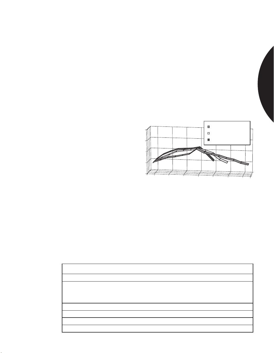
Amplitude
Frequency
, the
Glass Breaking
Pots & Pans Clanging
Doors Slamming
Pattern Recognition Technology™ is designed to eliminate
common false alarm sources and improve detection by
processing the pattern and timing relationships at points
across the entire frequency spectrum.
GLASSBREAK SENSORS
Choose the ShatterPro that’s right for you
Model Range Auto test End-user PRT* Occupied area 24-hour application/
ShatterPro II
5810A 25’ • • • •
5820A 25’ • • • •
5825 25’ • • • •
5845 Wireless 25’ • • • •
ShatterPro I
5800 Series 18’ • •
ShatterPro Plus
5885 Series 12’-15’ • • • • •
*Pattern Recognition Technology
to window verification perimeter loop Built in PIR sensor
1.2
Page 3
.........................................................................................................................................................................
Phone: 800.894.0412 - Fax: 888.723.4773 - Web: www.clrwtr.com - Email: [email protected]
Introduction
GLASSBREAK SHOCK SENSORS
Millions of Sentrol shock sensors installed around the world give testimony to our
product reliability. We’ve added some new products to give you more choices at
installation time and more ways to increase your sales.
Reliable, flexible shock sensors.
Breaking glass produces specific shock frequencies which travel through glass and
window frames. When shock sensors “feel” the wave generated by breaking glass,
they signal an alarm. These sensors mount directly on the glass or the frame and
give you a product virtually immune to false alarms. That means they can operate
on windows with heavy drapes or shutters. Shock sensors also provide a visual
deterrent to intruders helping to prevent break-in attempts.
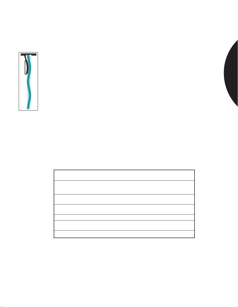
Most of Sentrol’s shock sensors are solid-state, with no mechanical parts to wear
out or fail. We incorporate a piezo transducer specifically tuned to the shock
Sentrol shock
sensors use a piezo
transducer
specifically tuned to
the shock frequency
of glass breaking.
frequency of glass breaking, providing both excellent detection and false alarm
immunity.
Choose the right sensor.
To choose the right shock sensor for a particular application or environment,
see the product comparison chart below.
Choose the Shock Sensor that’s right for you.
GLASSBREAK SENSORS
Shock Sensors
Model Coverage Mounting Powered Indicating Reed
5115/20 7’ Glass Self No No
5125 10’ Glass Self Yes No
5135 20’ Glass Wired Yes No
5414 10’ Glass or Frame Self Yes No
5415A 10’ Glass or Frame Self Yes Yes
5425 10’ Glass or Frame Wired Yes No
5428 10’ Glass or Frame Wired Yes Yes
Specialty Shock Sensors
GS600 Varies Glass, Frame, Wired Yes Yes
5422 2’x4’x1’ Metal Enclosure Wired Yes No
Site LED Switch
Wall, or Roof
1.3
Page 4
.........................................................................................................................................................................
Phone: 800.894.0412 - Fax: 888.723.4773 - Web: www.clrwtr.com - Email: [email protected]
Residential & Commercial Applications
INSTALLING ACOUSTIC GLASSBREAK SENSORS
IN PRE-WIRE APPLICATIONS
APPLICATION
New construction applications offer the opportunity to pre-wire an acoustic
glassbreak sensor, creating an attractive, unobtrusive installation.
Sentrol’s ShatterPro II can be used in a pre-wire by using the single gang box kit
(5828) or the trim ring. The pre-wire trim ring is almost unnoticeable in pre-wire
installations. Its 2-1/2 in. (6.35 cm) diameter size is almost one third smaller than a
single gang box plate.
GLASSBREAK SENSORS
INSTALLATION
RECOMMENDED
PRODUCTS
USING THE TRIM RING
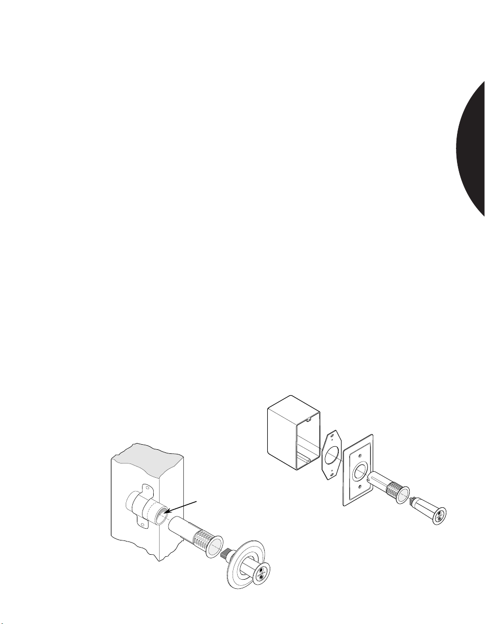
To pre-wire a Recessed ShatterPro, attach a 1 in. (2.54 cm) inside diameter pipe
about 2 1/2" (6.5 cm) long to a stud, in the desired location for the sensor, allowing
the pipe to protrude approximately 3/8 in. (.95 cm) beyond the stud. Run sensor
cable through the pipe. Don’t forget to leave enough slack to pull the wire out
later. (This shows the drywall installer that a security sensor is to be placed in this
location. The drywall installer will then cut a hole through the sheet rock for
the pipe.)
After the drywall is in place, the Recessed ShatterPro II can be inserted into
the pipe. After wiring, insert the 1 in. sleeve into the pipe, and the sensor into
the sleeve. Use the trim ring, if necessary, to cover any irregularities in the
drywall hole.
USING THE SINGLE GANG BOX KIT
This kit includes a plastic front plate, metal plate for alignment and painted
finishing screws.
The 5820A Recessed ShatterPro II acoustic glassbreak sensor, and the 5829 Trim
Ring and 5828 Single Gang Box Kit.
1" I. D. x 2 1/2" long
1.4
Page 5
.........................................................................................................................................................................
Phone: 800.894.0412 - Fax: 888.723.4773 - Web: www.clrwtr.com - Email: [email protected]
Residential & Commercial Applications
INSTALLING RECESSED GLASSBREAK SENSORS
WHEN APPEARANCE IS IMPORTANT
APPLICATION
INSTALLATION
RECOMMENDED
PRODUCTS
Some customers want their security system to be as inconspicuous as possible.
This is especially true in most residential installations, office entry foyers,
executive offices, and upscale retail stores.
Sentrol’s Recessed ShatterPro II and the Sentrol ShatterSwitch are the least
obtrusive acoustic glass break sensors available.
The Recessed ShatterPro II acoustic sensor recess mounts in a 1 in. (2.54 cm) hole.
See installation instructions on previous page for pre-wired installations.
When installing the Recessed ShatterPro II in existing residences and commercial
facilities, drill a 1 in. hole through the drywall or ceiling tile, in the desired
location. Insert the 1 in. sleeve into the hole, and the sensor into the sleeve. Use
the trim ring, if necessary, to cover any irregularities in the drywall hole. (A hole
saw makes the neatest hole, but a spade bit with cutting tips will usually work also.
A twist drill should be avoided because it tends to tear the sheet rock covering.)
One sensor can protect an entire room. Sensor range is 25 ft. (7.62 m) to the
bottom of the glass in a 360˚ pattern, so the sensor can be ceiling mounted,
mounted on the opposite wall, or on an adjoining wall. When installed, the
Recessed ShatterPro II is little larger than a quarter, and is therefore rarely noticed.
The Sentrol ShatterSwitch is a shorter range sensor which protects up to 10 ft.
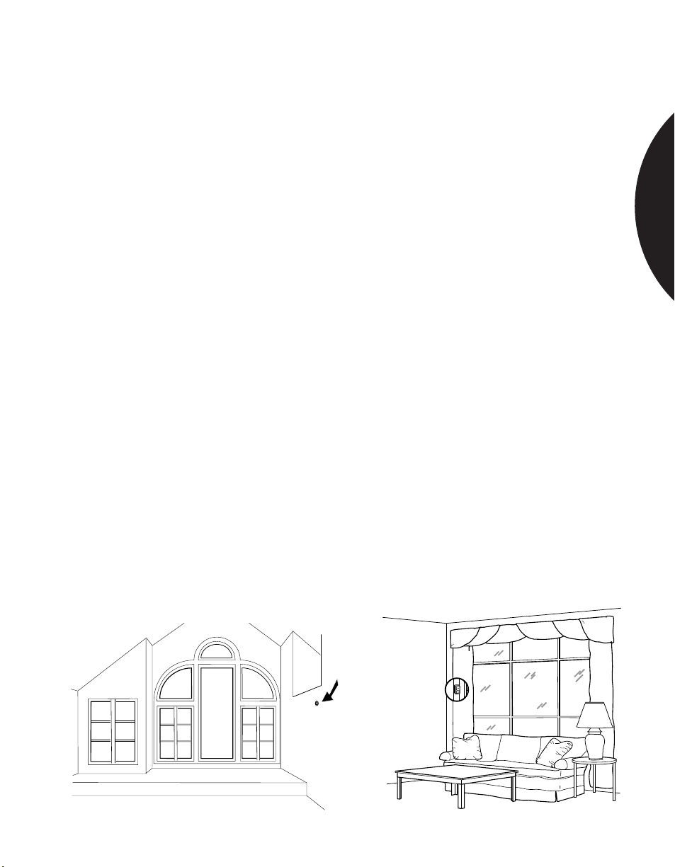
(3.05 m) of glass. For a hidden appearance, mount the ShatterSwitch on the
window frame behind curtains or blinds.
For protecting a large glass area, use a 5820A Recessed ShatterPro II. For smaller
areas of glass, a ShatterSwitch 5725T can be used. A ShatterSwitch 5728T with
built in reed switch will also detect the opening of the door or window. An optional
90˚ mounting bracket, part number 5702, may be helpful when mounting the
ShatterSwitch on a narrow window frame.
GLASSBREAK SENSORS
S
E
N
T
R
O
L
1.5
Page 6
.........................................................................................................................................................................
Phone: 800.894.0412 - Fax: 888.723.4773 - Web: www.clrwtr.com - Email: [email protected]
Residential & Commercial Applications
PROTECTING BATHROOM WINDOWS
GLASSBREAK SENSORS
APPLICATION
INSTALLATION
RECOMMENDED
PRODUCTS
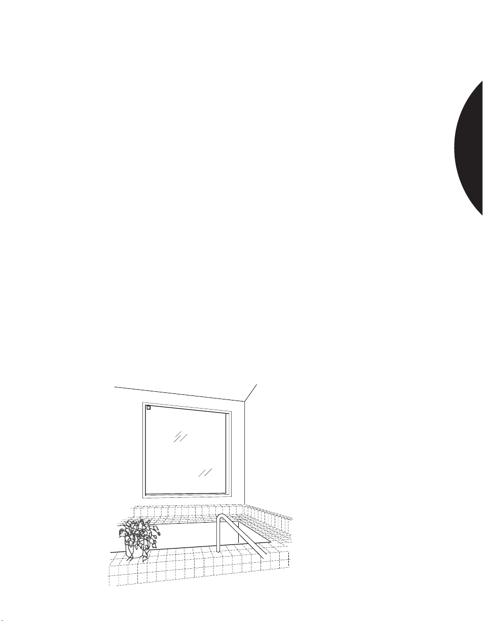
In residential installations, bathroom windows may have to be protected as part of
a complete perimeter system. Bathrooms are challenging environments for glass
break sensors for two reasons. 1) Humidity can be very high when a shower or tub
is used. 2) Bathrooms are acoustically live rooms — they are typically small, with
bare floors and many sound-reflecting surfaces. Acoustically live rooms have a
greater potential for false alarms when acoustic glassbreak sensors are used.
Humidity can also be a problem for most glassbreak sensors. Sentrol offers a
hermetically sealed shock sensor, the GS610, that works with a separate analyser,
the GS614. Shock sensors have fewer problems than acoustic sensors in high
humidity environments.
Since shock sensors are not “listening,” they are the preferred choice for
acoustically live rooms, such as bathrooms. For best false alarm immunity in
bathrooms, if possible use a hermetically sealed shock sensor mounted on the glass
or a frame mounted shock sensor.
If an acoustic sensor is to be used, select a sensor with range comparable to the
size of the room. In a 10 ft. (3.05 m) bathroom, for example, it is better to use a
sensor with a 10 ft. range than a 25 ft. (7.5 m) range. The 25 ft. sensor is too “hot”
for such a small, acoustically-live room, and would be vulnerable to false alarms.
The GS610 shock sensor, with 12 ft. (4 m) of range, provides excellent false alarm
immunity and humidity tolerance. The GS611 frame mounted shock sensor with
built-in reed switch can protect windows that open. Both sensors work in
conjunction with the GS614 analyser.
The 5810A-W4 reduced sensitivity ShatterPro™ II with advanced Pattern
Recognition Technology™ can also be used in some bathroom applications.
1.6
Page 7
.........................................................................................................................................................................
Phone: 800.894.0412 - Fax: 888.723.4773 - Web: www.clrwtr.com - Email: [email protected]
Residential & Commercial Applications
PROTECTING SKYLIGHTS
GLASSBREAK SENSORS
APPLICATION
INSTALLATION
RECOMMENDED
PRODUCTS
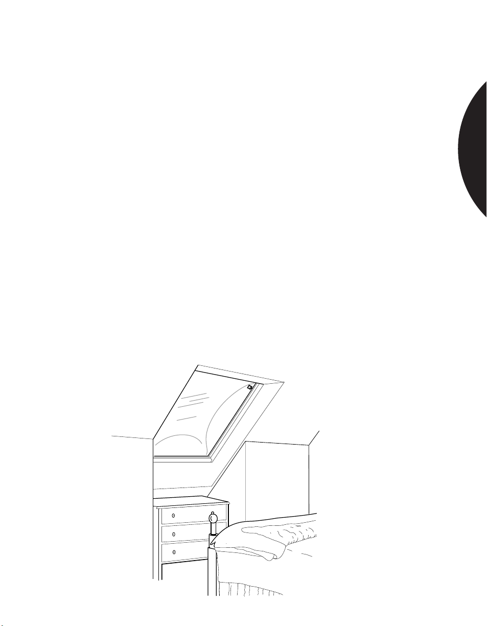
Skylights can be a vulnerable entry point to many homes and businesses. Many
skylights are made of Plexiglas™, Lexan™, or other type of plastic. This
eliminates the option of using acoustic glassbreak sensors since they are designed
for detecting breaking glass, not plastic.
For protecting plastic skylights, mount a shock sensor in a corner of the skylight
1 in. (2.54 cm) from the frame.
Note: The plastic material in the skylight will absorb much of the shock energy
from a break. The range of a shock sensor on plastic is typically 50% less than the
range on glass. A shock sensor with a 7 ft. (2.13 m) range on glass would generally
have a 3-1/2 ft. (1.07 m) range on a plastic skylight.
When protecting plastic skylights, it is essential to thoroughly test the sensor by
rapping the far opposite corner of the skylight with the handle of an 8"-10"
screwdriver. If the sensor trips to the rap test, its range is sufficient to detect an
actual break-in.
An acoustic glassbreak sensor can be used for glass skylights. The sensor can be
mounted on any wall within range of the skylights, or on the ceiling.
Use a Sentrol 5115/20 shock sensor for plastic skylights if 3-1/2 ft. (1.07 m) of
range is sufficient, or use two sensors mounted in opposite corners if additional
range is required.
For glass skylights, another option is a 5725T ShatterSwitch, if it can be mounted
within range.
1.7
Page 8
.........................................................................................................................................................................
Phone: 800.894.0412 - Fax: 888.723.4773 - Web: www.clrwtr.com - Email: [email protected]
Residential & Commercial Applications
PROTECTING ROOMS WITH
CURTAINS AND BLINDS
APPLICATION
INSTALLATION
RECOMMENDED
PRODUCTS
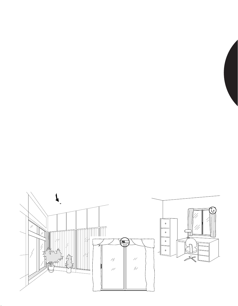
Many homes and offices have curtains or blinds on at least some of the windows.
Sentrol shock sensors provide glass break detection regardless of the type of
window coverings present. With proper placement, Sentrol’s acoustic sensors may
also be used when blinds and light drapes are present.
Glass mounted or frame mounted shock sensors are unaffected by curtains and
blinds. The sensor should be mounted in the corner of the glass, 1 in. (2.54 cm)
from the frame.
Sentrol’s acoustic ShatterSwitch mounts behind curtains or blinds, and can protect
multiple windows. Mount the ShatterSwitch on the window frame to protect one
or more windows. It will protect a 10 ft (3.05 m) area. However, its range can be
reduced if window coverings are touching the glass.
Sentrol’s acoustic ShatterPro II can be mounted anywhere in a room except on the
frame (as long as the glass to be protected is within its range), and can detect
breaking glass when blinds and light drapes are present. Mount the ShatterPro II
on the ceiling, on an adjoining wall, or on a wall opposite from the glass to be
protected. Mounting the ShatterPro on the same wall as the glass should be
avoided because the signal may be dampened before it bounces back to
the sensor.
Test the range with the 5709C tester held behind the closed curtains or drapes. If
the sensor does not trip, it will be necessary to relocate the sensor closer to the
protected glass, or use additional sensors.
For shock sensor protection, use a 5115/20 or a 5425 shock sensor. For acoustic
glassbreak detection, use a ShatterSwitch 5725T. Or, use a 5728T ShatterSwitch
with built-in reed switch to also detect forced opening of the door or window. For a
larger range, use the ShatterPro II 5810A or the Recessed ShatterPro II 5820A.
GLASSBREAK SENSORS
1.8
Page 9
.........................................................................................................................................................................
Phone: 800.894.0412 - Fax: 888.723.4773 - Web: www.clrwtr.com - Email: [email protected]
Residential & Commercial Applications
PROTECTING LARGE ROOMS WITH
MULTIPLE WINDOWS
APPLICATION
INSTALLATION
RECOMMENDED
PRODUCTS
Most large rooms have several windows, often widely spaced from each other.
The most economical way to protect large rooms with multiple windows is with a
single, long range acoustic sensor. However, care should still be taken to match
sensor range to room size. A sensor whose range extends well beyond the
boundaries of the room is acoustically “hot” and vulnerable to false alarms.
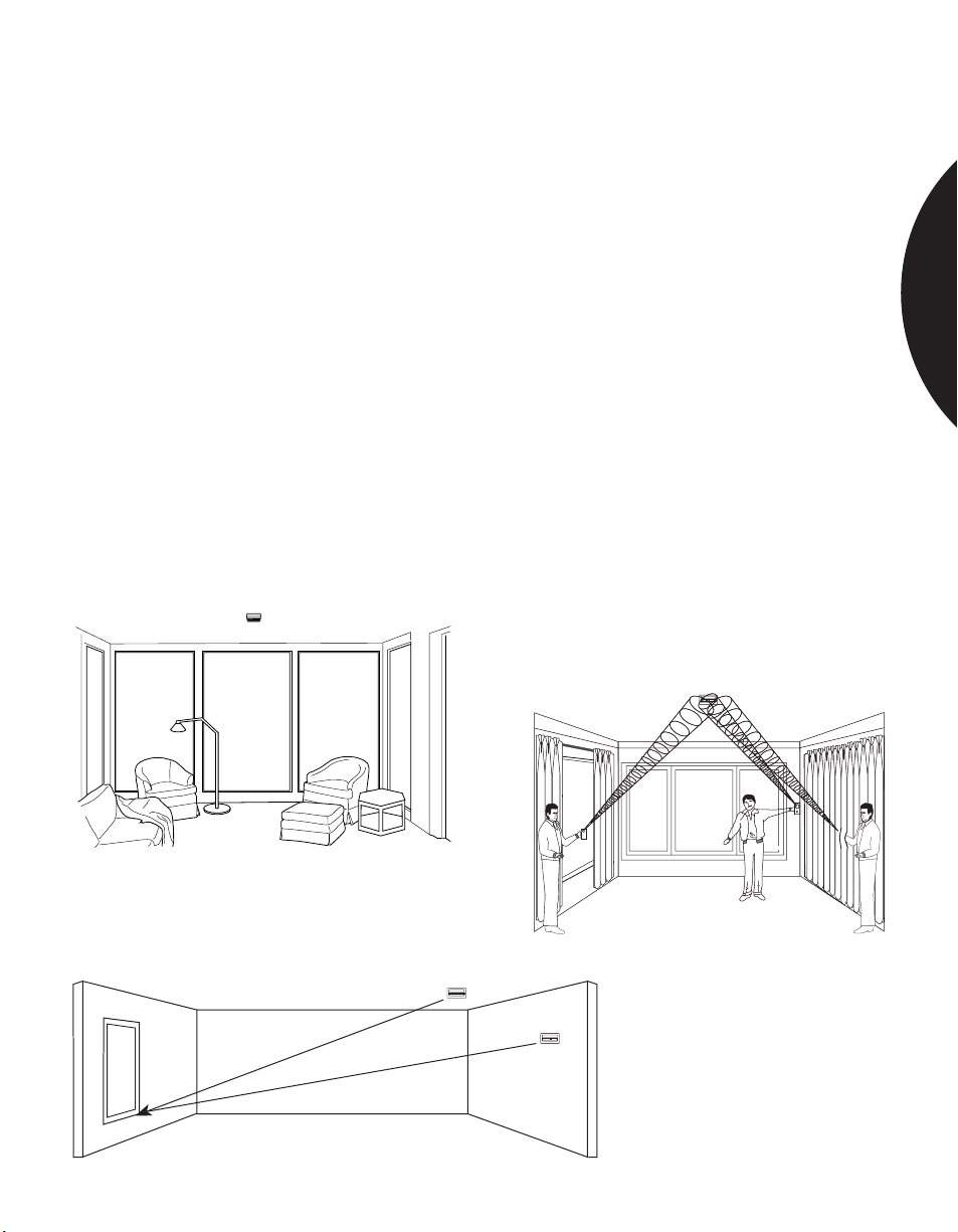
For protecting glass on more than one wall, ceiling mounting is most desirable.
Make sure that all protected glass is within the radius coverage of the sensor. For
any glass to be protected by an acoustic sensor, the distance from the bottom of
the window to the sensor must be no more than the sensor’s maximum range.
For protecting one wall of glass, mounting an acoustic sensor on the opposite wall
is best (if all the glass to be protected is within the sensor’s range).
Always confirm range with a Sentrol 5709C hand-held tester.
For glass areas less than 10 ft. (3.05 m) or behind heavy curtains use a Sentrol
5725T ShatterSwitch mounted on the frame. For protecting large glass areas, a
single 5810A ShatterPro II, with its 25 ft. (7.6 m) range, can protect up to four walls
of glass. The 5820A Recessed ShatterPro II mounts in a 1 in. (2.54 cm) hole in the
ceiling, opposite wall or adjacent walls.
GLASSBREAK SENSORS
, Temp wired, Lam
25' (7.5 m) Plate
25' (7.5m) Plate, Temp wired, Lam
1.9
Page 10
.........................................................................................................................................................................
Phone: 800.894.0412 - Fax: 888.723.4773 - Web: www.clrwtr.com - Email: [email protected]
Residential & Commercial Applications
PROTECTING SMALL ROOMS WITH GLASS
GLASSBREAK SENSORS
APPLICATION
INSTALLATION
RECOMMENDED
PRODUCTS
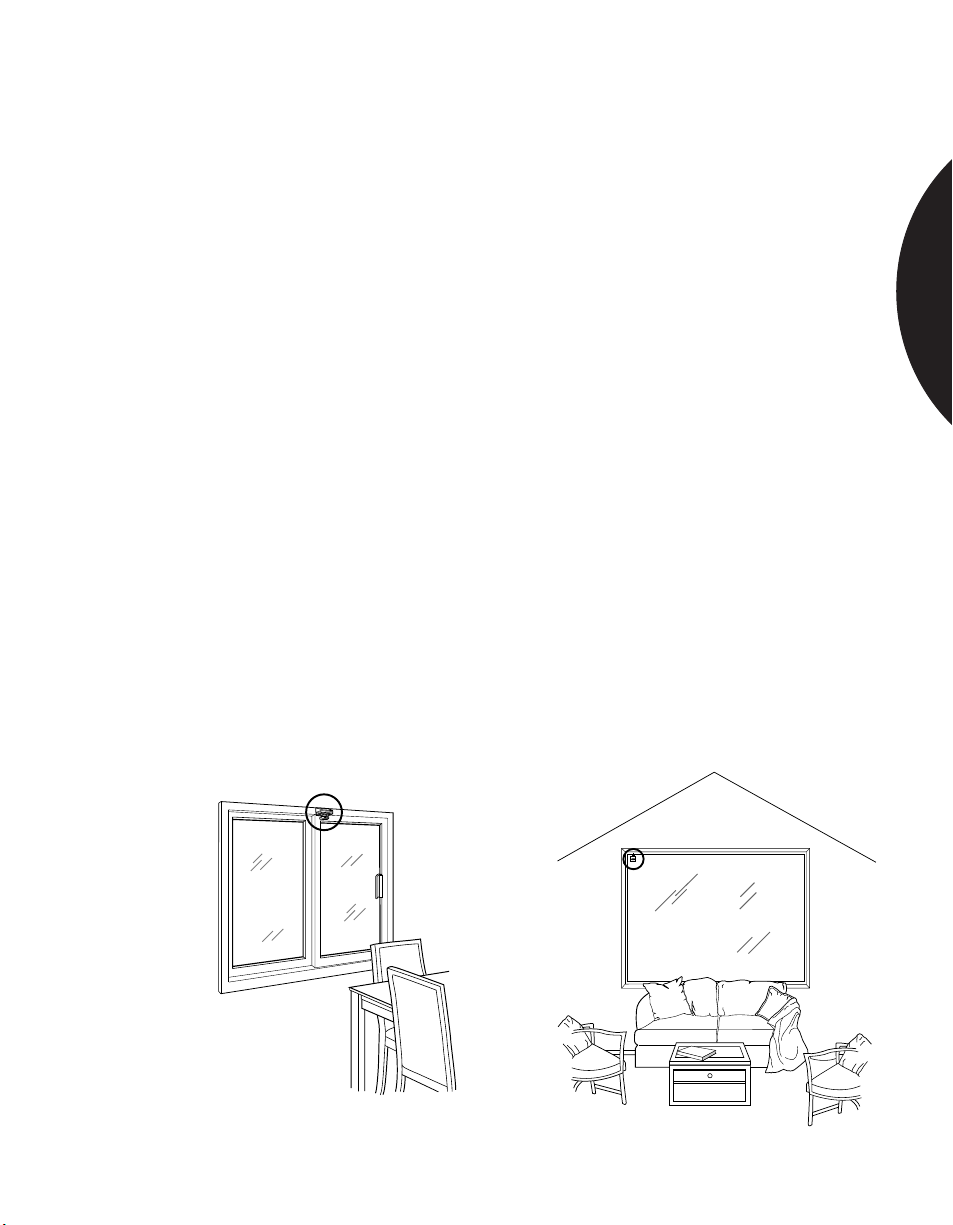
False alarms are more likely in small, acoustically live rooms such as small
kitchens, glass entry airlocks, stairwells, small glass offices, and utility rooms. For
best false alarm immunity the range of the sensor should be matched to the size of
the room and glass area to be protected.
Shock sensors offer the best false alarm immunity in acoustically live rooms, and
are the most economical if there is only one window to protect. Acoustic sensors
will provide good false alarm immunity if selected properly.
If it can be avoided, do not install acoustic sensors with large range into small
rooms. A sensor with 25 ft. (7.5 m) diameter range into a 10 ft. (3.05 m) room
increases the risk of false alarm. Choose an acoustic sensor with range comparable
to the size of glass to be protected.
In a small room with just one window, the Sentrol 5115/20 shock sensor provides
economical protection and false alarm free operation in virtually all acoustically
live applications. The 5414 or 5415A frame mount shock sensors are also a good
choice. The 5415A has a built-in reed switch to protect windows that open.
For multiple windows the 5725T (ShatterSwitch) or the 5810A-W4 reduced
sensitivity (ShatterPro II) can be considered for small rooms.
Verify correct sensor placement with the Sentrol 5709C hand-held tester.
To protect just one window, use the 5115/20 shock sensor. For protecting multiple
windows in a small room, use a 5810A-W4 reduced sensitivity ShatterPro II or
multiple shock sensors. The 5415A or 5426 frame mount shock sensors with builtin reed switches can be used to protect windows that open.
L
O
R
T
N
E
S
L
O
R
T
N
E
S
1.10
Page 11
.........................................................................................................................................................................
Phone: 800.894.0412 - Fax: 888.723.4773 - Web: www.clrwtr.com - Email: [email protected]
Residential & Commercial Applications
PROTECTING OCCUPIED AREAS
GLASSBREAK SENSORS
APPLICATION
INSTALLATION
RECOMMENDED
PRODUCTS
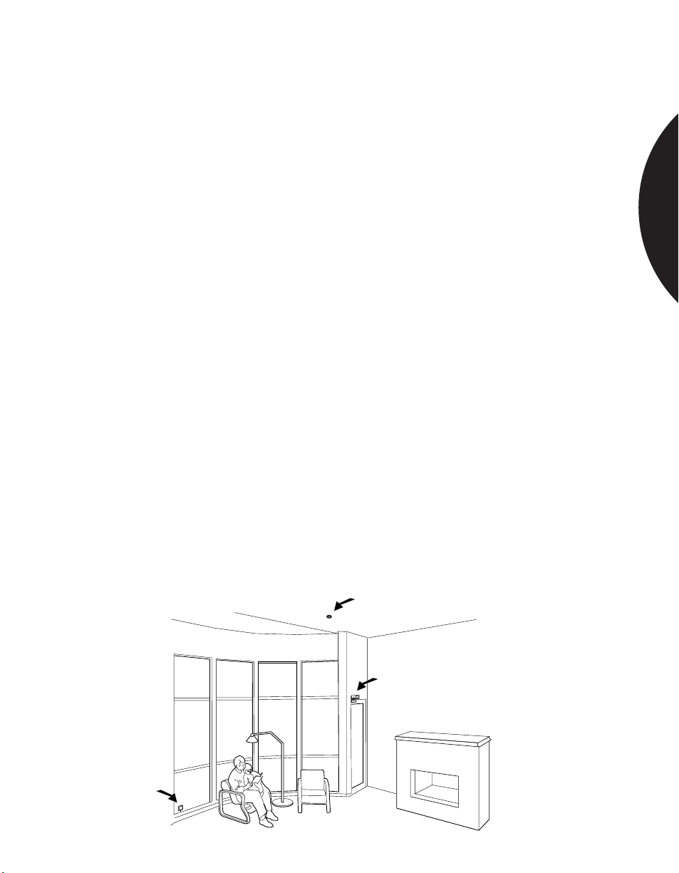
Glassbreak sensors can be armed while rooms are occupied to alert the family
inside a home or the employee working late or on the weekend.
Occupied area protection means sensors are armed when the perimeter loop of the
system is armed. In contrast to 24-hour loops, which are armed continuously, all
day and all night, a perimeter loop containing glassbreak sensors is armed only
when the magnetic contacts on doors are armed — generally, after hours, when
buildings are quieter.
Today’s advanced acoustic sensors provide excellent false alarm immunity in
occupied areas if installed on the perimeter loop. Sentrol shock sensors and the
ShatterPro™ Plus 5885 provide 24-hour loop protection without false alarms.
For 24-hour loop protection, mount Sentrol’s 5115/20 shock sensors on the glass to
be protected, 1 in. (2.54 cm) from the corner.
Frame mounted shock sensors such as the 5425 will also provide 24 hour loop
protection without false alarms if sensitivity is set properly. Sentrol also offers a
motion sensitive acoustic glassbreak product, the 5885, for use in 24 hour
applications (see page 24).
For perimeter protection using acoustic sensors, use a ShatterSwitch for protecting
glass areas smaller than 10 ft. (3.05 m). Use Sentrol’s advanced ShatterPro II to
protect large glass areas on the perimeter loop.
To test shock sensors, rap the protected glass with the handle of a screwdriver in
the corner farthest from the sensor. This should trip the sensor. Verify range
coverage of acoustic sensors with the Sentrol 5709C hand-held tester.
For shock sensor protection, the 5115/20 provides the best false alarm immunity
with the 5425 also a good solution. The ShatterSwitch 5725T, the ShatterPro II
5810A, and the Recessed ShatterPro II 5820A provide excellent false alarm
immunity in occupied areas on the perimeter loop. The ShatterPro Plus 5885 is
also recommended for 24 hour acoustic glassbreak coverage.
1.11
Page 12
.........................................................................................................................................................................
Phone: 800.894.0412 - Fax: 888.723.4773 - Web: www.clrwtr.com - Email: [email protected]
Residential & Commercial Applications
PROTECTING A SINGLE WINDOW WITH
WIRELESS COMPATIBLE SENSORS
APPLICATION
INSTALLATION
RECOMMENDED
PRODUCTS
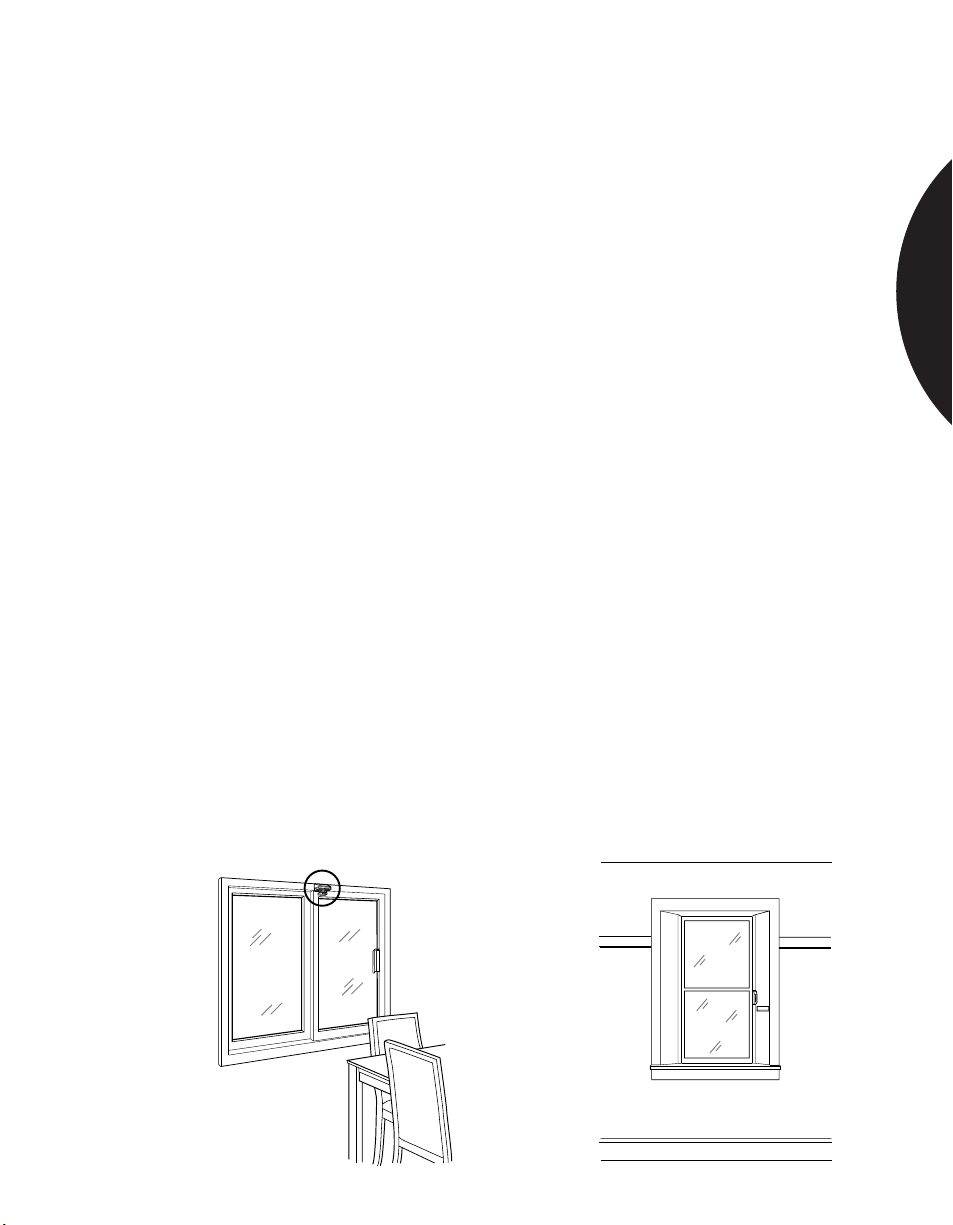
A wireless compatible shock sensor can be used for economical protection of rooms
with a single window. For glass doors or windows which open, use a wireless
compatible sensor with a built-in reed switch.
Sentrol’s 5115/20 wireless compatible shock sensor is a two-wire device which
draws no power, and therefore has no impact on the transmitter’s battery life.
Mount the 5115/20 on the glass, 1 in. (2.54 cm) from the corner. Range is 7 ft.
(2.13 m) radius out from the sensor.
The 5414 or 5415A frame mounted shock sensor can protect two fixed windows in
the same window opening. An internal lithium battery powers the sensor for up to
15 years, so there is no draw on the transmitter battery. Range for the 5414 or
5415A is up to 10 ft. (3.05 m). Frame mounting affects sensor range, so it is
essential to test the sensor by rapping the glass on the side opposite the sensor.
The sensor must trip to the rap test to ensure proper operation. The 5415A
includes a built-in reed switch and a magnet to protect against opening the
window.
For protecting glass doors or windows that open, mount a Wireless ShatterSwitch
acoustic sensor within the window bay. The ShatterSwitch will protect a 10 ft.
(3.05 m) area of glass. Test the sensor’s range using the Sentrol 5709C hand-held
tester.
Note: The Wireless ShatterSwitch shares the battery of the transmitter. Its current
draw of up to 15 micro amps may reduce transmitter battery life by up to 50%.
Since other devices are likely to need battery replacement before the
ShatterSwitch, this is rarely a problem.
Use the Sentrol self-powered 5115/20 for glass-mounted applications, or the
lithium battery powered 5414 shock sensor for frame mounting. Use the 5415A
shock sensor with built-in reed switch to protect windows that open.
For acoustic sensor protection use the Wireless ShatterSwitch 5741. Use the 5742
Wireless ShatterSwitch with built-in reed switch to protect glass doors and
windows that open.
GLASSBREAK SENSORS
L
O
R
T
N
E
S
L
O
R
T
N
E
S
1.12
Page 13
.........................................................................................................................................................................
Phone: 800.894.0412 - Fax: 888.723.4773 - Web: www.clrwtr.com - Email: [email protected]
Residential & Commercial Applications
PROTECTING MULTIPLE WINDOWS WITH
WIRELESS COMPATIBLE SENSORS
APPLICATION
INSTALLATION
RECOMMENDED
PRODUCTS
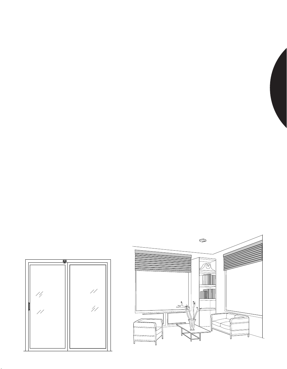
In many installations it is desirable to protect rooms with several windows. This
can be accomplished economically using one transmitter and a wireless compatible
acoustic sensor.
Sentrol’s Wireless ShatterPro acoustic glassbreak sensor combines excellent false
alarm immunity and consistent detection with wireless compatibility. The Wireless
ShatterPro has a coverage radius of 20 ft. (6.1 m), [40 ft. (12.2 m) diameter] if
ceiling mounted. A single sensor, therefore, can typically protect an entire room.
Mount the transmitter inside the back box of the Wireless ShatterPro 5845, which
hides the transmitter and provides an integrated look. If desired, the transmitter
can also be mounted next the sensor module on the bracket included.
Note: The sensor shares the transmitter battery, which may reduce battery life by
up to 50%. Since other devices are likely to need battery replacement before the
Wireless ShatterPro, this is rarely a problem.
Position the Wireless ShatterPro anywhere in the room except within the frame.
The best location for detection is directly opposite the glass. Since wireless sensor
placement is not determined by wire routing, opposite wall mounting is a more
practical option than with hard wire installations.
Verify sensor range and placement with the 5709C hand-held tester.
For glass areas smaller than 10 sq. ft. (3 sq. m) use the Sentrol’s Wireless
ShatterSwitch 5741. For forced open protection as well, use the 5742 with built-in
reed switch. For glass areas larger than 10 sq. ft., or for an integrated appearance,
use the Wireless ShatterPro 5845.
GLASSBREAK SENSORS
1.13
Page 14
.........................................................................................................................................................................
Phone: 800.894.0412 - Fax: 888.723.4773 - Web: www.clrwtr.com - Email: [email protected]
Residential & Commercial Applications
PROTECTING SMALL WINDOWS,
FRENCH DOOR GLASS, FRENCH WINDOWS
APPLICATION
INSTALLATION
RECOMMENDED
PRODUCTS
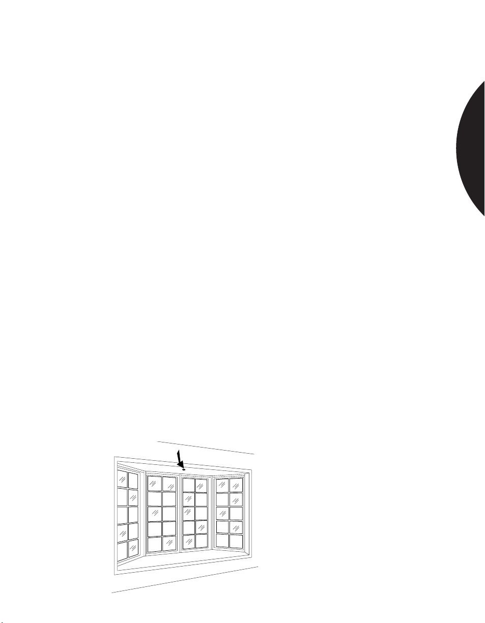
Small French door type windows are common in older homes. The glass panels are
typically 6 in. x 9 in. (15.2 cm x 22.9 cm) or larger. Small windows have unique
properties when they break. First, the sound output may be low since there is not
much glass to break. Second, the glass may just pop out of the frame when hit,
rather than breaking. This is particularly true of glass in old wooden frames.
Detection in both cases can be difficult.
Modern French-type windows are usually two large panes of glass with false
dividers between them. The dividers have little effect from a detection
standpoint. Detection of false French windows is the same as with standard size
windows, and no special precautions need to be taken.
The 5725T ShatterSwitch provides good protection of small windows if installed
within 4 ft. of the glass to be protected. Most acoustic sensors are only rated down
to a minimum glass size of 1 ft. x 1 ft. (30.5 cm x 30.5 cm) or larger. If protecting a
smaller window than the sensor’s minimum rated size, the capture rate will
decrease by as much as 50%. The customer should be informed that sensor detection has
been compromised. With small windows, it is best to locate the acoustic sensor close
to the protected glass.
More consistent detection can be achieved using a frame mounted shock sensor.
Often several sensors will be needed to protect a frame of several windows. Take
particular care to thoroughly test sensor range by rapping on the windows farthest
from the sensor. The sensor must trip to the rap test. Use additional sensors on
each side of the glass until a rap to any pane of glass will trip at least one shock
sensor.
For acoustic protection of smaller windows, use a ShatterPro II 5810A or 5820A.
The ShatterPro™ II is not recommended for windows smaller than 1 ft. x 1 ft.
(30.5 cm x 30.5 cm). The 5725T ShatterSwitch can be used if mounted within 4 ft.
of the protected glass.
The 5425 shock sensor can be mounted on the frame to protect multiple panes of
small glass. Several sensors may be required.
GLASSBREAK SENSORS
1.14
Page 15
.........................................................................................................................................................................
Phone: 800.894.0412 - Fax: 888.723.4773 - Web: www.clrwtr.com - Email: [email protected]
Residential & Commercial Applications
PROTECTING GLASS DOORS AND
WINDOWS THAT OPEN
APPLICATION
INSTALLATION
RECOMMENDED
PRODUCTS
Protecting glass doors and windows that open can be a challenge because of the
difficulty of running wires from the glass to the frame. Glassbreak and forced-open
protection can, however, be achieved with a single detector.
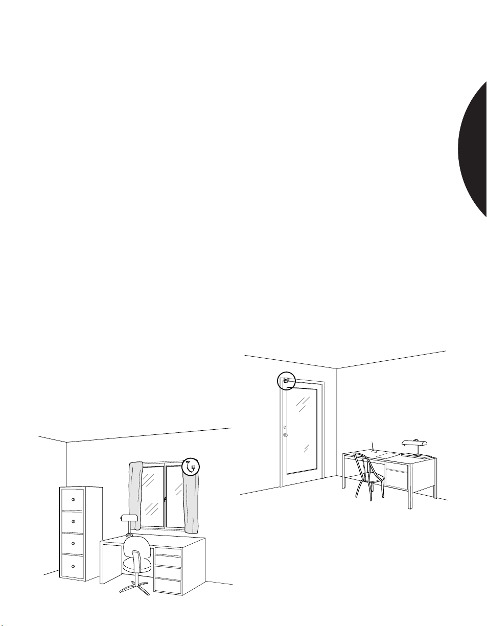
For shock sensor protection, both on-the-glass and frame-mounted sensors can be
used. The 5120C shock sensor ships with 3 ft. (.91 m) of coil cord. The sensor
mounts in a corner on the glass, and the coil cord reaches to a termination on the
frame. As the window or door opens, the coil cord stretches as needed.
Frame-mounted shock sensor models are available which also have a built-in reed
switch with magnet. These sensors provide both glass break detection as well as
forced open detection. Mount the sensor’s magnet on the door or moveable
window, and mount the sensor on the frame as close as possible to the magnet.
For acoustic sensor protection use a Sentrol ShatterSwitch with built-in reed
switch and magnet. This provides coverage of 10 ft. (3.05 m) of glass, including
multiple windows, while detecting forced opening as well. The ShatterSwitch
should be centered at the top of the glass, or as near to center as practical for
magnet location.
Use a 5120C shock sensor with coil cord for on-the-glass protection. The 5426
frame-mount shock sensor with built-in reed switch provides double protection.
The ShatterSwitch is available in standard configuration, part number 5725T, and
also with built-in reed switch, part number 5728T. A 90˚ mounting bracket, part
number 5702, is useful on narrow frames.
GLASSBREAK SENSORS
S
E
N
T
R
O
L
1.15
Page 16
.........................................................................................................................................................................
Phone: 800.894.0412 - Fax: 888.723.4773 - Web: www.clrwtr.com - Email: [email protected]
Residential & Commercial Applications
PROTECTING INSULATED GLASS
GLASSBREAK SENSORS
APPLICATION
INSTALLATION
RECOMMENDED
PRODUCTS
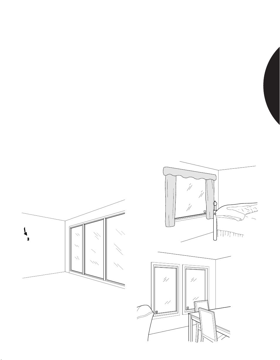
Many modern buildings use windows that contain two panes of glass divided by an
air space for added insulation. This insulated glass can be protected by shock and
acoustic glassbreak sensors. As long as the inside pane of glass breaks, the sensor
will detect the break. It is possible to break the outside pane of glass without
setting off an alarm.
Installation for thermopane windows is the same as for other windows. Shock
sensors should be mounted in the corner or frame mounted. Acoustic sensors
should be mounted so that the protected glass is within range.
Rap test the shock sensors. Test acoustic sensors with the Sentrol 5709C handheld tester.
Use a 5115/20 shock sensor for on-the-glass protection. The 5426 frame-mount
shock sensor with built-in reed switch provides double protection for windows
which open.
Use the 5725T ShatterSwitch, 5728T with built-in reed switch, or 5810A
ShatterPro II for acoustic protection.
1.16
Page 17
.........................................................................................................................................................................
Phone: 800.894.0412 - Fax: 888.723.4773 - Web: www.clrwtr.com - Email: [email protected]
Commercial Applications
PROTECTING STOREFRONT GLASS
GLASSBREAK SENSORS
APPLICATION
INSTALLATION
RECOMMENDED
PRODUCTS
Merchants often want glass break protection on their front windows, in order to
have the alarm sound as soon as the glass breaks. While this does not prevent
“smash and grab” losses, it will prevent most burglars from actually entering
the building.
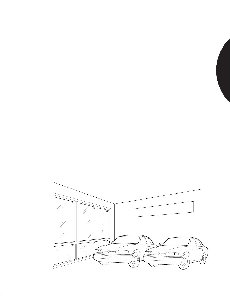
For storefront windows shock sensors are always the best choice. A shock sensor is
visible from the outside, which might deter burglars before the glass is broken.
And shock sensors are less likely to be set off by street noise, or by rolling metal
shutters, than are acoustic sensors. Due to range limitations, however, shock
sensors can be more expensive to install. Multiple sensors may be required to
cover the same glass area that one acoustic sensor can protect.
Acoustic sensors can be successfully used to protect storefront glass if store
personnel are properly trained to not block the glass. Acoustic sensors must be able
to “see” all the glass that they are protecting. If a sensor’s line of sight to the glass
is blocked by store displays or furniture, the sensor is unlikely to detect a break-in
through the blocked glass.
If selecting an acoustic sensor, in stores which do not have window displays, mount
a ShatterPro in the ceiling inside the room. For stores with window displays,
mount a ShatterSwitch directly above the glass.
Use the 5115/20 for on-the-glass shock sensor protection, or use the 5425 for
frame mounting.
For acoustic sensor protection, use a ShatterPro II 5810A, a Recessed ShatterPro
5820A, or a ShatterSwitch 5725T.
New Models Are Here
1.17
Page 18
.........................................................................................................................................................................
Phone: 800.894.0412 - Fax: 888.723.4773 - Web: www.clrwtr.com - Email: [email protected]
Commercial Applications
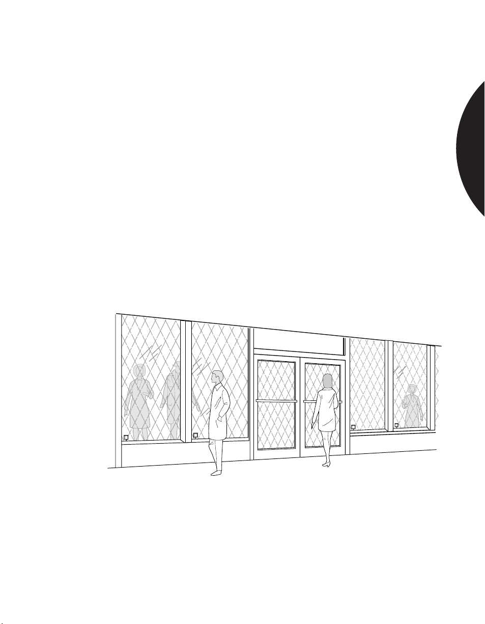
PROTECTING STORE WINDOWS
WITH ROLL-UP METAL SHUTTERS
APPLICATION
INSTALLATION
RECOMMENDED
PRODUCTS
Retail shops in high crime areas will often have roll-up metal shutters to protect
the glass windows at night. The clanging and banging sounds of these shutters can
cause acoustic sensors to false alarm. False alarms can also be caused by people
rattling the shutters, and by other vibrations.
For windows with roll-up shutters, shock sensors provide the best false alarm
immunity. On-the-glass shock sensors have better false alarm immunity than
frame-mounted shock sensors, and are therefore the preferred choice. On-the-glass
sensors are also easily visible from the outside, which may help deter a break-in.
If using acoustic sensors, use only an advanced sensor with excellent false alarm
immunity. Mount the sensor back into the room, away from street and roll-up
shutter sounds. An advanced sensor mounted 15 ft. back from the glass should
provide false-alarm-free operation in most applications.
Use the 5115/20 for on-the-glass shock sensor protection, or use the 5425 for
frame mounting.
Use a ShatterPro II 5810A, or a Recessed ShatterPro II 5820A, for acoustic
sensor protection.
GLASSBREAK SENSORS
1.18
Page 19
.........................................................................................................................................................................
Phone: 800.894.0412 - Fax: 888.723.4773 - Web: www.clrwtr.com - Email: [email protected]
Commercial Applications
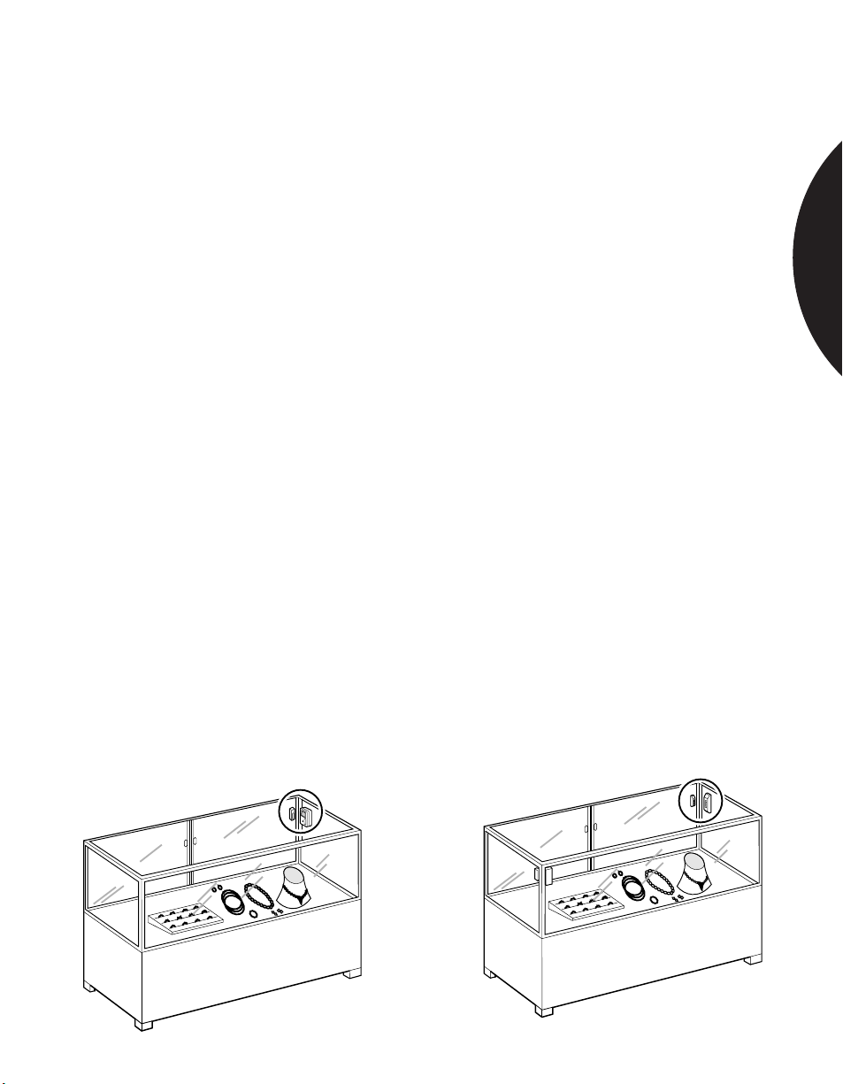
PROTECTING DISPLAY AND JEWELRY CASES
GLASSBREAK SENSORS
APPLICATION
INSTALLATION
RECOMMENDED
PRODUCTS
Museum curators and retailers with glass display and jewelry cases often want the
extra protection of glassbreak sensors inside their cases. Both shock sensors and
acoustic sensors are options for such protection.
Note: Acoustic glassbreak sensors sealed within a glass box are extremely “live,”
and are vulnerable to false alarms if the case is accidentally struck by keys or other
metal objects. For this reason, acoustic sensors are appropriate only if the sensor
will be armed while the premises are not occupied.
For occupied or 24-hour protection of display cases, it is best to use shock sensors.
A frame mounted shock sensor will provide the most economical protection if
there is more than one piece of glass to protect. To prevent sensor tampering, the
glassbreak sensors must be placed inside the case.
Test the installation by rapping the protected glass farthest away from the sensors.
If the shock sensor does not trip to this rap test, it may not trip to an actual break.
Add additional sensors until at least one sensor trips on each rap test.
Note: An actual glass break generates twice as much energy to the shock sensor as
a rap test.
More than one shock sensor may be needed to protect all the glass in a display
case. If, for cosmetic reasons, this is not a viable solution, a single acoustic sensor
may be used. To protect a glass case when a room is not occupied, use an acoustic
sensor with limited range, such as the Sentrol ShatterSwitch , with its 10 ft.
(3.05 m) range. The ShatterPro II is not recommended for display cases because it
is not designed to detect the prying of the case tops.
For acoustic sensor protection, the ShatterSwitch 5725T by Sentrol will generally
protect an entire case. A 5728T with built-in reed switch can be used to detect
forced opening of the access door.
The 5115/20 shock sensor mounts directly onto the glass, and is the best choice if
only one piece of glass is to be protected. For protecting multiple glass walls in the
case, use one or more 5425 shock sensors. Use a 5426 with built-in reed switch to
detect the forced opening of the access door.
L
O
R
T
N
E
S
L
O
R
T
N
E
S
1.19
Page 20
.........................................................................................................................................................................
Phone: 800.894.0412 - Fax: 888.723.4773 - Web: www.clrwtr.com - Email: [email protected]
Commercial Applications
PROTECTING METAL ENCLOSURES
GLASSBREAK SENSORS
APPLICATION
INSTALLATION
RECOMMENDED
PRODUCTS
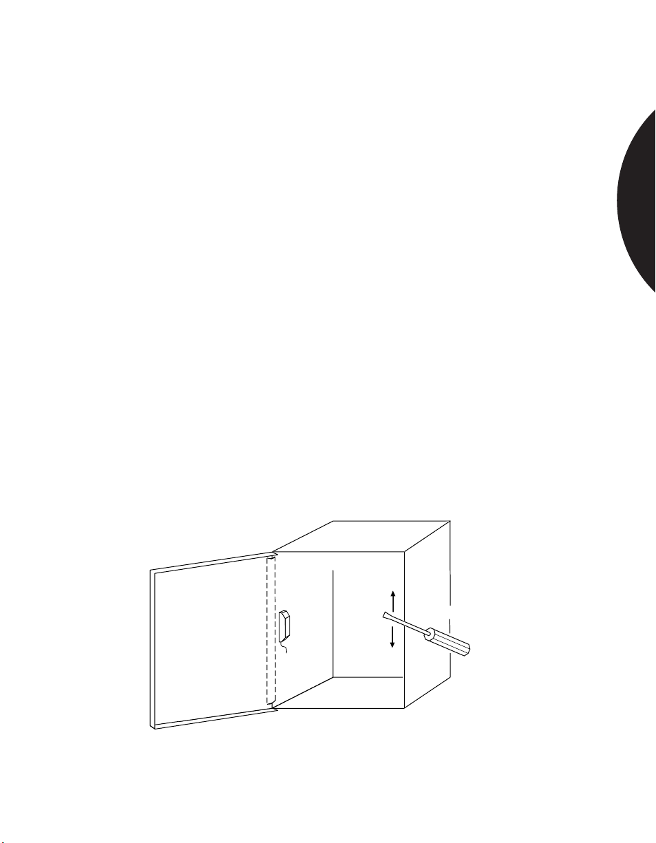
Sentrol’s 5402 shock sensor eliminates the need for costly lined boxes or
placement of security system controls in a vault for UL mercantile applications.
The sensor mounts inside the enclosure on the hinge side of the box for best
response.
Locate the sensor inside the enclosure on the side wall on or near the hinge. If the
hinge runs the length of the side, center the sensor vertically. If the enclosure has
multiple hinges, place the sensor next to the hinge nearest the middle of the
enclosure.
Peel back paper from one side of adhesive tape pad and press it onto back of
sensor. The tape pad must be flat against the plastic case. Use a 50/50 solution of
isopropyl alcohol to clean the mounting area. Dry the mounting area. Peel off the
backing paper from the tape pad and press the sensor against the metal. The tape
will fully adhere within 24 hours.
Wire the sensor to the loop according to wiring instructions.
To test the sensor, view the LED or see if the panel detects the alarm. Then using
the metal shaft of a medium-size screwdriver, lightly scrape back and forth against
the edge of the metal enclosure farthest from the sensor.
If the 5402 does not respond, a second sensor may be required.
Note: The 5402 has an estimated 15 year battery life. Test the sensor biannually
to ensure proper operation. The 5422 is a 4 wire sensor using external power.
5402, 5422
Sensor
Screwdriver
1.20
Page 21
.........................................................................................................................................................................
Phone: 800.894.0412 - Fax: 888.723.4773 - Web: www.clrwtr.com - Email: [email protected]
Commercial Applications
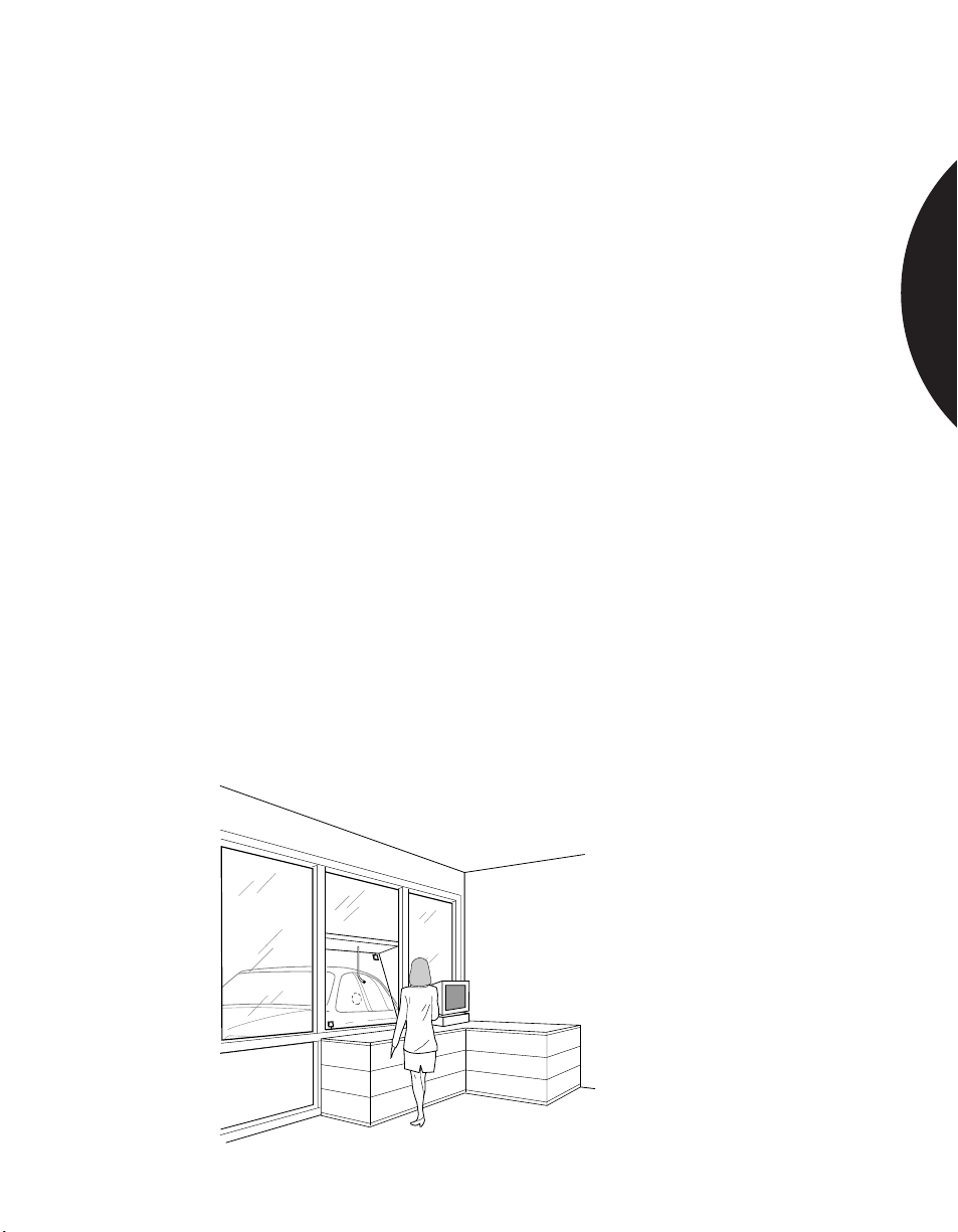
PROTECTING THICK GLASS
GLASSBREAK SENSORS
APPLICATION
INSTALLATION
RECOMMENDED
PRODUCTS
Acoustic sensors and shock sensors are rated for glass thicknesses up to 1/4 in.
(6.4 mm). Some installations may have glass thicker than 1/4 in., yet the customer
still wants glass break detection.
The 5725T ShatterSwitch can be used to protect thicker glass with some reduction
in range. The ShatterPro II is not designed to protect thicker glass. Its
effectiveness will be reduced if protecting thick glass. If ShatterPro II acoustic
sensors are used, the end-user should be warned that capture rate is reduced as much
as 50%.
Shock sensors may be used on thick glass if they are thoroughly tested. Thick
glass absorbs much of the shock energy from a break, and therefore is more of a
challenge for glass break detection.
For on-the-glass shock sensors, mount the sensor in a corner of the glass
approximately 1 in. (2.54 cm) in from the corner. Test the sensor by rapping the far
opposite corner of the glass with a screwdriver handle. The sensor must trip to this
rap test. If the sensor fails to trip, mount additional sensors in the other corners
until at least one sensor trips to rapping the glass at every point on the window.
Frame mounted shock sensors are tested in the same manner. Sensors such as the
5425 have a sensitivity adjustment to increase range of the sensor if needed. For
best false alarm immunity, set sensitivity no higher than half-way. Use additional
sensors as needed.
For shock sensor protection use the 5115/20 mounted on the glass, or the 5425
mounted on the frame. The 5426 shock sensor also has a built-in reed switch with
magnet for detecting forced opening of a door or window. For acoustic sensor
protection, use the 5725T ShatterSwitch and mount within six feet of the farthest
point of the protected glass.
1.21
Page 22
.........................................................................................................................................................................
Phone: 800.894.0412 - Fax: 888.723.4773 - Web: www.clrwtr.com - Email: [email protected]
Commercial Applications
PROTECTING WINDOWS WITH FILM
GLASSBREAK SENSORS
APPLICATION
INSTALLATION
RECOMMENDED
PRODUCTS
In sunny climates some commercial windows will have a tinting film attached to
the glass.
Sometimes, commercial windows also have a plastic film attached to the glass to
prevent shattering from impacts or bullets. This “armor-coated” glass can be found
in bank drive-up windows, in some retail stores, and in other vulnerable buildings.
Acoustic sensor range is not effected by tinting film, so any acoustic sensor can be
used.
Shock sensors are also unaffected by tinting film. For on-the-glass sensors, cut
away the film where the sensor will be placed so that the mounting tape is affixed
to the glass itself and not to the film.
Armor-coating will reduce acoustic sensor range by about 50%. This is particularly
true if the armor-coating is applied to laminated glass. If protecting armor-coated
glass, mount the acoustic sensor 50% closer than the specified range, and confirm
coverage with the hand-held tester. Additional sensors may be needed since the
sensors are mounted closer to the glass.
Armor-coated glass will also reduce shock sensor range. When using shock sensors,
thoroughly test the installation by rapping the glass in the far opposite corner of
the glass from the sensor. If the sensor does not trip to the rap test, add additional
sensors at other corners of the window until at least one sensor trips to a rap at any
place on the window.
Any Sentrol shock or acoustic sensor, as long as the installation guidelines above
are followed.
Plate, Tempered
Laminated Glass Tinted Armor Coated
Acoustic Spec. Range 100% 100% 50% or less
Shock Sensors Required 1 1 Double the sensors
1.22
Page 23
.........................................................................................................................................................................
Phone: 800.894.0412 - Fax: 888.723.4773 - Web: www.clrwtr.com - Email: [email protected]
Commercial Applications
PROTECTING ROOMS WHEN CLEANING CREWS
ARE PRESENT
APPLICATION
INSTALLATION
RECOMMENDED
PRODUCTS
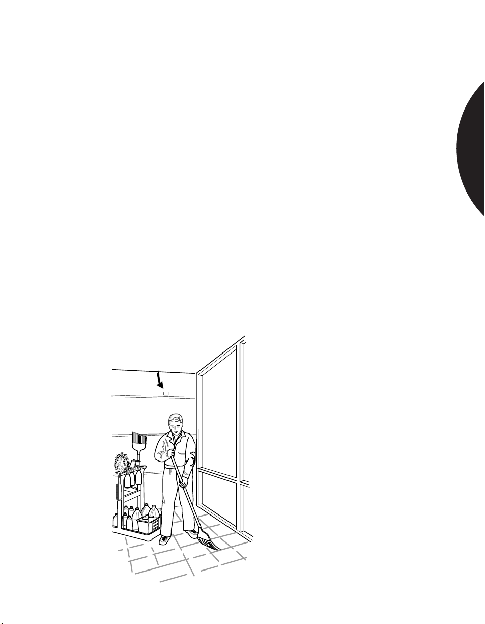
Often, the perimeter loop of the security system is armed when cleaning crews are
in a building. If acoustic sensors are armed, they will be listening to all sounds,
including those made by night cleaning crews. Acoustic sensors are most likely to
false alarm to multiple sounds. The cleaning crews produce a combination of
sounds from vacuums, floor polishers, and clattering garbage cans, all of which
combine to cause false alarms for some sensors in some applications.
Shock sensors provide the best false alarm immunity for a building when it is
occupied. Shock sensors are often economically impractical, however, due to the
number of windows to be protected. Also, in applications where appearance is
important, the use of multiple shock sensors may not be an option.
Sentrol’s ShatterPro Plus 5885 provides an acoustic solution to noisy cleaning
crews. The 5885 is a motion sensitive acoustic sensor that combines a passive
infrared sensor with a glassbreak sensor. When a noisy occupant enters the field of
view of the PIR the glassbreak sensor is disabled for 70 seconds. This prevents
false alarms due to loud noises such as vacuums or floor buffers. The glassbreak
sensor is activated after the occupant leaves the field of view. The 5885 makes 24
hour acoustic applications possible.
For false alarm immunity when night cleaning crews are present, the ShatterPro
Plus 5885 will provide trouble-free performance in most applications. Other
reliable solutions are shock sensors like the 5120 or 5414.
GLASSBREAK SENSORS
1.23
Page 24
.........................................................................................................................................................................
Phone: 800.894.0412 - Fax: 888.723.4773 - Web: www.clrwtr.com - Email: [email protected]
Commercial Applications
PROTECTING PLASTIC WINDOWS
GLASSBREAK SENSORS
APPLICATION
INSTALLATION
RECOMMENDED
PRODUCTS
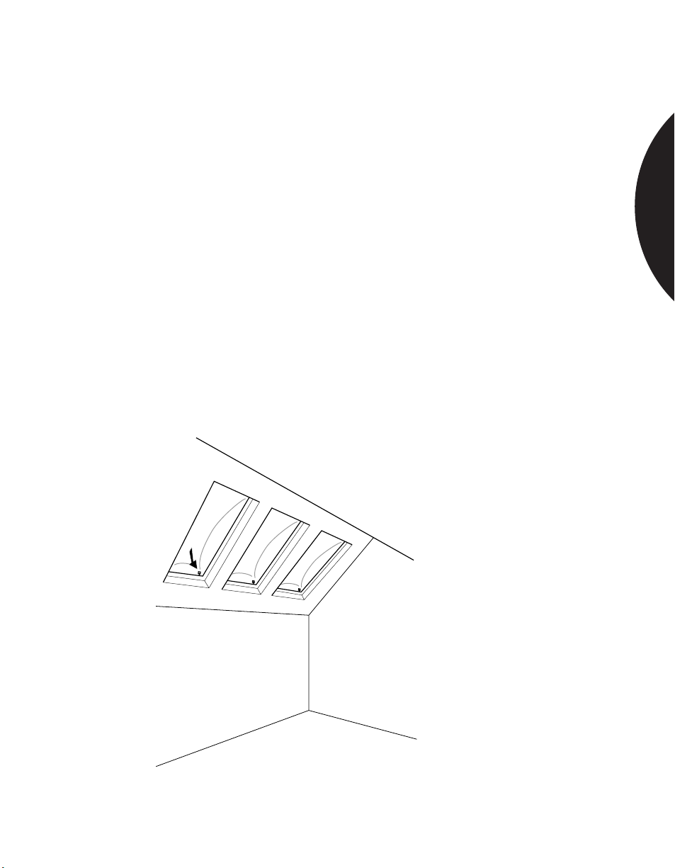
Many windows in commercial installations are made of Plexiglas™, Lexan™, or
other types of plastic. Unfortunately, this eliminates the use of acoustic glassbreak
sensors, since they are designed to detect breaking glass, not plastic. For protecting
plastic windows, it is safest to use a shock sensor.
Note: The plastic material will absorb much of the shock energy from a break.
The range of a shock sensor on plastic is typically 50% less than the range on glass.
A shock sensor with 7 ft. (2.13 m) of range on glass would generally have 3-1/2 ft.
(1.07 m) of range on a plastic window or skylight.
If you are unsure whether the window to be protected is plastic or glass, look for
scratches. Scratches typically indicate a plastic window.
Mount the shock sensor in a corner of the window, 1in. (2.54 cm) from the frame.
Shock frequencies concentrate in the corners.
When protecting plastic windows, it is essential to thoroughly test the sensor by
rapping the far opposite corner. If the sensor trips to the rap test, the sensor range
is sufficient to detect an actual break-in.
Use a Sentrol 5115/20 shock sensor if 3-1/2 ft. (1.07 m) range is sufficient. Use two
sensors mounted in opposite corners if additional range is required.
1.24
Page 25

.........................................................................................................................................................................
Phone: 800.894.0412 - Fax: 888.723.4773 - Web: www.clrwtr.com - Email: [email protected]
CHOOSING THE APPROPRIATE PIR
The following chart is intended to help you match the appropriate Sentrol PIR with your particular
installation. The charts on pages 32 and 33 list the specifications for the PIR.
SENTROL PIR RESIDENTIAL
...................................................................................................
Model 6351 35' x 35' room
Sharpshooter
DesignLine
™
™
Wall or corner mounted
90° wide angle
Pet alley, vertical barrier
...................................................................................................
Model 6255 30' x 30' room
SureShot
™
Mounts 1/8" from ceiling
Wall, corner or ceiling
Pet alley, curtain
40' single spot
...................................................................................................
Stairwell coverage
Model 6255FM Pre-wired wall or ceiling
SureShot™ Flush Mount Retro flush mount
...................................................................................................
Model 6155 45' x 45' room
Sharpshooter
™
Wall or corner mounted
Pet alley, curtain
90' long range
Extra wide angle
...................................................................................................
Model 6155CT Cold climates: garages
Sharpshooter™ CT and vacation homes
...................................................................................................
Model 6085 Garages
Sharpshooter™ Wire Cage
...................................................................................................
Model 6155XT Warm climates
Sharpshooter™ XT Unstable environments
(captures within 1˚C contrast)
(uses Quad technology)
...................................................................................................
Model 6165 Compatible with most
Wireless Sharpshooter
(back box for transmitter available)
...................................................................................................
Model 6187CTX
Industrial Sharpshooter
™
wireless systems
Same applications as 6155
™
(operates to –40˚C)
(cast metal housing)
...................................................................................................
Model 6197
Intrinsically Safe PIR
...................................................................................................
Model 6198
Nonincendive PIR
...................................................................................................
COMMERCIAL INDUSTRIAL
35' x 35' room
Wall or corner mounted
90° wide angle
Pet alley, vertical barrier
Mounts 1/8" from ceiling
30' x 30' room
Wall, corner or ceiling
Pet alley, curtain
40' single spot
Stairwell coverage
Pre-wired wall or ceiling
Retro flush mount
45' x 45' room
Wall or corner mounted
Curtain
90' long range
Extra wide angle
Single gang plate w/swivel
Cold climates Cold climates
Unheated property Unheated warehouses
Vandal protection Vandal protection
Gymnasiums
Warm climates Warm climates
Unstable environments
Compatible with most wireless systems
Same applications as 6155
Outdoors to control Outdoors to control
CCTV or local alarm CCTV or local alarm
Warehouses Food processing plants
Locker rooms Underground parking lots
Underground parking lots Dusty environments
Dusty, cold or wet areas Cold or wet areas
Hazardous areas with Hazardous areas
ignitable atmospheres for use in
Government sites Class I, II, & III
Pharmaceutical labs Division 1-2
Oil refineries Groups A, B, C, D, E, F
Grain elevators and G
Hazardous areas; for
use in Class I Division 2
Groups A, B, C, and D
(only)
Introduction
SPACE DETECTION
2.2
Page 26

.........................................................................................................................................................................
Phone: 800.894.0412 - Fax: 888.723.4773 - Web: www.clrwtr.com - Email: [email protected]
Introduction
CHOOSING THE APPROPRIATE PIR
The following chart is intended to help you match the appropriate Aritech PIR with your
particular application.
ARITECH PIR RESIDENTIAL
...................................................................................................
Model AP125/AP126 33' x 40' room
(Form A)/(Form C) Corner or wall mounted
Mirror Optic Wall Mount 5 curtains at 33ft. each
...................................................................................................
Model AP425/426 50' x 65' room
(Form A)/(Form C) Corner or wall mounted
Mirror Optic Wall Mount 7 curtains at 50ft. each
...................................................................................................
Model PR361/PR363 50' diameter-360° coverage
(Form A)/(Form C) Ceiling mount - low profile
Ceiling Mount 9 curtains at 25ft. each
...................................................................................................
Model PR569 (Form C)
Commercial Ceiling Mount
...................................................................................................
Model PR633/643
200 ft Long Range
80 ft Wide Angle
...................................................................................................
Range can be reduced to 20ft.
Mounting height 6'-10'
Mirror mask allows
coverage patterns
Mounting height 6'-10'
Mounting height 7'-12'
COMMERCIAL INDUSTRIAL
33' x 40' room
Corner or wall mounted
5 curtains at 33ft. each
Range can be reduced to 20ft.
Mounting height 6'-10'
50' x 65' room
Corner or wall mounted
7 curtains at 50ft. each
Mirror mask allows
coverage patterns
Mounting height 6'-10'
50' diameter-360° coverage
Ceiling mount - low profile
9 curtains at 25 ft. each
Mounting height 7'-12'
60' diameter-360° coverage 60' diameter-360°coverage
Ceiling Mount Ind./Comm. Ceiling Mount Ind./Comm.
12 curtains at 30 ft. each 12 curtains at 30ft. each
Mounting height 7'-15' Mounting height 7'-15'
Coverage patterns: Coverage patterns:
- Full 360° - Full 360°
- 90° Curtain - 90° Curtain
- ”L“ Turn Pattern - ”L“ Turn Pattern
- Corridor Intersection - Corridor Intersection
200' Long Range 200' Long Range
80' Wide Angle 80' Wide Angle
Wall Mount Wall Mount
12 selectable coverage 12 selectable coverage
patterns patterns
Mounting height 6'-10' Mounting height 6'-10'
SPACE DETECTION
2.3
Page 27
.........................................................................................................................................................................
Phone: 800.894.0412 - Fax: 888.723.4773 - Web: www.clrwtr.com - Email: [email protected]
Introduction
SPECIFICATIONS
6150 6150XT 6160 6170
Series Series Series Series
Electrical
Voltage
3 Volt & 9 Volt Wireless
7 to 16 VDC
7 to 10 VDC
9 to 16 VDC
..............................................................................................................................
..............................................................................................................................
...............................................................................................................................
..................................................................................................................
✔✔
9.5 to 30 VAC/DC
Current
20uA typical
8mA typical, 10mA max
18mA typical, 20mA max 6179
..............................................................................................................................
.................................................................................................................
................................................................................................................
✔✔
50mA max
Alarm Loop Rating
16 VDC, 50mA
..........................................................................................................................
✔✔N/A 6177
30 VAC/DC, 1A; 125 VDC 50mA 6179
Alarm Output
Fail Safe contacts with 10 Ohms in series
Form A, normally closed (SPST) 6155, 6155CT, 6155AL 6155XT
Form C, normally closed and open (SPDT) 6157, 6157CT, 6157AL 6157XT 6177
Form C, no resistance in series 6179
.........................................................................................................
.............................................................................................
.........................................................................................................
Normally high and normally low
Alarm Duration
2 to 5 seconds
............................................................................................................................
✔✔
2 to 5 seconds in walktest mode
5 to 9 seconds in RF mode
.............................................................................................................
0 to 90 seconds retriggerable, adjustable 6179
Cover Tamper Contacts
Normally closed, rating: 50mA, 16-volts, no resistance
................................................................................
✔✔✔✔
Normally closed, rating 50mA, 16-volts, 10 Ohms in series
Environmental
Operating Temperature
0°F to 122°F (-17°C to 50°C) 6155, 6155AL
.............................................................................................................
6157, 6157AL
✔✔✔
-40°F to 122°F (-40°C to 50°C) 6155CT, 6157CT
✔
✔
✔
✔
6177
✔
6177
✔
SPACE DETECTION
Humidity
Dust Proof, Water Resistant
.............................................................................................................
10% to 90% noncondensing ✔✔✔
RFI Immunity
Greater than 10V meter from 0 to 1000 MHz
............................................................................................
✔✔✔✔
Lightning Immunity
2.5KV, 2 joules max energy impulse,
1 msec rise/50 msec decay
...............................................................................................................
Static Discharge 20KV
✔✔ ✔
✔✔✔✔
✔
2.4
Page 28

.........................................................................................................................................................................
Phone: 800.894.0412 - Fax: 888.723.4773 - Web: www.clrwtr.com - Email: [email protected]
Introduction
SPECIFICATIONS
6180 6190 6250 6255FM 6350
Series Series Series Series Series
Electrical
Voltage
3 Volt & 9 Volt Wireless
7 to 16 VDC
7 to 10 VDC
9 to 16 VDC 6197
..............................................................................................................................
..............................................................................................................................
...............................................................................................................................
9.5 to 30 VAC/DC
Current
20uA typical
..............................................................................................................................
8mA typical, 10mA max
18mA typical, 20mA max
50mA max 6197
Alarm Loop Rating
16 VDC, 50mA
30 VAC/DC, 1A; 125 VDC 50mA
Alarm Output
Fail Safe contacts with 10 Ohms in series
Form A, normally closed (SPST) 6198 6255 6255FM 6351, 6352
Form C, normally closed and open (SPDT)
Form C, no resistance in series
Normally high and normally low
Alarm Duration
2 to 5 seconds
2 to 5 seconds in walktest mode
5 to 9 seconds in RF mode
0 to 90 seconds retriggerable, adjustable
Cover Tamper Contacts
Normally closed, rating: 50mA, 16-volts, no resistance
Normally closed, rating 50mA, 16-volts, 10 Ohms in series 6197
Environmental
Operating Temperature
0°F to 122°F (-17°C to 50°C)
-40°F to 122°F (-40°C to 50°C)
Humidity
Dust Proof, Water Resistant
10% to 90% noncondensing
RFI Immunity
Greater than 10V meter from 0 to 1000 MHz
Lightning Immunity
2.5KV, 2 joules max energy impulse,
1 msec rise/50 msec decay
Static Discharge 20KV
..................................................................................................................
.................................................................................................................
................................................................................................................
..........................................................................................................................
.........................................................................................................
.............................................................................................
.........................................................................................................
............................................................................................................................
.............................................................................................................
................................................................................
.............................................................................................................
.............................................................................................................
............................................................................................
...............................................................................................................
✔
✔
6198
6198
✔✔✔
✔✔✔
✔✔ ✔ ✔✔
✔
6197 6257 6257FM 6353
✔✔ ✔✔✔
✔
✔
6198
6198
6197-PIR only
✔✔
6255, 6257 6255FM, ✔
6257FM
6352, 6353
✔✔
✔✔
✔
✔✔
✔✔ ✔ ✔✔
✔✔ ✔ ✔✔
✔✔ ✔ ✔✔
SPACE DETECTION
2.5
Page 29

.........................................................................................................................................................................
Phone: 800.894.0412 - Fax: 888.723.4773 - Web: www.clrwtr.com - Email: [email protected]
Introduction
PIR INSTALLATION GUIDELINES
SPACE DETECTION
Passive Infrared (PIR) motion sensor technology provides one of the most reliable
and cost effective methods for protecting spaces in the home, office or industrial
facility. PIR detectors sense temperature contrasts between a relatively stable
background and hotter or colder objects moving across their fields of view. They
emit no energy of their own. They merely “see” infrared images.
Sentrol, the world leader in security and life safety sensor devices, offers a
complete line of PIRs suitable for every application — residential, commercial,
and industrial. Sentrol PIR detectors fit compactly, aesthetically and unobtrusively
into any environment. This application section is designed to help you select the
appropriate PIR for your particular needs.
IMPORTANT DOs AND DON’Ts FOR ALL INSTALLATIONS —
residential, commercial or industrial.
• Do position the PIR so that any intruder must cross the PIR’s field of view. To
trigger an alarm, an intruder must cross both the positive and negative elements
of one zone of the PIR’s sensor.
• Do pre-test the PIR in the direction of likely intruder motion and walk-test
monthly.
• Do locate the PIR so that valuables are well within its coverage pattern.
• Do terminate each protection zone on a solid object such as a wall or floor
whenever possible. This provides maximum detection.
• Do mask zones around fireplaces because a smoldering log can change
temperature quickly if it bursts into flames.
• Do use an industrial PIR in locations where a standard PIR may be affected by
water, steam or oil.
• Don’t aim PIR detectors at sources of rapid heating or cooling. These include
forced air ducts, space heaters, direct sunlight, strong white lights and mirrors
that can reflect strong lights.
• Don’t obstruct the PIR’s field of view.
SPACE DETECTION
2.6
Page 30
.........................................................................................................................................................................
Phone: 800.894.0412 - Fax: 888.723.4773 - Web: www.clrwtr.com - Email: [email protected]
Introduction
OTHER INSTALLATION TIPS
Pre-wiring — Pre-wiring allows you to work with the builder in the planning
stage to determine optimum locations for sensors. It will also allow you to avoid
many of the hazards inherent in post-construction installations i.e. drilling through
the electrical cables, plumbing, and duct-work hidden in existing walls.
When wiring after construction, compromises are usually the norm — existing
walls, lighting fixtures, air conditioning ducts, and other obstacles often determine
sensor and control panel locations. Compromises such as these can leave “blind
spots” in security installations.
Pre-wiring also allows you to run extra wires, a practice rarely seen in “post-wired”
systems. Extra wires give the home or business owner the flexibility to easily add
other features at a later date.
Pre-wiring allows you to avoid many of the hazards inherent in post-construction
installations hazards such as water supply pipes, drain-waste-vent pipes, heating
and cooling duct work, venting duct work for kitchens and bathrooms, and high
voltage wiring.
Sensors are now available that will fit into standard outlet boxes just like a light
switch. Sentrol offers two products for prewiring applications. The Flush Mount
SureShot PIR fits into a standard single gang box, remodel box or rough-in plate in
two easy steps. You simply connect the wires to the proper terminals on the back
of the unit, then screw the unit into an outlet box like you would a switch. The
Sharpshooter also has a recessed bezel kit available as an accessory.
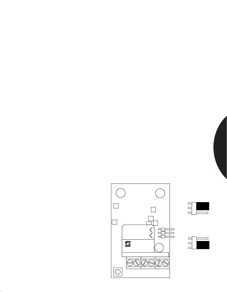
Reducing False Alarms — Sentrol PIRs allow selection of one- or two-zone
detection. Each zone is made up of two fields of view — one positive and one
negative. With one zone selected, an alarm will be indicated when an intruder
moves across one positive and one negative field. With two zones selected, an
intruder must cross the
positive and negative fields
of each of the two zones
before an alarm will be
indicated. Two-zone
detection is recommended
(except when using long
range and curtain lenses) to
reduce chances of false
alarm. One- and two-zone
detection is selected by
simply moving the jumper
as indicated in the diagram.
Two Zones
Remove
(4 pulse)
for
One Zone
Test
(2 pulse)
SENTROL, INC.
SHARPSHOOTER
6155XT
NC COM TAMP TAMP
+–
Two Zone
One Zone
SPACE DETECTION
2.7
Page 31
.........................................................................................................................................................................
Phone: 800.894.0412 - Fax: 888.723.4773 - Web: www.clrwtr.com - Email: [email protected]
Introduction
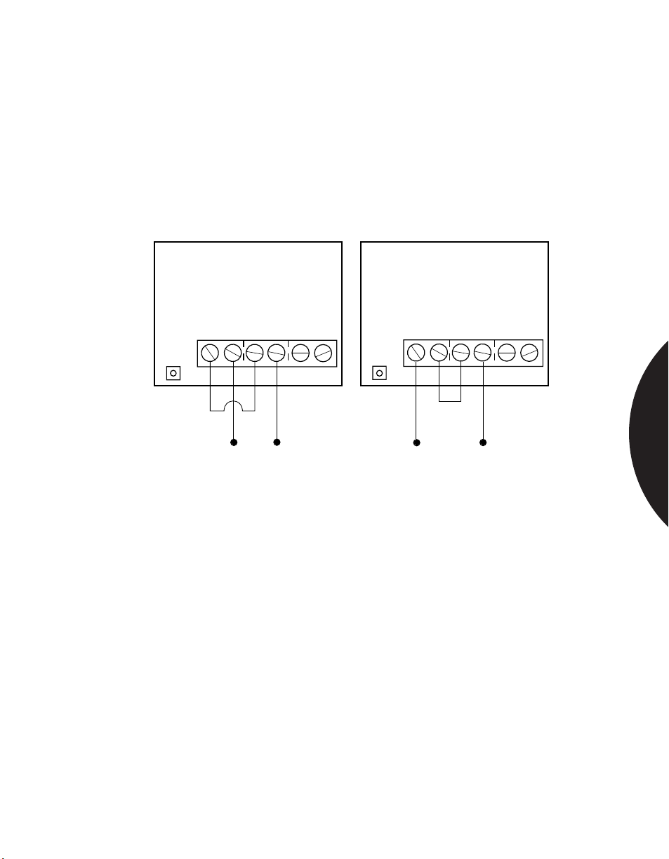
Wiring a Terminal Block With Shared Terminals — The SureShot and some
older style Sharpshooter PIRs have SPDT (single pole double throw) contacts in
which the “normally open” (N.O.) and one of the “tamper” (TAMP.) terminals are
shared. In other words, one “TAMP”. terminal is shared with “N.O.”
When wiring a tamper switch in series with the alarm output in the normally
closed configuration, care must be taken to wire the terminals as shown in the
“correct” diagram below. If the jumper wire is placed from the “normally closed”
(N.C.) terminal to “N.O.”, as shown in the “incorrect” diagram, no alarm will
sound.
INCORRECT
NC COM T/NO TAMP
+ –
CORRECT
NC COM T/NO TAMP
+ –
When wiring tamper switch in series with the normally closed alarm loop, place the jumper
between COM and T/NO.
Supervising the Loop — If a resistor is placed at the end of a protection zone (at
the last unit in the line), that zone becomes a supervised loop. A small amount of
current can always be applied to that loop, allowing it to “watch” the wiring at all
times. The system can then be programmed to give a warning light or audible
alarm if it is tampered with during daytime hours. “Supervising the Loop,”
therefore, is a security technique used to prevent internal tampering.
To supervise a loop in the normally open configuration, you simply remove the
resistor from the terminal block in the control panel and place it across the N.O.
and COM. terminals of the last security device on the line.
These Installation Tips apply to all environments — residential, commercial and
industrial. The following sections provide specifics about commonly encountered
applications in different environments.
SPACE DETECTION
2.8
Page 32
.........................................................................................................................................................................
Phone: 800.894.0412 - Fax: 888.723.4773 - Web: www.clrwtr.com - Email: [email protected]
Commercial Applications
PROTECTING MUSEUMS
APPLICATION
INSTALLATION
RECOMMENDED
PRODUCTS
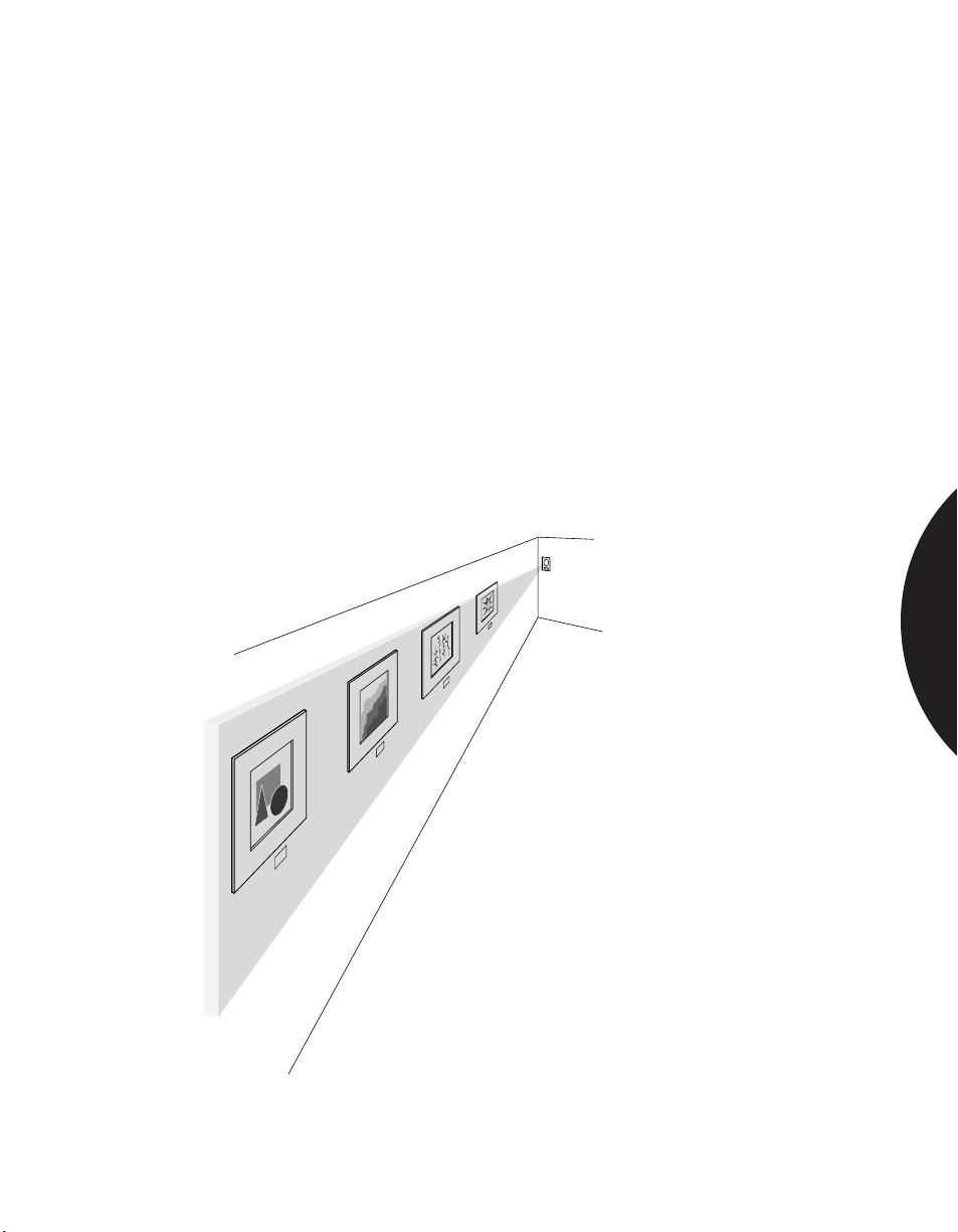
A PIR can effectively protect areas where the presence of valuable items increases
the risk of theft or vandalism.
A PIR can be mounted to the side of a wall of paintings, for example, to trigger an
alarm or recorded message to stay back (see Figure). A lens with a curtain pattern
provides blanket coverage of areas of entry. A vertical barrier lens discourages
intruders from attempting to crawl under the PIR’s field of view.
A PIR can be mounted behind a painting or wall hanging to sound an alarm if the
painting is removed.
Always test each sensor after installation to ensure correct operation.
The AP425 provides true curtain lens protection and is ideal for this application.
SPACE DETECTION
Creating a curtain of protection using the AP425
2.9
Page 33
.........................................................................................................................................................................
Phone: 800.894.0412 - Fax: 888.723.4773 - Web: www.clrwtr.com - Email: [email protected]
Commercial Applications
PROTECTING OFFICE FOYERS
APPLICATION
INSTALLATION
RECOMMENDED
PRODUCTS
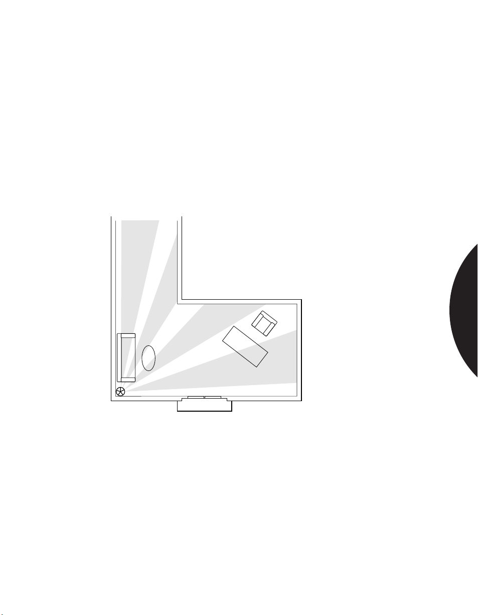
Large office foyers can be difficult to protect with a single PIR. For large office
foyers where the range of a single PIR may not be sufficient, a ceiling mount PIR
mounted in the corner or in the center of the room may be a better way to
protect it.
The illustration shows how a ceiling mount PIR mounted in the corner provides
appropriate coverage of foyers, corridors and hallways.
The PR569 and PR363 Aritech PIR’s are excellent choices in this application.
SPACE DETECTION
Protecting both a foyer and a hallway with one ceiling
PIR mounted in the corner.
2.10
Page 34
.........................................................................................................................................................................
Phone: 800.894.0412 - Fax: 888.723.4773 - Web: www.clrwtr.com - Email: [email protected]
Commercial Applications
PROTECTING SCHOOLS
APPLICATION
INSTALLATION
RECOMMENDED
PRODUCTS
Protecting schools presents a particular challenge to security system installers.
Rooms in schools are typically larger than in other commercial environments
(auditoriums, lecture halls, gymnasiums), and hallways are longer. And a very
important concern is defense against vandalism.
It may also be necessary to protect outdoor areas to prevent unwanted entry at
certain times of the day or night.
PIRs should be located high, near the corners of walls where they are least
conspicuous. Rugged design is a plus.
Outdoor PIRs should be mounted high, out of reach of vandals, in areas where
they will not be exposed to direct sunlight. For outdoor installation see
COMMERCIAL AND INDUSTRIAL OUTDOOR AREAS section.
The 6155 Sharpshooter with 6085 Wire Cage, or the 6187CTX Industrial PIR offer
the best protection against vandalism. The 6187CTX is ideal for areas that may be
exposed to water, high humidity, heat or chemicals, as in school kitchens or shops.
It incorporates a cast metal housing, allowing it to be used indoors or outdoors.
For larger areas and 200 ft hallway coverage use the PR633. It provides 80 ft wide
angle, 40 ft curtain and 200 ft long range coverage patterns. (see page 42)
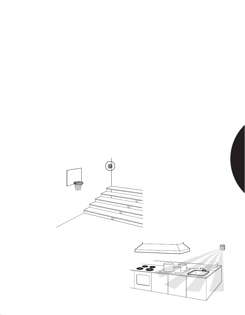
SPACE DETECTION
Using a wire cage (6085) to protect against
vandalism or accidental damage.
The 6187CTX is sealed against
water, dust and grime.
2.11
Page 35
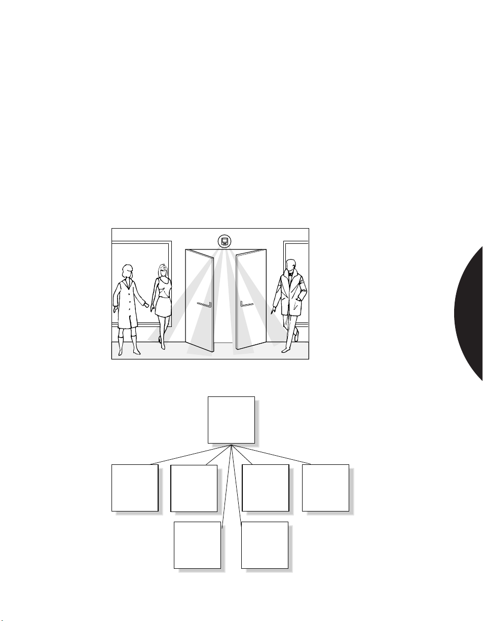
.........................................................................................................................................................................
Phone: 800.894.0412 - Fax: 888.723.4773 - Web: www.clrwtr.com - Email: [email protected]
Commercial Applications
CONTROLLING PERIPHERALS
APPLICATION
INSTALLATION
RECOMMENDED
PRODUCTS
PIRs can be use to control a wide range of peripheral devices such as entry and
exit doors, CCTV cameras, recorded messages, etc.
A Sharpshooter may be used in the look-down mode (see Avoiding Sabotage
Zones) to operate entry and exit doors (Figure 1). A special request-to-exit
Sharpshooter (6179) is available for this application.
A SureShot may be used in a museum to trigger a recorded message to Stand Back.
(See Protecting Museums)
The 6187CTX PIR can be used outdoors to turn on a CCTV camera, or a camera
on a chip, when an intruder is detected (Figure 2).
Any Sentrol PIR can be used to control a peripheral device.
SPACE DETECTION
Figure 1—Using the 6179 in a request to exit application.
PIR
camera
tape
recorder
door
monitor
local
alarm
lights
HVAC
Figure 2—A PIR can be used to control many different devices.
2.12
Page 36
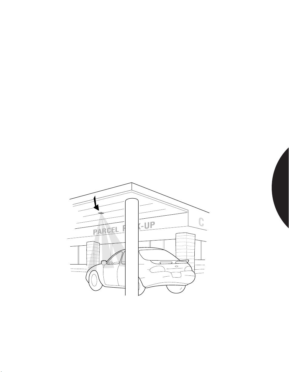
.........................................................................................................................................................................
Phone: 800.894.0412 - Fax: 888.723.4773 - Web: www.clrwtr.com - Email: [email protected]
Commercial Applications
USING A PIR FOR GROCERY STORE PICKUP
APPLICATION
INSTALLATION
RECOMMENDED
PRODUCTS
Grocery stores are often designed with drive through grocery bag pickup lanes.
A PIR with a long range lens mounted on the overhang above the drive-up can be
used to signal the grocery bag attendant with a bell and/or a light when a car pulls
up to the pickup door. The long range lens provides spot detection of automobiles
and minimizes false alarms from people in the walkways next to the pickup lane.
This configuration is designed for local annunciation — not alarm. Note: the PIR
is responding to the heat of the car engine. Upon initial start-up, some car engines
may not generate sufficient heat to trip the PIR. Be sure to localize the PIR by
using a long range lens in this application.
Mount the PIR in the ceiling, directly above the drive.
Make sure conduit openings and mounting holes are well sealed. If conduit is
used, run the conduit out the side or bottom of the unit to keep condensation from
the conduit from draining into the PIR’s housing.
The cast metal housing of the 6187CTX is specifically designed for outdoor
applications. It provides water resistance and reliable detection in temperatures
from -40°C to +50°C (-40°F to +120°F).
SPACE DETECTION
The 6187CTX detects warm car engines crossing a narrow
field of view sending a local alarm to a waiting attendant.
2.13
Page 37
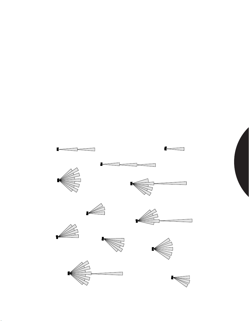
.........................................................................................................................................................................
Phone: 800.894.0412 - Fax: 888.723.4773 - Web: www.clrwtr.com - Email: [email protected]
Commercial & Industrial Applications
PROTECTING LARGE AREAS
APPLICATION
INSTALLATION
RECOMMENDED
PRODUCTS
Factories, supermarkets, sports or concert halls, gymnasiums and warehouses
typically require protection of a very large area. This can require installation of
several PIRs, with consequent material and labor costs.
The PR633 can provide a significant savings in large area protection. With an 80
foot wide angle coverage pattern, a single PR633 can often do the job of several
conventional PIRs. The coverage includes a complete 40 foot curtain and a 200
foot long range field of view which can be enabled when required. The
combination of “step focus” mirror and microprocessor controlled “4D” signal
processing ensures excellent detection at all ranges and trouble-free performance
in these often difficult environments.
Mount the sensor between 6 and 10 feet high. Select the correct sensitivity for
standard wide angle detection. Carry out any fine adjustment using the aiming
mechanism as described in the manual.
Aritech PR633
40 ft (12.2m) 80 ft (24.4m)
80 ft (24.4m)
40 ft (12.2m)
40 ft (12.2m) 80 ft (24.4m)
80 ft (24.4m)
40 ft (12.2m)
200 ft (61.0m)
200 ft (61.0m)
SPACE DETECTION
200 ft (61.0m)
40 ft (12.2m)
80 ft (24.4m)
40 ft (12.2m)
40 ft (12.2m)
80 ft (24.4m)
80 ft (24.4m)
40 ft (12.2m)
200 ft (61.0m)
80 ft (24.4m)
Protect ballrooms, concert halls, warehouses, or factories with PR633.
2.14
Page 38
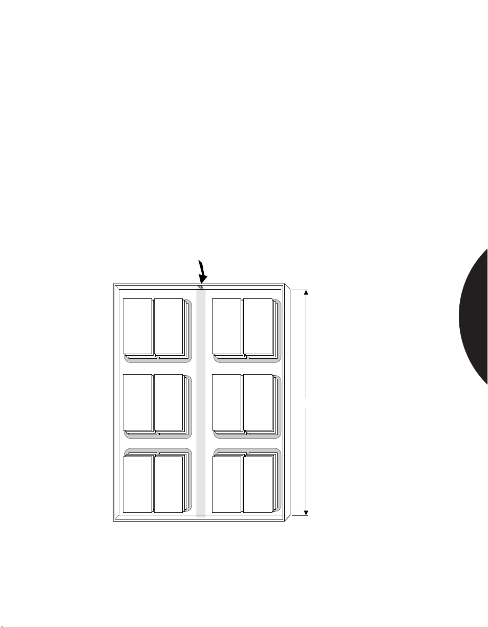
.........................................................................................................................................................................
Phone: 800.894.0412 - Fax: 888.723.4773 - Web: www.clrwtr.com - Email: [email protected]
Commercial & Industrial Applications
LONG RANGE APPLICATIONS
APPLICATION
INSTALLATION
RECOMMENDED
PRODUCTS
In supermarkets, factories and schools it is frequently necessary to protect long
corridors or aisles. The PR633 provides the longest range of any PIR available
(200 ft.) The unique step focus mirror ensures that even at maximum range,
detection is crisp and consistent without any oversensitivity at closer ranges.
Mount the sensor between 6 and 10 feet high. Select the correct sensitivity for
“Curtain /Long Range” detection. Carry out fine adjustment using the aiming
screws as described in the manual. This is very important in this application: a
minor horizontal or vertical re-orientation can result in a major displacement of the
field of view at 200 feet. If detection is not satisfactory at long range, check the
vertical orientation: an uneven wall can make the sensor aim slightly downwards,
reducing range.
Aritech PR633
SPACE DETECTION
200 feet
One PR633 Long Range Unit provides a full 200 foot coverage.
2.15
Page 39
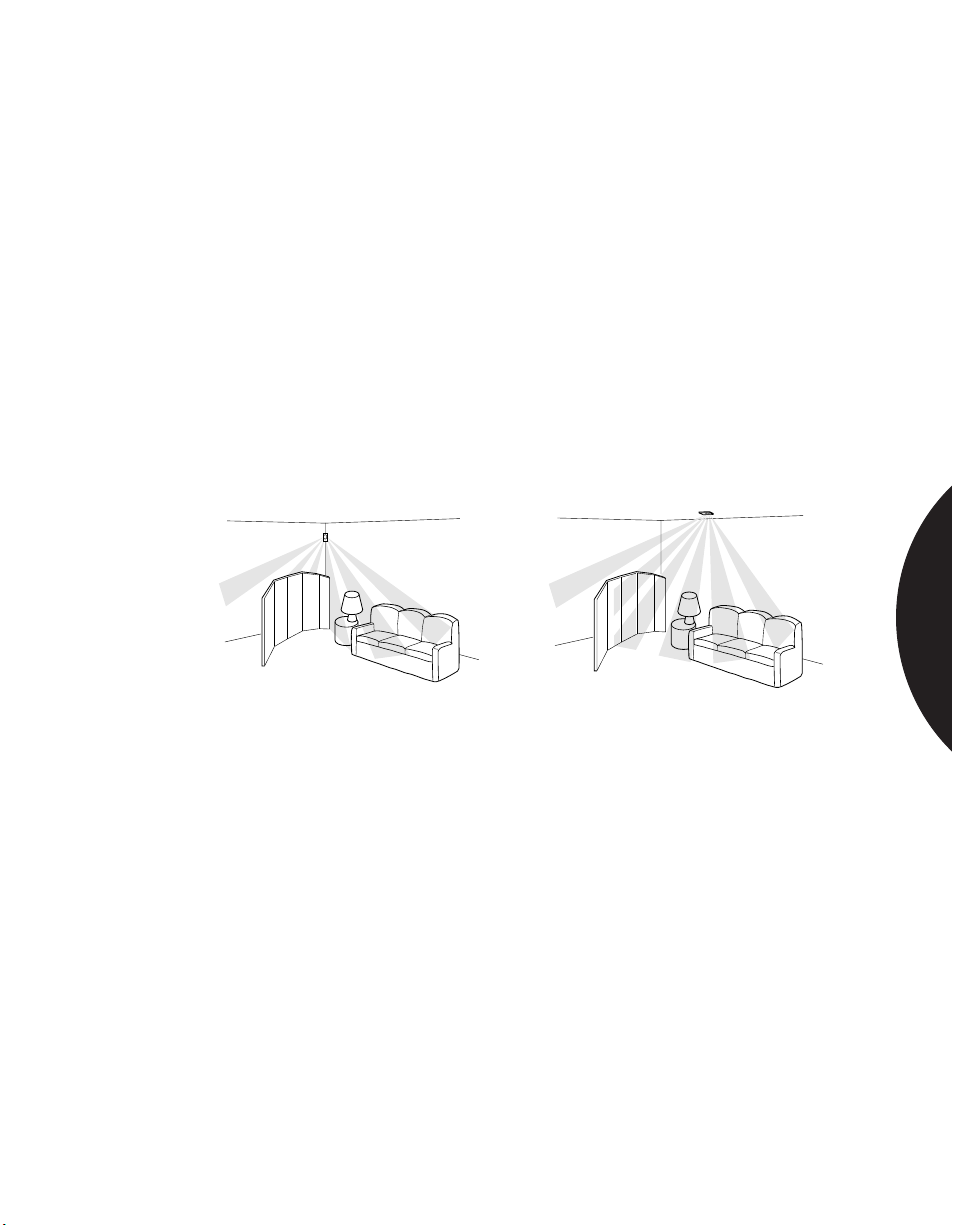
.........................................................................................................................................................................
Phone: 800.894.0412 - Fax: 888.723.4773 - Web: www.clrwtr.com - Email: [email protected]
Commercial & Industrial Applications
PROTECTING OFFICES WITH PARTITIONS,
SHELVING OR OTHER OBSTACLES
APPLICATION
INSTALLATION
RECOMMENDED
PRODUCTS
Partitions, half-walls, shelving, filing cabinets, etc. are typically encountered in the
office environment. The best way to avoid these obstacles while protecting all the
space in a room is to mount a PIR in the ceiling. Sentrol PIRs can also be installed
in drop ceilings.
Position the PIR in a location where partitions will not block the PIR’s coverage
patterns (see Figure 1).
Correct placement is as shown in Figure 2.
Walk-test the installation to ensure correct operation.
Office personnel should be instructed not to move partitions or shelving without
notifying the security consultant.
The 6255 Standard SureShot, 6255FM Flush-Mount SureShot, PR361 and PR569
Aritech PIRs are ideal for this application.
CorrectIncorrect
SPACE DETECTION
Figure 1. Wall mounted PIRs are more
susceptible to blockage by partitions and
shelving.
Figure 2. A ceiling mount PIR can provide
protection from partitions blocking the view.
2.16
Page 40
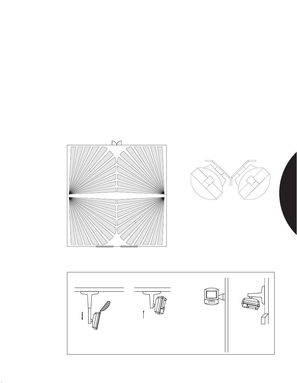
.........................................................................................................................................................................
Phone: 800.894.0412 - Fax: 888.723.4773 - Web: www.clrwtr.com - Email: [email protected]
Commercial & Industrial Applications
USING ACCESSORIES
FOR INCREASED COVERAGE
APPLICATION
INSTALLATION
For uneven walls that may block coverage, or applications where the PIR needs
to look around curtains or other obstacles, brackets can be used to position the PIR
as needed.
Double brackets may be mounted with PIRs aimed in opposite directions to
achieve 180° coverage as shown in Figure 1.
Figure 2 shows two such applications and their corresponding coverage patterns.
Figure 3 shows how you can extend a PIR away from a wall or ceiling so it looks
around window coverings and down hallways.
RECOMMENDED
PRODUCTS
The 6155 Sharpshooter with the 6069 mounting bracket, or the 6084 Ceiling/Wall
Bracket with Swivel.
Figure 1. Using double brackets for 180°
coverage with the 6155.
Figure 2.
Ceiling/Wall Bracket
Wall
Door
SPACE DETECTION
Pull down to snap on
sighting mirror and
adjust coverage
Figure 3.
Push up to snap
into fixed position
2.17
Page 41
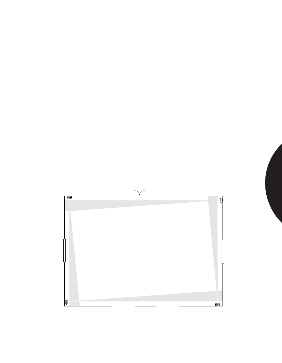
.........................................................................................................................................................................
Phone: 800.894.0412 - Fax: 888.723.4773 - Web: www.clrwtr.com - Email: [email protected]
Commercial & Industrial Applications
PERIMETER DETECTION
APPLICATION
INSTALLATION
RECOMMENDED
PRODUCTS
PIRs can be sensitive to direct sunlight. This poses a problem when protecting a
room with several windows. Windows can limit the choice of coverage patterns and
mounting locations. However, using four Sharpshooters with or Aritech AP425
units allows you to protect the entire perimeter of such a room.
Mount the Sharpshooter swivel bracket near a corner as shown in Figure 1.
Connect the back case to the bracket and snap in the sighting mirror. Viewing the
coverage pattern through the mirror, angle the PIR slightly toward the center of
the room. The outside coverage zone should run parallel to, but not touch, the wall
to be protected. With proper aiming you can reduce the unprotected space near
the wall. You may want to mask the look-down zones on the 6071 long range lens.
Using the AP425, insert the mirror mask over that portion of the mirror that “looks
out” into the room.
Walk-test the installation to ensure correct operation.
The 6155 Sharpshooter equipped with the 6071 90' (27.4 m) long range or 6073
vertical barrier lenses is ideal. The AP425 has excellent curtain protection since
half of its pattern is easily masked.
SPACE DETECTION
Setting up perimeter protection with the 6155 or AP425.
2.18
Page 42
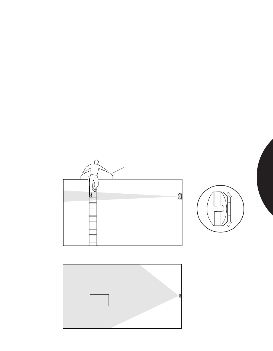
.........................................................................................................................................................................
Phone: 800.894.0412 - Fax: 888.723.4773 - Web: www.clrwtr.com - Email: [email protected]
Commercial & Industrial Applications
PROTECTING AGAINST
ROOF OR SKYLIGHT ENTRY
APPLICATION
INSTALLATION
RECOMMENDED
PRODUCTS
A PIR with a curtain pattern can effectively protect areas under skylights or where
the presence of valuable items increase the danger of entry through the roof. The
curtain lens will blanket the area where entry is most likely to occur.
The 6155 Sharpshooter can be equipped with a curtain lens for this application.
The mirror sighting system helps you achieve the best coverage. Note: Make
certain the unit will not be subjected to early morning or late evening light
entering through the windows and striking the detector directly.
For a curtain pattern, mount the swivel bracket 90° from vertical. Attach the back
case of the sensor to the bracket and snap in the sighting mirror. After positioning
for best coverage, tighten the bracket in place and recheck positioning with the
mirror. Then snap on the front cover of the sensor with the curtain lens installed.
Unit should appear rotated 90° from typical vertical position.
Pass your hand up and down in front of the Sharpshooter to trip the alarm and
ensure correct operation.
The 6155 Sharpshooter equipped with a 6073 curtain lens is ideal for this
application.
Skylight
SPACE DETECTION
Top View
6155 Sharpshooter
Side View. 6155 is turned 90° from standard, vertical position
with curtain lens.
Skylight
Top View of curtain lens.
2.19
Page 43
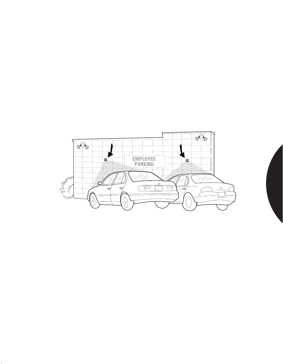
.........................................................................................................................................................................
Phone: 800.894.0412 - Fax: 888.723.4773 - Web: www.clrwtr.com - Email: [email protected]
Commercial & Industrial Applications
PROTECTING OUTDOOR AREAS
APPLICATION
INSTALLATION
RECOMMENDED
PRODUCTS
There are many applications for space protection outdoors. Most of them stem
from the need to protect property that is at risk. Parking lots, outdoor shopping
areas, outdoor shipping areas, outdoor garden shops, auto dealerships, aircraft
hangers, perimeters of military installations, and public utility installations are
examples of such applications.
Refer to “TIPS FOR INSTALLING THE 6187CTX OUTDOORS” from the
sales sheet on page 54.
The Sentrol 6187CTX PIR is specifically designed for outdoor applications.
SPACE DETECTION
The 6187CTX comes in a cast aluminum gasket-sealed housing,
protecting it against snow, rain, dirt, etc. It is rated to operate
to -40°C.
2.20
Page 44
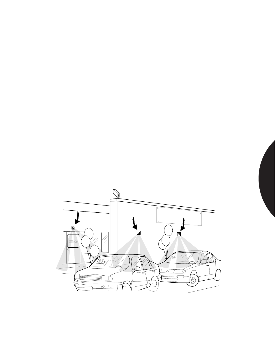
.........................................................................................................................................................................
Phone: 800.894.0412 - Fax: 888.723.4773 - Web: www.clrwtr.com - Email: [email protected]
Commercial & Industrial Applications
ACTIVATING A CCTV CAMERA
APPLICATION
INSTALLATION
RECOMMENDED
PRODUCTS
A PIR can be used to activate a CCTV camera that monitors outdoor parking lots,
auto dealerships, shopping areas, shipping areas, garden shops, aircraft hangers,
perimeters of military installations, and public utility installations.
In this application the PIR does not directly activate a central station alarm.
Rather, it alerts a guard station and/or automatically starts a CCTV recording
device. This prevents false alarms due to birds and other animals that might enter
the detector’s coverage area.
Connect a Sentrol 6187CTX PIR unit to local alarm switch in a central station or a
CCTV camera.
Mount the PIR approximately 7 ft. (2.13m) high on a flat surface to discourage
rodents or birds from perching.
Make sure conduit openings and mounting holes are well sealed. If conduit is
used, run the conduit out the side or bottom of the unit to keep condensation from
the conduit from draining into the PIR’s housing.
Avoid direct sunlight on the plastic lens.
Keep away from branches that may impede PIR’s coverage pattern.
Use the 6187CTX for outdoor applications.
SALE
SPACE DETECTION
The 6187CTX comes in a cast aluminum gasket-sealed housing,
protecting it against snow, rain, dirt, etc. It is rated to operate
to -40°C.
2.21
Page 45
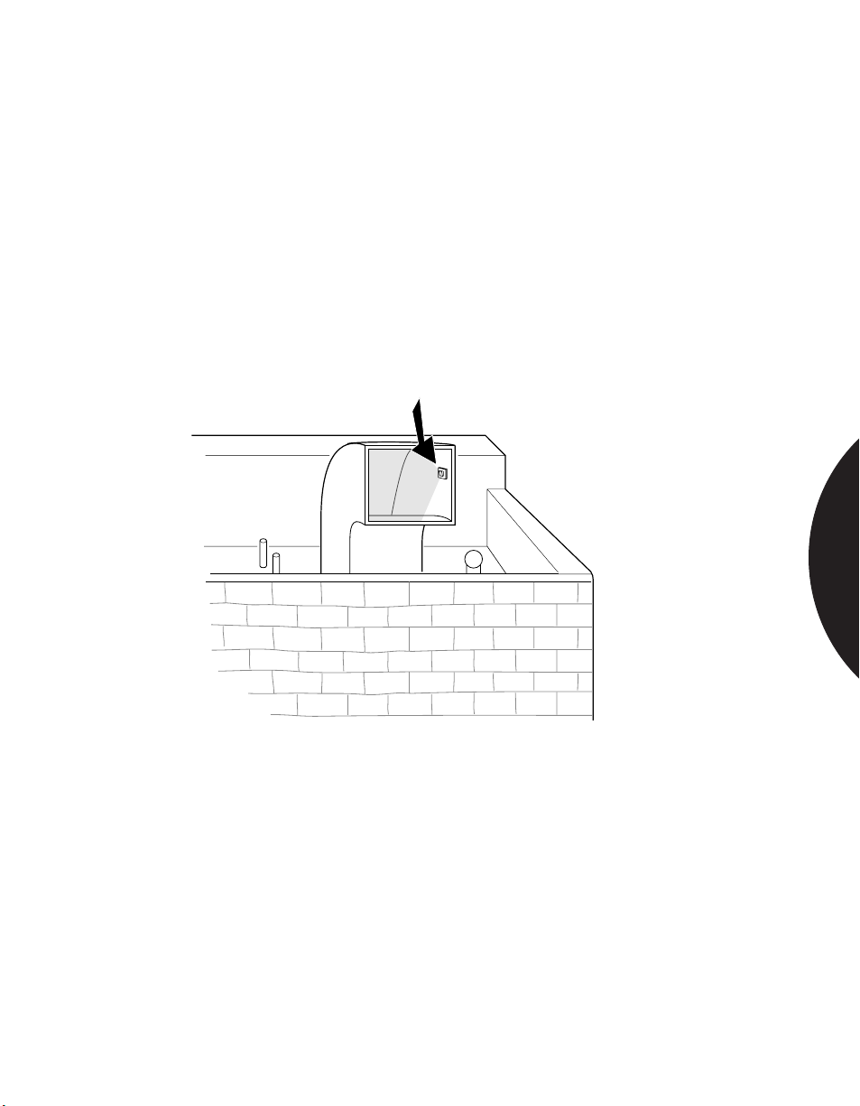
.........................................................................................................................................................................
Phone: 800.894.0412 - Fax: 888.723.4773 - Web: www.clrwtr.com - Email: [email protected]
Commercial & Industrial Applications
PROTECTING AGAINST
ROOFTOP HVAC VENT ENTRY
APPLICATION
A PIR with a curtain pattern can effectively protect against rooftop HVAC vent
entry. The curtain lens will blanket the area where entry is most likely to occur.
INSTALLATION
RECOMMENDED
PRODUCTS
The 6187CTX can be equipped with a curtain or standard lens for this application.
Attach back of case directly to one of the walls of the HVAC opening.
Pass your hand across the front of the detector to trip the alarm and ensure correct
operation.
The 6187CTX equipped with a curtain lens.
SPACE DETECTION
The 6187CTX comes in a cast aluminum gasket-sealed housing, protecting
it against snow, rain, dirt, etc. It is rated to operate to -40°C.
2.22
Page 46
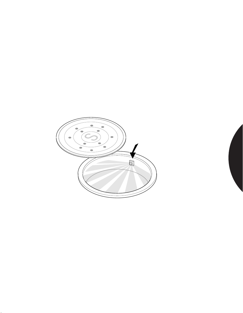
.........................................................................................................................................................................
Phone: 800.894.0412 - Fax: 888.723.4773 - Web: www.clrwtr.com - Email: [email protected]
Commercial & Industrial Applications
PROTECTING AGAINST ACCESS
THROUGH SEWERS
APPLICATION
Some sewers are large enough to permit the passage of humans. A PIR can be
used in a sewer to provide early detection of an intruder.
INSTALLATION
RECOMMENDED
PRODUCTS
The 6187CTX should be equipped with a standard lens for this application.
Use swivel bracket, if necessary, for mounting the PIR so that its curtain pattern
covers the sewer opening. After positioning for best coverage, tighten the bracket
in place and test the sensor.
6187CTX; 6083-N Swivel Bracket.
SPACE DETECTION
The 6187CTX comes in a cast aluminum gasket-sealed housing, protecting
it against snow, rain, dirt, etc. It is rated to operate to -40°C.
2.23
Page 47
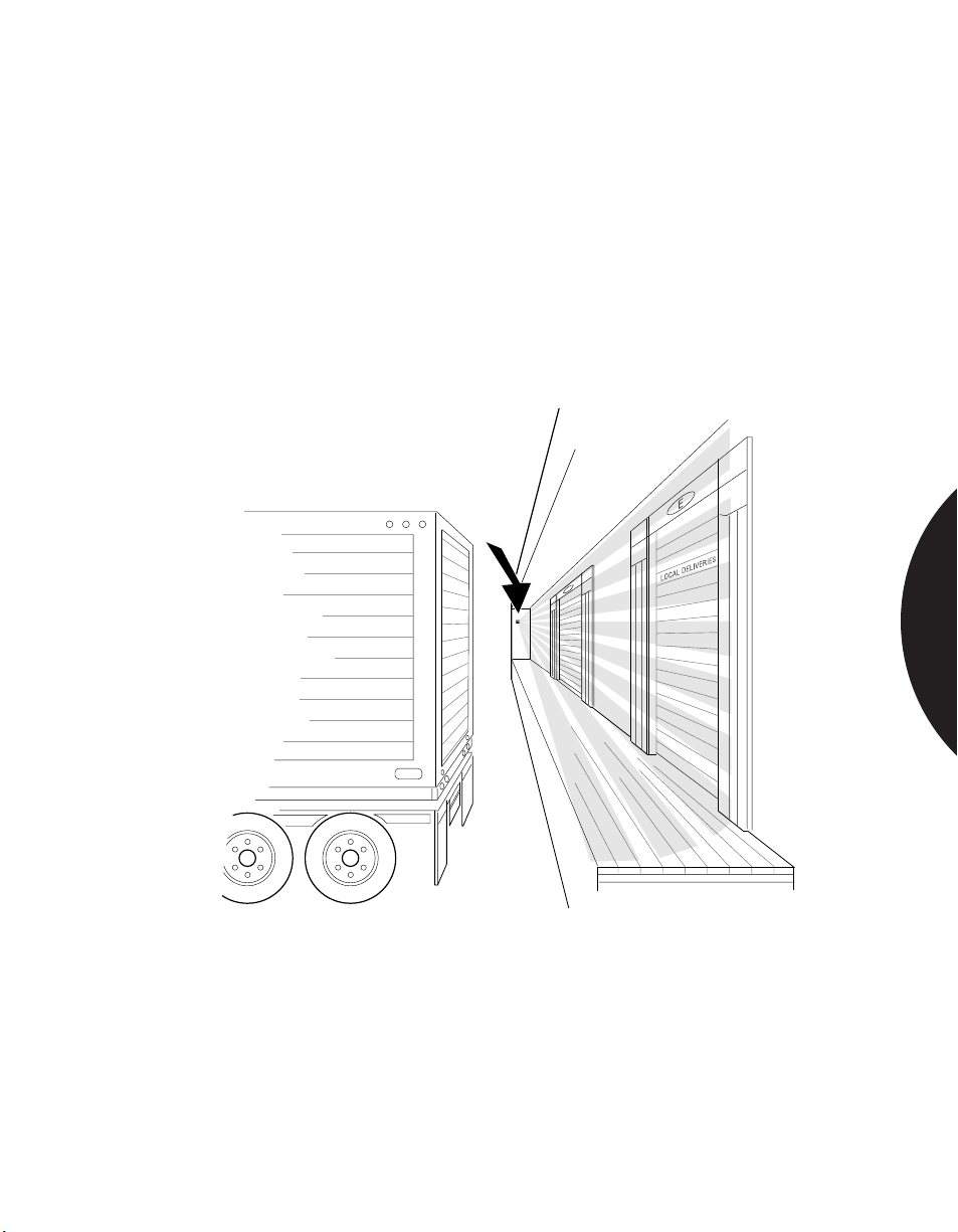
.........................................................................................................................................................................
Phone: 800.894.0412 - Fax: 888.723.4773 - Web: www.clrwtr.com - Email: [email protected]
Commercial & Industrial Applications
PROTECTING INTERIOR OF LOADING DOCKS
APPLICATION
INSTALLATION
RECOMMENDED
PRODUCTS
Loading docks are a frequent target of burglars. Early detection can avoid costly
break-ins to both the back of trucks and the warehouse itself. Sentrol’s 6187CTX
PIR is designed for outdoor use and can be directed to protect the targeted area
with the 6083-N swivel bracket.
Mount a 6187CTX on a 6083-N swivel bracket and direct the PIR toward the area
to be protected. Order unit with vertical barrier lens. Walk test the installation to
verify proper operation.
6187CTX; 6083-N Swivel Bracket.
SPACE DETECTION
The 6187CTX can be equipped with a vertical barrier lens. It comes in a cast
aluminum gasket-sealed housing, protecting it against “Mother Nature’s” elements
and is rated to -40°C.
2.24
Page 48
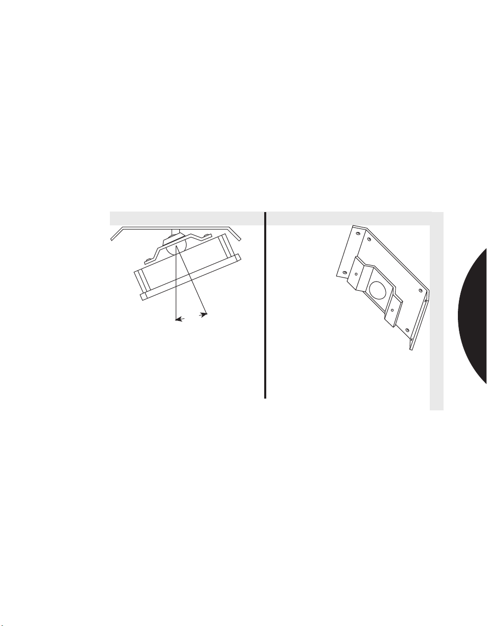
.........................................................................................................................................................................
Phone: 800.894.0412 - Fax: 888.723.4773 - Web: www.clrwtr.com - Email: [email protected]
Commercial & Industrial Applications
USING A SWIVEL BRACKET FOR AREAS WHERE
MOUNTING IS DIFFICULT
APPLICATION
The 6083-N swivel bracket can be used with the 6187CTX Outdoor PIR, the
6198 non-incendive and the 6197 Intrinsically Safe PIR in areas where mounting
is difficult.
INSTALLATION
RECOMMENDED
PRODUCTS
Remove back cover and use smaller self-tapping screws that ship with swivel
bracket. Can be either flat wall or corner mounted.
6083-N Swivel Bracket.
°
22.5
Flat Wall Corner
Top view
(max. adjusting angle 22.5°)
SPACE DETECTION
2.25
Page 49
.........................................................................................................................................................................
Phone: 800.894.0412 - Fax: 888.723.4773 - Web: www.clrwtr.com - Email: [email protected]
Commercial & Industrial Applications
EXTREME CONDITIONS
APPLICATION
INSTALLATION
RECOMMENDED
PRODUCTS
Meat lockers, unregulated buildings in very hot or cold climates, and other areas of
extreme temperature often require space protection.
Refer to Protecting Vacation Homes and Garages in the Residential Applications
for installation instructions.
For industrial applications in very cold
environments, Sentrol manufactures the
6187CTX PIR. It operates down to
-40°C (-40°F). The 6155CT can also
be used in cold climates, but is housed in
standard plastic.
For very hot environments where the
temperature differential between a
person and the surrounding air is very
small, Sentrol offers the Sharpshooter
6155XT, which can distinguish
temperature differences as small as 1°C.
Sunlight—Avoid direct sunlight on the
plastic lens (even with UV stable plastics).
Temperature—The 6187CTX PIR is rated to perform from -40°F (40°C) to
+120°F (+50°C). Be aware of a temperature in excess of these specifications.
SPACE DETECTION
Humidity/Rain/Fog—Make sure the conduit openings are well sealed and the
mounting holes are sealed.
Birds & Animals—Depending on the size, speed and proximity to the detector,
warm blooded animals can trigger an alarm. The larger the animal, the further away
it can be detected. Mount the PIR high-at least 7 ft. (2.13m)-on a flat surface that
discourages rodents or birds from perching. Avoid directing the sensor towards
bushes or branches where birds could perch. You may consider mounting two PIRs,
one above the other, in parallel to require verification of alarm.
Weeds & Bushes—Tree branches or bushes can cause an alarm when the wind
moves them, and weeds and bushes can block detection. Keep branches and bushes
at least 30 feet (9.15m) from the PIR.
Install the PIR away from vines or vegetation that could block the view.
Testing your installation over a 24-hour period can help troubleshoot any false alarm
sources. Take the time to know your environment. Up front planning is always less
expensive than unwanted alarms later.
2.26
Page 50
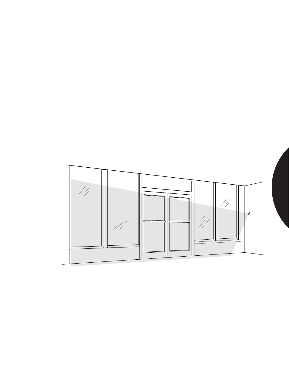
.........................................................................................................................................................................
Phone: 800.894.0412 - Fax: 888.723.4773 - Web: www.clrwtr.com - Email: [email protected]
Commercial & Industrial Applications
STORE FRONT APPLICATIONS
APPLICATION
INSTALLATION
RECOMMENDED
PRODUCTS
A curtain PIR such as the AP425 often provides a cost-effective and secure means
of detecting intrusion through large windows and doors such as are typically found
in a store-front or car showroom.
Mount the sensor 3 feet from the window. This avoids any possibility that one half
of the curtain is “looking” at the window, while the other half is not, a potential
cause of instability. If this is not possible, angle the sensor slightly inwards.
Install the appropriate mirror mask(s). In the drawing below, the left side of the
pattern is masked out (always mask out curtains which are directed at the
window), while the right side is left active to protect the inside of the store and
provide convenient walk testing.
Make sure the sensor is programmed for standard sensitivity and that the
appropriate range setting is programmed.
AP425
SPACE DETECTION
The AP425 can provide true curtain coverage for areas
requiring vertical barrier detection, like store fronts.
2.27
Page 51
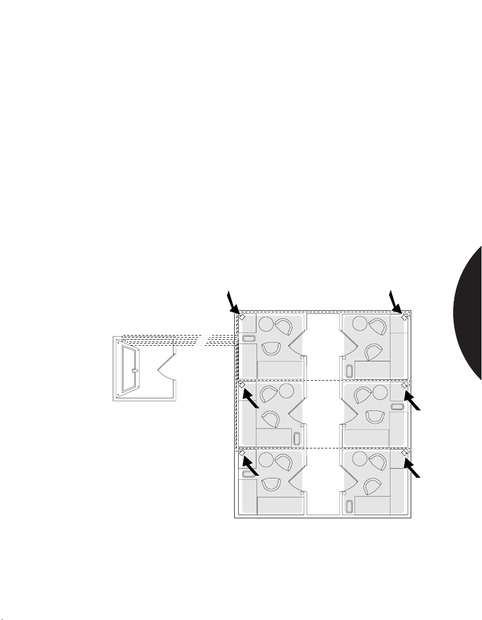
.........................................................................................................................................................................
Phone: 800.894.0412 - Fax: 888.723.4773 - Web: www.clrwtr.com - Email: [email protected]
Commercial & Industrial Applications
REMOTE TEST APPLICATION
APPLICATION
INSTALLATION
RECOMMENDED
PRODUCTS
Many organizations require daily or weekly operational testing of all PIRs.
For large industrial or government installations, maintenance costs are increased
when these tests must be performed manually. With Sentrol’s remote test option
your customers can reduce maintenance costs by testing each PIR remotely,
from a central control panel.
Sentrol’s remote test option has been accepted for use by the Department of
Defense, Defense Intelligence Agency, General Services Administration, and
Department of Energy.
Select the application specific Sentrol 6000 Series Passive Infrared (PIR) unit with
the remote test feature. Provide adequate number of wires for basic PIR power
and alarm status operation. Provide an additional 2 wires (usually 22 AWG) for
carrying 12 V to 18 VDC. Connect the remote test wires from your control panel to
the PIR remote test loop. Activate the remote test switch at the control panel by
following the remote test option circuit instructions provided with unit.
All Sentrol 6000 Series units (except 6197 & 6198).
PIR 1
PIR 6
PIR 2
PIR 3
SPACE DETECTION
Control
Control Room
Room
PIR 5
From Control Room activate
specific PIR remote test power
switch to test specific PIR in
selected room.
Building Complex
PIR 4
2.28
Page 52
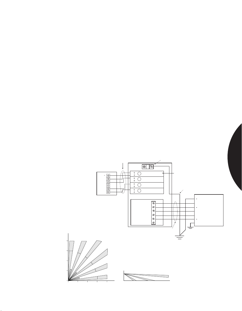
.........................................................................................................................................................................
Phone: 800.894.0412 - Fax: 888.723.4773 - Web: www.clrwtr.com - Email: [email protected]
Industrial Applications
EXPLOSIVE ATMOSPHERES
APPLICATION
Areas such as munitions depots, grain storage areas, and chemical plants can often
involve explosive atmospheres. It is imperative, therefore, that PIRs used in such
areas contribute no electrical signal or field that could cause ignition.
INSTALLATION
Mount the 6197 Intrinsically Safe PIR in the hazardous area using either a sealed
cable or sealed conduit fitting. Replace the standard lens with either of the other
two lenses if needed.
Mount the Barrier Box in the non-hazardous area next to the alarm panel.
Run wire between the Barrier Box and the alarm panel terminals. Connect the
ground lug on the bus bar inside the Barrier Box to an intrinsically safe ground
using a 12 AWG wire or larger. Connect the chassis ground on the alarm panel to
earth ground.
Remove the front housing and install the jumpers in the PIR in the walk test
mode. Select either one or two zone mode. Replace the front housing with the
rubber gasket using four screws. Walk test the PIR. Install the Barrier Box lid.
The Sentrol 6197 Intrinsically Safe PIR System is FM-approved and UL Listed
RECOMMENDED
PRODUCTS
for use in hazardous locations. For non-explosive applications that still require
class I, Division 2, Groups A, B, C & D use the 6198 Non-incendive PIR.
6197 PIR
TAMP
Standard Lens Coverage
40'
12.2m
30'
9.1m
20'
6.1m
10'
3.0m
0
Top View
0 10' 20' 30’ 40'
3.0m 6.1m 9.1m 12.2m
COM
Cable or
Conduit
6197BB (Barrier Box)
3
1
4
+
NC
3
2
4
3
3
4
3
4
4
Switching Module
+12V
TAMP
TAMP
COM
Side View
7'
2.1m
0
30 ° 15° Floor Line
Ground Lug
Barriers
12 AWG or larger
NC
NO
Cable or
Conduit
Intrinsically Safe
Ground
Earth
Ground
+
+
+
CHASSIS
Alarm Panel
SUPPLY (RETURN)
SUPPLY (+12V NOM)
TAMPER LOOP
TAMPER LOOP
ALARM LOOP
ALARM LOOP
4°
Additonal coverage patterns include vertical barrier and long range.
SPACE DETECTION
2.29
Page 53
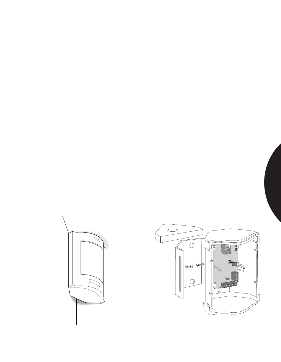
.........................................................................................................................................................................
Phone: 800.894.0412 - Fax: 888.723.4773 - Web: www.clrwtr.com - Email: [email protected]
Residential Applications
WHEN APPEARANCE IS PARAMOUNT
APPLICATION
INSTALLATION
RECOMMENDED
PRODUCTS
When adding a security system to an existing residence, the appearance of the
system is often paramount in the mind of the homeowner. The homeowner will be
concerned with sensor placement, the location of wires, location of the control
panel, and how holes are drilled through existing walls.
A unit that mounts close to the ceiling and in a corner is the least noticeable. It is
also the most effective because it allows you to use a standard 90° lens, which
gives you entire room coverage.
• Choose a corner that is adjacent to the room’s entrance to get the best line of
sight for the sensor. This is also the least obtrusive location.
• Using the 6351 Sharpshooter DL, you will be able to mount as close to the
ceiling as possible, making the unit even less noticeable. Pulling wires through
the ceiling can be much easier and quicker than pulling them through walls.
• Using the foam spacer, mount the bracket to the wall and connect the wires to
the unit’s terminal block (see illustration). Then snap the cover in place.
• Most rooms need only one-zone sensitivity. If the room is subject to
temperature fluctuations or other instability, adjust the unit for two-zone
sensitivity.
• The DL incorporates an adjustable circuit board that allows you to mount flush
to ceiling from 7' to 11' high.
• Walk-test the unit to ensure correct operation.
The DL 6351 DesignLine PIR combines an attractive, unobtrusive design with an
easy-to-mount snap-on bracket. It can be mounted in a corner within 1/8" (3 mm)
of the ceiling which makes it easier to install, saving you time and money.
SPACE DETECTION
The 6351 DesignLine fits within 1/8”
of the ceiling from 7 to11 feet high.
Using the corner tool and bracket saves
installation time.
2.30
Page 54
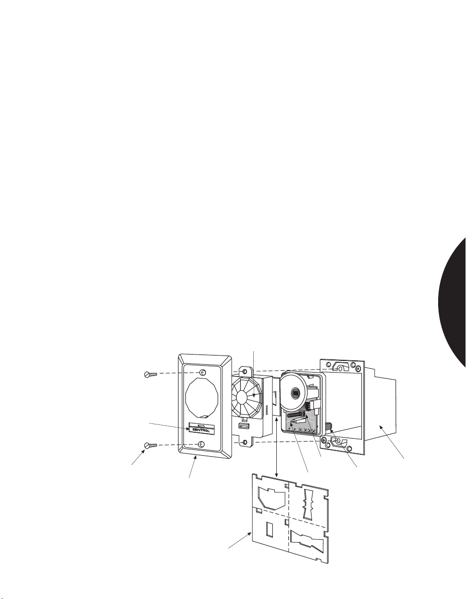
.........................................................................................................................................................................
Phone: 800.894.0412 - Fax: 888.723.4773 - Web: www.clrwtr.com - Email: [email protected]
Residential Applications
FLUSH-MOUNTING A PIR
APPLICATION
INSTALLATION
RECOMMENDED
PRODUCTS
Flush-mounting a PIR makes the sensor no more intrusive in a room than an
electrical outlet or switch. Flush mount PIRs are most often used in pre-wired
security installations, but can also be used in retro-fit installations.
The 6255FM Flush mount PIR fits into a standard, plastic single-gang electrical
box. If the security system is to be pre-wired, mount a single-gang box for each
sensor as planned with the builder. Sensor wires can then be easily run through
walls and routed to the control panel. Do not run the PIR wires along side AC
wires due to noise problems.
Choose a wall that is adjacent to the room’s entrance to get the best line of sight
for the sensor. Or, when using the 6255FM, mount the box in the ceiling.
Run wires through the box to the sensor’s terminal block. Most rooms need only
one-zone sensitivity. If the room is subject to temperature fluctuations or other
instability, use the 6155 and adjust the unit for two-zone sensitivity.
Screw the entire unit into the single-gang box as you would an electrical outlet.
For retro-fit installations, take care to cut a hole in the wall just large enough to fit
a single-gang remodel box. Or, in the case of the 6155, cut the hole just large
enough for the PIR to fit. If the hole is too large, the flush mount PIR’s cover plate will
not cover it completely.
Walk-test the unit to ensure correct operation.
The 6255FM Flush Mount SureShot, and the 6155 Sharpshooter with the 6082
Flush Mount Kit, can be mounted in the wall or ceiling.
Lens
SPACE DETECTION
PET
ALLEY
Sliding LED cover
Mounting screws
Flush mount cover plate
®
Masking kit
WIDE
ANGLE
SPOT
Tamper switch
(6257FM only)
LED
V
E
R
T
I
C
A
L
PET
ALLEY
Terminal block
B
A
R
R
I
E
R
Exploded view of the 6255 Flush Mount PIR
Single gang box
(not included)
2.31
Page 55
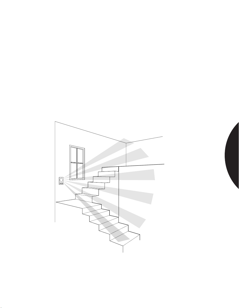
.........................................................................................................................................................................
Phone: 800.894.0412 - Fax: 888.723.4773 - Web: www.clrwtr.com - Email: [email protected]
Residential Applications
PROTECTING MULTILEVEL HOMES
APPLICATION
INSTALLATION
RECOMMENDED
PRODUCTS
In today’s homes with multi-level flooring, care must be taken to ensure complete
coverage. The most cost-effective way to obtain complete coverage is to use a PIR
with a 360° lens wall- or ceiling-mounted. A standard, wall-mounted 90° lens may
leave creep zones that an intruder can use to invade a home.
Choose a wall that is adjacent to the room’s entrance to get the best line of sight
for the sensor. Or, mount the sensor in the ceiling to achieve 360° coverage of
the room.
Walk-test the unit to ensure correct operation. Verify that there are no creep zones.
The 6255 SureShot, or the 6255FM Flush Mount SureShot, can be wall or
ceiling mounted.
SPACE DETECTION
The 6255FM in a stairwell application.
2.32
Page 56
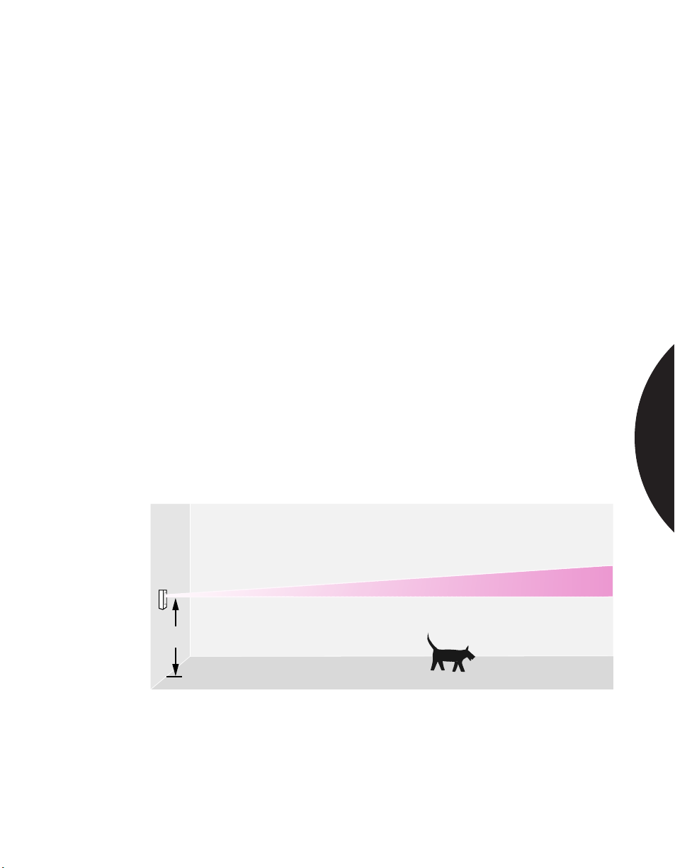
.........................................................................................................................................................................
Phone: 800.894.0412 - Fax: 888.723.4773 - Web: www.clrwtr.com - Email: [email protected]
Residential Applications
CREATING A PET ALLEY
APPLICATION
INSTALLATION
RECOMMENDED
PRODUCTS
Because PIRs are sensitive to moving, heat-radiating sources, they can be
triggered by animals as well as humans. To avoid this false alarm hazard, the
coverage pattern of the PIR must be aimed so it does not extend to areas where
pets can move around in the home when the system is on.
A PIR with a pet alley lens must be mounted at a specific height on the wall to
avoid areas where a pet may climb or jump. The Sharpshooter Installation Mirror
is especially useful in setting up a pet alley quickly, without the hassle of timeconsuming measurements. Mounting the unit against the wall at the desired
height, center the reflection of your eye in the bulls-eye at the bottom of the
mirror and look for tables, chairs and other objects on which a pet could jump.
Adjust the unit or move the object so those areas are avoided. Remember that the
size of the pet should also be considered during your aiming and re-adjustment. If
necessary, mask off high traffic areas for pets (such as cat climbing posts) with the
masking kit included with each Sentrol PIR.
Remind the homeowner that furniture moved into the coverage pattern of the PIR
can give a pet a place to climb or jump — resulting in false alarms.
Walk-test the unit to ensure correct operation.
The 6255 SureShot, 6255FM Flush Mount SureShot, 6351 DesignLine, or 6155
Sharpshooter can all be used to create pet alleys. Use the 6074 pet alley lens and
the 6060 mirror sighting system with the 6155 Sharpshooter.
SPACE DETECTION
3'3"
The 6255FM is very popular in this pet alley application
since it sits flush to the wall, providing an unobtrusive,
attractive alternative.
2.33
Page 57
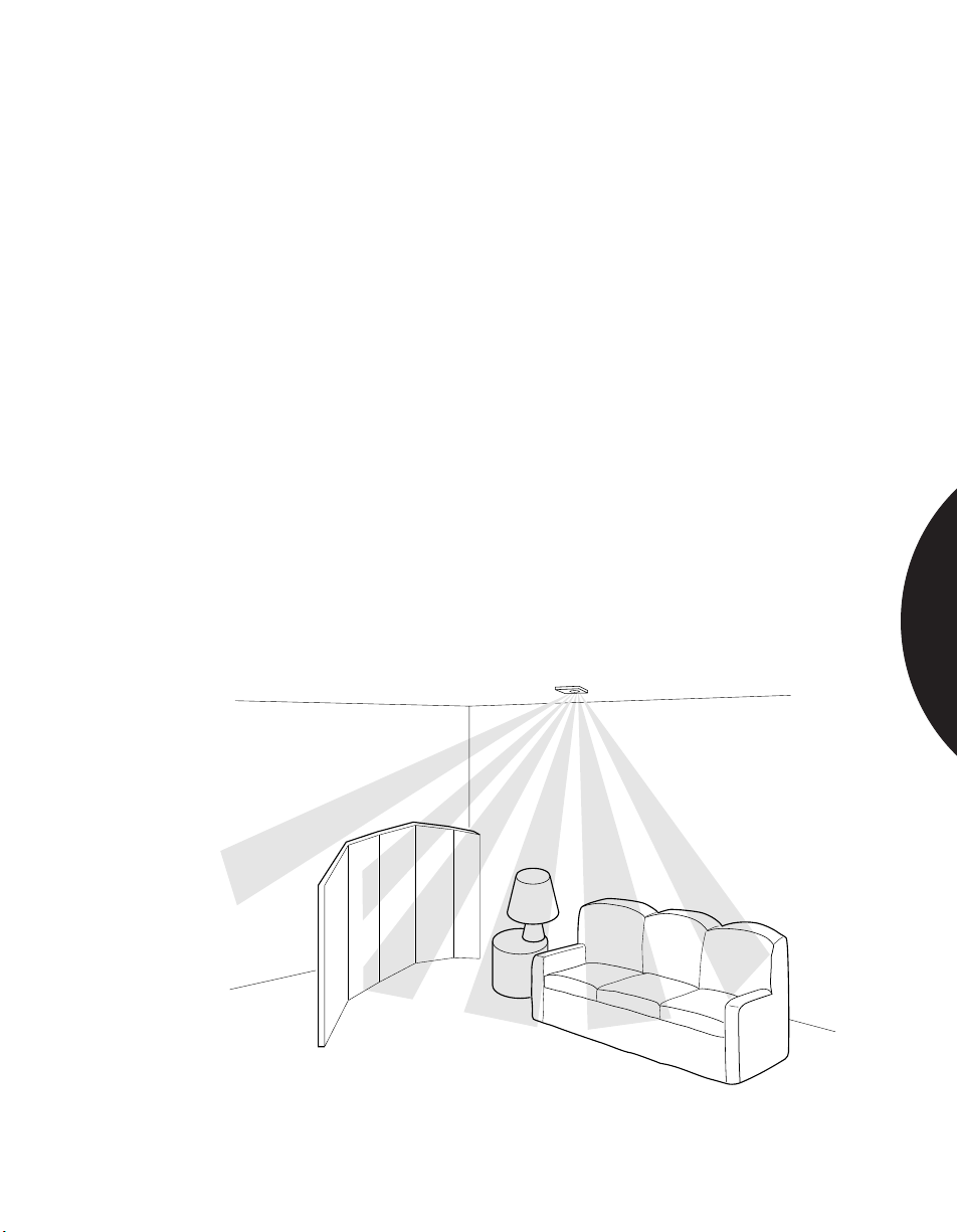
.........................................................................................................................................................................
Phone: 800.894.0412 - Fax: 888.723.4773 - Web: www.clrwtr.com - Email: [email protected]
Residential Applications
MOUNTING A PIR IN THE CEILING
APPLICATION
INSTALLATION
RECOMMENDED
PRODUCTS
Mounting a PIR in the ceiling is an excellent way to hide wiring in single-level
homes. Running wires in an attic for ceiling mounted sensors allows you to easily
avoid water supply pipes, drain-waste-vent pipes, heating and cooling duct work,
venting duct work for kitchens and bathrooms, and high voltage wiring. It is also
useful for providing complete coverage of rooms with obstructions such as halfwalls and shelving that can block coverage.
The Sentrol SureShot PIR and low profile Aritech PR361 provides 360° coverage
when mounted in the ceiling. For flush mount installation, install a standard
plastic single-gang outlet box. A remodel box can be used for homes where
construction is already complete.
Connect the wires to the terminal block of the sensor and screw the sensor and
cover plate into the box as you would an electrical outlet.
For ceiling mounting, drill a hole through the ceiling in the desired location and
pull the wire through. Punch out the wiring knockout in the back cover and pull
the wire through the hole. Attach the back cover to the ceiling using appropriate
mounting knockouts. Snap the circuit board and front cover into the back cover.
Walk-test the unit to ensure correct operation.
The 6255 SureShot, the 6255FM Flush Mount SureShot, and the PR361 can be
ceiling mounted.
SPACE DETECTION
Ceiling mount PIRs like the 6255 and PR361 help to eliminate obstacles in a room.
2.34
Page 58
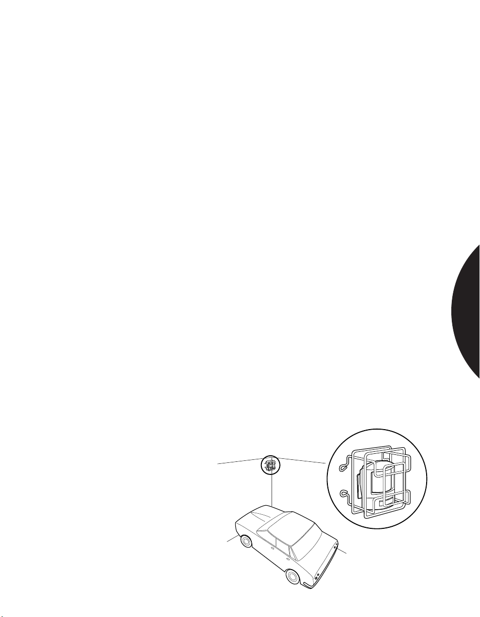
.........................................................................................................................................................................
Phone: 800.894.0412 - Fax: 888.723.4773 - Web: www.clrwtr.com - Email: [email protected]
Residential Applications
PROTECTING VACATION HOMES AND GARAGES
APPLICATION
INSTALLATION
RECOMMENDED
PRODUCTS
Garages and vacation homes often contain valuable objects that can be protected
with a PIR. Such spaces present a unique challenge because they are not
temperature-regulated on a regular basis. In garages, there can also be a greater
risk of damage from accidental impacts with balls, tools, lumber, etc. Garages and
vacation homes can also contain rodents.
The Sentrol line of space protection devices includes PIRs that operate in a very
wide range of temperatures. The 6155CT Sharpshooter, for example, operates
from -40°C to +50°C (-40°F to +120°F). It is ideal for use in extremely cold
climates. The 6155XT Sharpshooter offers 1°C discrimination capabilities, making
it ideal for very warm climates where the temperature difference between the
background and the intruder may be very small. Quad element pyros improve a
PIR’s ability to differentiate rodents from intruders.
An optional wire cage can be fit over either the 6155CT or XT to prevent
accidental breakage and vandalism.
For best installation, use the Sharpshooter’s mirror sighting system (model 6060).
The mirror gives you a true picture of potential false alarm sources and helps you
achieve the best mounting location for maximum detection. The Sharpshooter s
swivel bracket allows easy aiming and adjusting.
Attach the back case to the swivel bracket. Adjust the mounting angle by
loosening the screw on the ball joint shoe and positioning the case. When desired
coverage is achieved, tighten the ball joint shoe screw. Snap on the front cover
with the desired lens installed. Attach the protective wire cage.
Position the sensor so that it will not be subject to early morning or late evening
light entering through windows. Also, do not aim the sensor at mirrors that may
direct such light onto the detector. The mirror sighting system will help you
achieve the best coverage.
Walk-test the unit to ensure correct operation.
The 6155CT and XT Sharpshooters are the best PIRs for this application.
SPACE DETECTION
The 6155CT provides
protection in areas where
the temperatures are below
freezing. The (6085) wire
cage is a useful accessory
in garages, warehouses or
gymnasiums.
2.35
Page 59
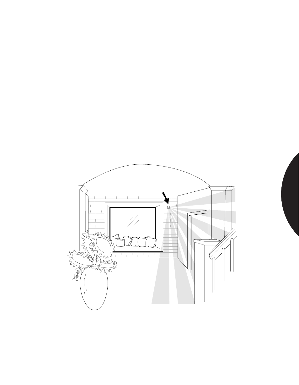
.........................................................................................................................................................................
Phone: 800.894.0412 - Fax: 888.723.4773 - Web: www.clrwtr.com - Email: [email protected]
Residential Applications
PROTECTING AREAS WITH WIRELESS SENSORS
APPLICATION
INSTALLATION
RECOMMENDED
PRODUCTS
Wireless PIRs can be used in residential and commercial applications. Wireless
units are especially useful for installations where it is difficult or impossible to
run wires.
The Sentrol 616503 and 616509 Wireless Sharpshooter PIRs are compatible with
virtually all wireless transmitters.
Wherever possible use a single PIR to cover more than one room. Mount the
wireless back box and then insert the transmitter for the sensor. Attach the PIR to
the swivel bracket that is incorporated into the front cover of the back box. Use
the sighting mirror to locate the coverage pattern that corresponds with the lens
you will use.
Walk-test the installation to ensure correct operation.
616503 3-Volt Wireless Sharpshooter PIR;
616509 9-Volt Wireless Sharpshooter PIR
SPACE DETECTION
2.36
Page 60
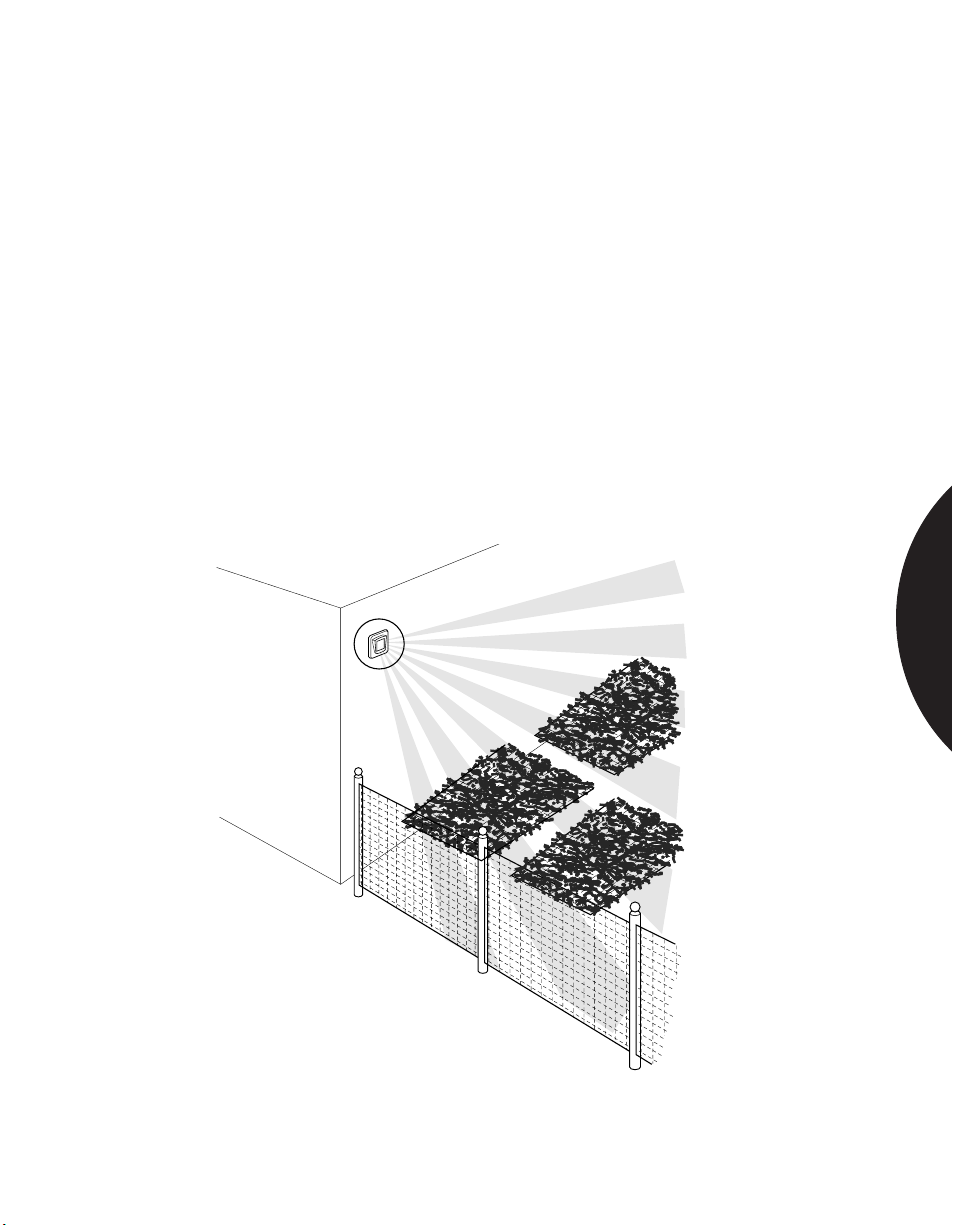
.........................................................................................................................................................................
Phone: 800.894.0412 - Fax: 888.723.4773 - Web: www.clrwtr.com - Email: [email protected]
Residential Applications
PROTECTING A VEGETABLE GARDEN
APPLICATION
INSTALLATION
RECOMMENDED
PRODUCTS
A PIR can be used to sound a local alarm when animals enter a vegetable garden.
The 6187CTX Outdoor PIR is excellent for this application. It can be equipped
with a curtain lens and mounted on all four sides of a garden to provide complete
perimeter detection. The PIRs are NOT, however, substitutes for a good fence.
Mount one PIR at each corner of the garden area approximately 7 ft. (2.13m) high.
Avoid direct sunlight on the plastic lens.
Keep away from branches that may impede PIR’s coverage pattern.
Make sure conduit openings and mounting holes are well sealed. If conduit is
used, run the conduit out the side or bottom of the unit to keep condensation from
the conduit from draining into the PIR’s housing.
The cast metal housing of the 6187CTX is specifically designed for outdoor
applications. It provides water resistance and reliable detection in temperatures
from -40°C to +50°C (-40°F to +120°F).
SPACE DETECTION
The 6187CTX can be used to
protect outdoor commercial areas.
2.37
Page 61
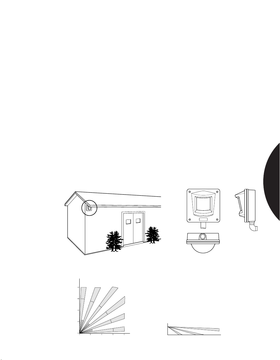
.........................................................................................................................................................................
Phone: 800.894.0412 - Fax: 888.723.4773 - Web: www.clrwtr.com - Email: [email protected]
Residential & Commercial Applications
PROTECTING OUTDOOR SPACES
APPLICATION
INSTALLATION
RECOMMENDED
PRODUCTS
There are many applications for motion detection outdoors. Most of them stem
from the need to protect property that is at risk. There are also occasions to set up
a pre-entry barrier to detect unwanted intruders — whether human or animal.
Sentrol has developed a rugged passive infrared detector that is excellent for
outdoor use. The 6187CTX Outdoor PIR combines an advanced signal processing
circuit, custom pyro and lens with a cast metal housing that is water resistant, dust
and shock proof. It is rated to perform in temperatures from -40°C to +50°C (-40°F
to +120°F).
Carefully consider if central station monitoring if necessary. A local alarm or local
response such as CCTV may be appropriate if the potential for false alarms is high.
Mount the PIR high — at least 7' (2.13m) — on a flat surface to discourage rodents
or birds from perching.
Make sure conduit openings and mounting holes are well sealed. If conduit is
used, run the conduit out the side or bottom of the unit to keep condensation from
the conduit from draining into the PIR’s housing.
Avoid direct sunlight on the plastic lens.
Keep away from branches that may impede PIR’s coverage pattern.
Use the 6187CTX for outdoor applications.
SENTROL
SPACE DETECTION
The Industrial 6187CTX can be installed outdoors
as well as indoors and is rated down to -40°F.
40'
12.2m
30'
9.1m
20'
6.1m
10'
3.0m
0
Top View
0 10' 20' 30' 40'
3.0m 6.1m 9.1m 12.2m
2.1m
7'
The 6187CTX is fully sealed from
water, dust and dirt.
Side view
4°
30° 15° Floor line
2.38
Page 62
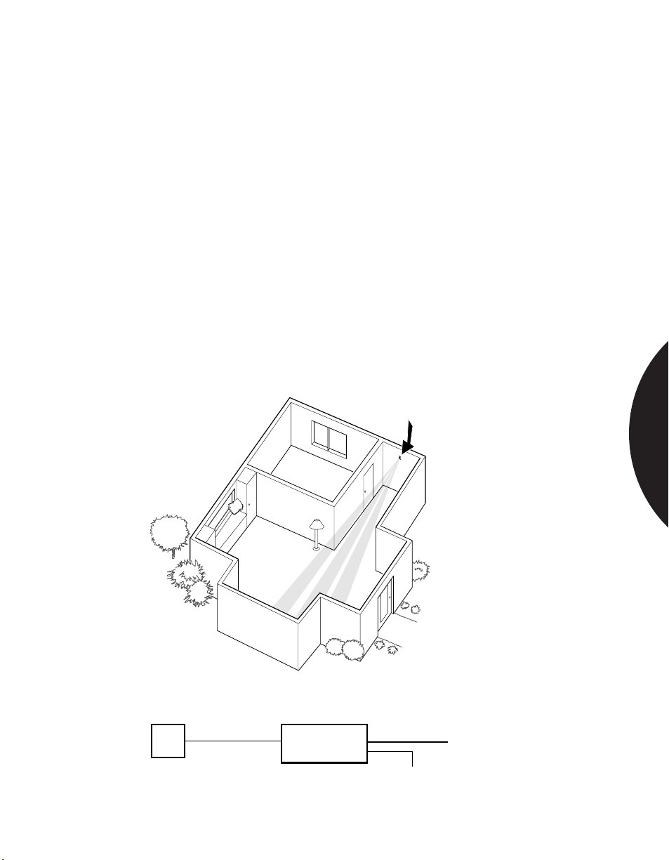
.........................................................................................................................................................................
Phone: 800.894.0412 - Fax: 888.723.4773 - Web: www.clrwtr.com - Email: [email protected]
Residential & Commercial Applications
USING A PIR TO PROTECT HALLWAYS OR
ACTIVAGE HALLWAY AND LOBBY LIGHTING
APPLICATION
INSTALLATION
RECOMMENDED
PRODUCTS
A PIR with a single-spot or vertical barrier coverage pattern can be used to protect
long narrow areas such as corridors or hallways.
A PIR can also be used to activate lighting controls in hallways and lobbies.
Such applications are particularly useful when it is not possible to mount light
switches near entrance doors.
A single-spot or vertical barrier PIR should be mounted at the opposite end of a
hallway or lobby from its entrance. Anyone entering the hallway from the entrance
or from side doors will be detected.
A separate relay with power supply must be used to control lights.
Walk-test the installation to ensure correct operation.
The AP125, AP425 and 6255 SureShot with a single spot or vertical barrier mask,
the 6155 Sharpshooter with a long range (6071) or curtain (6073) lens, and the 6351
DesignLine with a vertical barrier mask will all work in this application. Things to
consider when selecting a PIR are: length of the hallway, range of the PIR,
appearance of the PIR, and pets.
SPACE DETECTION
Several Sentrol/Aritech products can be
used to obtain coverage pattern desired.
PIR
When activating lights use a separate relay and power supply.
Relay
&
Power Supply
120 VAC
To Lights
2.39
Page 63
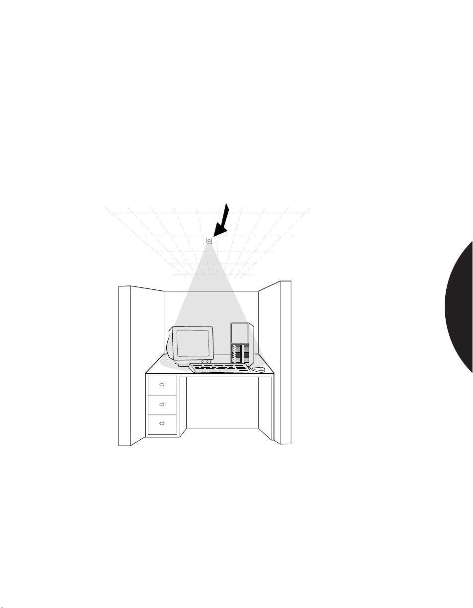
.........................................................................................................................................................................
Phone: 800.894.0412 - Fax: 888.723.4773 - Web: www.clrwtr.com - Email: [email protected]
Residential & Commercial Applications
PROTECTING VALUABLE EQUIPMENT
APPLICATION
INSTALLATION
RECOMMENDED
PRODUCTS
A PIR with a single spot mask can be mounted in the ceiling above valuable
equipment such as computers, TVs, video equipment, etc.
A single-spot PIR should be mounted in the ceiling, directly above the equipment
to be protected.
Walk-test through the PIRs field of view to test for proper operation.
The 6255 SureShot and 6255FM SureShot with a single spot mask or AP425
curtain PIR. Verify that range of PIR is suitable for application.
SPACE DETECTION
Often times a very narrow coverage pattern is needed to
protect expensive equipment. Use 6255/6255FM for
ceiling mount or AP425 for wall mount.
2.40
Page 64
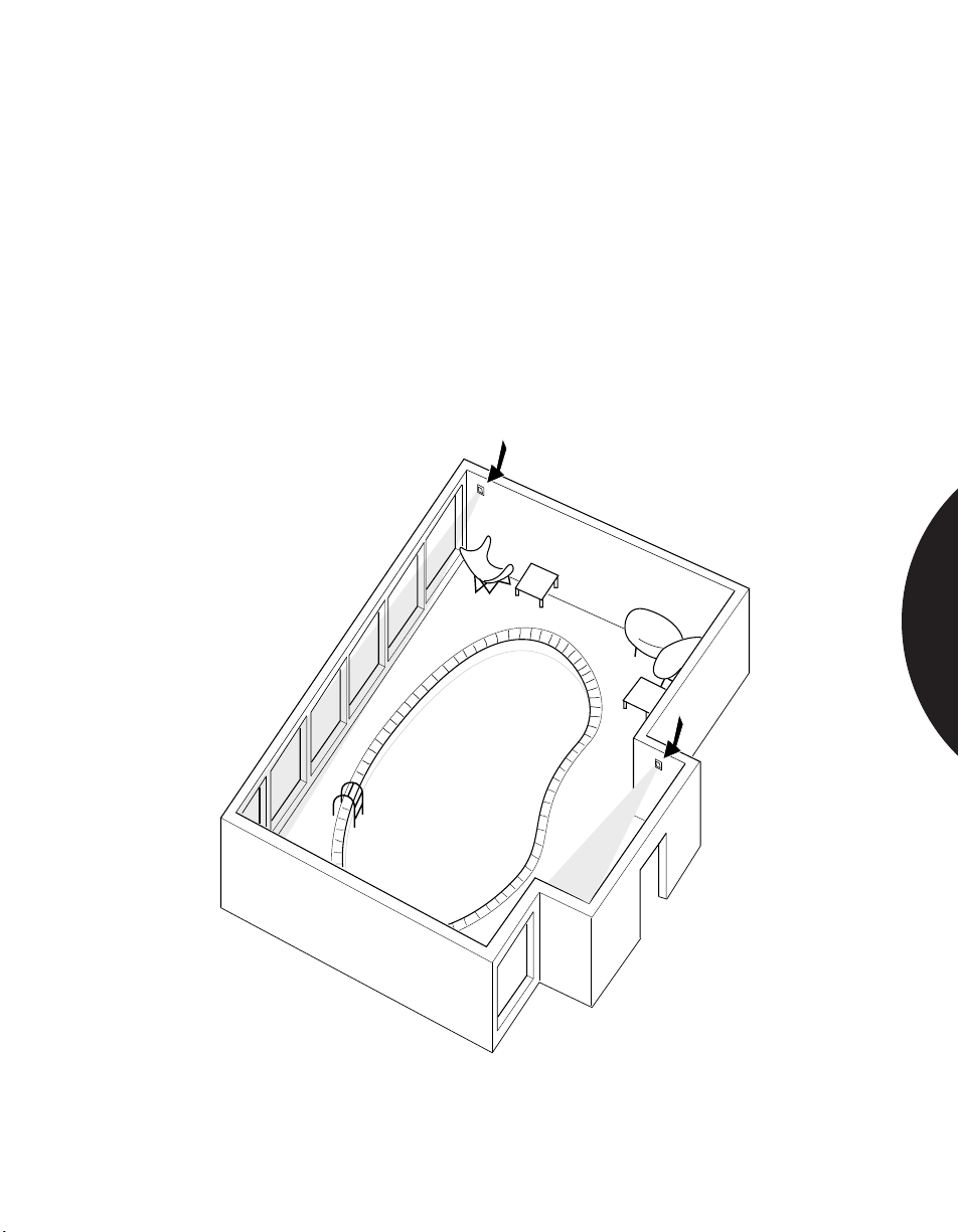
.........................................................................................................................................................................
Phone: 800.894.0412 - Fax: 888.723.4773 - Web: www.clrwtr.com - Email: [email protected]
Residential & Commercial Applications
PROTECTING INDOOR SWIMMING POOLS
APPLICATION
INSTALLATION
RECOMMENDED
PRODUCTS
A PIR can be used to sound a local alarm upon unauthorized entrance into indoor
swimming areas either at home or in a hotel after hours.
Mount the PIR on the wall above the entrance door, pointing downward; or in the
ceiling pointing toward the door.
Mount the PIR approximately 7 ft. (2.13m) high.
Make sure conduit openings and mounting holes are well sealed. If conduit is
used, run the conduit out the side or bottom of the unit to keep condensation from
the conduit from draining into the PIR’s housing.
The cast metal housing of the 6187CTX provides water resistance in humid indoor
swimming environments.
SPACE DETECTION
The 6187CTX comes in a cast
aluminum gasket-sealed housing
to keep out moisture and resist
corrosion.
2.41
Page 65
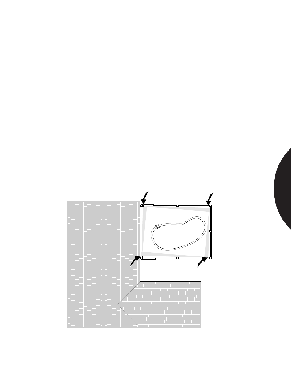
.........................................................................................................................................................................
Phone: 800.894.0412 - Fax: 888.723.4773 - Web: www.clrwtr.com - Email: [email protected]
Residential & Commercial Applications
PROTECTING OUTDOOR SWIMMING POOLS
APPLICATION
INSTALLATION
RECOMMENDED
PRODUCTS
A PIR can be used to sound a local alarm upon unauthorized entrance into outdoor
swimming areas. A local alarm can notify a parent when young children enter a
restricted pool area.
The 6187CTX Outdoor PIR is excellent for this application. It can be equipped
with a curtain lens and mounted on all four sides of a swimming pool to provide
complete perimeter detection.
NOTE: The PIRs in this application DO NOT take the place of a fence. All
outdoor swimming pools should be surrounded by a fence for liability reasons.
Mount one PIR at each corner of the pool area approximately 7 ft. (2.13m) high.
Avoid direct sunlight on the plastic lens.
Keep away from branches that may impede PIR’s coverage pattern.
Make sure conduit openings and mounting holes are well sealed. If conduit is
used, run the conduit out the side or bottom of the unit to keep condensation from
the conduit from draining into the PIR’s housing.
The cast metal housing of the 6187CTX is specifically designed for outdoor
applications. It provides water resistance and reliable detection in temperatures
from -40°C to +50°C (-40°F to +120°F).
SPACE DETECTION
The 6187CTX comes in a cast aluminum housing that
is gasket sealed to resist corrosion and is rated to -40°C.
2.42
Page 66
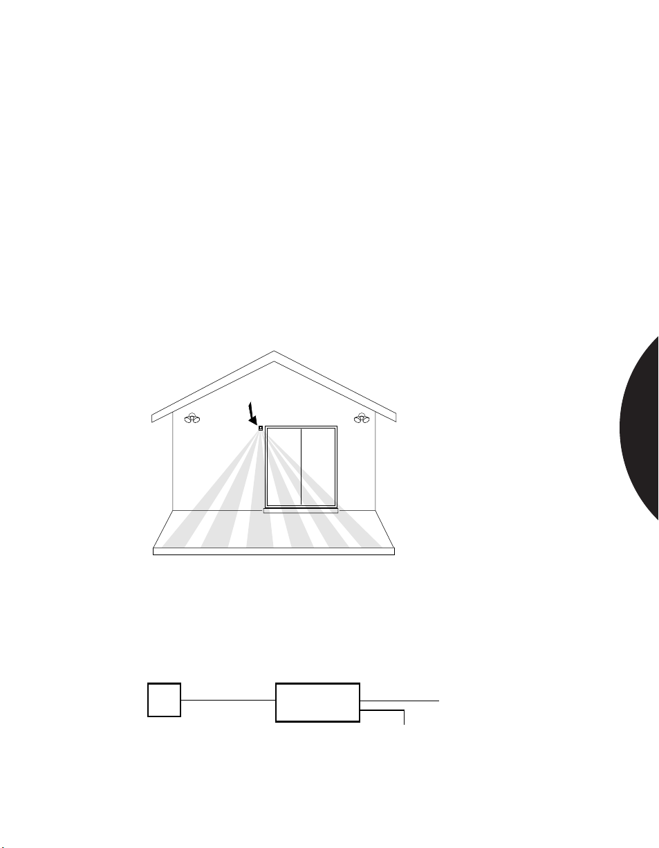
.........................................................................................................................................................................
Phone: 800.894.0412 - Fax: 888.723.4773 - Web: www.clrwtr.com - Email: [email protected]
Residential & Commercial Applications
USING A PIR TO ACTIVATE OUTDOOR LIGHTING
APPLICATION
INSTALLATION
RECOMMENDED
PRODUCTS
A PIR can be used to activate lighting controls around homes, detached garages,
gardens, back yard patios and decks, outdoor parking lots, auto dealerships,
shopping areas, shipping areas, garden shops, aircraft hangers, perimeters of
military installations, and public utility installations.
Mount the PIR approximately 7 ft. (2.13m) high on a flat surface to discourage
rodents or birds from perching.
Make sure conduit openings and mounting holes are well sealed. If conduit is
used, run the conduit out the side or bottom of the unit to keep condensation from
the conduit from draining into the PIR’s housing.
Avoid direct sunlight on the plastic lens.
Keep away from branches that may impede PIR’s coverage pattern.
6187CTX Outdoor PIR
SPACE DETECTION
The 6187CTX comes in a cast aluminum gasket-sealed
housing that is water resistant and operates to -40°C.
PIR
When activating lights use a separate relay and power supply.
Relay
&
Power Supply
120 VAC
To Lights
2.43
Page 67

.........................................................................................................................................................................
Phone: 800.894.0412 - Fax: 888.723.4773 - Web: www.clrwtr.com - Email: [email protected]
Introduction
MAGNETIC CONTACTS
Sentrol has earned its leadership position in the manufacture of magnetic contact
sensors by pioneering advances such as the use of multiple reeds, “wide gapping”
and numerous features that reduce false alarms. We have developed a range of
innovative designs to assure both greater sensitivity and complete reliability, even
in the most demanding environments. With over 400 models to chose from, we
offer the most comprehensive line of magnetic contacts and peripherals available.
Built for durability and dependability, Sentrol magnetic contacts are conservatively
rated at 10,000,000 cycles, ensuring long life. Every reed connection is hand
soldered and the reeds in many models are environmentally sealed. Our magnetic
contacts are tested before they leave the factory — 100% of the time.
Our world class manufacturing standards and attention to detail virtually eliminate
all out-of-box failures. You can install Sentrol magnetic contacts quickly and with
every confidence in their reliability.
Many residential and commercial applications for magnetic contacts are similar.
Residential users, however, will typically be more concerned with appearance than
commercial users. Commercial considerations include specific issues such as how
to protect valuables in storefront windows or display cases, how to protect steel
doors and windows, and how to protect trucks at loading docks. Magnetic contacts
are particularly suited for use on a 24-hour loop to protect occupied areas.
MAGNETIC CONTACTS
3.4
Page 68
.........................................................................................................................................................................
Phone: 800.894.0412 - Fax: 888.723.4773 - Web: www.clrwtr.com - Email: [email protected]
Introduction
GENERAL SPECIFICATIONS
Operating Specifications
Switch Configurations:
• Closed Loop Switch closed when magnet is in close proximity
• Open Loop Switch open when magnet is in close proximity
• S.P.D.T. Switch has common, open and closed sides
• D.P.D.T. Two switches, each having common, open and closed sides
Gap Distances
Ratings are nominal and may vary ± 20%. Ratings are distance for switch to
“make.” Break distance is approximately 1.1 to 1.5 times the “make” distance.
Electrical Specifications
Rating Closed Loop Open Loop SPDT DPDT
Switching Voltage (Max.) 100V 30V 30V 30V
Switching Current (Max.) 0.5 Amp 0.25 Amp 0.25 Amp 0.25 Amp
Watts (Max.)(Volts x Amps) 7.5 Watts 3 Watts 3 Watts 3 Watts
Warning: Each electrical rating is an individual maximum and cannot be exceeded!
Example: Application at 100 VAC – 0.25 Amp would be 25 Watts and
would exceed the rating of the switch.
Environmental Specifications
Temperature Range ............................................................................. -40˚F to 150˚F
Shock ..................................................................................... 50 G’s @ 11 milliseconds
Impact ......................Withstands drop of 2" (5 cm) dia. steel ball from 30" (76.2 cm)
Vibration ..................................................................................... 35 G’s @ 50-2000 Hz
Internal Atmosphere ............................................................................ Dry Nitrogen
MAGNETIC CONTACTS
3.5
Page 69
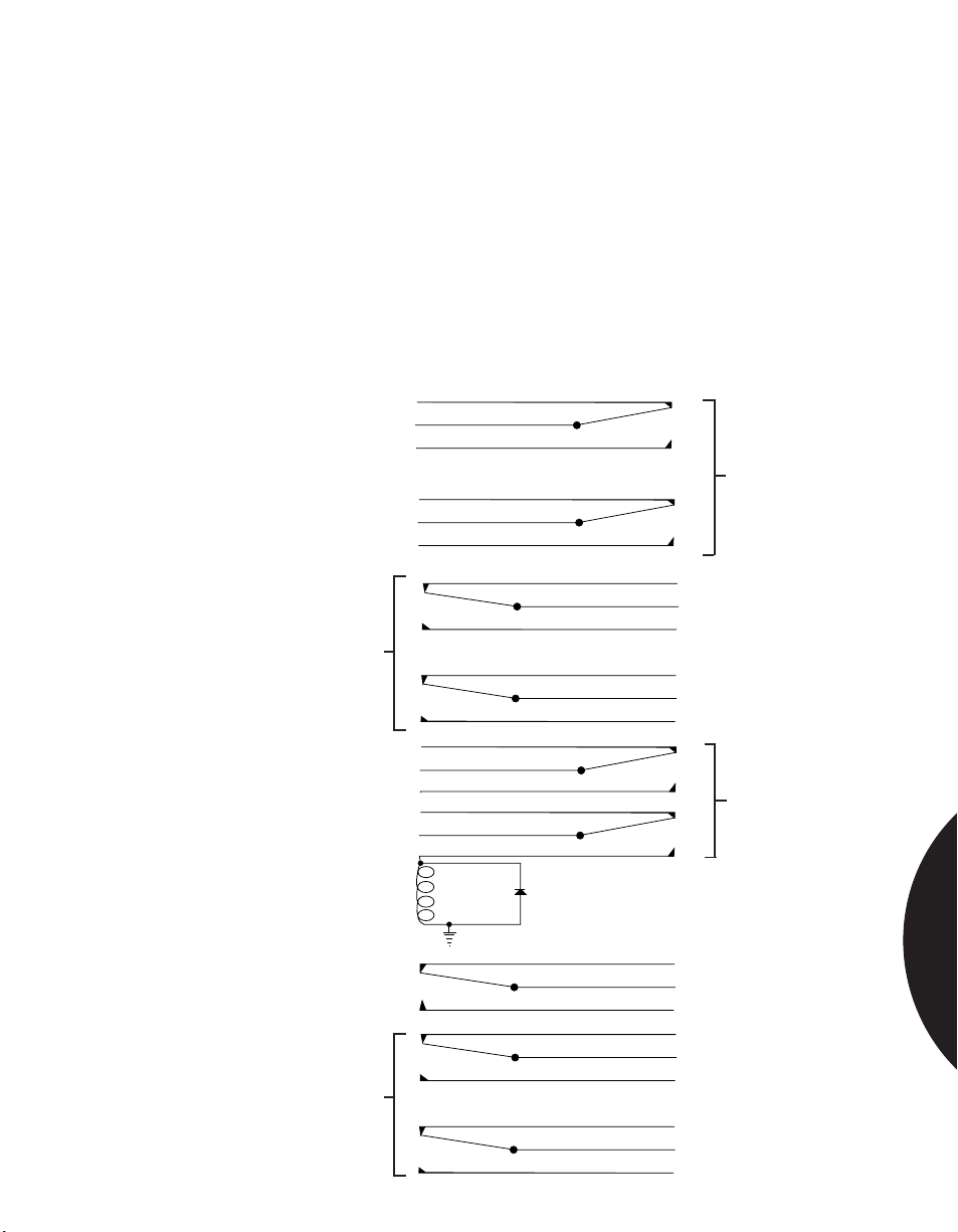
.........................................................................................................................................................................
Phone: 800.894.0412 - Fax: 888.723.4773 - Web: www.clrwtr.com - Email: [email protected]
Introduction
CONTROL SWITCHING
Control Switching Using DPDT Switches
This information describes how to achieve dual switching with one magnetic
contact and one magnet. DPDT magnetic contacts such as the Sentrol 1087D,
1084D, 2507AD, or 2707AD (see catalog) may be used in place of two contacts or
one contact and a floor mat for an annunciator panel. Other applications include
access control multiplex systems, computer monitoring of doors, lighting control
and safety systems. DPDT switches are available in recessed, steel door, surface
and industrial outdoor models.
Note: Each switch is electrically and mechanically isolated from the other and
may switch at a slightly different point.
To Alarm System
DPDT Switch
Contacts
To Annunciator Panel
or Light or Low
Current Chime
To Alarm System
DPDT Switch
Contacts
To CCTV
To Alarm System
DPDT Switch
Contacts
Relay Coil
Relay Contacts
DPDT Switch
Contacts
1 Amp Diode
To 110V Lights,
Horn or High
Current Device
To Alarm System
To Computer or
Access Control
System
MAGNETIC CONTACTS
3.6
Page 70
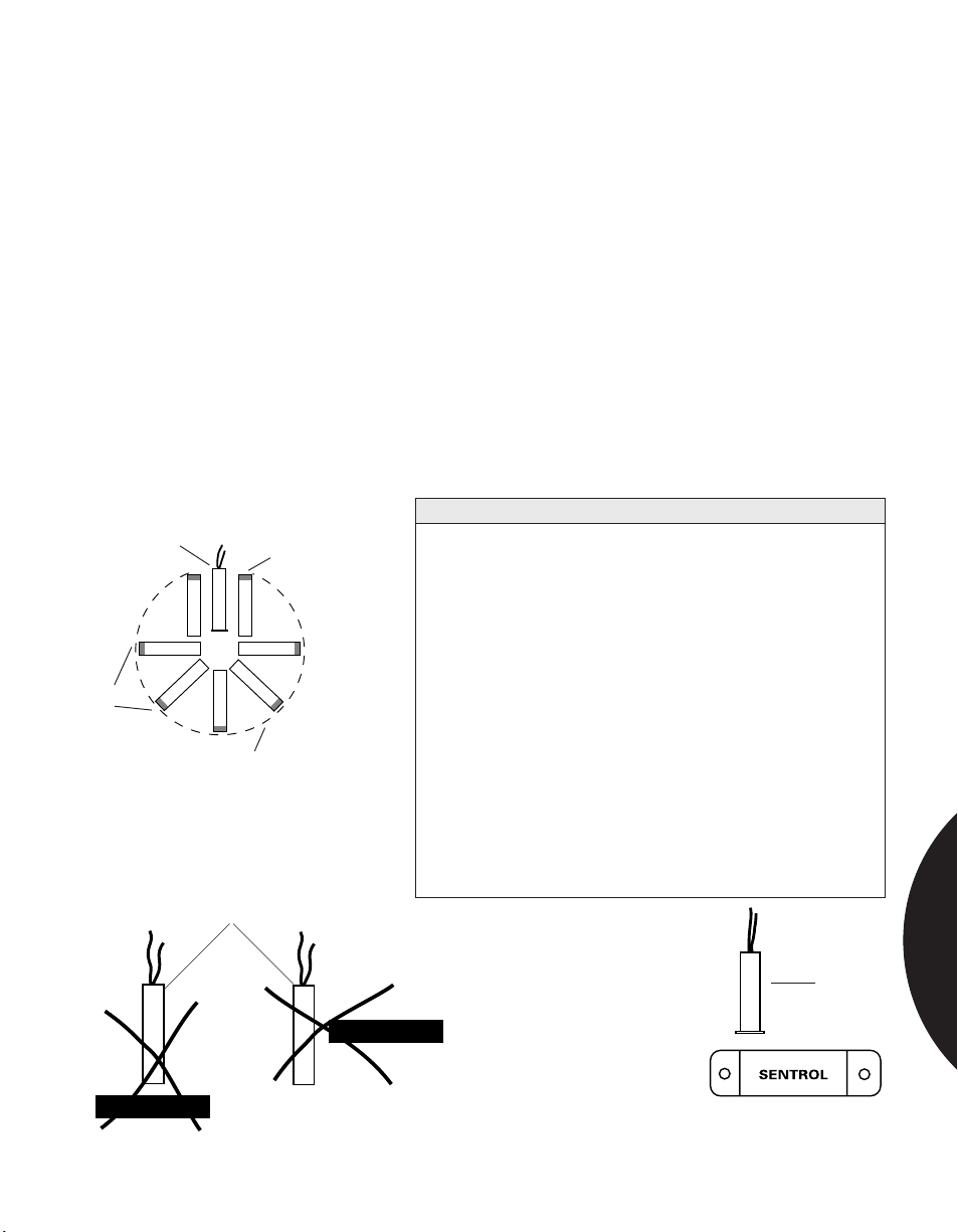
.........................................................................................................................................................................
Phone: 800.894.0412 - Fax: 888.723.4773 - Web: www.clrwtr.com - Email: [email protected]
Introduction
MOUNTING
Mounting Positions for Recessed Switches
Application:
Sentrol recessed contacts can be installed in a variety of positions to accommodate
any application. As shown in Figure 1, the switch and magnet can be mounted
end-to-end within an imaginary arc around the switch, or parallel to the switch. If
using a wide gap switch with a bare magnet, the red end must be mounted away
from the switch (wide gap switches are sensitive to the polarity of the magnet).
Gap distance will vary approximately 20% from the rated gap distance of the
switch, depending on the type of switch and the mounting position. It will be
necessary for the installer to experiment to determine if a given switch will work in
a given position.
Note: Switch and magnet must not be mounted in a “T” configuration as shown
in Figure 2. In cases where a surface magnet must be used with a recessed switch,
use a surface mount switch from the 1082 switch series. Mount the magnet as
shown in Figure 3.
Pro-Tips For Reliable Installation of Magnetic Contacts
Recessed
Switch
Magnets
Red End
(if Wide Gap)
Approximate arc through
Which magnets may be
rotated
Figure 1. Acceptable Magnet
Mounting Positions
1. When installing concealed switches in green lumber...
to prevent switch damage as the lumber dries, twists,
and contracts.
a. Over-drill (loose fit) the mounting hole. Use RTV
(Sentrol 1905) to hold the unit in place.
b. As alternate, use adapter such as Sentrol 1908 model.
c. Use Sentrol model 1275 or 1275W Wing Fit™ model.
2. To protect loose-fitting doors from false alarms...
a. Mount the switch and magnet near the hinge side
of the door.
b. Use a Sentrol wide gap unit to assure
trouble-free performance.
3. To protect steel doors...
a. Use wide gap switches for maximum tolerance.
b. Use recessed switches that provide adequate insulation
from steel (such) as Sentrol 1078 or 1078C).
MAGNETIC CONTACTS
Switch
Magnet
Magnet
Figure 2.
Incorrect Mounting Positions
Figure 3. Recessed Switch with
Surface Mount Magnet
Magnet
Recessed
Switch
3.7
Page 71
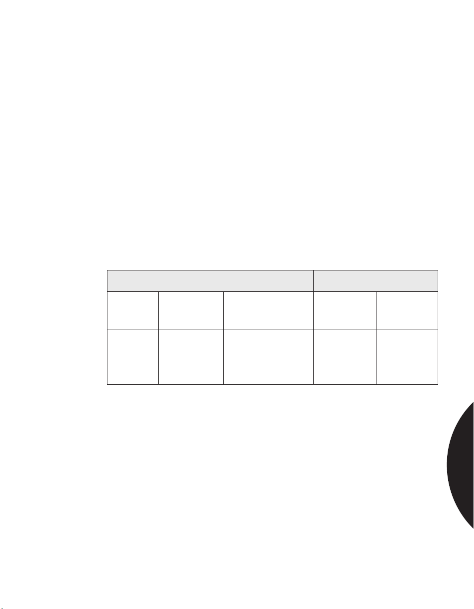
.........................................................................................................................................................................
Phone: 800.894.0412 - Fax: 888.723.4773 - Web: www.clrwtr.com - Email: [email protected]
Introduction
MOUNTING
Mounting Data for Steel Doors and Windows
The results of test runs in which Sentrol magnetic contacts were used on steel are
given here.
Test Procedure
Each sample was selected at random from finished goods inventory. Tests on each
contact were run to measure pull in (make), and drop out (break) distances prior to
mounting on the 6" wide, 16" long, and 1/2" thick steel plate.
Each contact pull in (make) gap distance was measured:
1. With contact and magnet attached directly to the 1/2" steel plate with no
spacers.
2. With a single, .125" spacer under both the contact and magnet. A 1/2" spacer
was used under both the magnet and contact in the 2505 test.
All measurements were recorded to the nearest 0.05" (fifty-thousandths of an
inch).
Test Results
All dimensions in inches.
Contacts mounted on 1/2” Control tests in air
thick steel plate 6” X 16”
Sentrol A B Make Break
Switch Make Distance Make Distance Distance Distance
Number w/o spacer with spacer under Pull in Drop out
1085T .4 .55 .8 1.0
1085-W .75 .95 1.5 2.1
1082T .55 .7 1.25 1.5
1084T .4 .6 1.0 1.2
1084T-W .9 1.2 2.3 2.55
2505 1.2 2.2 4.2
Conclusion
The Sentrol surface-mounted contacts should be satisfactory for applications in
such areas as steel fire doors, safes, file cabinets, truck doors, and roll-up garage
doors. Customers should be reminded to allow plenty of safety factor in
installation. Sentrol recommends installing the contact and magnet with no more
separation than about 50% of the pull in distance. For instance, on the Sentrol
1084TW measurements on steel, a maximum separation of 0.5" to 0.6" should
provide a reliable system.
Rules of Thumb
• Gap on steel is approximately half the distance achieved in air.
• Space switch and magnet at approximately 25% of rated gap in air for safety
factor.
• Use a spacer whenever it is practical. If only one spacer is used, mount it under
the magnet.
• Applications on steel do not “drain” the magnet, but they do reduce the
magnetic field.
magnet & contact
MAGNETIC CONTACTS
3.8
Page 72
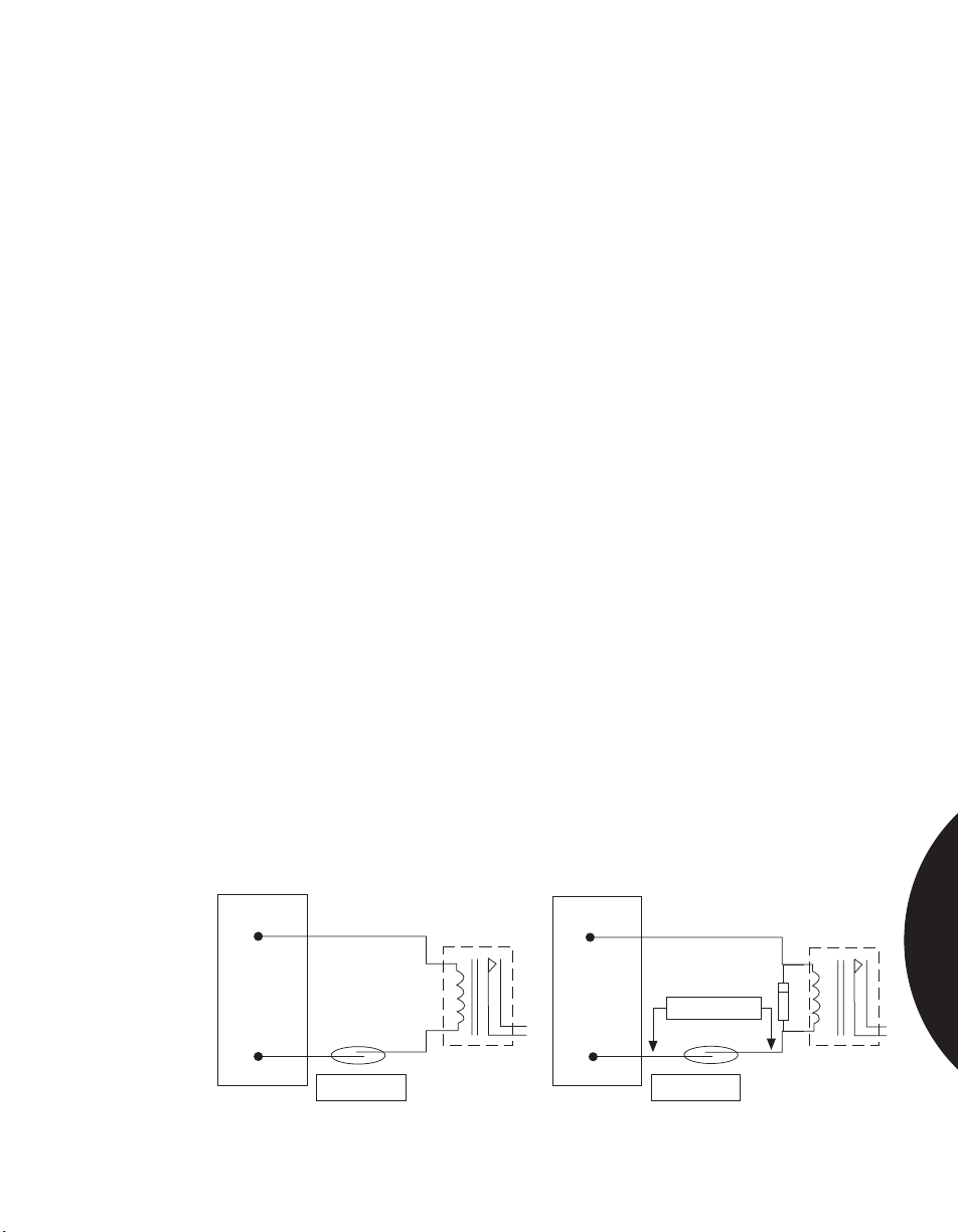
.........................................................................................................................................................................
Phone: 800.894.0412 - Fax: 888.723.4773 - Web: www.clrwtr.com - Email: [email protected]
Introduction
PROTECTING AGAINST VOLTAGE SPIKES
The Sticking Reed Switch Problem
When magnetic reed switches are wired in line with relay devices with coils, the
reverse voltage spike generated when current is removed from the relay can fuse
the switch contacts together.
Figure 1 shows that when the contact is closed, current flows through the relay coil
and magnetizes the iron core. When the contact is opened, current from the power
supply stops and the magnetism of the relay iron drops to zero instantly. The
collapsing magnetic field draws voltage into the relay coil. Since the coil is open
(open reed switch) and there is no circuit loading to limit the voltage, spikes from
the open relay can reach 500 volts or more, causing arcing across the reed contacts.
(Most of Sentrol’s reeds arc between 150 and 200 volts, well within this reverse
voltage kick.)
Repeated arcing roughens and pits the reed switch blades until they eventually
stick together mechanically. Installers often find that tapping on the switch will
cause the contacts to release (open). The “fix” is only temporary, however.
Correcting the Problem for DC Circuits
Voltage kicks or transients from DC circuits are easily controlled by adding a diode
across the relay coil, as in Figure 2. The diode has no affect on the circuit when
the current flows in the right direction. However, when current from the power
supply stops suddenly and the relay coil generates a reverse voltage, it shorts
through the diode. Note that the stripe on the diode points toward the + voltage.
The diode used should be a #1N4002, 1N4003, 1N4004 or equivalent.
... and for AC Circuits
In AC circuits, current flows through the relay coil in both directions. Using a
diode would simply short out half of every cycle. However, a transient protection
diode, called a TransZorb
direction as shown in Figure 2. TransZorb must be selected to fit the voltage used
in the circuit. To find the correct TransZorb voltage rating, multiply the circuit
voltage times 1.414. For example, in a 24 volt circuit a TransZorb rated at 34 volts
or more may be used (24 x 1.414 = 34).
®
, can be used to clip off voltage spikes in either
MAGNETIC CONTACTS
+
D.C.
Power
Supply
-
Figure 1
Relay
Switch
Magnet
+
D.C.
Power
Supply
-
Figure 2
Diode
TransZorb®
Switch
Magnet
Relay
3.9
Page 73
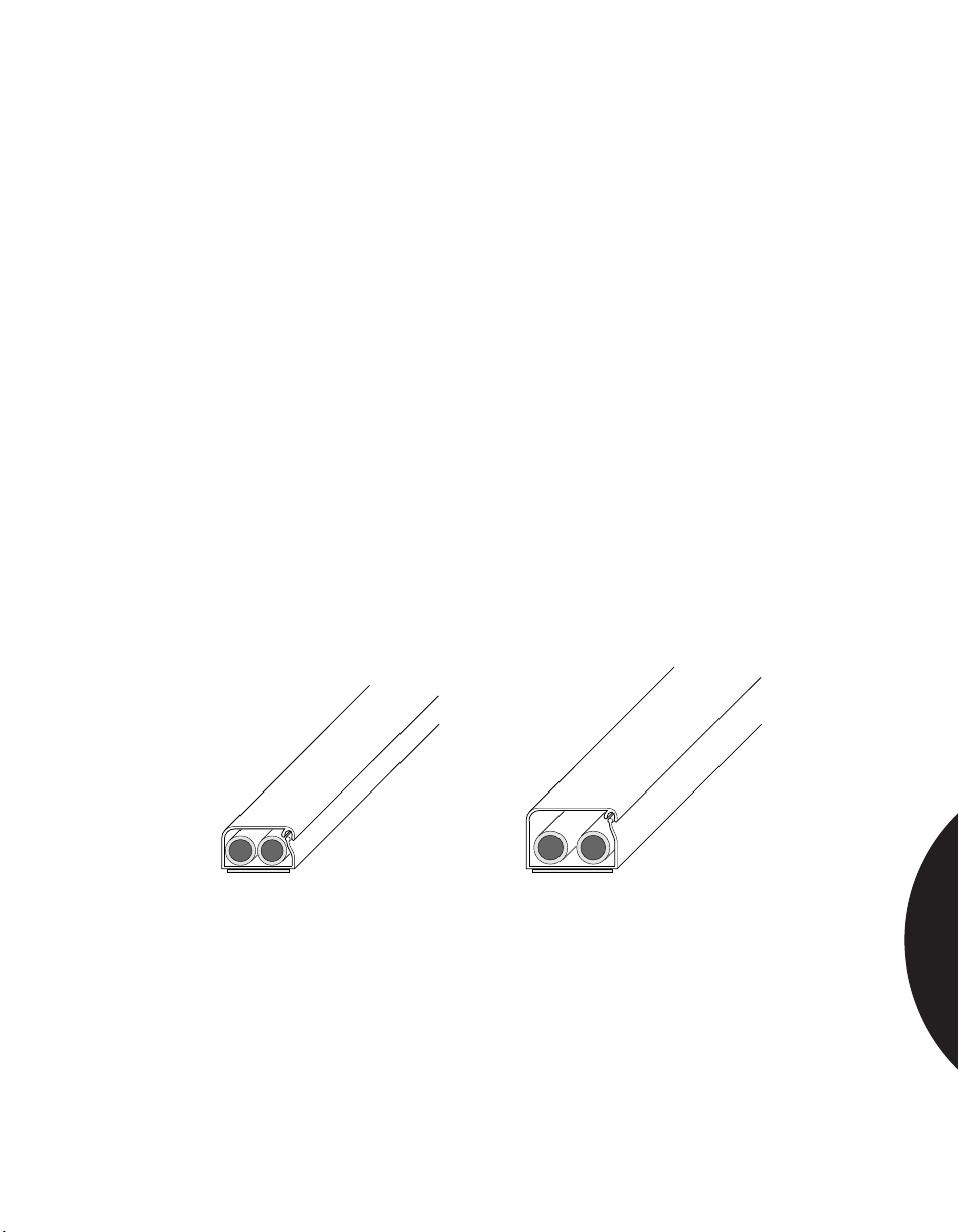
.........................................................................................................................................................................
Phone: 800.894.0412 - Fax: 888.723.4773 - Web: www.clrwtr.com - Email: [email protected]
Introduction
CONCEALING SURFACE WIRING WITH
NICE-DUC
Low-Profile, Unobtrusive Design
Nice-Duc is the ideal self-adhesive wiring duct for concealing low voltage alarm
systems in completed structures. Nice-Duc blends unobtrusively into any
environment with a choice of decorator colors.
For easy installation, Nice-Duc features a hinged design on one side and a slot
tract on the other that snaps shut with the wire inside. The thin wall design is easy
to cut to fit. Alcohol cleaning pads are included to remove dirt from installation
surfaces.
Nice-Duc uses an epoxy-based adhesive tape with low initial tack so it can be
easily adjusted. After 24-hours, the adhesive begins to cure, providing a permanent
adhesive bond.
Nice-Duc comes in two sizes:
Mini: 1/4" high by 7/16" wide
Standard: 3/8" high by 5/8" wide
All sizes come in 60" (152.4 cm) lengths. A variety of right angles,
T-connectors, inside and outside corners and end caps are also available.
To order, call: 1-800-547-2556.
®
Mini— 1/4" (0.64 cm) high
x 7/16" (1.11 cm) wide
x 60" (152 cm) long
Available in: white, off-white, brown
Standard— 3/8" (0.953 cm) high
x 5/8" (1.59 cm) wide
x 60" (152 cm) long
Available in: white, off-white, brown
MAGNETIC CONTACTS
3.10
Page 74
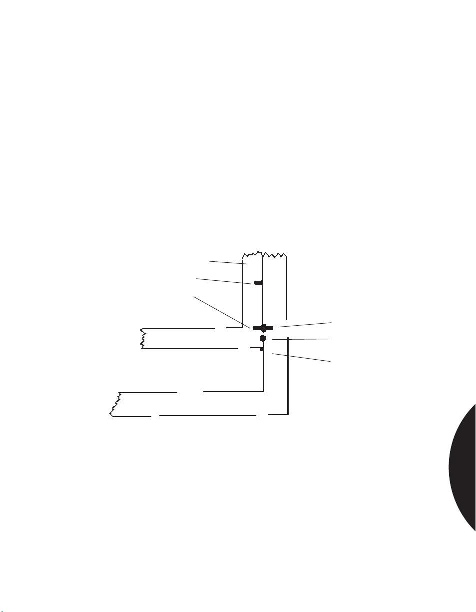
.........................................................................................................................................................................
Phone: 800.894.0412 - Fax: 888.723.4773 - Web: www.clrwtr.com - Email: [email protected]
Introduction
VENTILATING WINDOWS WITHOUT
FALSE ALARMS
Sentrol recommends two methods for opening windows for ventilation without
causing a false alarm.
First, a small dot, either adhesive or painted, can be added to both the window
frame and window jamb that marks the spot above which the window should not
be opened. The user simply aligns the halves of the dot as shown below.
Second, a window stop can be provided so that the window cannot pass the alarm
point in normal usage. Drill a hole in the jamb for the stop. Use a nail or small
dowel as the stop. The dowel or nail should protrude from the hole so it supports
the opened window, as shown below.
See also “Ventilating Windows With a Wide Gap Magnet” — page 96.
Window Frame
Magnet #1
Magnet #2
Switch
Green Dot
Stop
Open for ventilation
MAGNETIC CONTACTS
3.11
Page 75
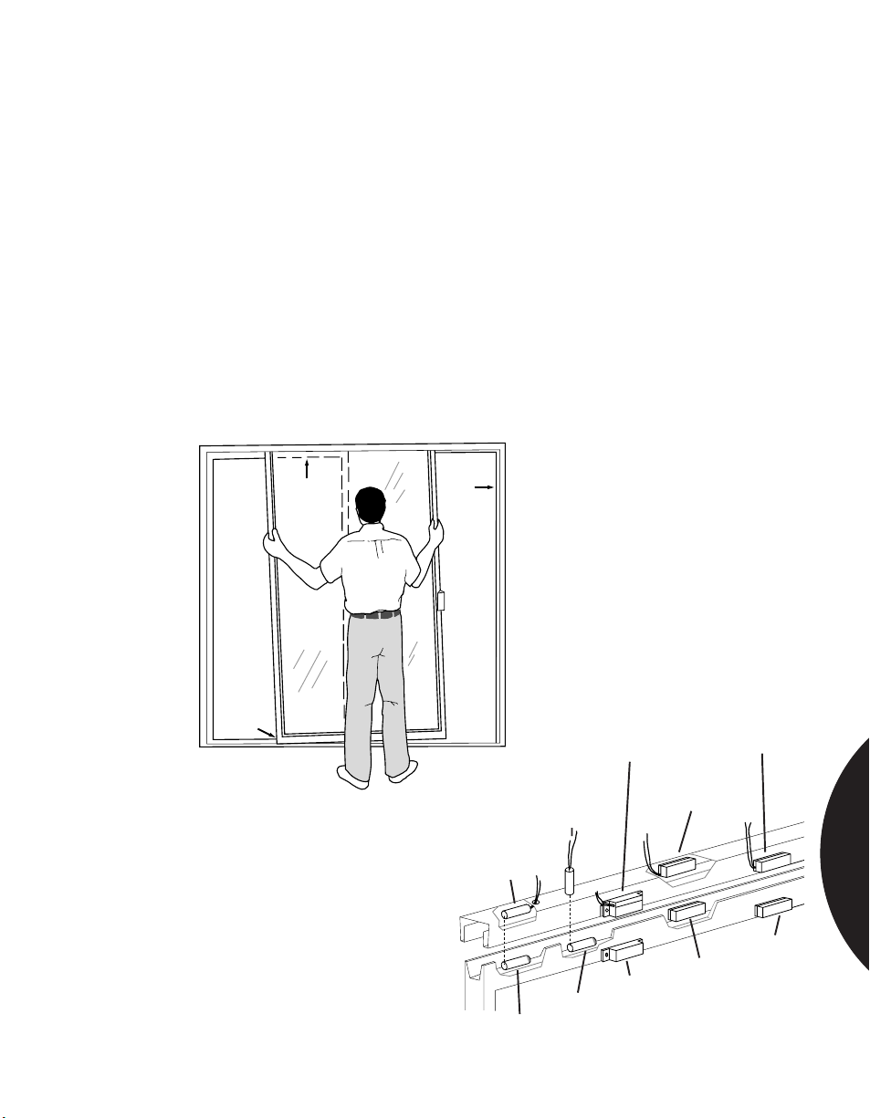
.........................................................................................................................................................................
Phone: 800.894.0412 - Fax: 888.723.4773 - Web: www.clrwtr.com - Email: [email protected]
Residerntial & Commercial Applications
PROTECTING SLIDING ALUMINUM DOORS
APPLICATION
INSTALLATION
RECOMMENDED
PRODUCTS
Protecting sliding aluminum doors against unauthorized entry.
There are several methods for protecting sliding aluminum doors:
• Parallel recess mount
• Perpendicular recess mount
• Parallel recess mount with adhesive surface mount switch
• Screw-down surface mount — do not drill into glass!
• Adhesive surface mount
The installation technique you select will depend on the gap distance available
and ease of installation.
Remove door as shown in Figure 1. Figure 2 illustrates mounting positions.
1035, 1035W, 1055, 1055W, 1075, 1075W, 1085, 1085T, and 5725 ShatterSwitch.
Figure 1.
a. Open door as far as required
b.
a.
b. Lift door straight up into upper channel
c. Pull door out from the bottom
MAGNETIC CONTACTS
c.
Perpendicular
Recessed
Mount Switch
Parallel
Recessed
Mount
Switch
Magnet
Figure 2.
Surface
Mount
Switch
Recessed
Surface
Switch
Recessed
Surface
Magnet
Mount
Magnet
Note: Align end of switch with end of magnet.
Surface
Magnet
Surface
Switch
Surface
Magnet
3.12
Page 76
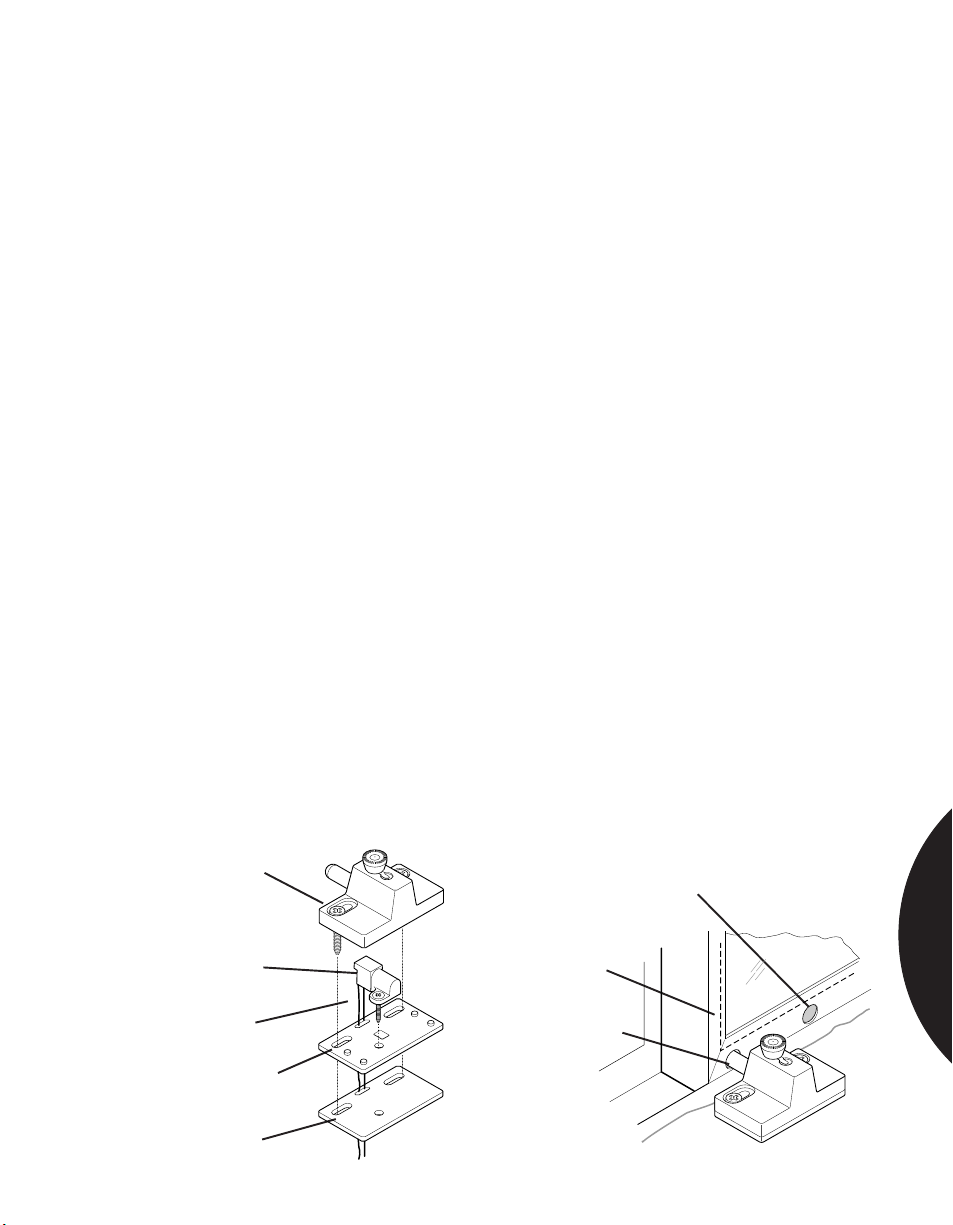
.........................................................................................................................................................................
Phone: 800.894.0412 - Fax: 888.723.4773 - Web: www.clrwtr.com - Email: [email protected]
Residential & Commercial Applications
PROTECTING PATIO DOORS
APPLICATION
INSTALLATION
RECOMMENDED
PRODUCTS
Use the 3610 Patio Door Magnetic Contact, which contains a switch assembly and
plunger that mount independently of each other. The magnetic contact provides
alarm annunciation and the locking mechanism secures the sliding glass door. In
the event the door is pried from the channel, and the force dislodges the plunger
housing, it creates an alarm condition.
Close sliding door or window. Position switch next to the door on the side opposite
the latch. Using the mounting plate provided and with optional spacers if required,
adjust the height of the unit so the plunger pin can extend unobstructed into the
door frame without interference from the track.
Once the height is determined, adjust the unit horizontally to the optimum
plunger position. Verify the plunger can travel into the door or window frame at
least 1/4 inch.
CAUTION: Make sure the plunger hole will not interfere with the glass pane or
weather stripping. Be sure to note the location of any wheels in the door before
drilling.
Using the spacer as a template, set the switch housing onto the spacer and mark
the holes. Drill a hole into the floor or casing for the wire, and connect the leads to
a normally closed alarm loop. Mount the plastic switch housing with the #6 screw
provided, using the mounting plate or optional spacer if needed.
Drill two mounting holes for the metal housing. Mount the metal housing using
the #8 screws provided. With the door or window in the closed position, mark the
location of the plunger on the frame. Open the door or window and drill a
minimum 11/32 inch hole into the marked location on the frame, being careful not
to over-drill the hole. Maximum travel of the plunger will not exceed 3/8 inch.
To ventilate with the door or window, drill an additional hole in the frame. This
allows the door to be open but still protected.
3610
Plunger
housing
Optional hole
for venting
MAGNETIC CONTACTS
Switch
housing
Wires
Mounting
Plate
Spacer
Edge of glass
(inside frame)
Drill 11/32" hole
3.13
Page 77
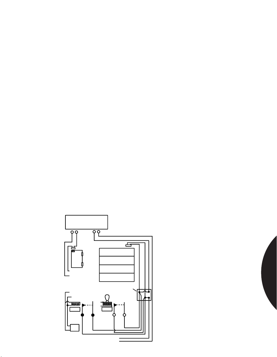
.........................................................................................................................................................................
Phone: 800.894.0412 - Fax: 888.723.4773 - Web: www.clrwtr.com - Email: [email protected]
Residential & Commercial Applications
PROTECTING AUTOMATIC GARAGE DOOR —
SWITCH SHUNTING
APPLICATION
INSTALLATION
How to provide “on” and “off” alarm protection when an exit delay is part of the
system, and entrance and/or exit is via a door to the garage. The garage door must
also have an automatic opener that has a timed entrance light.
Two 110-volt AC SPST relays are needed (hermetically sealed preferred). The coil
of Relay No. 1 is placed across the AC line going to the motor which opens the
garage door. The coil of Relay No. 2 is placed across the AC line going to the light
on the garage door opener.
Both sets of the 110-volt relay contacts are placed in parallel, and together are
connected across the garage door contact already in the protective loop. A junction
box can be used to ease wiring.
Theory of Operation: Before leaving home, the user arms the alarm system and
leaves via the door leading to the garage, which would normally be on the Exit/
Entry delay loop. As user signals garage door to rise, Relay No. 1 activates as the
motor starts and shunts the garage door contact, thus preventing an alarm. As door
rises, the light comes on and Relay No. 2 activates, also shunting the garage door
contact. Once the door is all the way open, the motor shuts off, causing Relay No.
1 to drop out. However, the light remains on for a fixed period of time, so Relay
No. 2 remains activated, still shunting the garage door contact and preventing an
alarm. Prior to the light going out (this should be timed), the user exits from the
garage and signals for the door to lower. The motor starts, again activating Relay
No. 1 and shunting the garage door relay as before. The light, still on, restarts the
timed cycle, and Relay No. 2 remains activated. When the door is completely
closed, Relay No. 1 drops out. After a fixed time, Relay No. 2 drops out and
returns the loop to the garage door contact and normal operation.
Exit/Entry
Delay Loop
Protective
Zone Loop
MAGNETIC CONTACTS
Door Contact
Door
to
Garage
To other delay points
And/Or E.O.L. Resistor
To Motor
Power Source
N.O. COM.
Garage Door
Relay 2Relay 1
N.O.
No. 1990
Junction Box
Light activated
by motor
COM.
3.14
Page 78
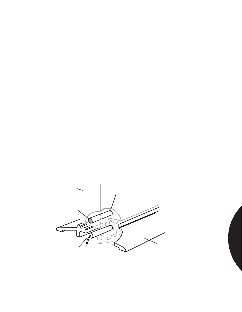
.........................................................................................................................................................................
Phone: 800.894.0412 - Fax: 888.723.4773 - Web: www.clrwtr.com - Email: [email protected]
Residential & Commercial Applications
PROTECTING WOOD DOOR THRESHOLDS
WITH RECESSED CONTACTS
APPLICATION
INSTALLATION
RECOMMENDED
PRODUCTS
For wood doors with aluminum thresholds, it is sometimes convenient to mount
the magnet in the bottom of the door and the switch in the hollow space beneath
the threshold.
Note: Because of the distance between the magnet and switch, a Sentrol wide gap
switch should be used.
Select a recessed-mount wide gap switch.
Drill horizontal hole for magnet in outside edge of door. Coat magnet with RTV
mounting compound. Insert magnet in hole. If using a wide gap switch with bare
magnet, insert with red end of magnet toward outside of door (switch is polarity
sensitive).
Remove threshold.
Attach switch on inside of threshold with RTV mounting compound. Position it so
it will be directly beneath (and parallel to) magnet when threshold is replaced.
Replace threshold.
Test switch with ohmmeter while opening and closing door.
Connect switch to alarm loop.
1055W, 1059W, 1065W, 1075W, RTV 1905.
Door
Red End
Switch
Figure 1. Wood Door Installation
Magnet
Aluminum Threshold
MAGNETIC CONTACTS
3.15
Page 79
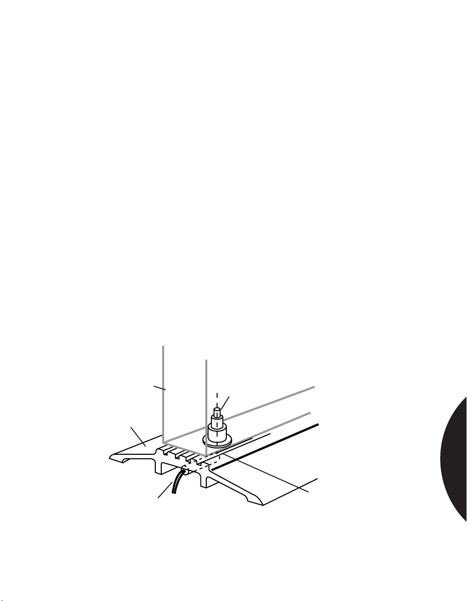
.........................................................................................................................................................................
Phone: 800.894.0412 - Fax: 888.723.4773 - Web: www.clrwtr.com - Email: [email protected]
Residential & Commercial Applications
PROTECTING STEEL DOORS
WITH THRESHOLD CONTACTS
APPLICATION
INSTALLATION
RECOMMENDED
PRODUCTS
For steel doors with aluminum thresholds, it is sometimes convenient to mount
the magnet in the bottom of the door and the switch in the hollow space beneath
the threshold.
Note: Because of the distance between the magnet and switch, a Sentrol wide gap
switch should be used.
Use a Sentrol steel door magnet combined with a Sentrol wide gap switch.
Remove door from hinges. Drill 1" (2.54 cm) diameter hole in bottom of door
about 2" (5 cm) from front edge of door. Glue with RTV or epoxy and snap-fit
magnet into hole.
Remove threshold.
Attach switch on inside of threshold with RTV mounting compound. Position it so
it will be directly beneath and perpendicular to magnet with end centered beneath
it when threshold is replaced.
Replace threshold and door.
Test for correct operation with ohmmeter while opening and closing door.
Connect switch to alarm loop.
1055W, or 1075W, with 1921 magnet, RTV 1905.
Door
Aluminum
Threshold
1055-W or 1075-W Switch
Figure 2. Steel Door Installation
1921 Magnet
(in 1” diameter hole)
Center end of switch under
magnet
MAGNETIC CONTACTS
3.16
Page 80

.........................................................................................................................................................................
Phone: 800.894.0412 - Fax: 888.723.4773 - Web: www.clrwtr.com - Email: [email protected]
Residential & Commercial Applications
PROTECTING WOOD/STEEL DOORS
WITH ROLLER PLUNGER CONTACTS
APPLICATION
INSTALLATION
RECOMMENDED
PRODUCTS
Wood and steel doors can be protected with roller plunger contacts that can be
installed without removing the door from its hinges. The versatile Sentrol 3005
and 3008 Roller Plunger Contacts can also be used on windows and sliding patio
doors. Roller plungers are more versatile than plunger switches, which work in
limited applications. The 3008 is designed specifically for fight, thin-framed
window and door applications.
Roller plunger switches can also be used to protect high-value objects such as
antiques, rare books, or works of art by placing the object on the recessed contact.
Note: In order to comply with UL installations, the contact should not be used on
exterior doors that open outward.
The roller plunger contact must be mounted on the hinge side of the door or
window to be protected.
Open the door or window. Drill a 3/4" (1.9 cm) diameter hole in frame. Hole
should be 1.5" (3.81 cm) deep for the 3005 and 3/4" (1.9 cm) deep for the 3008.
Run wire through the frame and connect switch to the alarm loop. Insert switch in
hole and test for proper operation by opening door or window.
Screw switch in place.
3005, 3008
0.90"
2.29 cm
FRONT VIEW
3.05 cm
0.75"
1.905 cm
Flange thickness 0.05"
1.50"
3.81 cm
1.75"
4.45 cm
Models 3002, 3003, 3004
Models 3005, 3006, 3007
Models 3005, 3006, 3007
1.50"
3.81 cm
1.188"
3.02 cm
Models 3002, 3003, 3004
Side View
0.800"
2.03 cm
0.25" (635 cm)
0.750"
1.905 cm
0.75"
1.905 cm
0.050"
0.127 cm
Model 3008
1.20"
1.60"
4.07 cm
3.17
MAGNETIC CONTACTS
Page 81
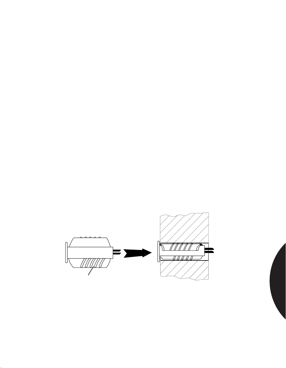
.........................................................................................................................................................................
Phone: 800.894.0412 - Fax: 888.723.4773 - Web: www.clrwtr.com - Email: [email protected]
Residential & Commercial Applications
PROTECTING DOORS AND WINDOWS
WITH UNEVEN WIRING HOLES
APPLICATION
INSTALLATION
RECOMMENDED
PRODUCTS
It may happen, during installation, that holes are over-drilled, under-drilled, or
have an uneven diameter. Oversized holes can occur due to difficulties in drilling,
especially in tight quarters or enclosed spaces. Press-fit 3/8" (0.95 cm) diameter
switches can actually fall out of over-sized holes even when they initially seem to
fit well. This necessitates a costly service call and the use of adhesives (which take
time to apply, and also increase service time should the switch need to be
removed).
Additionally, many switches cannot withstand the pressure of green wood in new
construction. Green wood dries and shrinks, damaging reed contacts.
Sentrol’s 1275 addresses these problems. Its flexible, collapsible wings
surrounding the switch “barrel,” accommodate smaller or larger holes, and cushion
the reed. With a 1-1/4" (3.175 cm) gap, the 1275W also reduces costly time aligning
the switch and magnet on loose-fitting doors and windows.
Decide on best placement of switch in header or sill, and best position of magnet
in door or window frame. Drill 3/8" (0.95 cm) diameter holes. Switch measures 1"
(2.54 cm) long. The magnet is about 1-1/3" (3.39 cm) long.
Pull wire and connect to switch. Squeeze 1275’s “wings” and press fit switch into
place. Then press fit magnet into its hole.
Test for continuity, then connect switch to loop.
1275, 1275W
Wings
MAGNETIC CONTACTS
3.18
Page 82
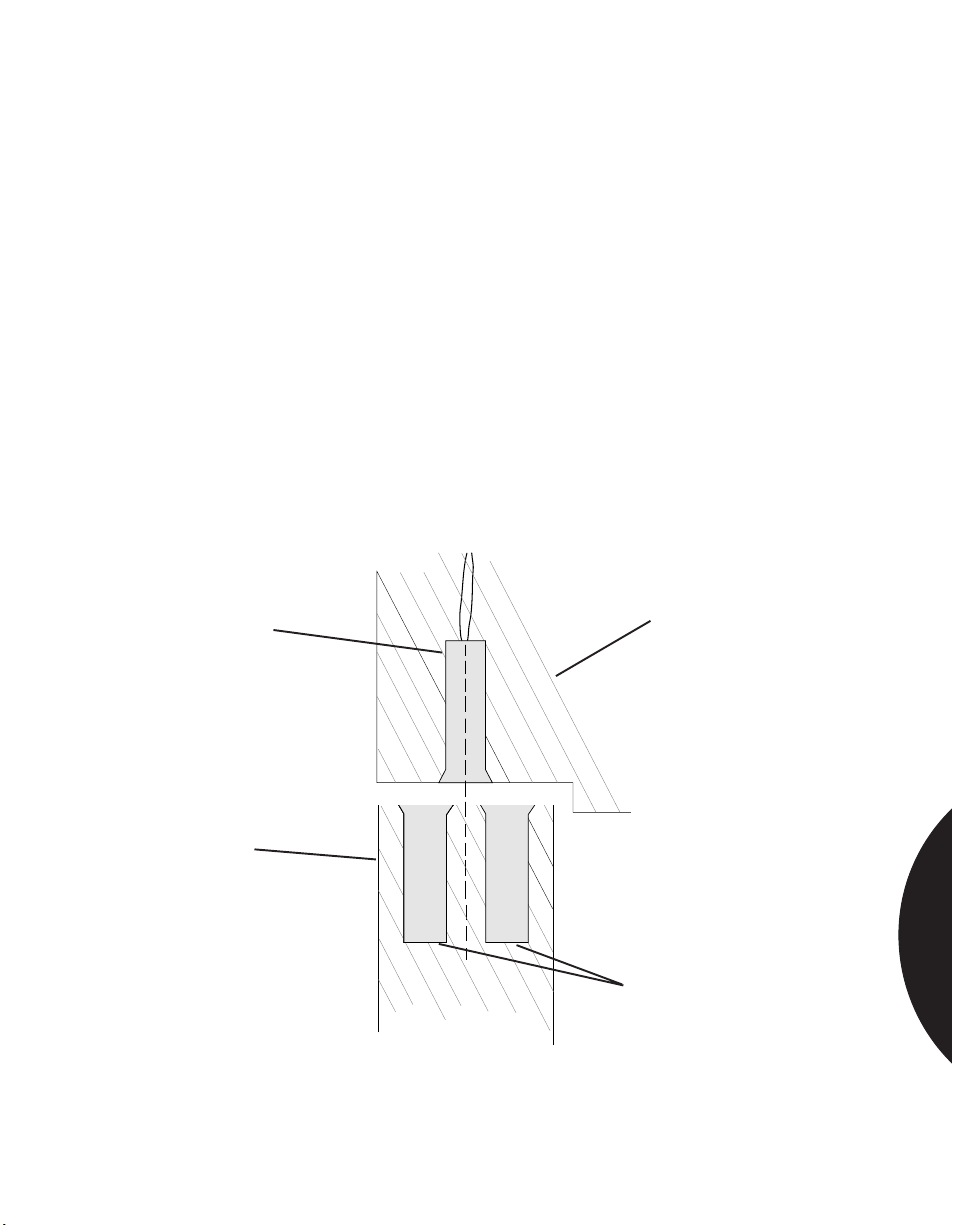
.........................................................................................................................................................................
Phone: 800.894.0412 - Fax: 888.723.4773 - Web: www.clrwtr.com - Email: [email protected]
Residential & Commercial Applications
INCREASING GAP DISTANCE OF RECESSED
SWITCH WITH SECOND MAGNET
APPLICATION
INSTALLATION
RECOMMENDED
PRODUCTS
You can increase the gap distance of a recessed switch in a door about 40% by
placing two magnets side-by-side. This is helpful if you need to increase the gap
distance but do not have a wide gap switch.
Note: Mount magnets with like poles in the same direction (magnets will actually
push away from each other when so mounted).
Note: Observe correct polarity for wide gap switches (red ends of magnets must
be mounted away from switch).
Mount switch as desired.
Drill holes for magnets, spacing them equal distances from a line drawn through
the center of the switch. Mount magnets as close together as possible.
Attach ohmmeter to switch leads and test for proper operation.
Connect switch to alarm loop. Retest for proper operation.
1075, 1075W, 1275, 1275W, with additional 1924 magnet
Switch
Door
Door Frame
1924 Magnets
MAGNETIC CONTACTS
3.19
Page 83
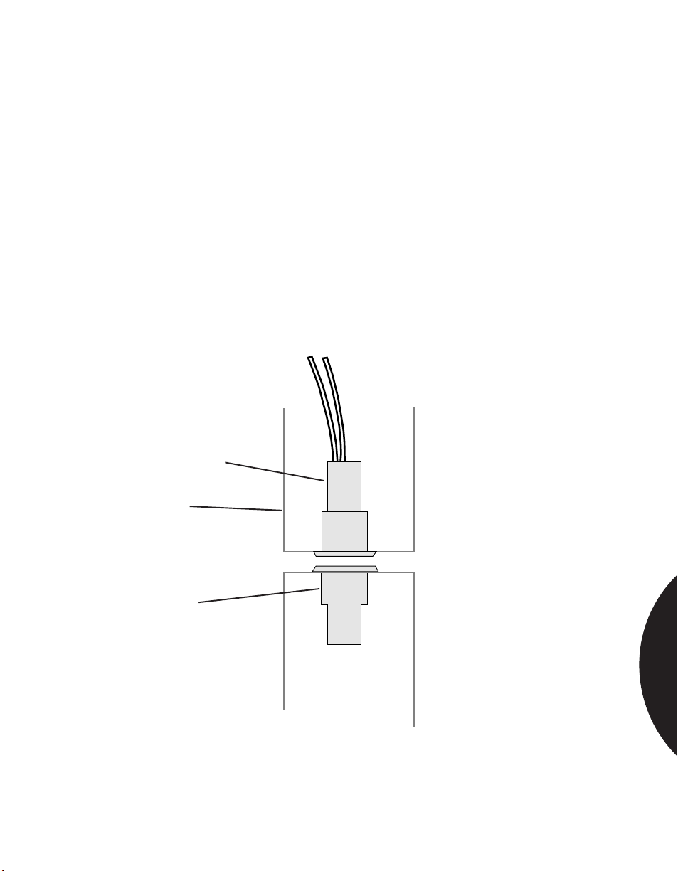
.........................................................................................................................................................................
Phone: 800.894.0412 - Fax: 888.723.4773 - Web: www.clrwtr.com - Email: [email protected]
Residential & Commercial Applications
REPLACING MECHANICAL RECESSED
TYPE SWITCHES IN DOORS
APPLICATION
INSTALLATION
RECOMMENDED
PRODUCTS
Floating magnet-type mechanical switches can fail due to corrosion (unit is not
hermetically sealed), uneven wear of the plastic body, or crushing of the unit
between the door and frame. The use of a Sentrol switch is an attractive
alternative.
If the unreliable switch is a “repel” magnet type, remove the switch and magnet
and replace with hermetically sealed, 3/4" (1.9 cm) diameter Sentrol 1078C-1.
Hole should be 1-1/2" (3.81 cm) deep. The 1078C-1 self-locks in place, requiring
no screws.
1078C
1078C Switch
Frame
Magnet
MAGNETIC CONTACTS
3.20
Page 84
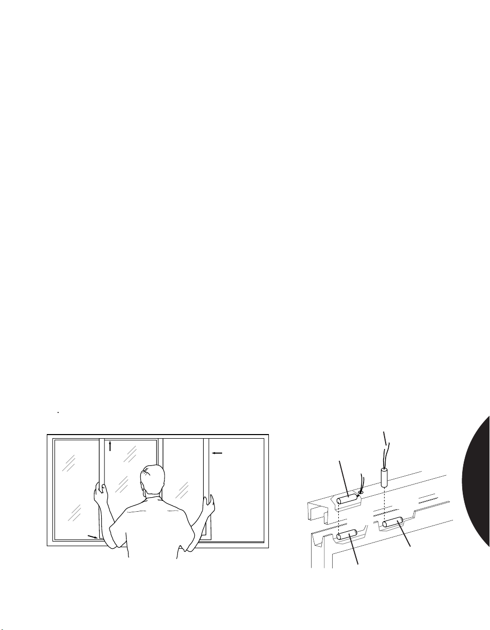
.........................................................................................................................................................................
Phone: 800.894.0412 - Fax: 888.723.4773 - Web: www.clrwtr.com - Email: [email protected]
Residential & Commercial Applications
PROTECTING SLIDING ALUMINUM WINDOWS—
APPLICATION 1
INSTALLATION
RECOMMENDED
PRODUCTS
This page and the following two pages provide installation instructions for
protecting sliding aluminum windows with recessed or surface mount switches,
or a combination of both.
Installation with Removal of Window
Remove window from frame as follows (Figure 1):
a. Open window as far as required (some windows have spring locks in upper
frame channel past which the window must be opened before it can be
removed).
b. Lift window straight up into upper channel.
c. Pull window straight out from bottom.
Locate desired mounting position for switch — either parallel to magnet or
perpendicular (Figure 2).
Drill hole in window frame. Run wires. Insert switch into frame.
Mount magnet on inside of upper window channel, toward top of channel, with
RTV mounting compound. RTV should sufficiently set in about 15 minutes to
permit replacement of window into frame.
Reinsert window in frame by reversing procedure in Step 1.
Check continuity with window in closed position.
Notes: Wide gap switches are polarity sensitive. Red tip of magnet must be
aligned as shown.
Magnet must not be centered under switch — a null may result, and switch will
not operate.
1055, 1055W, 1065, 1075, 1275W, RTV 1905
b.
a.
Parallel
Recessed
Mount Switch
Perpendicular
Recessed
Mount Switch
MAGNETIC CONTACTS
Red end if
wide gap
Magnet
Figure 1.
Red end if
wide gap
c.
Magnet
Note: Align end of switch with end of magnet
Figure 2. Recessed Installation
3.21
Page 85
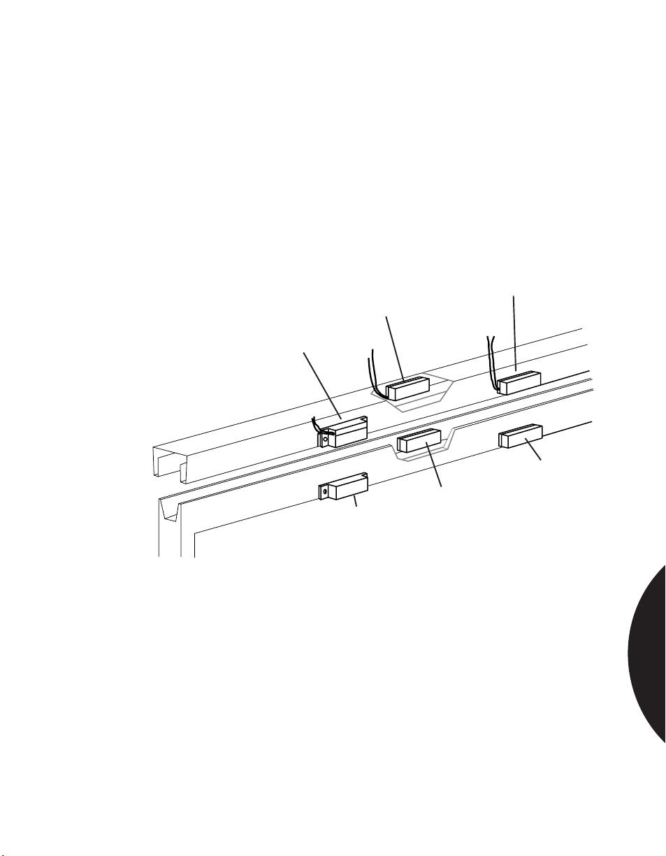
.........................................................................................................................................................................
Phone: 800.894.0412 - Fax: 888.723.4773 - Web: www.clrwtr.com - Email: [email protected]
Residential & Commercial Applications
PROTECTING SLIDING ALUMINUM WINDOWS
APPLICATION 2
INSTALLATION
RECOMMENDED
PRODUCTS
Installation without Removing Window
Removal of window is not necessary unless switch leads are to be run into channel.
If using self-adhesive switch, clean surface with alcohol before mounting to ensure
good bond. Mount switch on sash in desired position (Figure 3). Mount magnet on
window directly opposite switch when window is closed.
Check for continuity with window in closed position.
1035, 1035W, 1085, 1085T
Surface
Switch
Surface
Magnet
Surface
Mount
Switch
Surface
Mount
Magnet
Recessed
Surface
Switch
Recessed
Surface
Magnet
MAGNETIC CONTACTS
Figure 3. Surface Installation
3.22
Page 86
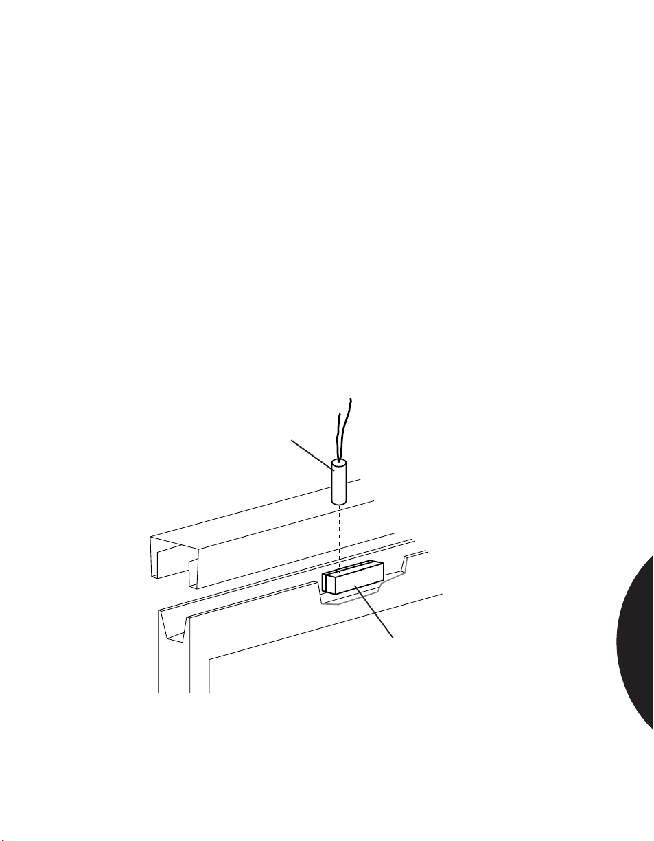
.........................................................................................................................................................................
Phone: 800.894.0412 - Fax: 888.723.4773 - Web: www.clrwtr.com - Email: [email protected]
Residential & Commercial Applications
PROTECTING SLIDING ALUMINUM WINDOWS
APPLICATION 3
INSTALLATION
RECOMMENDED
PRODUCTS
Combined Recessed and Surface Installation
Remove window from frame (see instructions in “Installation with Removal of
Window”— Application 1, page 93).
A 1075 or 1075W switch with a 1927 magnet is ideal for this application. The
magnet can be quickly installed using double-sided tape instead of RTV mounting
compound, which takes 15 minutes to set up.
Locate desired mounting position for switch perpendicular to magnet as shown in
Figure 4.
Drill hole in window frame and run wires. Insert switch into frame.
Mount magnet on inside of upper window channel using the double-sided tape
provided. The Sentrol logo must read left to right. The “S” in Sentrol should be
aligned with the centerline of the switch.
Reinsert window in frame.
Check continuity with window in closed position.
1075W with 1927 magnet
Perpendicular
Recessed Mount
Switch
MAGNETIC CONTACTS
SENTROL
Recessed
Surface Magnet
Figure 4. Combined Recessed and Surface Installation
3.23
Page 87
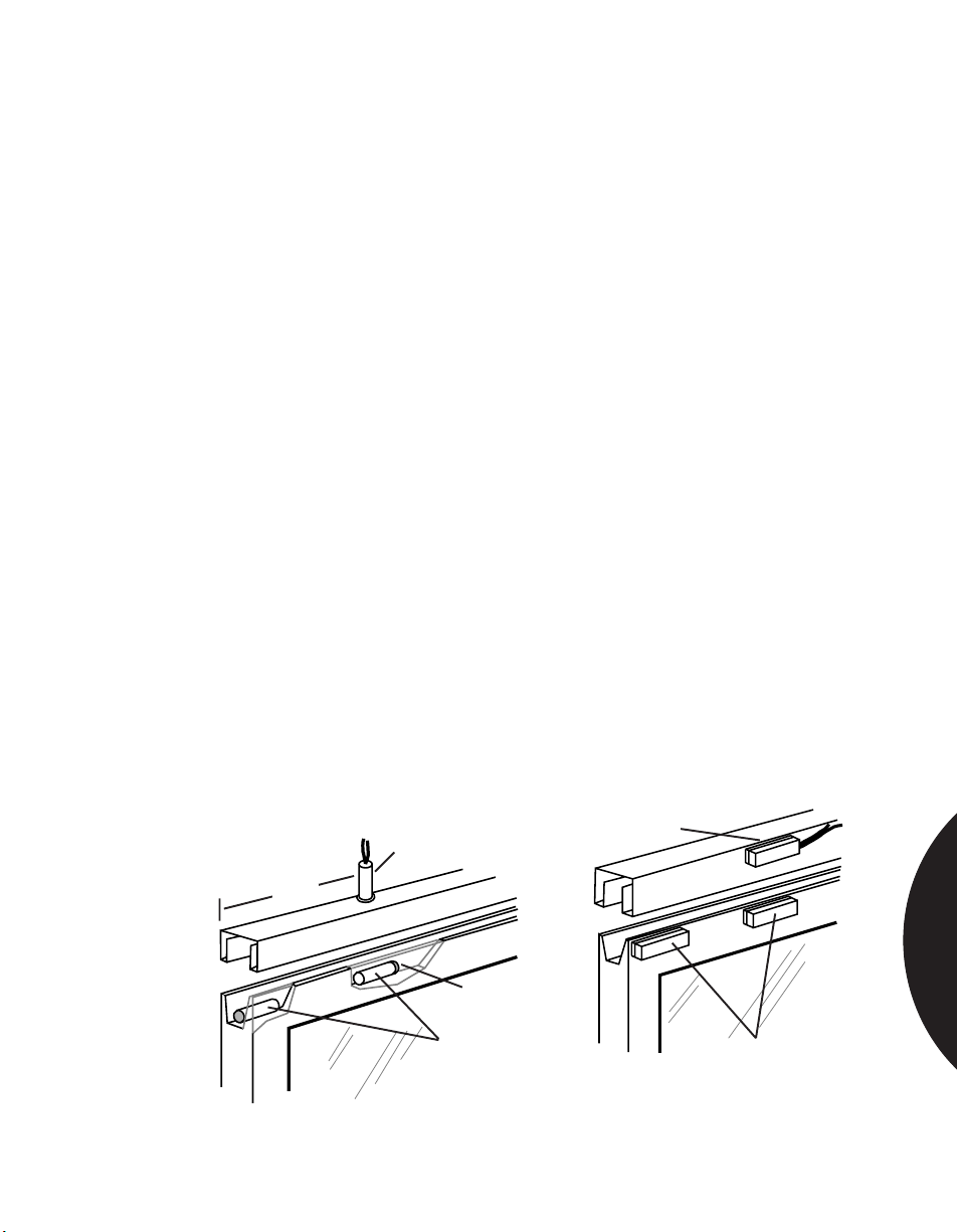
.........................................................................................................................................................................
Phone: 800.894.0412 - Fax: 888.723.4773 - Web: www.clrwtr.com - Email: [email protected]
Residential & Commercial Applications
VENTILATING WINDOWS WITH A
WIDE GAP MAGNET
APPLICATION
INISTALLATION
Venting sliding windows and doors using two magnets and one wide gap switch.
It is possible to obtain up to 5" (12.7 cm) ventilation with a 1-1/2" (3.81 cm) gap
between the magnets and switch.
Select a wide gap recessed switch and an additional 3/8" (0.95 cm) diameter by
1-1/2" (3.81 cm) long magnet.
Remove window from frame (see Figure 1, page 93).
Slightly over-drill vertical hole for switch in top of frame, about 5-1/2" (14 cm) from
edge of frame. Coat switch with RTV mounting compound and insert in hole.
Mount magnets on inside of upper window channel toward top of channel with
RTV mounting compound (Figure 1). Locate one magnet at edge of channel, red
end toward edge of window. Locate other magnet with non-red end under switch
— red end pointing away from other magnet.
After RTV sets (about 15 minutes), reinsert window in frame.
Attach ohmmeter to leads and test for proper switch operation. If switch “drops
out” anywhere within ventilation range, move inside magnet (and switch) closer to
outside edge of door or window.
Connect to alarm loop.
Instruct customer on proper use of ventilation feature. If necessary, add a window
stop or mark maximum permissible opening to prevent false alarms.
Note: Sliding windows can also be vented using a surface mounted switch and
magnet. Also, 1275W series switches can be used for this application.
RECOMMENDED
PRODUCTS
1035W, 1145W, RTV 1905
Switch
5 1/2”
Figure 1. Recessed Installation
Red End
Magnets
Switch
Figure 2. Surface Mount
Installation
Magnets
MAGNETIC CONTACTS
3.24
Page 88
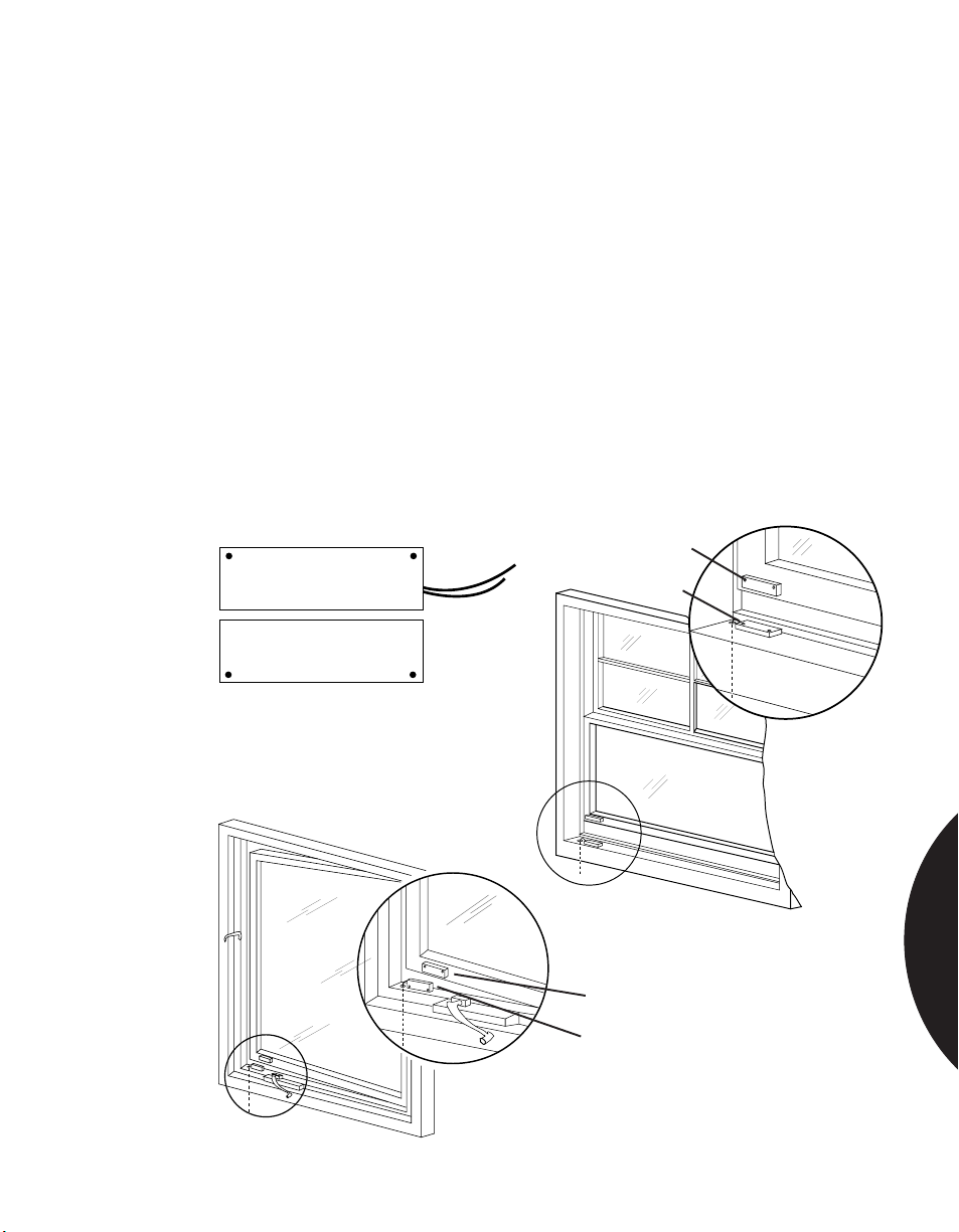
.........................................................................................................................................................................
Phone: 800.894.0412 - Fax: 888.723.4773 - Web: www.clrwtr.com - Email: [email protected]
Residential & Commercial Applications
PROTECTING THIN FRAME WINDOWS
APPLICATION
INSTALLATION
RECOMMENDED
PRODUCTS
Securing Pella or sliding aluminum windows or doors which have thin window
frames and limited space for mounting the switch. Sentrol’s 1145-W ultraminiature surface-mount magnetic contact, with regular or wide gap operating
distance, is ideal for this application.
Determine best position for switch and magnet. Magnet will be mounted on frame
of glass.
Switch and magnet are mounted with very high bonding tape, silicon glue or brass
brads, depending upon the frame material.
Clean surface with alcohol for good adhesion.
For wide gap versions, switch and magnet must be mounted with mounting holes
to the “outside” in “four-corners” position (Figure 1), with Sentrol logo on switch
and magnet reading from left to right. This assures proper polarity. Wide gap
operating distance is 3/4" (1.9 cm) for 1145W model.
1145W
Magnet
SENTROL
Switch
SENTROL
Figure 1.
MAGNETIC CONTACTS
Figure 2. Crank-Out Window
Magnet
Switch
Figure 3. Double-Hung Window
3.25
Page 89
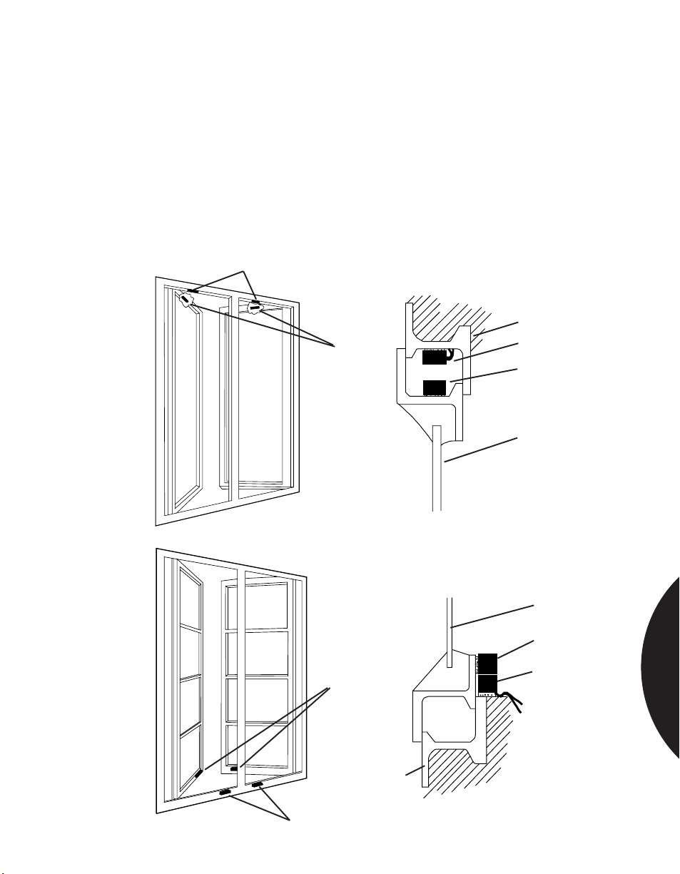
.........................................................................................................................................................................
Phone: 800.894.0412 - Fax: 888.723.4773 - Web: www.clrwtr.com - Email: [email protected]
Residential & Commercial Applications
PROTECTING THIN STEEL FRAME WINDOWS
APPLICATION
INSTALLATION
RECOMMENDED
PRODUCTS
Installing magnetic contacts on windows with thin steel frames when a thin section
of steel presents drilling and tapping difficulties.
Use an adhesive-mount switch. Clean frame with alcohol for good adhesion. Two
methods are shown — one recessed, one surface mount. Drill holes to conceal
wiring if desired.
Note: The 1145W miniature contact is ideal for this application.
1035W, 1145W
Switches
Frame
Magnets
Switch
Magnet
Window
MAGNETIC CONTACTS
Window
Magnet
Magnets
Frame
Switches
Switch
3.26
Page 90
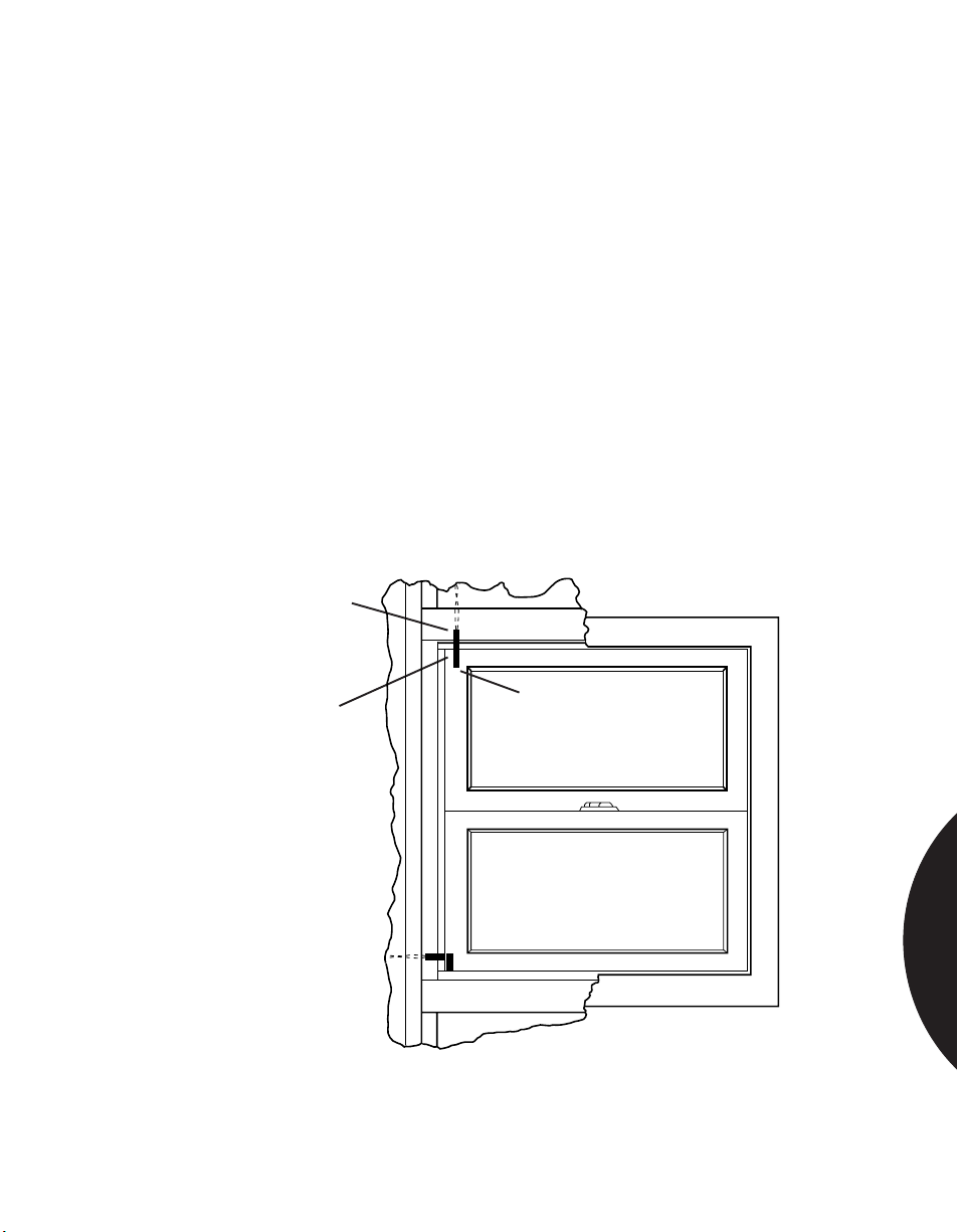
.........................................................................................................................................................................
Phone: 800.894.0412 - Fax: 888.723.4773 - Web: www.clrwtr.com - Email: [email protected]
Residential & Commercial Applications
PROTECTING DOUBLE HUNG WINDOWS
APPLICATION 1
INSTALLATION
RECOMMENDED
PRODUCTS
Recessed Installation in Top of Upper Window and
Bottom of Lower Window
Protecting double hung windows with recessed or surface-mounted magnetic
contacts with regular or wide gap switches.
Select position of magnet in window frame. Select position of switch in head or
sill. Slightly over-drill holes for switch and magnet. Coat switch and magnet with
RTV mounting compound. Insert switch and magnet in holes.
Note: Wide gap switches are polarity sensitive. If switch uses bare magnet,
observe correct polarity by mounting magnet with red end away from switch.
Attach ohmmeter to leads and check for proper operation.
Connect switch to loop.
If desired, cover switch and magnet with wood filler to camouflage and to improve
appearance.
1015, 1055, 1059, 1065, 1075, 1125W, 1275W, RTV 1905
End-to-End Recessed
Switch
Red End
Recessed Magnet
(If Wide Gap)
MAGNETIC CONTACTS
3.27
Page 91
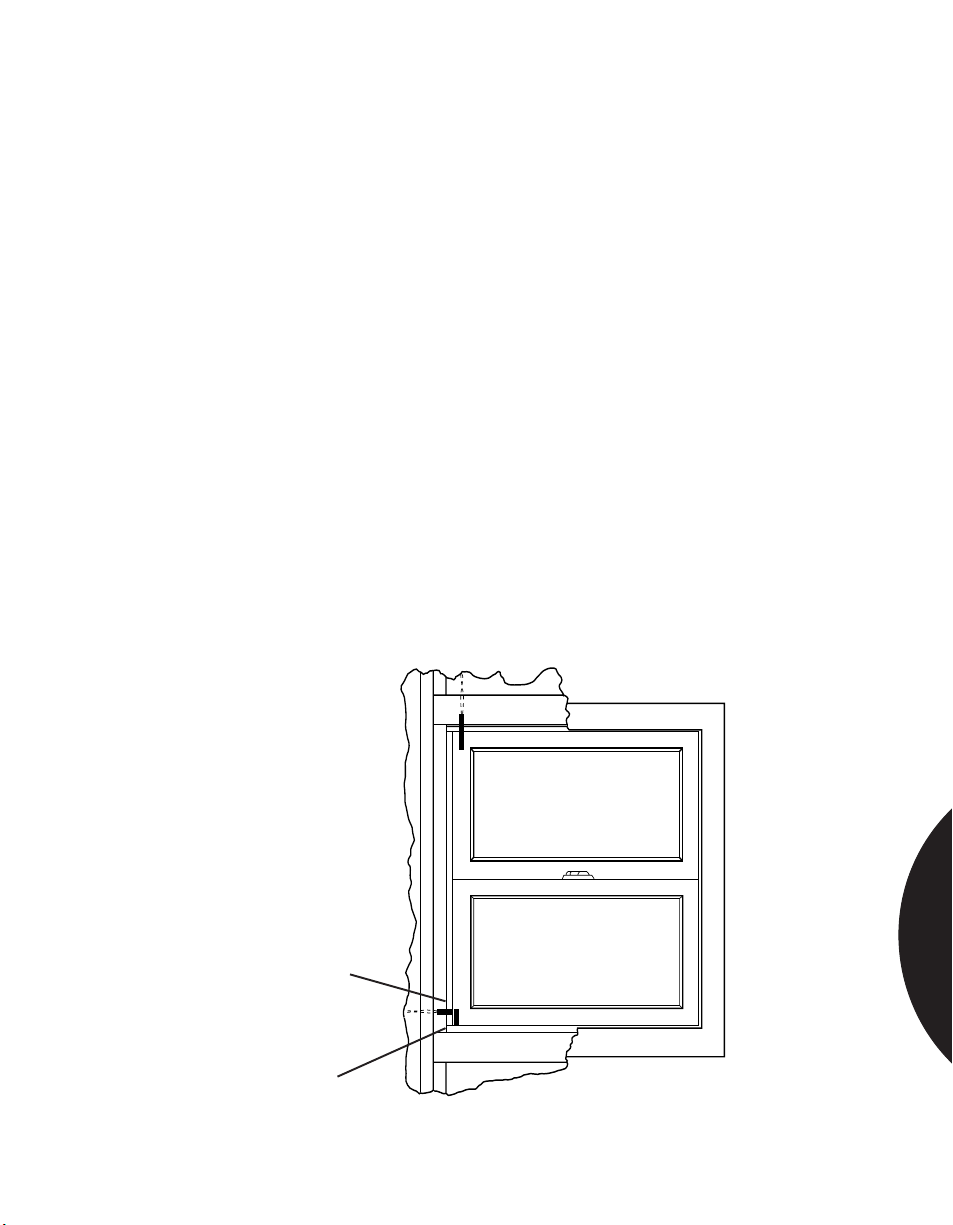
.........................................................................................................................................................................
Phone: 800.894.0412 - Fax: 888.723.4773 - Web: www.clrwtr.com - Email: [email protected]
Residential & Commercial Applications
PROTECTING DOUBLE HUNG WINDOWS
APPLICATION 2
INSTALLATION
RECOMMENDED
PRODUCTS
Recessed Installation in Sides of Window
This method of protecting double hung windows is recommended only when
walls are open and readily accessible for running wires (i.e., during construction or
remodeling). A finished wall will make this a very difficult job, requiring
extremely awkward “fishing.”
Requires perpendicular mounting of switch and magnet, and may require a wide
gap between switch and magnet.
Drill vertical hole in window frame for magnet. Coat magnet with RTV mounting
compound and insert in hole.
Pick position for switch. This will be determined by two requirements:
1) Magnet must not be centered under switch. End of switch must be opposite
the end of magnet (perpendicular) as shown.
2) If wide gap switch is used, observe correct polarity by mounting magnet with
red end away from the switch end with wires.
Drill hole for switch and insert switch.
Attach ohmmeter to leads. Close windows and test for correct operation.
Connect switch to loop.
1055, 1059, 1065, 1075, or same models in wide gap, RTV 1905
MAGNETIC CONTACTS
Perpendicular
Recessed Switch
Recessed Magnet
3.28
Page 92
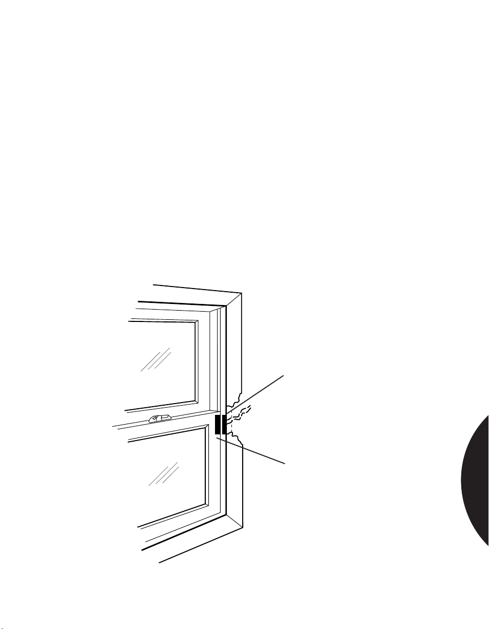
.........................................................................................................................................................................
Phone: 800.894.0412 - Fax: 888.723.4773 - Web: www.clrwtr.com - Email: [email protected]
Residential & Commercial Applications
PROTECTING DOUBLE HUNG WINDOWS
APPLICATION 3
INSTALLATION
RECOMMENDED
PRODUCTS
Surface Installation on Upper and Lower Windows
Select appropriate surface mount switch. Mount switch on head, sill, or jamb in
desired position.
Mount magnet on window, directly opposite switch when window is closed. If
using switch with self-adhesive, clean surface with alcohol before mounting to
assure good bond.
Note: If wide gap switch is used, be certain to align labels on switch and magnet
so they read in the same direction (switch is polarity sensitive).
Attach ohmmeter to leads and test for correct operation.
Connect switch to alarm loop.
1032, 1035, 1045T, 1082, 1085, 1085T, or same models in wide gap
End-to-End Recessed
Switch
MAGNETIC CONTACTS
Recessed Magnet
3.29
Page 93

.........................................................................................................................................................................
Phone: 800.894.0412 - Fax: 888.723.4773 - Web: www.clrwtr.com - Email: [email protected]
Residential & Commercial Applications
PROTECTING PELLA CASEMENT
OR AWNING WINDOWS
APPLICATION 1
INSTALLATION
Surface Mount Contacts
The miniature size and large number of mounting options available for the Sentrol
1025 series make these switches ideal for protecting Pella casement windows. The
switch and magnet are concealed when the window is closed. Concealed surface
mounting offers benefits over recessed mounting because the construction of
these windows makes recess mounting difficult without breaking the glass.
Important: Pella recommends against mounting switches in sills due to possible
damage from water. If you must drill into the sill, make sure you provide a solid,
tight seal using RTV compound.
Select position of switch and magnet. If ventilation is desired, locate near hinged
side of window.
Drill holes for wires. Slant back at 15˚ to 30˚ to make sure wire will go inside wall
(Figures 1 & 2).
If 1025W wide gap is used, align so that hinge ends of switch and magnet are next
to each other (switch is sensitive to polarity of magnet).
Note: There is nominally 1/2" (1.27 cm) clearance at the widest point between the
bottom or top of window and the sill. Since the widths of the 1025 switch and magnet
with flanges attached are 1/4" (0.635 cm) each, it may be necessary to remove one or
both flanges to allow sufficient clearance to mount switch and magnet.
MOUNTING
METHOD 1:
Mounting with Screws or Nails
• Open switch or magnet so flange is perpendicular to body of switch or magnet.
• Attach with nails or screws through flange.
• Swing body of switch or magnet into flange. Press until body catches on flange.
MOUNTING
METHOD 2:
Mounting with Self-adhesive Tape
• Cut off flange at hinge with diagonal cutters.
• Clean back of switch, magnet, and surfaces where switch and magnet will be
attached with alcohol. Remove backing from tape and attach tape to switch or
magnet, then attach switch or magnet to cleaned surface.
MOUNTING
METHOD 3:
Mounting with Glue, Epoxy, or RTV Mounting Compound
• Cut off flange at hinge with diagonal cutters.
• Attach switch or magnet to surface with glue, epoxy, or RTV mounting
compound.
Attach ohmmeter to switch leads and check for proper operation of switch.
Connect switch to alarm loop.
RECOMMENDED
PRODUCT
1025, RTV 1905
MAGNETIC CONTACTS
3.30
Page 94
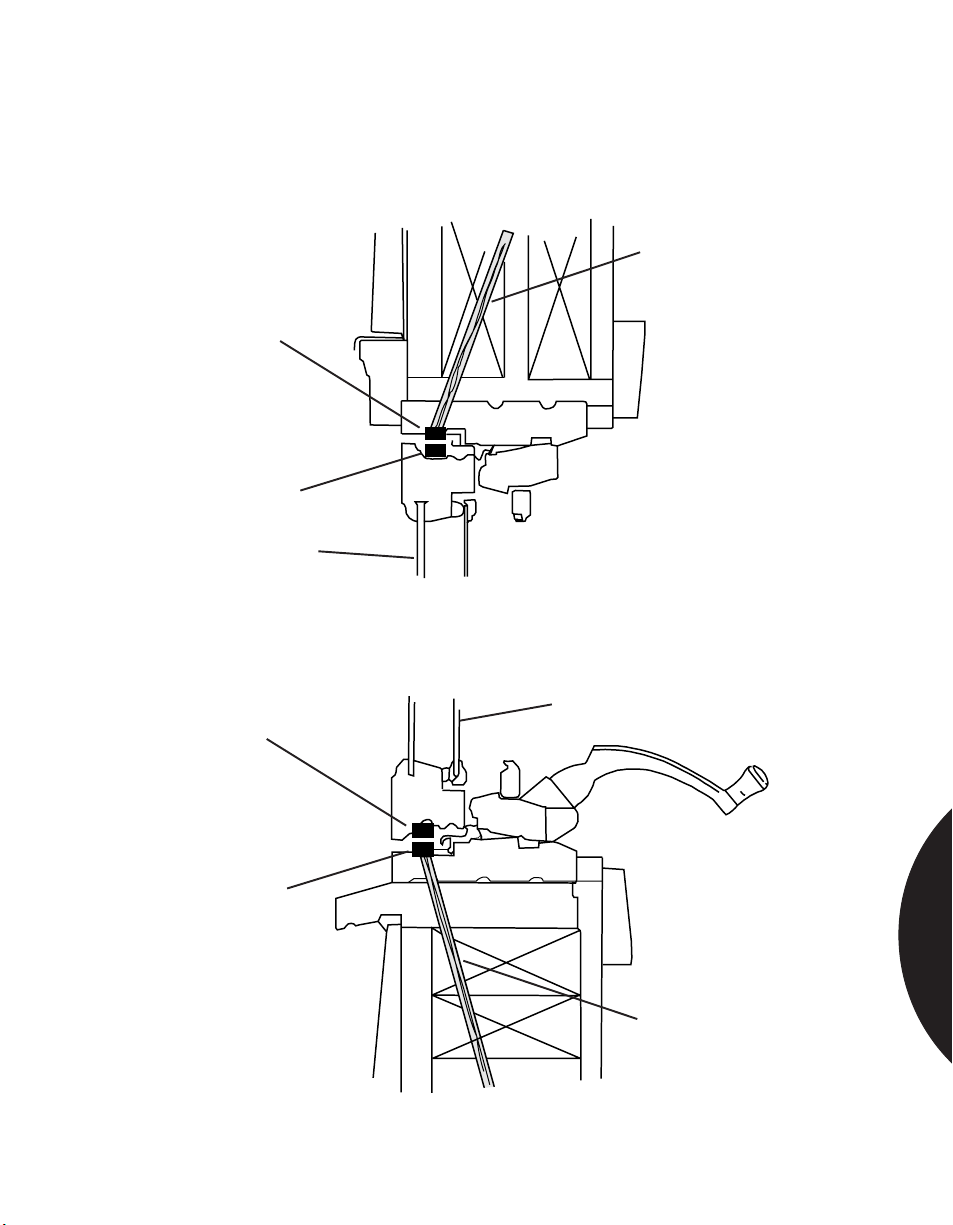
.........................................................................................................................................................................
Phone: 800.894.0412 - Fax: 888.723.4773 - Web: www.clrwtr.com - Email: [email protected]
Residential & Commercial Applications
PROTECTING PELLA CASEMENT
OR AWNING WINDOWS
Wire access hole.
Drill at 15°–30° from
vertical.
Switch
Magnet
Window
Figure 1. (Top of Window)
Window
Magnet
Switch
Wire access hole.
Drill at 15°–30° from
vertical.
Figure 2. (Bottom of Window)
MAGNETIC CONTACTS
3.31
Page 95
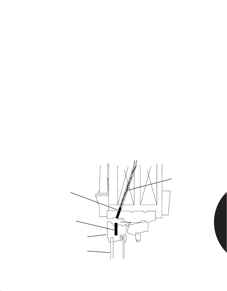
.........................................................................................................................................................................
Phone: 800.894.0412 - Fax: 888.723.4773 - Web: www.clrwtr.com - Email: [email protected]
Residential & Commercial Applications
PROTECTING PELLA CASEMENT
OR AWNING WINDOWS
APPLICATION 2
INSTALLATION
RECOMMENDED
PRODUCTS
Recessed Contacts
Pella casement and awning windows may have two separate pieces of glass or one
Thermopane. It is very important, therefore, to take extra care when drilling the
mounting holes to avoid the glass.
Important: Pella recommends against mounting switches in sills due to possible
damage from water. If you must drill into the sill, make sure you provide a solid,
tight seal using RTV compound.
Select position of switch in top of window frame if wires will run through attic, or
in bottom of window if wires will run through basement.
Drill 1/4" (0.635 cm) diameter x 1-1/4" (3.175 cm) deep hole in window sash.
Insert magnet. If using wide gap switch, insert magnet with red end away from the
switch end without wires.
Drill 1/4" diameter hole in frame at approximately 15˚ toward inside of wall. Align
switch hole center to within 1/4" of center of magnet.
Insert switch (1055W placed close to the pivot point will allow for some
ventilation).
Test circuit, and glue switch and magnet in place.
1015, 1015W, 1055, 1055W, 1125W
Wire access hole.
Drill at 15°–30° from
vertical.
Switch
Magnet
Window Sash
Window
MAGNETIC CONTACTS
3.32
Page 96
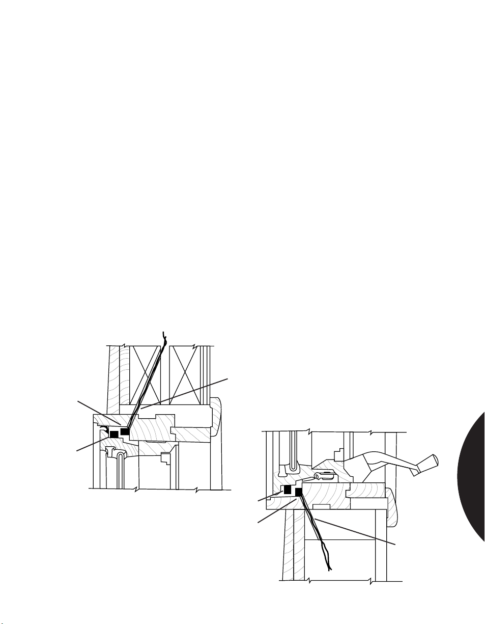
.........................................................................................................................................................................
Phone: 800.894.0412 - Fax: 888.723.4773 - Web: www.clrwtr.com - Email: [email protected]
Residential & Commercial Applications
PROTECTING ANDERSON CASEMENT WINDOWS
APPLICATION 1
INSTALLATION
RECOMMENDED
PRODUCTS
Switch
Surface Mount Contacts
Using surface mount contacts, the switch and magnet are both concealed when the
window is closed. Use off-white, white or mahogany brown units to match plastic
cover on the window.
Important: Anderson recommends against mounting switches in sills due to
possible damage from water. If you must drill into the sill, make sure you provide a
solid, tight seal using RTV compound.
Select position of switch and magnet. Ventilation may be achieved with the use of
a wide gap switch placed on the top of the window near the hinged side.
Drill hole for wires. Slant back 15˚ to 30˚ to make sure wires go inside wall. Drill at
back of window frame as shown.
Clean surfaces with alcohol to remove dirt, grease and moisture.
Peel paper from back of switch and install as shown, or screw in place (depending
on switch used).
Peel paper from back of magnet. Install on sash frame with Sentrol name reading
the same direction as on switch.
Close window and test circuit.
1125, 1035, RTV 1905
Wire access hole.
Drill at 15°–30° from
vertical.
MAGNETIC CONTACTS
Magnet
Figure 1. (Top of Window)
Magnet
Switch
Figure 2 (Bottom of Window)
Wire access
hole.
Drill at 15°–30°
from vertical.
3.33
Page 97
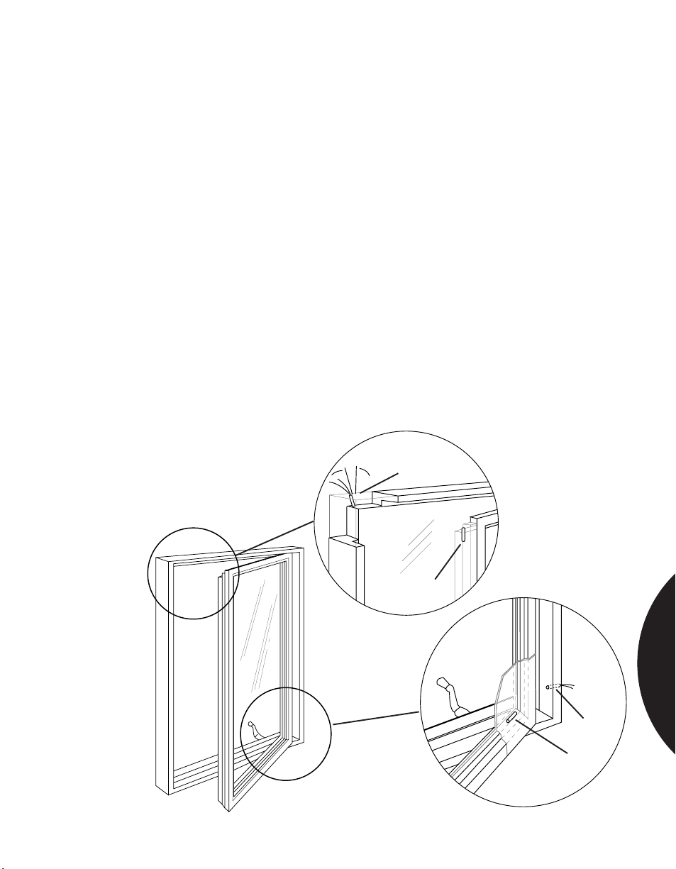
.........................................................................................................................................................................
Phone: 800.894.0412 - Fax: 888.723.4773 - Web: www.clrwtr.com - Email: [email protected]
Residential & Commercial Applications
PROTECTING ANDERSON CASEMENT WINDOWS
APPLICATION 2
INSTALLATION
RECOMMENDED
PRODUCTS
Recessed Contacts
Two methods for protecting Anderson casement windows are shown here. Figure 1
shows the standard method. Figure 2 shows the method used if ventilation is
required. It is important to note that both methods require the magnet be placed
in the sash on the step closest to the inside of the window.
Important: Anderson recommends against mounting switches in sills due to
possible damage from water. If you must drill into the sill, make sure you provide a
solid, tight seal using RTV compound.
Install magnet in sash on the step closest to the inside. Drill hole 1/4" (0.635 cm)
diameter x 1-1/4" (3.175 cm) deep. This step has a cross section of about 1/2" x 1/2"
(1.27 cm x 1.27 cm) and will hold the 1/4" diameter magnet by centering the hole
in the section.
Drill hole for switch opposite magnet. Angle this hole back toward inside of wall
about 15˚.
Install switch and test.
Cover ends of switch and magnet with silicone rubber to protect from weather.
1015, 1015W, 1055, 1055W, 1125W, RTV 1905
15°
Switch
MAGNETIC CONTACTS
Magnet
Figure 1
Magnet
Figure 2
Switch
3.34
Page 98
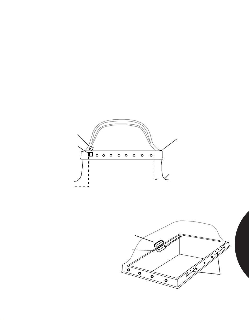
.........................................................................................................................................................................
Phone: 800.894.0412 - Fax: 888.723.4773 - Web: www.clrwtr.com - Email: [email protected]
Residential & Commercial Applications
PROTECTING ROOF ENTRY—
PROTECTING HINGED SKYLIGHTS
APPLICATION
INSTALLATION
RECOMMENDED
PRODUCTS
Protecting against unwanted intrusion through a hinged skylight using surfacemount magnetic contacts.
Select location for switch and magnet on side opposite the hinges. Mount switch
on frame and magnet on skylight. Observe gap distance tolerances. You may have
to use spacers to achieve proper alignment.
If skylight has steel frame, gap distance is generally reduced by half. In this case,
use wide gap switches. Mount switch and magnet so Sentrol logo on both reads in
the same direction (switch is polarity sensitive).
Test for proper operation.
1032, 1035, 1085, 1145, 1032W, 1035W, 1085W, 1085TW, 1085T
Magnet
Hinge
Switch
Roof
Figure 1
Magnet
Switch
Figure 2
MAGNETIC CONTACTS
Hinges
3.35
Page 99
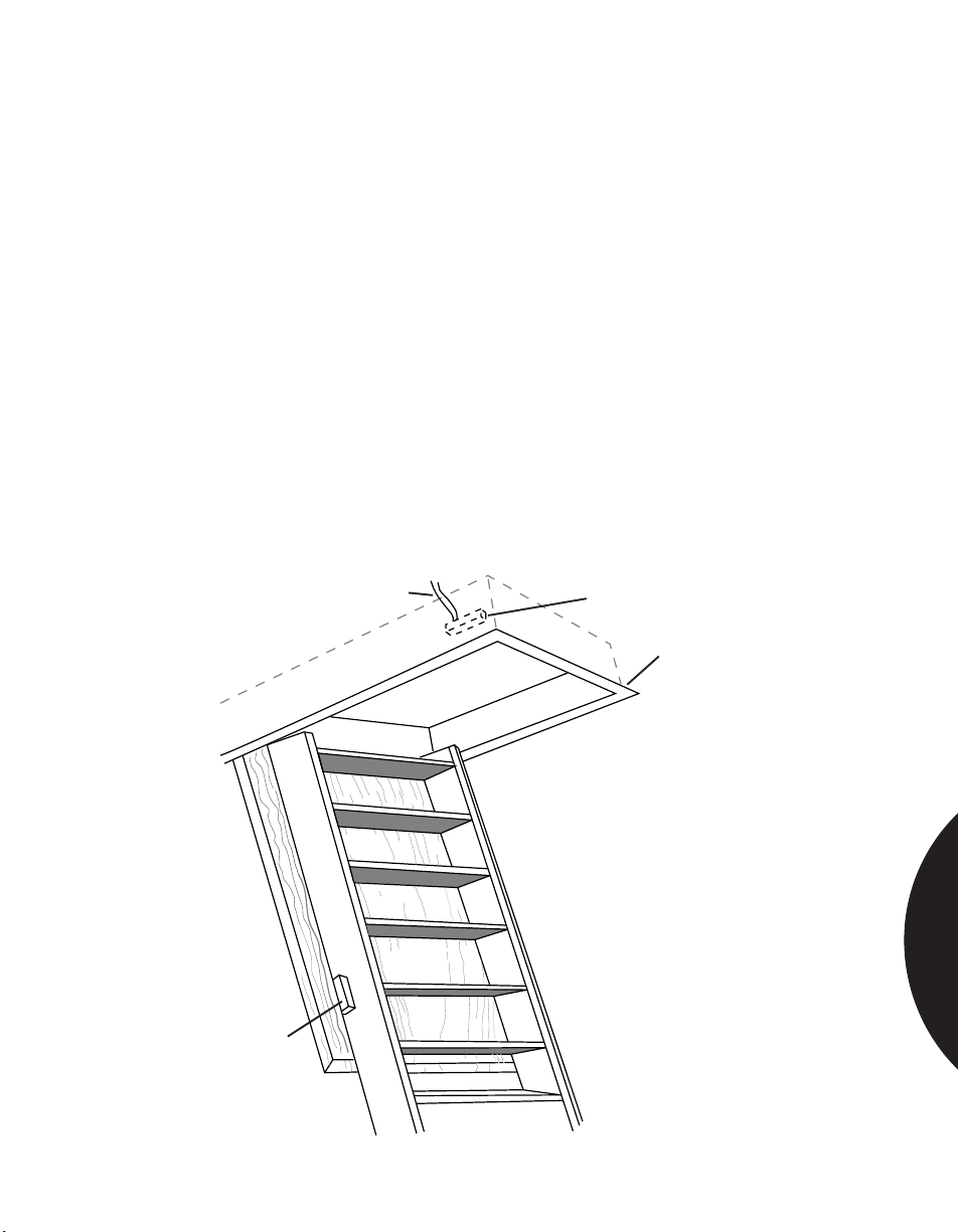
.........................................................................................................................................................................
Phone: 800.894.0412 - Fax: 888.723.4773 - Web: www.clrwtr.com - Email: [email protected]
Residential & Commercial Applications
PROTECTING ROOF ENTRY—
PROTECTING DROP-DOWN STAIRS—ATTIC ENTRY
APPLICATION
INSTALLATION
RECOMMENDED
PRODUCTS
Often the entry door from the garage to the house will be alarmed and the garage
door will be left unsecured. An intruder can gain access to the garage door, enter
the attic via the drop-down stairway, cut a hole through the ceiling between the
joists, and drop into the house, all without triggering the alarm.
Position switch on stairway frame, and magnet on drop-down portion of the
stairway. There must be no interference to stairway mechanism from switch or
magnet.
Permanently attach switch to frame, and temporarily attach magnet to stairway
with masking tape. Connect ohmmeter to switch lead, close stairway, and test for
continuity.
Permanently attach magnet to stairway. Connect switch leads to alarm loop.
Note: A Sentrol surface mount switch may be used. For high-security and wide
gap switches, labels on switch and magnet must read in the same direction. Also,
observe minimum and maximum gap distances for high-security switches.
1035W, 1045T, 1082, 1085W, 1085TW, 2500 or H series
To Alarm Loop
Switch
Frame
Magnet
MAGNETIC CONTACTS
3.36
Page 100
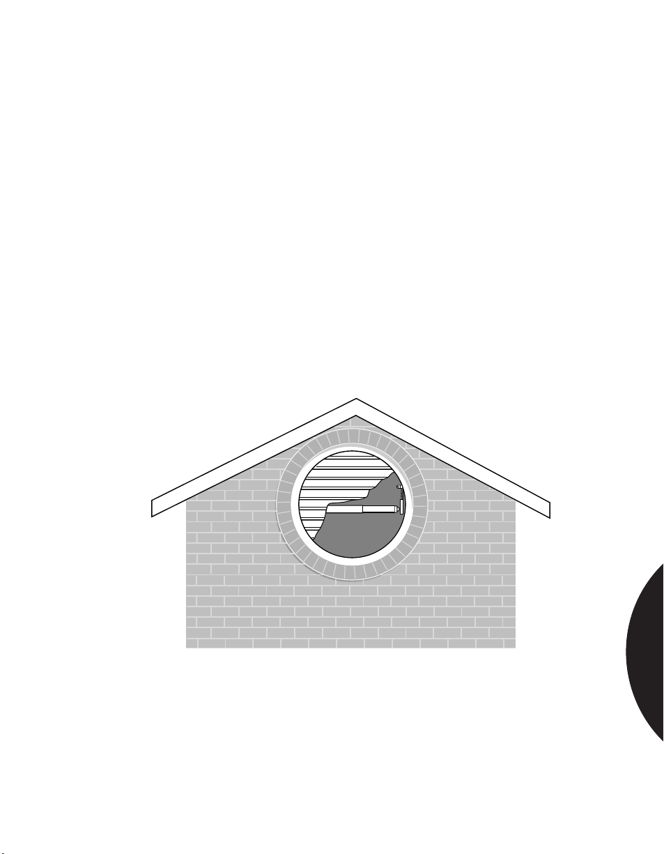
.........................................................................................................................................................................
Phone: 800.894.0412 - Fax: 888.723.4773 - Web: www.clrwtr.com - Email: [email protected]
Residential & Commercial Applications
APPLICATION
INSTALLATION
RECOMMENDED
PRODUCTS
PROTECTING ROOF ENTRY
USING BARRIER BARS
Protect against unwanted intrusion through a hinged skylight, attic vents,
basement windows, or any other oddly shaped opening, with pressure switch
activated, spring loaded Barrier Bars.
Barrier Bars can be surface or frame mounted in wired or wireless systems. Springloaded assembly snaps into place with no screws or drilling. Self-adhesive, epoxybased switch adheres to brick or cement surfaces, forming a strong, permanent
bond.
Select location for switch so that bar crosses center of opening. Remove adhesive
backing and press switch in place. Run cable to switch and attach to terminals.
Snap bar into place, using spacer for openings wider than 32" (81.3 cm).
Test for proper operation.
BB-1GS Pressure-Sensitive, BB-2 Mercury Tilt Switch, AMB-1 bracket, OVB-1
vertical bars
®
MAGNETIC CONTACTS
3.37
 Loading...