

CLR Jackson 400 Series, 450 Series, 451 series Installation Instructions Manual
INSTALLATION INSTRUCTIONS
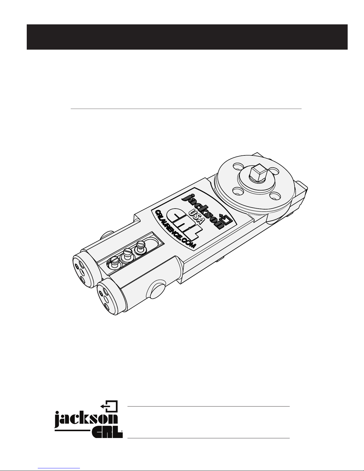
CRL JACKSON OVERHEAD
CONCEALED DOOR CLOSER
CENTER HUNG AND OFFSET
crlaurence.com
HB
C
H
C
L
Phone: (800) 421-6144 • Fax: (800) 262-3299
crlaurence.com • usalum.com • crl-arch.com
11M0193
CRL JACKSON OVERHEAD CONCEALED DOOR CLOSER
PRODUCT DESCRIPTION
Jackson Overhead Concealed Door Closers (OHC) are available from C.R. Laurence as closer bodies only or as standard
packages for center hung and offset door installations. The standard packages include the closer mechanism,
mounting brackets, arms, and pivots. OHC's are divided into three groups:
Standard OHC's (Brown) are offered with four (4) xed spring sizes for doors from 2'6" to 4'0" wide (see chart on page 14).
Other options include 90 degree and 105 degree hold open and non-hold open versions.
Grade 1 OHC's (Black) have been tested to ANSI Grade 1 Standards (2 million cycles). They feature a valve
adjustable hydraulic backcheck and are available in 90 degree and 105 degree hold open and non-hold open
models.
Adjustable OHC's (Blue) allow the opening spring force to be adjusted from 4.5 lbs. to 15 lbs. Adjustability
is especially useful when attempting to balance between stack pressure and ADA requirements. The standard
factory adjusted spring pressure is set to the size "Light Duty" and is intended for a 7'0" x 3'0" door. To increase
the spring force by one size, turn the adjustment screw four (4) turns clockwise. Adjustable OHC's are also available
in 90 degree and 105 degree hold open and non-hold open models.
All Jackson OHC's are non-handed, double-acting, and work with center hung and offset applications. Additionally, the body
size and mounting holes of standard and adjustable OHC's are identical and interchangeable with one another.
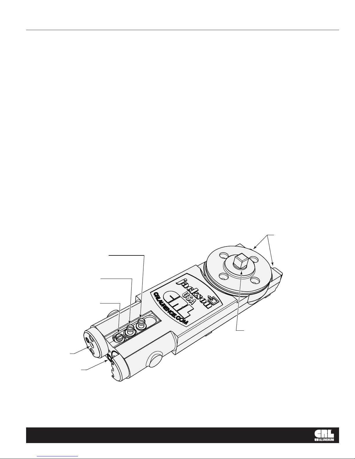
Optional Hydraulic
Backcheck Adjustment
(Black Models)
Closing Speed
Adjustment
(All Models)
Latching Speed
Adjustment
(All Models)
Bracket
Mounting Hole
Optional
Adjustable
Spring Power
(Blue Models)
Mounting Tabs
HB
C
H
C
L
Spindle
crlaurence.com | usalum.com
02

CRL JACKSON OVERHEAD CONCEALED DOOR CLOSER
CONTENTS
Jackson Overhead Concealed Door Closer ....................................... 04-06
Center Pivot Door Typical Installation Series 400, 450, and 451 ............................. 04
Instructions and Adjustments ..................................................... 05
Closer Located in Header ....................................................... 06
Frame Unit for Center-Hung Door with Overhead Concealed Door Closer ..........................07
Center Hung Installation, Door/Threshold Preparation .........................................08
Jackson Overhead Concealed Door Closer, Side Load Center Pivot Door ..........................09
Center-Hung Door Installation with a Side Load Top Arm ................................... 10 -11
Jackson Overhead Concealed Door Closer, End Load Center Pivot Door ...........................12
Center-Hung Installation ........................................................... 13-15
Top Arm Assemblies ............................................................... 13
Overhead Concealed Door Closers .................................................... 14
Pivots ...........................................................................15
Jackson Overhead Concealed Door Closer for Butt Hinge Door ......................................... 16
Jackson Overhead Concealed Door Closer for Offset Pivot Door, 90º Swing ........................ 17
Jackson Overhead Concealed Door Closer for Offset Pivot Door, 105º Swing .......................18
Offset Pivot Installation .............................................................. 19-20
Header for Jackson Overhead Concealed Door Closer With Offset Arm ...........................21
Jackson Overhead Concealed Door Closer for Offset Pivot Door .................................22
Offset Closer Arm Installation ......................................................... 23-24
Offset Arm/Channel Assemblies (Charts) ..................................................25
Center Pivot-Top Portion for Floor Mounted Closer ...........................................26
Frame Unit for Butt Hung Door with Surface Mounted Closer ................................ 27
crlaurence.com | usalum.com
03
CRL JACKSON OVERHEAD CONCEALED DOOR CLOSER
JACKSON OVERHEAD CONCEALED DOOR CLOSER
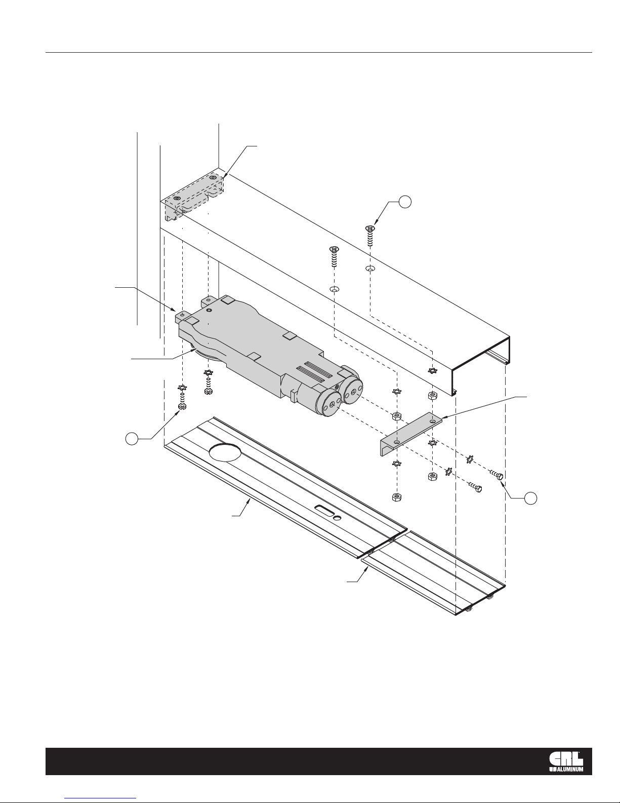
CENTER PIVOT DOOR TYPICAL INSTALLATION
SERIES 400, 450, AND 451 FABRICATED DOOR HEADER
Closer Mounting Bracket
(Bracket is also used as head to
jamb clip for frame fabrications)
*
3
(2) 1/4"-20 x 7/8" FH SMS
Mounting Lugs
Jackson Door Closer
See Page 5 for closer
adjustments
2
(2) 1/4"-20 x 5/8"
Round Head MS
Snap-In Cover Plate
(14" Long)
Snap-In Cover
Plate Extension
Closer mounting bracket is already installed (See FRAME UNITS installation instructions).
1. Mount angle bracket to door closer with (2) 1/4"-20 Hex Head Cap screw and (2) lock washers.
2. Install (2) 1/4"-20 x 5/8" Round Head MS into lugs of closer. Do not tighten screws.
3. Install (2) 1/4"-20 x 7/8" FH SMS* with (2) 1/4"-20 nuts and washers in header.
4. Insert closer lugs into mounting bracket slot at an angle and raise closer opposite end to align
mounting screws with angle bracket holes. Secure bracket to mounting screws using (2) nuts
and washers.
5. Tighten Round Head Screws.
6. Snap-In Cover Plate.
Angle Bracket
1
(2) 1/4"-20 x 1/2"
Hex Head Cap Screw
*For 2" x 4-1/2" header, longer screws are provided.
crlaurence.com | usalum.com
04
CRL JACKSON OVERHEAD CONCEALED DOOR CLOSER
JACKSON OVERHEAD CONCEALED DOOR CLOSER
INSTRUCTIONS AND ADJUSTMENTS
IMPORTANT: PLEASE READ BEFORE PROCEEDING. Observe all safety warnings. Always wear proper eye
protection and appropriate safety equipment. Always place a safety block between the door and the jamb to prevent the
door from closing while making adjustments. The closer contains springs compressed under high load and has no user
serviceable internal components. Do not attempt to remove the covers or otherwise open the closer in any manner.
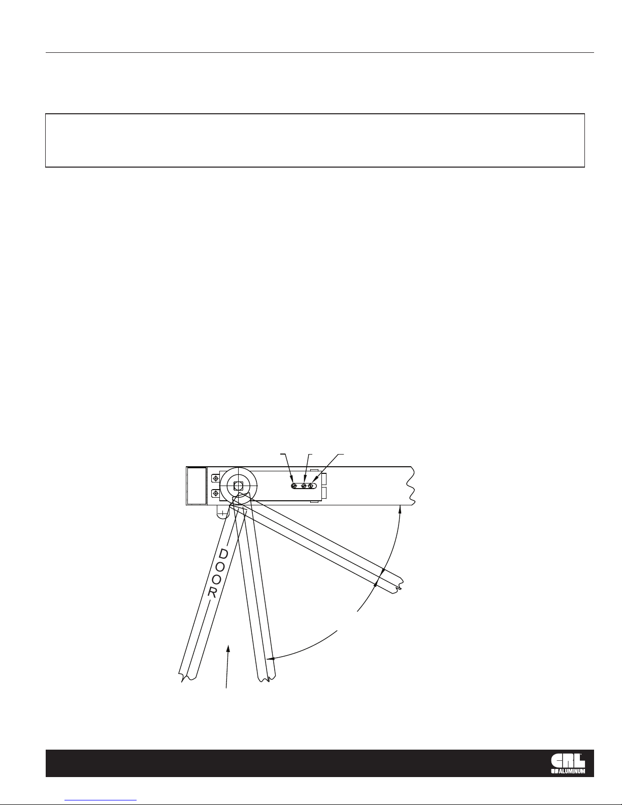
The closer has been fully tested and adjusted at the factory. The closing and latching speeds have been pre-set to achieve a
6 to 8 second closing cycle. The optional hydraulic backcheck has not been factory pre-set. After installation, cycle the door
10 or more times from the maximum open position to the full closed position prior to making nal adjustments.
To increase either the closing or latching speeds, turn the appropriate adjustment valve counter-clockwise. To decrease either
the closing or latching speeds, turn the appropriate adjustment valve clockwise. Set the latching speed (Valve "L") rst, then
set the closing speed (Valve "C"). Check and readjust if necessary.
Hydraulic Backcheck (if so equipped) turn the adjustment valve clockwise to increase backcheck resistance which dampens
and slows the momentum of the door when opened with excessive force. Decrease resistance by turning the adjustment valve
counter-clockwise. The adjustment valve must not be adjusted so that the backcheck function is used as a rigid backstop.
Using the backcheck as a rigid backstop may cause damage to the closer or door.
Adjustable Spring Power (if so equipped) the adjustable spring power has been factory set to Size 2. To increase the
spring power, turn the adjuster clockwise. To decrease, turn the adjuster counter-clockwise. Typical door opening force adjusts
at the rate of approximately 1 pound of force (4.5 N) for each 3 to 4 revolutions of the adjuster.
IMPORTANT: Do not attempt to adjust the spring power with the door open beyond 20 degrees from fully closed.
WARNING: Neither the standard internal back stop nor the optional backcheck are to be used as the primary door stop.
An auxiliary oor or overhead door stop is always recommended to prevent structural interference and possible door and
closer damage.
C H"HBCH"
0°
DOOR
LATCHING AREA
"L" VALVE
80°
CLOSING AREA
"C" VALVE
HYDRAULIC BACKCHECK
VALVE AREA "HBCH"
crlaurence.com | usalum.com
05
CRL JACKSON OVERHEAD CONCEALED DOOR CLOSER
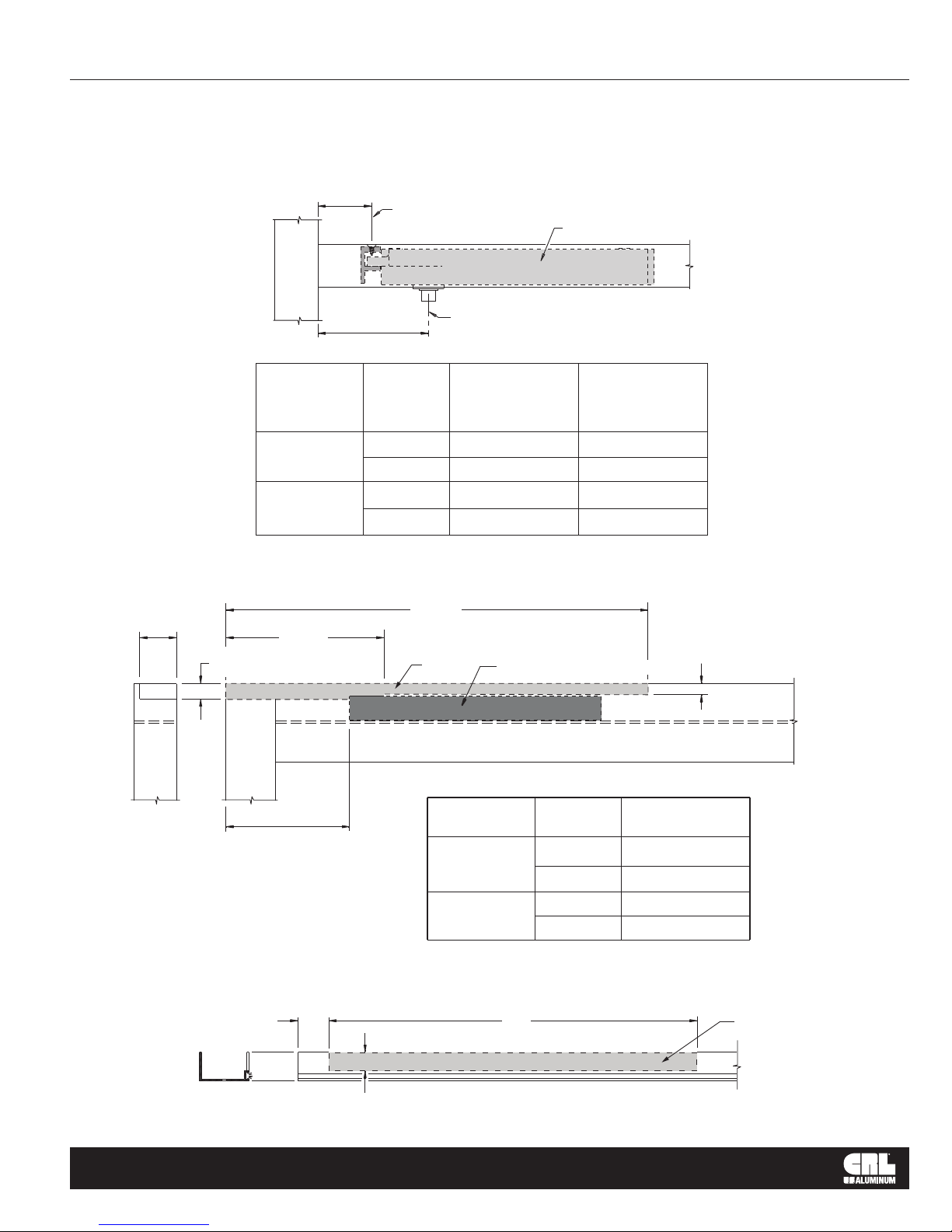
JACKSON OVERHEAD CONCEALED DOOR CLOSER
CLOSER LOCATED IN HEADER
1-1/2"
(38.1)
5/8"
(15.9)
"B"
DOOR TYPE
CENTER PIVOT
OFFSET PIVOT
(0P400)
BUTT HINGES
C of fasteners for closer mounting
L
VIEW OF HEADER AT CLOSER
C of Spindle
"A"
HOLD
OPEN
90º OR 105º
105º
90º
105º
90º
L
DIMENSION
"A"
2-3/4"
(69.9)
4-1/2"
(114.3)
3-3/4"
(95.3)
3-3/4"
(95.3)
2-7/8"
(73.0)
Jackson Closer
DIMENSION
(11.1)
2-3/16"
(55.6)
1-7/16"
(36.5)
1-7/16"
(36.5)
(14.3)
"B"
7/16"
9/16"
SLIDE CHANNEL LOCATION IN TOP DOOR RAIL FOR OFFSET ARM
17-3/16"
(436.6)
6-7/16"
(163.5)
Notch Out
Slide channel and spacer
(11.1)
7/16"
"C"
1-1/4"
(31.8)
DA201
crlaurence.com | usalum.com
TOP DOOR RAIL
DOOR VIEW FROM INSIDE
DOOR TYPE
OFFSET PIVOT
(0P400)
BUTT HINGES
HOLD
OPEN
90º
105º
90º
105º
OFFSET ARM COVER CHANNEL
RIGHT HAND SHOWN; LEFT HAND OPPOSITE
15"
(381.0)
3/4"
(19.1)
DIMENSION
"C"
4-15/16"
(125.4)
4-11/16"
(119.1)
4-1/16"
(103.2)
3-7/8"
(98.4)
Notch Out
NOT TO SCALE
06
CRL JACKSON OVERHEAD CONCEALED DOOR CLOSER
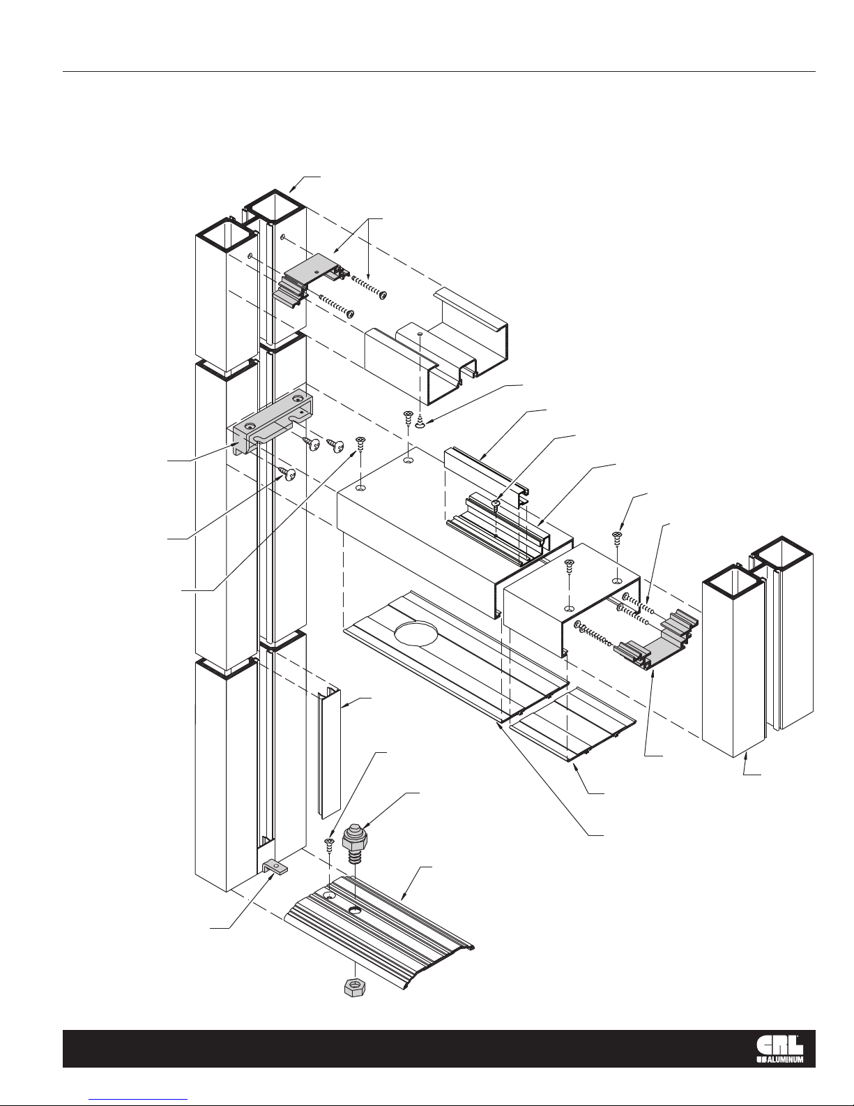
FRAME UNIT FOR CENTER-HUNG DOOR
WITH OVERHEAD CONCEALED DOOR CLOSER
JH475
APK402
Anchor Clip
with (2) 10X2PHPSMS
(1) ST240
#10 x 1/2" FH
M123 Glazing Stop
#6 x 3/8" PH at app.
Header and closer
mounting brackets
(included in closer
package). Header
bracket shown. Closer
bracket not shown.
(3) #8-32 x 1/2" PH
(Included in closer
package)
18" (457.2) O.C.
122 Glazing Sash and Glass Stop
(Not shown at Jamb for clarity)
(2) ST240 #10 x 1/2" FH
(4) #10 x 2 PHPSMS
(included in closer package)
(2) #10 x 3/8" FH SMS
(Included in closer
package)
Threshold clip
attach to filler
with #6 x 3/8" PH
P050 Filler
runs continuous
from header to
finish floor
(1) ST240
#10 x 1/2" FH
Bottom Pivot
TH250
P427 Snap-In
Cover Plate
Snap-In
Cover Plate
APK402
Anchor Clip
JH475
crlaurence.com | usalum.com
NOT TO SCALE
07
CRL JACKSON OVERHEAD CONCEALED DOOR CLOSER
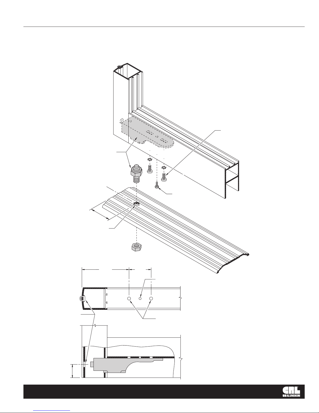
CENTER-HUNG INSTALLATION
DOOR/THRESHOLD PREPARATION
Cat. No. 20944
Threshold Mount
Bottom Pivot Set
(2) 1/4"-20 PH SMS
(with lock washers)
1/2" (12.7) Dia. hole
7/16" (11.1)
Dia. hole for
adjusting screw
C
L
3-3/4"
(95.3)
1-3/4"
(44.5)
(1) #10-32 PHSMS
(Install after door pivot
has been adjusted)
(1) hole for #10-32 PH SMS
(Install after door pivot
has been adjusted)
BOTTOM DOOR VIEW
Drill and Tap
(2) holes for 1/4"-20 PH SMS
1-1/16"
(26.9)
crlaurence.com | usalum.com
FRONT DOOR VIEW
NOT TO SCALE
08
CRL JACKSON OVERHEAD CONCEALED DOOR CLOSER
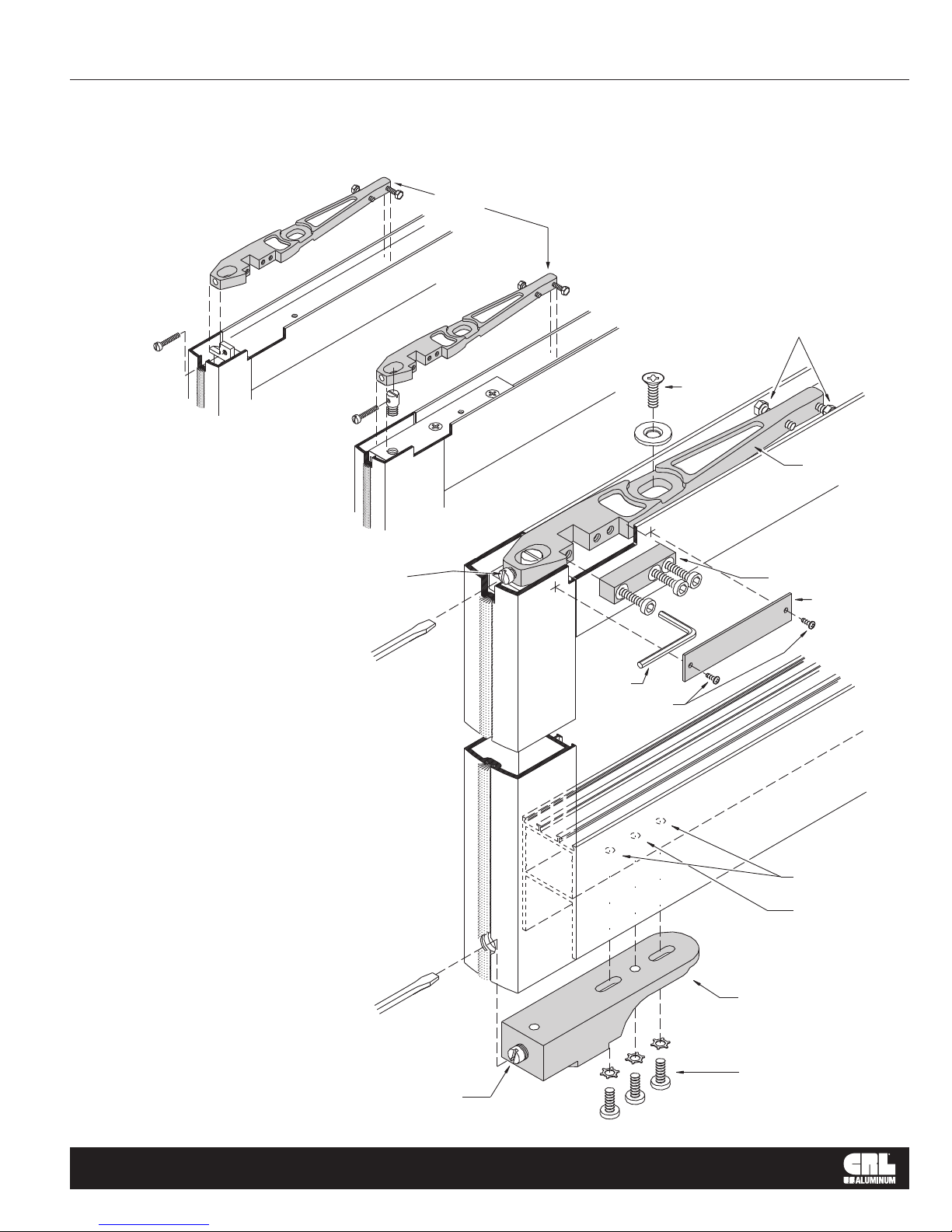
JACKSON OVERHEAD CONCEALED DOOR CLOSER
SIDE LOAD CENTER PIVOT DOOR
Side Load
Top Arm
DETAIL A
Holding
Screw
NARROW STILE
Centering Screws
Side Load
Top Arm
MEDIUM AND WIDE STILE
Top Centering
Adjusting screw
(Horizontal Adjustment)
1. Install top arm and door portion of bottom pivot
as shown in DETAIL A.
2. Position door upright in closed position on the
outside of frame.
3. Lift onto oor pivot and tilt to vertical.
4. Adjust top arm as required to receive closer spindle.
5. Install top clamping block see DETAIL B.
6. Drill two holes in top of door to attach cover plate
see DETAIL C.
If vertical adjustment is required, loosen or
tighten Pivot Adjusting Screw at bottom pivot
(door portion).
7. Adjust top arm centering screws to center door
in frame.
DETAIL B
Clamping Block
Cover Plate
DETAIL C
Tool
Mounting
screws
Holes by
U.S. Aluminum
Pinning hole
by installer
Door portion of
bottom pivot
crlaurence.com | usalum.com
Pivot Adjusting Screw
(vertical adjustment)
(3) 1/4"-20 RH MS
(with lock washers)
NOT TO SCALE
09
 Loading...