


INSTRUCTION MANUAL
PROFESSIONAL
HIGH RESOLUTION COLOR CAMERA
MODEL Z570
Please read this manual thoroughly before operation.

Safety Instructions
IMPORTANT: PLEASE READ THIS MANUAL CAREFULLY BEFORE INSTALLATION
AND RETAIN
Caution For Use
◈ Do not open the camera body.
◈ Do not insert object into the camera body.
◈ Do not touch with wet hands.
◈ Do not remove power cord while camera is in use.
◈ If signs of smoke or fire are detected, immediately remove main
Caution For Installation
◈ Camera requires AC to DC regulated adapter, DC12 V 250mA or AC to AC 24V
300mA.
◈ Apply a power supply after installation of camera.
◈ Do not point the camera toward a strong spot light or direct sun light.
◈ Do not install in areas of high humidity / heat or low temperature.
◈ Do not install in areas of high dust or particle pollution.
◈ Do not expose the camera to rain or moisture.
Package Includes
1 - High Resolution Color Camera
1 - L - Wrench
1 - Instruction Manual
1 - Warranty Resistration Card
1

Contents
◈ OSD CONTROL BUTTON TYPE ...................................................................................................
3
◈ SET UP MENU
.................................................................................................................................. 3
◈ MENU SET UP
.................................................................................................................................. 4
◈ LENS
.................................................................................................................................................. 5
◈ SHUTTER
.......................................................................................................................................... 6
◈ BLC
..................................................................................................................................................... 7
◈ AGC
.................................................................................................................................................. .10
◈ WHITE BALANCE ...........................................................................................................................
11
◈ FUNCTION
.......................................................................................................................................13
◈ CAMERA ID .....................................................................................................................................
14
◈ MIRROR ..........................................................................................................................................
15
◈ DAY & NIGHT ..................................................................................................................................
15
◈ MOTION
............................................................................................................................................16
◈ PRAVACY
.........................................................................................................................................18
◈ GAMMA ...........................................................................................................................................
.20
◈ LANGUAGE ....................................................................................................................................
20
2
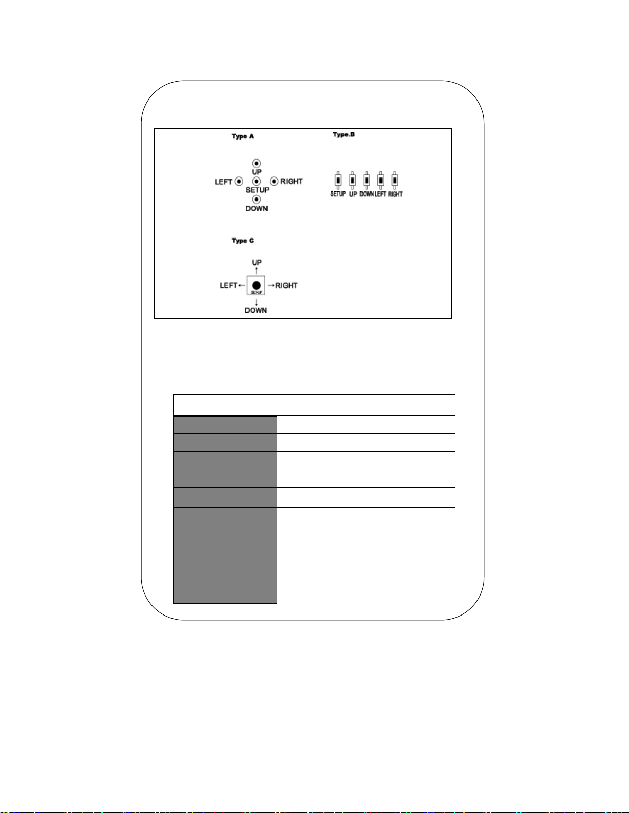
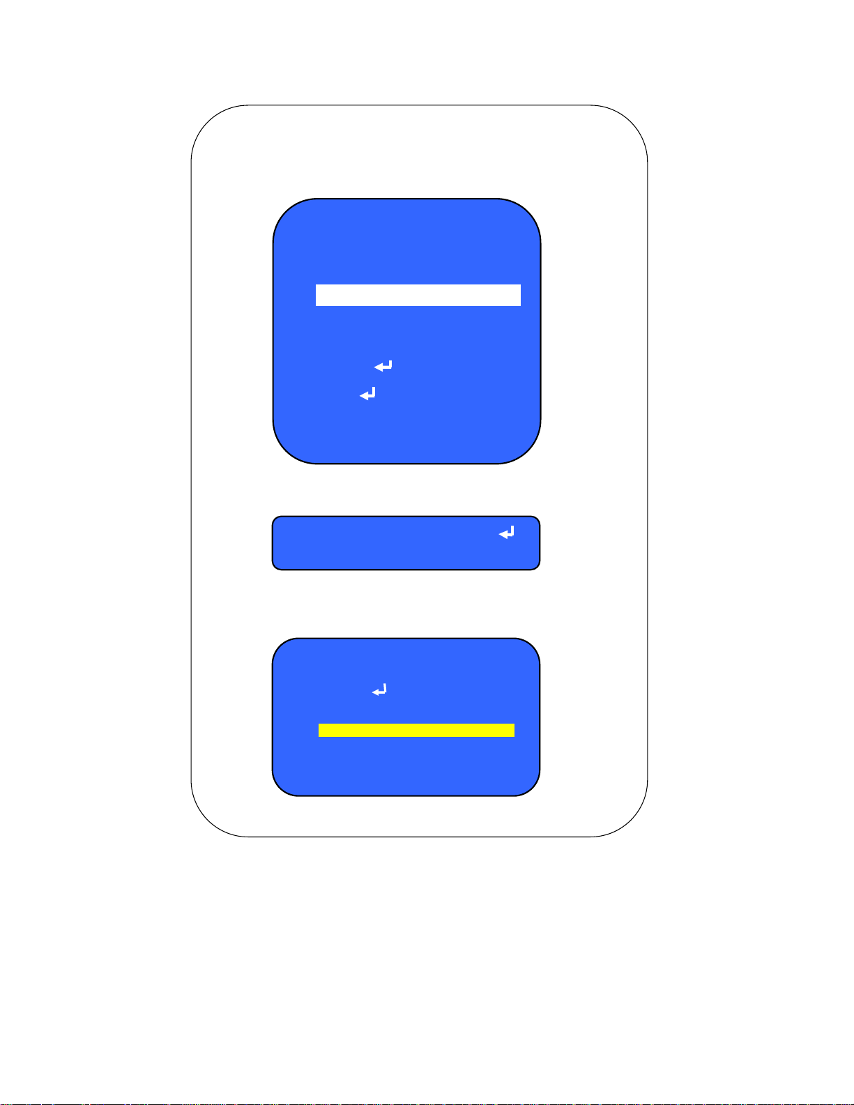
OSD Control Button Type
How To Operate the Camera Menu
◈ Setup Menu
SETUP
LENS
SHUTTER
BACKLIGHT(B L C)
A G C(Auto Gain
WHITE BAL.
FUNCTION
ADJUST
EXIT
●MANUAL ●DC ●VIDEO
●FIXED ●MANUAL ●AUTO ●F L K
●ON ●OFF
●ON ●OFF
●A T W ●A W B ●FIXED ●MANUAL
●RETURN ●CAMERA ID ●MIRROR
●DAY & NIGHT ●MOTION ●PRIVACY
●GAMMA ●LANGUAGE ●RESET
●ADJUST ●RETURN
3
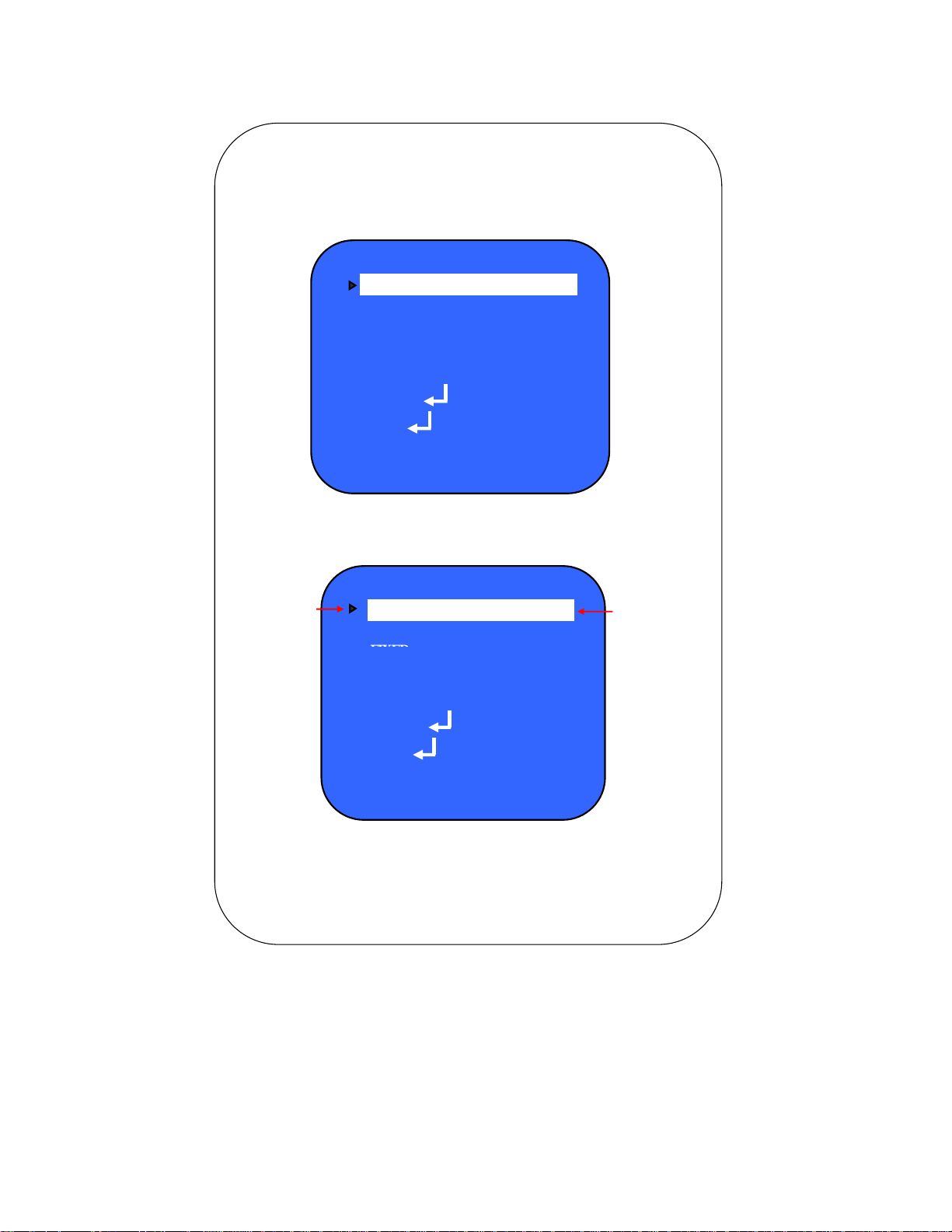
◈ Menu Set Up
1. Press the SET UP button
2. Setup menu will be displayed on the monitor
SETUP
LENS DC
SHUTTER FIXED
B L C ON
A G C ON
WHITE BAL A T W
FUNCTION
ADJUST
EXIT
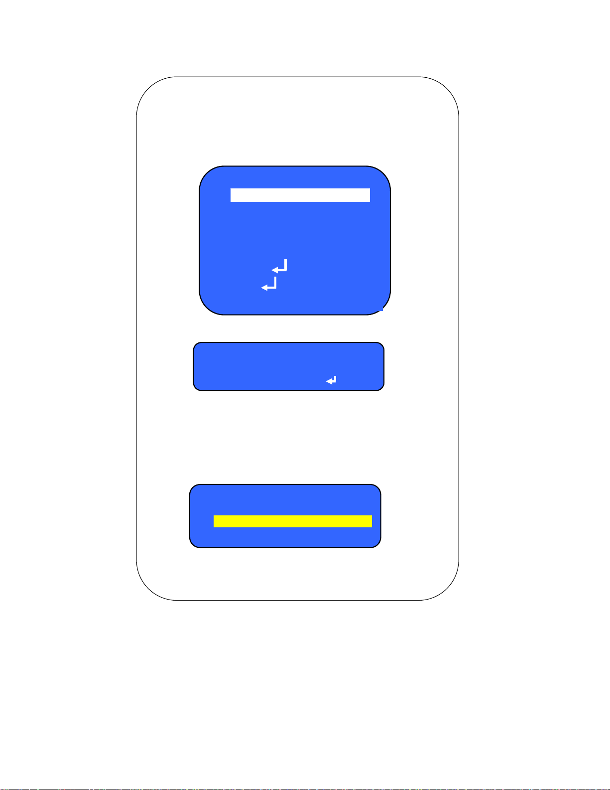
3. Move the Cursor by using the UP or DOWN button to choose the
SETUP
Choose the desired
Features to change
LENS DC
SHUTTER
B L C ON
A G C ON
WHITE BAL A T W
FUNCTION
ADJUST
Change the
values by
using
the LEFT or
RIGHT button
EXIT
4. Press the LEFT or RIGHT button to change the values.
5. To exit, choose the EXIT by using the DOWN button and press the SETUP
4
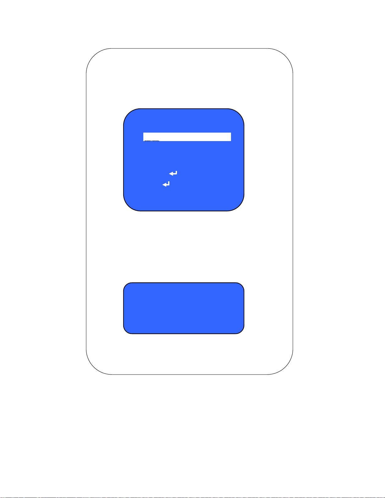
◈ LENS(Not Included)
Adjustment of brightness
1. Move the Indicator to LENS by pressing the UP or DOWN button in the SET UP
menu.
2. Select the desired LENS type by pressing the LEFT or RIGHT button.
SETUP
LENS DC
SHUTTER FIXED
B L C ON
A G C ON
WHITE BAL A T W
FUNCTION
ADJUST
EXIT
DC: DC Auto IRIS Lens
VIDEO: Video Auto IRIS Lens
MANUAL
Lens
VIDEO
DC
CAUTION
☞ If DC/VIDEO Auto IRIS Lens is selected, the SHUTTER SPEED should be "
FIXED".
If Manual IRIS Lens is selected, the SHUTTER SPEED should be "AUTO"
3. The brightness can be manually adjusted when DC Lens is selected.
Press the SET UP button and then adjust the brightness level by using the
the LEFT or Right button.
LENS DC
0 ~ 255
BRIGHTNESS
RETURN
4. Press the SET UP button again to return to the previous menu.
5
◈ SHUTTER SPEED
K
1. Move the Indicator to SHUTTER by pressing the UP or DOWN button in the
SET UP
menu.
2. Select the desired item by pressing the LEFT or RIGHT button.
SETUP
LENS DC
SHUTTER
B L C ON
A G C ON
WHITE BAL A T W
FUNCTION
ADJUST
EXIT
a). Fixed: Lens shutter speed will be fixed to 1/100 sec (default) when DC lens is
selected. The value can be changed with the LEFT or RIGHT button.
b). Manual: Shutter speed can be manually adjusted.
c). Auto: Shutter speed will be automatically controlled if the LENS is set to manual.
d). F L K: Select "FLK" when image is being flickered by flourescent lamp, radio
waves etc.
SHUTTER
Fixed
Manual
Auto
F L
3. Press the SET UP button again to return to the previous menu.
6
◈ BACKLIGHT(B L C)
1. Move the Indicator to BLC by pressing the UP or DOWN button in the
SET UP menu.
SETUP
LENS DC
SHUTTER
B L C ON
A G C ON
WHITE BAL A T W
FUNCTION
ADJUST
EXIT
2. Select the ON or OFF by pressing the LEFT or RIGHT button.
B L C
ON
OFF
3. The following menu will be displayed when the ON is selected.
B L C SET UP
B L C AREA
B L C RATIO 0 ~ 63
RETURN
7
4. Differential images between BLC is ON and BLC is OFF
BLC ON BLC OFF
5. Selection of BLC Area
- Select the BLC AREA in the BLC SETUP menu by using the UP/DOWN button.
- Press the SET UP button and the above screen will be displayed.
- Move the Yellow square with the UP/DOWN or the LEFT/RIGHT button to select
BLC area
and press the SET UP button.
- Press the SETUP button for one second to exit this mode after setting the BLC area
and then
the following menu will be appeared.
8

- Choose the ALL CLEAR to clear the BLC area in the above menu.
- Choose the ALL SET to set BLC area on the whole screen in the above
menu.
- Choose the RETURN to select BLC areas.
- Choose the EXIT to adjust BLC RATIO.
6. Adjustment of BLC RATIO
- Adjust BLC RATIO with the LEFT or RIGHT button.
- Choose the RETURN and press the SETUP button to go back to the SETUP
menu.
B L C SET UP
B L C AREA
B L C RATIO 0 ~ 63
RETURN
9

◈ A G C(Auto Gain Control)
AGC helps to increase the image brightness.
SETUP
LENS DC
SHUTTER
B L C ON
A G C ON
WHITE BAL A T W
FUNCTION
ADJUST
EXIT
1. Move the indicator to AGC by using the UP or DOWN button and
press the
2. When the ON is selected, press the SETUP button and then the AGC GAIN
CONTROL
menu will be displayed on the screen. Press the LEFT or RIGHT button to increase
or decrease AGC GAIN level.
A G C CONTROL
A G C GAIN 0 ~
EXIT
10

◈ WHITE BALANCE
- Move the Indicator to WHITE BAL by using the UP or DOWN button and press
the
RIGHT or LEFT button to select the ATW, AWB, FIXED and MANUAL.
SETUP
LENS DC
SHUTTER
B L C ON
A G C ON
WHITE BAL A T W
FUNCTION
ADJUST
EXIT
① ATW(Auto Tracking White Balance)
When color temperature is 1,800°K ~ 15,000°K, select this mode.
(Ex: A fluorescent lamp, or outdoors)
② AWB(Auto White Balance)
The white balance is automatically adjusted in a specific environment.
In order to obtain the best result, press the SETUP button while the camera
focuses on the white paper. If the environment including the light source
is changed, you have to adjust the white balance again.
③ FIXED(Auto White Balance Fixed)
Auto white balance is fixed and adjusted by 4 steps.
④ MANUAL:To fine adjust, select the manual mode.
- Move the Indicator to WHITE BAL by using the UP or DOWN button and press
the
RIGHT or LEFT button to select the MANUAL.
- Press the SETUP button and then the AWB MANUAL menu will be displayed.
11

WHITE BAL. ATW
AWB
FIXED
MANUAL
A W B MANUAL
RED 0 ~ 255
BLUE 0 ~ 255
RETURN
- Increase or decrease the value for RED(R-Gain) and BLUE(B-Gain) by
pressing the
LEFT or RIGHT button.
- After set up the desired value, move the Indicator to RETURN in the AWB
MANUAL
menu by pressing the DOWN button and press the SETUP button to return to
☞ CAUTION
Proper White Balance may not be obtained under the following
conditions.
In these case, select the AWB mode.
- When the scene contains mostly high color temperature object, such
as
blue sky or sunset.
- When the scene is dim.
- If the camera faces a fluorescent lamp directly or is in an area with
12

◈ FUNCTION
- Move the Indicator to FUNCTION in the SETUP menu by using the UP or DOWN
button and press the SETUP button to display the FUNCTION menu.
SETUP
LENS DC
SHUTTER
B L C ON
A G C ON
WHITE BAL A T W
FUNCTION
ADJUST
EXIT
FUNCTION
RETURN
CAMERA ID ON
MIRROR OFF
DAY & NIGHT AUTO
MOTION ON
PRIVACY ON
GAMMA 0.45
LANGUAGE
RESET
☞ CAUTION
- If the CAMERA TITLE is set to "OFF", the camera title will not be
displayed
on the monitor
13

1. CAMERA TITLE
P
D
N
N
p
Place the Cursor under the Character "C" by pressing the LEFT or
RIGHT
button and press the SETUP button to create the Camera title.
Press the RIGHT button to place the cursor to the first place of
ID SETU
CAMERA I
CURSOR
POSITIO
C
RETUR
Press the UP or DOWN button to select the required number or alphabet.
- Move the Cursor for next charater by pressing the RIGHT button.
( Character begins from number "0 ~ 9" and follows from" A ~ Z" )
After completing the CAMERA ID, place the Cursor under the ENTER symbol
and
press the SETUP button to choose the POSITION in the ID SETUP menu.
- Choose the POSITION in the ID SETUP menu with the UP or DOWN button
and
press the SETUP button.
- Move the CAMERA ID by using the UP or Down and LEFT or RIGHT button to
proper place to display on the screen and press the SETUP button to save.
Choose the RETURN in the ID SETUP menu by pressing the UP or DOWN
button
and
ress the SETUP button to return to the previous menu.
2. MIRROR
Press the RIGHT button to select the ON or OFF.
FUNCTION
RETURN
CAMERA ID ON
MIRROR OFF
DAY & NIGHT AUTO
MOTION ON
PRIVACY ON
GAMMA 0.45
LANGUAGE
RESET
14

2.MIRROR
☞ OFF : Deactivation
☞ ON: The image will be reversed as follows.
MIRROR ON MIRROR OFF
3. DAY & NIGHT
① Press the RIGHT button to set up the desired mode.
FUNCTION
RETURN
CAMERA ID ON
MIRROR ON
DAY & NIGHT AUTO
MOTION ON
PRIVACY ON
GAMMA 0.45
LANGUAGE
RESET
☞ COLOR: The camera will always display color images.
☞ B/W : The camera will always display B/W images.
☞ AUTO: The color images will switch to B/W images under the low light
conditions.
15

Press the UP or DOWN button to select desired mode.
Press the LEFT or RIGHT button to set up the desired value.
DAY NIGHT AUTO
DELAY 0 ~ 63
START LEVEL 0 ~ 255
END LEVEL 0 ~ 255
RETURN
4. MOTION
Whenever an object's motion is detected, the motion symbol will be
appeared
on the upper right corner of the screen.
Press the RIGHT button to set up the desired mode.
FUNCTION
RETURN
CAMERA ID ON
MIRROR ON
DAY & NIGHT AUTO
MOTION ON
PRIVACY ON
GAMMA 0.45
LANGUAGE
RESET
☞ CAUTION
- Press the RIGHT button to activate the MOTION or deactivate.
16

Press the SETUP button to display the MOTION menu on the screen.
ADJUSTMENT WHEN MOTION "ON"
MOTION
AREA
MOTION TH. 0 ~ 255
MOTION TRACE
RETURN
Choose the AREA in the MOTION menu and press the SETUP button to select
the motion area on the screen and then the Motion Area SETUP window will
be
displayed as follows.
How to set up Motion Areas
- Select the MOTION AREA in the MOTION menu by using the UP/DOWN button.
- Press the SET UP button and the above screen will be displayed.
- Move the Yellow square with the UP/DOWN or the LEFT/RIGHT button to select
MOTION
area and press the SET UP button.
- Press the SETUP button for one second to exit this mode after setting the MOTION
area
and then the following menu will be appeared.
17

MOTION AREA
ALL CLEAR
ALL SET
RETURN
- Choose the ALL CLEAR to clear the MOTION area in the above menu.
- Choose the ALL SET to set MOTION area on the whole screen in the above
menu.
- Choose the RETURN in the MOTION AREA menu to go back to the FUNCTION
5. PRIVACY
To mask the specific area where you want.
Choose the PRIVACY in the FUNCTION menu with the UP or DOWN button
and select the ON or OFF by pressing the LEFT or RIGHT button.
FUNCTION
RETURN
CAMERA ID ON
MIRROR ON
DAY & NIGHT AUTO
MOTION ON
PRIVACY ON
GAMMA 0.45
LANGUAGE
RESET
ON: PRIVACY mode Activated
OFF: Deactivated
18

5. PRIVACY
Press the SETUP button to display the PRIVACY menu when the ON is
selected.
Set the"PRIVACY" to desired mode using by the LEFT or RIGHT button.
PRIVACY AREA
AREA SEL AREA 0
LEFT 0 ~ 255
AREA STATE
RIGHT 0 ~ 255
TOP 0 ~ 255
BOTTOM 0 ~
COLOR 0 ~ 15
RETURN
☞ How to set up desired area value
1) Desired area could be selected upto 0 ~ 3 steps by pressing the RIGHT
botton.
2) Area state could be selected "ON" or "OFF" mode.
3) Area setup value could be changed by pressing the UP or DOWN & LEFT
or RIGHT utton.
4) Privacy area color could be changed up to 15 colors.
19

6. GAMMA
Gamma value could be adjusted by pressing the LEFT or RIGHT
button.
FUNCTION
RETURN
CAMERA ID ON
MIRROR ON
DAY & NIGHT AUTO
MOTION ON
PRIVACY ON
GAMMA 0.45
RESET
User's adjustment: 0.00 ~ 1.00
7. RESET
- Choose the RESET in the FUNCTION menu with the UP or DOWN button
and
press the SETUP button to select the YES or NO.
- If "YES" is selected, all the values will be changed to factroy default setting.
20

◈ ADJUST
5
Choose the ADJUST in the SETUP menu with the UP or DOWN button and press
the SETUP button to adjust contrast, sharpness, CB-gain and CR-gain.
SETUP
LENS DC
SHUTTER
B L C ON
A G C ON
WHITE BAL A T W
FUNCTION
ADJUST
EXIT
① Press the LEFT or RIGHT button to increase or decrease the desired
values.
ADJUST
COTRAST 0 ~ 25
SHARPNESS 0 ~ 255
CB - GAIN 0 ~ 255
CR - GAIN 0 ~ 255
RETURN
② Choose the RETURN in the ADJUST menu and press the SETUP button to
return
to the previous menu.
◈ EXIT
Choose the EXIT in the SETUP menu with the UP or DOWN button and
press
the SETUP button to exit.
21

u
TROUBLE SHOOTING
PROBLEM SOLUTION
●Check the power cable and line connection
Nothing appears on
the screen.
The image on the
Screen is dim.
between the camera and monitor.
● Check that you have properly connected the
video cables.
●Is the camera lens stained with dirt?
Clean the lens with a soft and clean cloth.
● Adjust the monitor as required.
● If the camera is exposed to very strong light,
change the camera position.
● Adjust the lens focus properly.
The image on the
Screen is dark.
The camera is not working
properly and the surface of
the camera is hot.
MOTION DETECTION
function is not active.
The color of the picture
is not matched.
The image on the
Screen flickers.
● Adjust the contrast feature of the monitor.
● If you have an intermediate device, set the 75Ω / Hi - z
properly.
● Check that you have properly connected the camera
to an appropriate power source.
● Have you set " MOTION DET" menu to off?
● Have you set " MD AREA" properly?
● Check that you have properly set the " WHITE BAL." men
● Is the camera facing direct sunlight or fluorescent
lighting?
Change the camera position.
22

Specifications
Image Sensor
Effective Pixels
Scanning System
Horizontal Resolution
Shutter Speed
Sync. System
S/N Ratio more than 50db (AGC off)
Minimum Illumination
Video Output
A G C
O S D
Motion Detection
Digital Noise Reduction
White Balance
Lens
Power Consumption
Power Supply
Operating Temperature
Dimension
1/3" Sony Super HAD CCD, 811H x 508V
768H x 494V
525 Lines, 2:1 Interlace
540 TV Lines
Auto, Manual ( 1/60 to 1/120,000 sec )
Internal
0.1 Lux @F1.2
Composite 1.0Vp-p @75 Ω
Off / On, 0 to 255
Camera ID & Menu
Off / On
Auto
ATW/ AWB, Manual (1,800˚K to 10,500˚K)
C & CS Mount Lens( Not included )
DC 12V 土 10%, 200mA Max.
AC 24V / DC 12V - (Non Polarity):
Not included
-'10ºC to 50ºC
55(W) x 50(H) x 120(D)mm ( without Lens )
23

* INSTALLATION * SETTINGS
Dimensions & Cable Connection
Settings can be made using the 5 buttons
located on the back panel on the camera.
FRONT BACK
SIDE
SIDE
1
1.Control(+)
Min. DC8V(Max. 0.5mA)
2 2.Control(-) N.C
3.Drive(-) VIDEO
3
4 4.Drive(+)
GROUND
OSD CONTROL
OSD
LENS
SHUTTER
BLC
AGC
WHITE BAL.
DC
AUTO
ON
ON
ATW
FUNCTION
ADJUST
EXITE
OSD - FUNCTION
RETURN
CAMERA ID ON
MIRROR OFF
DAY / NIGHT COLOR
MOTION OFF
PRIVACY OFF
GAMMA
0.45
LANGUAGE ENGLISH
RESET
24

Available accessories
LENS3508 1/3" CS mount, Vari-focal DC Auto IRIS lens, 3.5 to 8mm
TV3X0310D-NB 1/3" CS mount, Vari-focal DC Auto IRIS lens, 3.0 to 8.5mm
TV7X7513D-NB 1/3" CS mount, Vari-focal DC Auto IRIS lens, 7.5 to 50mm
HS13 Outdoor Camera Housing, 138(W) x 117(H) x 375(L)mm
HS13HB Outdoor Camera Housing, 138(W) x 117(H) x 375(L)mm w/
Heater & Blower, AC24V Power Supply(ADT241200: not included)
MBK010 Mounting Bracket for HS13 & HS13HB
MBK001 "L" type Mounting Bracket
ADT241200 AC to AC Power Supply AC24V 1.2A for HS13HB
CDR4170 Stand - alone 4CH DVR
CDR4770 MPEG-4 Stand - alone 4CH DVR
CDR0850 MPEG-4 Stand - alone 8CH DVR
CDR1610 Stand - alone 16CH DVR
Limited 2 Year Warranty
This warranty gives the original purchaser specific legal rights and you may also have
other rights, which may vary from state to state. If our products do not function because
of any defect in material or workmanship, we will repair it for free for 2 year on parts and
labor from the date of original purchase. This warranty does not cover modification,
abuse, incidental or consequential damages unless the state of owner's residence
Specially prohibits limitations on incidental or consequential damages.
How to obtain Factory Service
◈
Original purchaser must fill out the warranty card and mail it to the factory with the
model number, serial number and the date of purchase.
We will repair or replace, and return the system to the owner under this limited
◈
warranty.
Please pack the system carefully and securely using the original packing materials,
◈
and send it prepaid and insured to:13073 E. 166th St., Cerritos, CA 90703
Please include a check for US$15.00 to cover the cost of return postage and handling. If
◈
the system is returned within the warranty period, please I nclude a proof of purchase.
If the system is out of warranty, you will receive an estimate of the repair cost for
your approval before repair work will be started.

M E M O

Copyright © 2008 Clover Electronics U.S.A. All Rights Reserved.
 Loading...