

Page 1
Instruction Manual
1 Channel Mobile
Digital V i deo Recorder
Model MVR1020
Copyright © 2008 Clover Electronics U.S.A. All Rights Reserved.
Page 2

Contents
About This Unit ..................................................................................3
1. Unpacking ...........................................................................4
2. Features ………………………………………………………….. 5
3. Specifications ……………………………………………………..6
4. Installation ………………………………………………………..7
4-1. What to do before Installation ...................................................................7
4-2. How to Connect DC power to DVR unit ...................................................8
4-2-1. When Installing the DVR in a Vehicle ............................................8
4-2-2. When Using the DVR for Security Purpose ...................................9
4-3. How to Install the Mounting Bracket for DVR .......................................10
4-4. Installation Check Lists ...........................................................................11
4-5. Controls and Connectors on the DVR .....................................................12
4-5-1. Front ..............................................................................................12
4-5-2. Rear ...............................................................................................14
4-6. Remote Controller ...................................................................................16
5. How to Operate ............................................................................17
5-1. General Operation ....................................................................................17
5-2. Running for the First Time (Initializing) .................................................18
5-3. Live Mode ................................................................................................19
5-4. Setup ........................................................................................................20
5-4-1. Time/Date .......................................................................................21
5-4-2. FA./CF ............................................................................................22
5-4-3. Record ............................................................................................24
5-4-4. Motion / Alarm ...............................................................................26
5-5. Recording .................................................................................................28
5-5-1. Manual (Continuous) Recording ....................................................28
5-5-2. Alarm Recording ............................................................................28
5-5-3. Motion Recording ..........................................................................29
5-5-4. Alarm & Motion Recording ...........................................................29
5-6. Playback ...................................................................................................30
5-6-1. Playing from the first ......................................................................30
- 1 -
Page 3

5-6-2. Replaying by Time/Date Search .....................................................30
5-6-3. Search by Recording Lists ..............................................................31
6. Viewer ............................................................................................33
6-1. CF Card Viewer Installation ....................................................................33
6-2. CF Card Viewer .......................................................................................36
6-2-1. Playback .........................................................................................37
6-2-2. Backup ............................................................................................38
6-2-3. AVI File Converting .......................................................................39
6-2-4. Image Capture in JPEG File ...........................................................39
6-2-5. Print Button ....................................................................................40
6-2-6. Other Buttons .................................................................................41
6-3. Raw Data Backup ....................................................................................42
6-3-1. Other Buttons .................................................................................43
6-4. Backup Viewer ........................................................................................44
Appendix
1. Recording Time Table ..................................................................46
1-1. Recording Resolution 720 x 480 .............................................................46
1-2. Recording Resolution 360 x 480 .............................................................47
2. Limited 1year Warranty ..............................................................49
3. How to Obtain Factory Service ..................................................49
- 2 -
Page 4

About this manual
This is the instruction manual for 1 Channel Mobile DVR, Model MVR1020.
This manual describes how to install and operate the MVR1020 and provide
information regarding specifications and features of this product.
Please be sure to read this manual and follow the instructions when installing the
MVR1020.
If you have any questions or problems installing, please contact Clover Electronics at
877-327-5000.
- 3 -
Page 5
1. Unpacking
When unpacking the DVR Unit, please be cautious not to drop, throw or hit with force.
This may cause damage to the product that could lead to malfunctions.
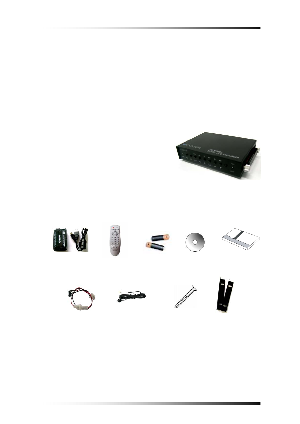
Before Installation please check if the following objects are included.
1 Channel Mobile DVR unit
Remote Controller & Batteries
Instruction Manual
CF Card Viewer CD
CF Card Reader (Optiona
Power Cable
Mounting Bracket 1 CH Mobile DVR
External IR Receiver (Optiona
l)
l)
CF Card Reader Remote Batteries CD-Rom Manual
(Optional) Controller
Power Cable Ext. IR Receiver Screws Mounting
(Optional) Brackets
Ú If any of the above items are missing please contact Clover Electronics.
- 4 -
Page 6

2. Features
Duplex (Record / Play-back)
Real Time Full Display mode
High Quality and Easy to install & control
Stand Alone Type (Non-PC, Non-OS)
On Screen Display
Built-in Time / Date Generator
Event lists of 990
Motion and Alarm detection recording
Quick Search: by Date & Time / Recording Lists
CF Card Overwrite
MJPEG Compression
Remote Control
- 5 -
Page 7
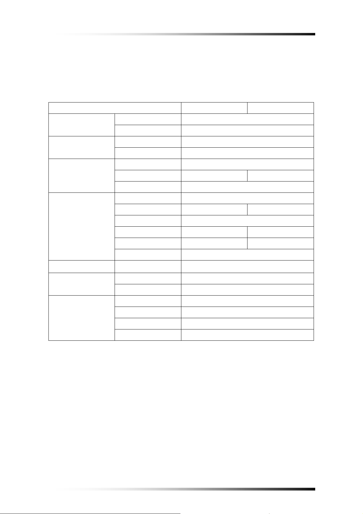
3. Specifications
System NTSC PAL
Video Signal
Audio
Display
Recording
Playback
Alarm Control
Input Composite 1Vp-p @ 75 Ohm, RCA(1CH)
Output Composite 1Vp-p @ 75 Ohm, RCA(1CH)
Input/Output 2 RCA(1CH Input, 1CH Output)
Recording Mode Mono PCM
Display Frame 30 FPS
Display Resolution 720×480 720×576
Screen Split Mode Full
Video Compression
M-JPEG codec core
Display Resolution 720×480/360×480 720×576/360×576
Recording Method Continuous, Event(Motion/Alarm)
Recording Speed 30 FPS 25 FPS
Image Full Size 3 ~ 25 KB 4 ~ 27 KB
Storage MLC, SLC type of CF Card supported
Search Search by Date/Time, Recording Lists
External Alarm Input
Alarm Input : Terminal Block
Alarm Output Alarm Output : Terminal Block
Remote Control IR Remote Control
Power 9V~ 40V / 1A (Locking Wafer Type)
Others
Dimension(mm) 123.5 × 88 × 29 mm
Weight 0.9Lbs
- 6 -
Page 8

4. Installation
4-1. What to do before Installation
Make sure all the required hardware is available.
- 1 Channel Mobile DVR unit (requires installing a CF Card)
- Camera (including power for camera unit)
- TV or Composite monitor
Connect a camera to the DVR unit and the DVR unit to the monitor (video output
device).
Connect DC power from vehicle to the DVR --- pay attention to the polarity
(Refer to section 4-2 for more information).
Confirm live video is displayed on the monitor before proceeding to the next step.
Select the Setup Menu and set the current date and time
Set values for required options such as motion detection, etc.
- 7 -
Page 9
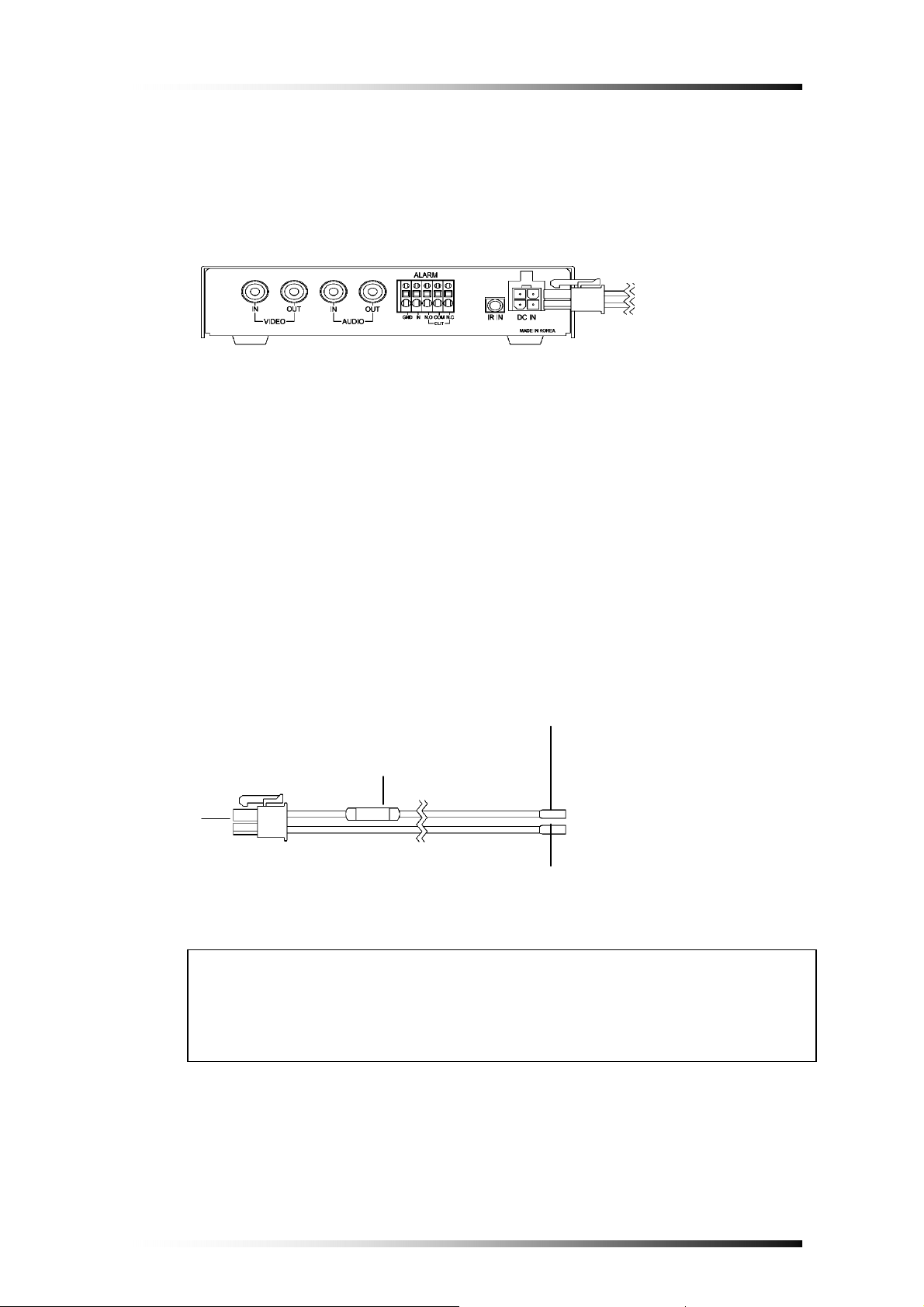
4-2. How to Connect DC power to DVR unit
(Rear View)
A
○
or ○B
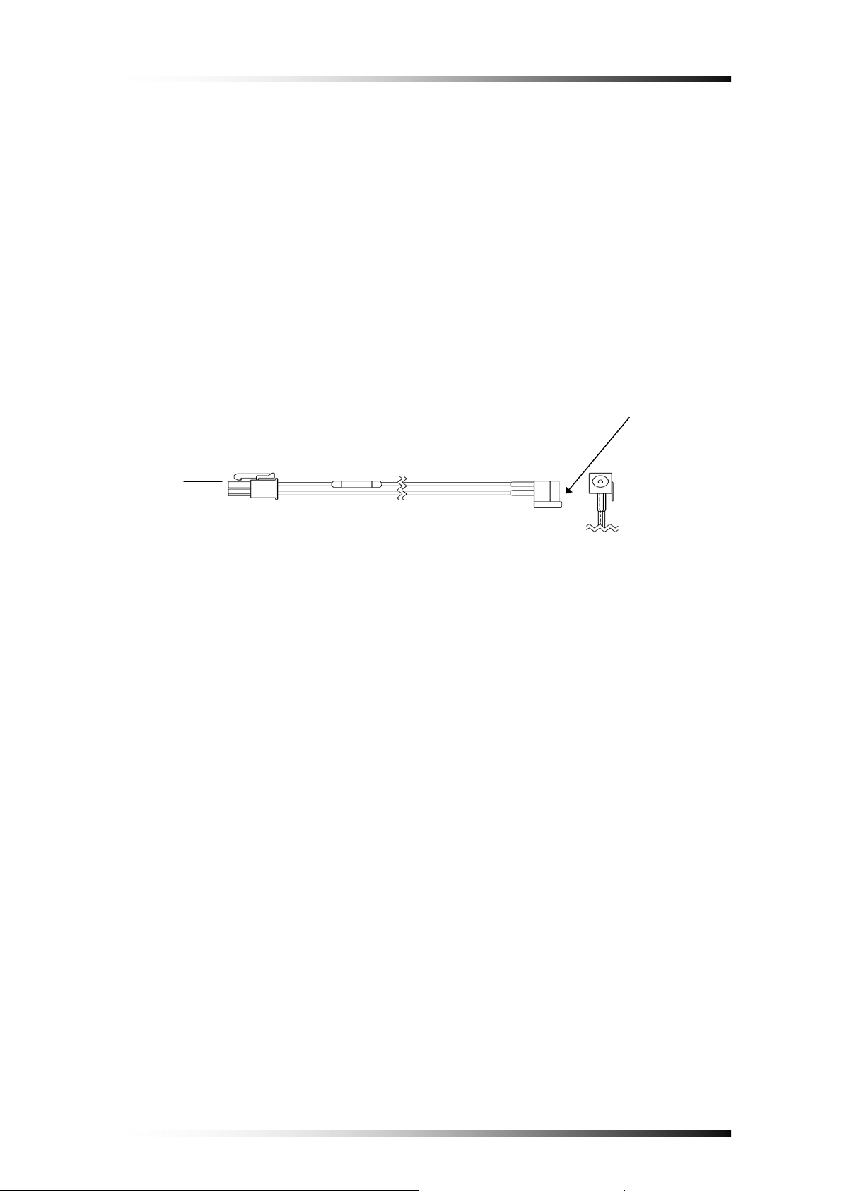
4-2-1. When Installing the DVR in a Vehicle
Cut out the DC jack on the provided DC power wires as shown in Fig.4-1, and
then connect wires as follows.
GROUND: Connect the BLACK colored wire to vehicle’s chassis (Do not
connect it to the gas tank or the airbag area).
DC 9V TO 40V (HOT): Connect the RED colored wire to the DC power line
that supplies DC 12V or DC 24V when ignition switch is in the “ON” position.
Red
Fuse (250V.3A)
A
○
Black
Fig.4-1 Power Cable
CAUTION
Connect the 4 pin connector with 2 wires in polarity to the power in jack on
4-2-1. When installing the DVR in a vehicle
the rear panel after connecting Ground and Hot (B+) as mentioned above.
- 8 -
Page 10
4-2-2. When Using the DVR for Security Purpose
Connect the 4pin connector with 2 wires in polarity to the power in jack on
▪
the rear panel of the DVR.
▪ Connect DC 12V or DC24V, 3A AC adapter (not supplied: Switching Power
Supply, center: +, outer: ground) to the DC jack on the provided DC power
wires shown in Fig.4-2.
B
○
Fig.4-2 Power Cable
DC Jack
- 9 -
Page 11
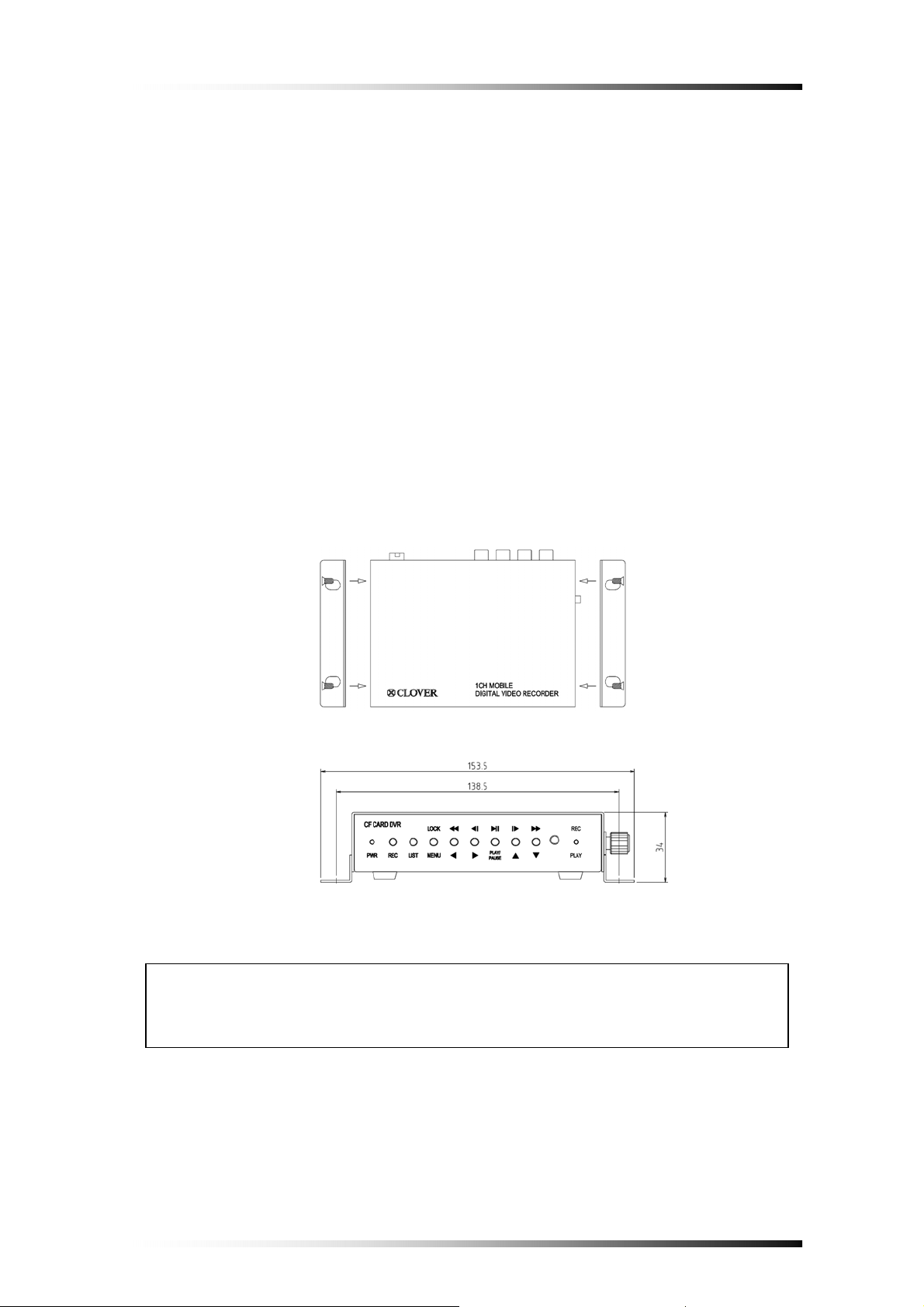
4-3. How to Install the Mounting Bracket for DVR
▪ Unscrew 2-locking screw knobs and 4 screws on both sides of the DVR.
▪ Attach the mounting bracket onto both sides of DVR and secure them with the
screws (See Fig. 4-3).
▪ If necessary, install the DVR with the mounting brackets to proper place in
your vehicle.
Fig.4-3 Installation of mounting bracket
CAUTION
Do not install the mounting bracket for DVR to the gas tank or airbag area.
- 10 -
Page 12

4-4. Installation Check Lists
Is the camera installed at the right position?
Is the camera cable connected to the input?
Is the audio cable connected to the input?
Is the system set on a stable location?
Is the system set on a stable location by mounting bracket?
Is the placement of the system clear from any elements such as water, excess
dust, direct sunlight, magnetic field, gas, oil and etc…
Is the system located away from temperatures beyond 32
Is the location of the DVR unit away from the reach out of children?
Are the batteries inserted correctly in the remote controller?
Is the video output cable connected to the correct jack?
Are all components (Camera, DVR) connected to the correct power supply?
ºF ~ 122ºF
CAUTION
Turn off the POWER when removing or inserting the Compact Flash
Card (CF Card) to the DVR.
- 11 -
Page 13
4-5. Controls and Connectors on the DVR
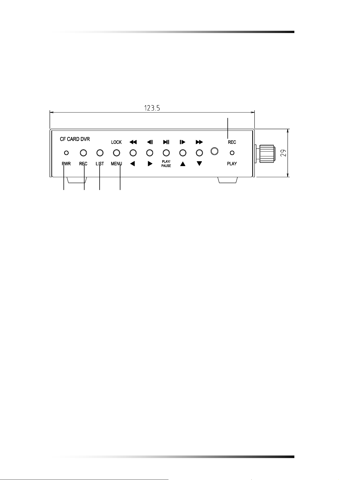
4-5-1. Front
②
①
⑤ ④ ③
Fig.4-4 Front View
1) PWR LED: Red light is lit when the power is ON
2) REC & PLAY LED: Green light will be blinking when the system is in the recording
or replaying mode, turn off during live mode.
3) REC Button: Press this button to start recording. To stop recording, press this button
again.
4) LIST: Recording lists (up to 990 lists) will display when this button is pressed. Press
this button again to exit.
5) MENU / LOCK / ESC / STOP
- MENU & ESC: Display on screen Menu or escape to screen.
- STOP: To stop replaying.
- LOCK: Press and hold this button for 3 seconds to lock the system.
When the system is locked, all the buttons and remote controller doesn’t
work. Press and hold this button for 3 seconds again to unlock. Refer to the
next screen showing the lock icon.
- 12 -
Page 14
Lock Icon
6) ARROW Buttons:
1
○2 ○3 ○4
○
Fig.4-5 Lock Icon
1
○
Used as Left and Rewind (x16) Key
2
○
Used as Right and previous Frame Key
3
○
Used as Up and next Frame Key
4
○
Used as Down and fast Forward (x16) Key
- 13 -
Page 15
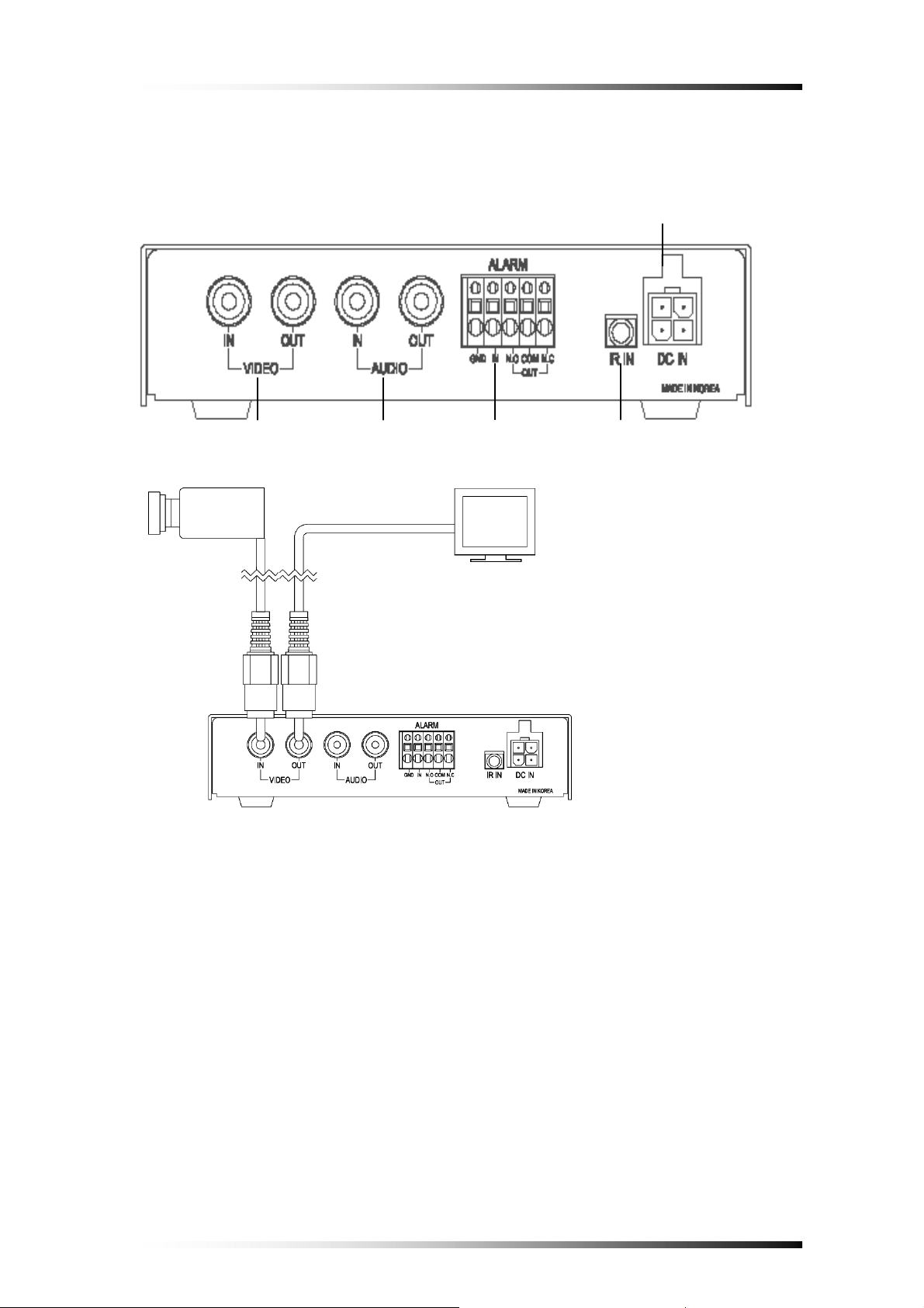
4-5-2. Rear
① ③ ④
②
⑤
1) Video IN/OUT
Connect a camera to the Video Input (RCA Connector) and a monitor to the Video
Output (RCA Connector) on the rear panel of the unit as shown in Fig.4-6.
2) Audio IN/OUT
If necessary, connect a microphone to the Audio Input (RCA Connector) and a
speaker to the Audio Output (RCA Connector) on the rear panel of the unit.
Fig.4-6 Rear View
- 14 -
Page 16

3) Alarm IN/OUT
Connect a Normally Open (N.O.) sensor to the Alarm Input and a Normally Open
(N.O.) sensor or Normally Close (N.C.) sensor to the Alarm Output depending on
your application.
4) IR Remote Control Extender (Optional)
Plug the IR remote control extender to the jack in order to extend the remote control
distance.
5) 4-pin Power Connector
Refer to section 4-2.
- 15 -
Page 17

4-6. Remote Controller
○1 The functions of keys listed
below are not available on this
2
○
3
○
Fig.4-7 Remote Controller
Refer to section 4-5-1 on how to operate.
4
○
model.
① USB & CDRW key
2
○
Numeric keys
③ Far & Near key
4
○
PT/ZF key
- 16 -
Page 18

5. HOW TO OPERATE
5-1. General Operation
You can operate the functions of the system by using the buttons located on the
front panel of the DVR unit, as well as the remote controller.
The system status is indicated by either the LED lights or the monitor.
- 17 -
Page 19

5-2. Running for the First Time (Initializing)
When you turn on the power for the first time, the screen will be shown as below.
1
○
Fig.5-1Initializing
① : Displays CF Card capacity available for recording.
② : Displays firmware version.
③ : Displays the date and time on the top of screen.
②
③
Note
If a CF Card is not in the DVR, the error message “MEM. ERROR” will
display on the screen as shown Fig. 5-2.
Fig.5-2 Error Message
- 18 -
Page 20

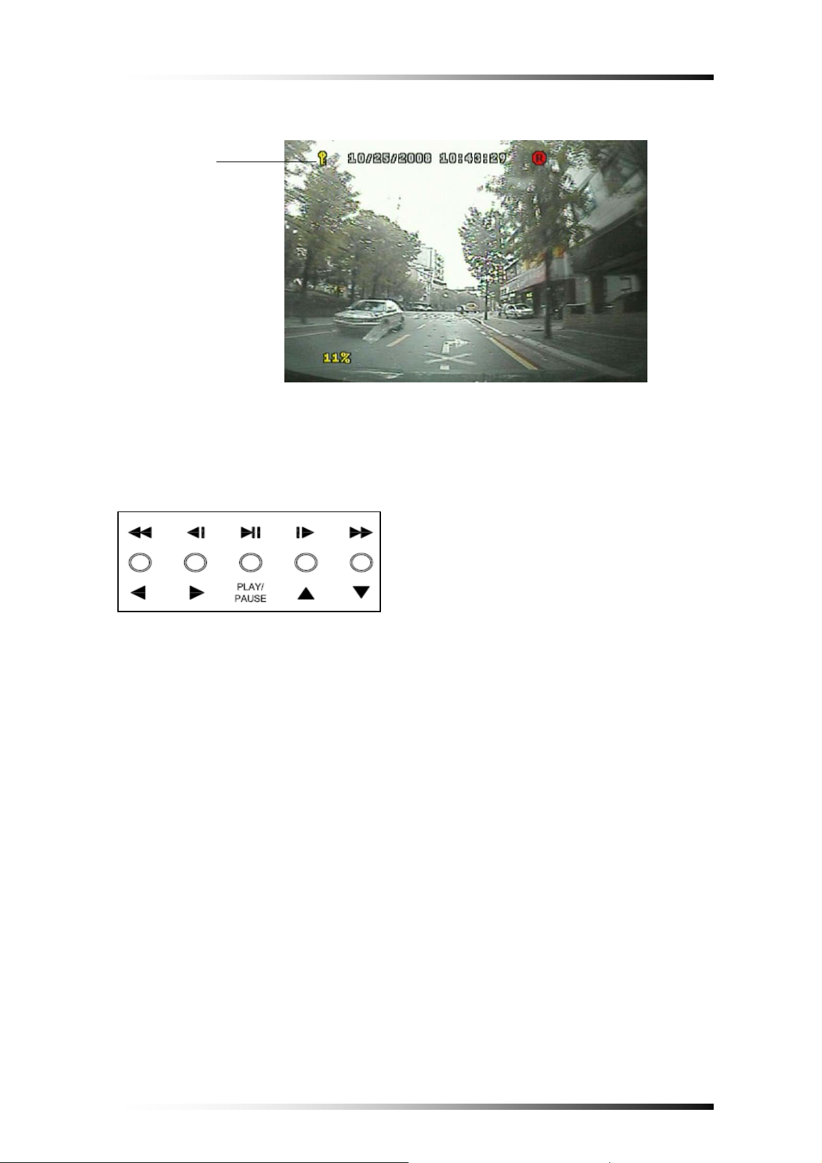
5-3. Live Mode
①
① Current time/date
② CF Card use
③ Recording Icon
④ Motion & Alarm Icon
② ③
④
Fig.5-3Live Mode
- 19 -
Page 21

5-4. Setup
- Press the MENU button on the front panel or the remote controller to setup the
menus, the screen shown in Fig.5-4 will be displayed.
- Press the MENU button again to return to the previous menu.
① Capacity of CF Card ② Version of System
③ Icons
Fig.5-4 Menu Icons
- Choose one of menus by using the ◀▶ button and press the ▼ or ▲ button to
setup the menus.
- 20 -
Page 22

5-4-1. Time/Date
- Choose the TIME menu by using the ◀▶ button.
- Press the ▼ or ▲ button, the TIME/DATE menu shown in Fig. 5-5 will display.
Fig.5-5 T ime/Date Menu
- Select the values (year/month/date/hour/minute) by using the ◀▶ button,
change the values with the ▼ or ▲ button. Selected values (or items) will be
highlighted in yellow.
Display
- Select the DISPLAY in the Time/Date menu by using the ◀▶ button and
select YES or NO with the ▼ or ▲ button.
- If “YES” is selected, time and date will be displayed on the top of the screen,
but if “NO” is selected, it won’t be displayed.
Date Format
There are three kinds of formats to display the time and date.
▪ MM / DD / YYYY: for U.S.A.
▪ YYYY / MM / DD: for Asian countries.
▪ DD / MM / YYYY: for European countries.
- Select the DATE FORMAT in the Time/Date menu by using the ◀▶ button
and select the date format with the ▼ or ▲ button.
- 21 -
Page 23

5-4-2. FA./CF
- Choose the FA./CF menu by using the ◀▶ button.
- Press the ▼ or ▲ button, the FA./CF menu shown in Fig. 5-6 will display.
Fig.5-6 FA./CF Menu
Factory Set
- Select the FACTORY SET in the FA./CF menu by using the ◀▶ button and
select YES or NO with the ▼ or ▲ button. Selected item will be highlighted in
yellow.
- Select “YES” and then press the PLAY button on the front panel or the remote
controller for factory default settings.
CF Format
- Select the CF FORMAT in the FA./CF menu by using the ◀▶ button and
select YES or NO with the ▼ or ▲ button. Selected item will be highlighted in
yellow.
- Select “YES” and then press the PLAY button on the front panel or the remote
controller for formatting the Compact Flash (CF) Memory Card.
Note
Formatting on the new CF Card or the used one should be performed in
the live mode before recording.
- 22 -
Page 24

REC List Clear
- Select the REC LIST CLEAR in the FA./CF menu by using the ◀▶ button
and select YES or NO with the ▼ or ▲ button. Selected item will be
highlighted in yellow.
- Select “YES” and then press the PLAY button on the front panel or the remote
controller for deleting the recording lists.
- 23 -
Page 25

5-4-3. Record
- Choose the RECORD menu by using the ◀▶ button.
- Press the ▼ or ▲ button, the RECORD menu shown in Fig. 5-7 will display.
Fig.5-7 Record Menu
Fig.5-7 Record Menu
Quality
- Select the QUALITY in the RECORD menu by using the ◀▶ button and
select one of recording qualities among High+, High, Middle, Low and Lowwith the ▼ or ▲ button. Selected item will be highlighted in yellow.
The higher the level selected (e.g. High+), the better display quality is but the
larger the data becomes.
Speed
- Select the SPEED in the RECORD menu by using the ◀▶ button and select
one of recording speed among 30FPS, 15, 7.5, 5, 2.5, 1.5, 1 and 0.5 with the ▼
or ▲ button. Selected item will be highlighted in yellow.
The more the frames selected (e.g. 30FPS), the better real time display is but the
larger the data becomes.
Audio
- Select the AUDIO in the RECORD menu by using the ◀▶ button and select
YES or NO with the ▼ or ▲ button. Selected item will be highlighted in yellow.
- 24 -
Page 26

Event REC Time
- Select the EVENT REC TIME (Event Recording Time by Alarm or Motion
Detection) in the RECORD menu by using the ◀▶ button and select an event
recording time (1 to 99 seconds) with the ▼ or ▲ button. Selected item will be
highlighted in yellow.
Resolution
- Select the RESOLUTION in the RECORD menu by using the ◀▶ button and
select 720 x 480 or 360 x 480 with the ▼ or ▲ button. Selected item will be
highlighted in yellow.
CF ID
- Select the CF ID in the RECORD menu by using the ◀▶ button and setup an
ID for CF Cards by using the ▼ or ▲ button. Selected item will be highlighted
in yellow.
CF Card ID. No.
Fig.5-8 CF Card ID in the playback mode
- 25 -
Page 27

5-4-4. Motion/Alarm
- Choose the RECORD menu by using the ◀▶ button.
- Press the ▼ or ▲ button, the MOTION/ALARM menu shown in Fig. 5-9 will
be displayed.
Fig.5-9 Motion/Alarm Menu
Sensitivity
- Select the SENSITIVITY in the MOTION/ALARM menu by using the ◀▶
button and select one of sensitivities among Very high, High, Middle, Low and
Very low with the ▼ or ▲ button. Selected item will be highlighted in yellow.
Area
- Select the area in the MOTION/ALARM menu by using the ◀▶ button and
press the ▼ or ▲ button to open the window for motion detection area setup.
- When the window for motion detection area setup as shown in Fig.5-10 is
displayed on the screen, press the LIST button on the front panel or the remote
controller for choosing all the motion detection areas. The symbol, “O” will be
displayed, and it represents motion detection areas. The symbol, “X” represents
cleared motion detection areas.
Press the LIST button again to clear all the areas.
- Press the ◀▶ button and ▼ or ▲ button to setup motion detection area on the
specific region.
- Press the MENU button to return to the previous menu.
- 26 -
Page 28

Fig.5-10 Motion Detection Area Setup
Alarm
- Select the Alarm in the MOTION/ALARM menu by using the ◀▶ button and
select YES or NO with the ▼ or ▲ button. Selected item will be highlighted in
yellow.
- 27 -
Page 29

5-5. Recording
There are four kinds of recording available in this system.
- Manual recording: Continuous recording
- Alarm recording: Recording by alarm sensors
- Motion recording: Recording by motion detection
- Alarm & Motion recording: Recording by alarm sensors and motion detection
simultaneously.
5-5-1. Manual (Continuous) Recording
The user can manually start recording the video footage by pressing the REC
(Recording) button on the front panel or the remote controller.
The manual recording will start recording only if the alarm and motion detection are
not set. The recoding icon will be displayed on the top of the screen as shown in
Fig.5-11.
Fig.5-11 Manual Recording Icon
5-5-2. Alarm Recording
The system will automatically start recording only when an alarm is activated.
- Select “YES” on the ALARM in the MOTION/ALARM menu (See section 5-4-4
for more details).
- Press REC button on the front panel or the remote controller.
- 28 -
Page 30

5-5-3. Motion Recording
The system will automatically start recording only when motions of object are
detected.
- Setup the AREA (motion area) in the MOTION/ALARM menu (See section 5-4-4
for more details).
- Press REC button on the front panel or the remote controller.
5-5-4. Alarm & Motion Recording
Refer to section 5-5-2 and 5-5-3.
- Fig.5-12 shows that any of alarm or motion detection is not activated and the icons
in white on the bottom of screen are displayed.
- Fig.5-13 shows that alarm and motion are activated and the icons in red on the
bottom of screen are displayed.
Fig.5-12 Manual Recording Icon
Fig.5-13 Alarm/Motion Recording Icon
- 29 -
Page 31

5-6. Playback
The screen shown in Fig.5-14 will appear if the PLAY button on either the front
panel or the remote controller is pressed in the live mode.
Fig.5-14 Screen in Playback Menu
5-6-1. Replaying from the first
- In order to replay from the first recording time, select the REPLAYING FROM
THE FIRST in the PLAY menu as shown in Fig.5-14 by using the ◀▶ button.
- Press the PLAY button to playback (See Fig.5-15).
- Press the ◀ button or the MENU button to exit.
5-6-2. Replaying by Time/Date Search
- In order to replay by time/date search, select the REPLAY ING by Time/Date
Search in the PLAY menu as shown in Fig.5-14 by using the ◀▶ button.
- To set the Playback Start Time, select year, month, day, hour, minute and second
on the TIME (e.g.: [2008/11/10 10:57:19]) with the ◀▶ button and press the ▼
or ▲ button to select the Time/Date. Selected item will be highlighted in yellow.
- Press the PLAY button to playback (See Fig.5-15).
- To exit, press the ◀ button twice or the MENU button.
- 30 -
Page 32

① ② ③
④ ⑤
Fig.5-15 Replaying Screen
① CF Card ID
② Time & Date
③ Playback Status: Playback or Pause
④ CF Card used rate
5-6-3. Search by Recording Lists
- Press the LIST button on the front panel or the remote controller, up to 990
recording lists will be displayed as shown in Fig. 5-16.
- Select one of the lists by using the ◀▶ button, the selected list will be
highlighted in yellow.
- Press the PLAY button to playback. If the CF Card contains the corresponding
recording list, the system will start replaying. But if it doesn’t, the message of
“Out of Range” in red will be displayed on the screen, and then the system will
automatically start replaying from the first recording time.
⑤ Playing Speed: Up to 16 times
- Switch the page for recording lists by pressing the ▼ or ▲ button.
- 31 -
Page 33

Fig.5-16 Recording Lists
The abbreviations on the end of the lists represent as below,
respectively.
A: Alarm Recording
P: Power on
M: Motion Recording
R: Manual Recording
- 32 -
Page 34

6. VIEWER
6-1. CF Card Viewer Installation
Install the program in your PC by using the supplied CD as follows.
- Start the Operating System (Windows XP/VISTA).
- Insert the program CD into CD-ROM drive.
- Open My Computer, and then select CD-ROM drive.
- Double click Setup.Exe. The software installation will begin.
- Click “NEXT” button in Fig.6-1.
Fig.6-1 Installation of CFCard Viewer
- 33 -
Page 35

Fig.6-2 Installation of CFCard Viewer
- Click “Install” button in Fig.6-2 for installation.
Fig.6-3 Installation of CFCard Viewer
- Click “Abort” button in Fig.6-2 to abort installation.
- Skip to next step for installation.
- 34 -
Page 36

After installing, the CFCardViewer shown in Fig.6-4 will be displayed on the screen.
Fig.6-4 Installation of CFCard Viewer
Fig.6-5 Installation of CFCard Viewer Completed
- 35 -
Page 37

The Icon of CFCard Viewer will be created on the desktop as shown in Fig.6-6.
Fig.6-6 Icon for CFCard Viewer
6-2. CFCard Viewer
By CFCard Viewer you can view the recorded data, save it to a PC and convert it to
AVI file format.
- Insert the CFCard that contains the record data to the provided USB 2.0 Card
Reader.
- Connect the provided USB cable to the USB 2.0 Card Reader and PC.
- Double click the Icon of CFCard Viewer on the desktop, and then the screen
shown in Fig.6-7 will be displayed.
Fig.6-7 CFCard Viewer
- 36 -
Page 38

- Click the USB device (CFCard) on the upper right hand corner of the screen to
select (See Fig.6-8).
- To exit, click on the upper right hand corner of the screen, press ESC or
ALT+F4 button on your key board.
Fig.6-8 Selection of USB device (CFCard)
6-2-1. Playback
- After selecting the USB device (CF Card), click the DVR as shown in Fig.6-9.
- Select the Date (year/month/day) on the calendar by clicking the highlighted
character in blue that contains the recorded data.
- Click the
button to playback.
Fig.6-9 Selection of DVR Button
Control Buttons to Playback
: Click Play button to start playback.
: Click Reverse Play button to begin reverse playback.
: Click Pause button to pause.
: Click these buttons to view the previous frame or the next frame in still
image.
Playing Speed Control: Adjust play speed up to 5 times by clicking the slider and
dragging it or clicking the bar. Move the slider to the center of the bar for normal
playing speed (See Fig.6-10).
- 37 -
Page 39

Fig.6-10 Playing Speed Control
Adjust Audio V olume: Click the VOLUME button in Fig.6-11, and then adjust audio
volume by clicking the slider and dragging it or clicking the bar. It is available at the
normal playing speed.
Click the VOLUME button again to make it “Mute”.
Fig.6-11 Audio Volume
6-2-2. Backup
- Click the Save button shown in Fig.6-12 while the system is in the playback mode
(Refer to section 6-2-1).
- The current images on the screen will be saved in the CFCard_DVR_BK folder
(C:\CFCard_DVR_BK)
Fig.6-12 Selection of DVR/Save Button
- 38 -
Page 40

6-2-3. AVI File Converting
- Click the AVI and Save button shown in Fig.6-13 while the system is in the
playback mode (Refer to section 6-2-1).
- The AVI file will be saved in the CFCard_DVR_BK folder
(C:\CFCard_DVR_BK).
- To play, double-click one of the AVI files (Open Windows Explorer – click My
computer – click “C” dive – click CFCard_DVR_BK folder.
Fig.6-13 Selection of AVI/Save Button
6-2-4. Image Capture in JPEG File
- Righ-click on the screen of the CF Card Viewer, and then the pop-up screen will
be displayed as shown in Fig.6-14.
- Click “Cam 01 Image” on the pop-up screen to save the Ch 1 image in the
CFCard_DVR_BK folder (C:\CFCard_DVR_BK) in JPEG file format.
- To view, double-click one of the JPEG files (Open Windows Explorer – click My
computer – click “C” dive – click CFCard_DVR_BK folder.
- 39 -
Page 41

Fig.6-14 Pop-up Screen
6-2-5. Print Button
- Click the Print button shown in Fig.6-15 on the CF Card Viewer, and then the
print window (See Fig.6-16) that contains current printing time, record time and
CF Card ID will display.
- Press the Print button in Fig.6-16 to print out the current images.
Fig.6-15 Print Button
- 40 -
Page 42

Fig.6-16 Print Window
6-2-6. Other Buttons
- To display a full screen, click “1 x 1” button or double-click on one of split
screens.
- To display split screens, click “2 x 2” button or double-click on a full screen.
- Select NTSC or PAL by clicking depends on your country’s broadcasting system
(NTSC in U.S.A.).
- 41 -
Page 43

6-3. Raw Data Backup
Raw Data Backup is to save all the recorded data or partial data that stored in CF
Card in your PC.
- Click the USB device (CFCard) on the upper right hand corner of the CFCard
Viewer to select (See Section 6-2 for more details).
- Click the Raw Data Backup button shown in Fig.6-17 if you wish to save all the
recorded data in your PC, and then the saving progressive bar along with
percentage will appear as shown in Fig.6-18.
- If you wish to save a part of the whole recorded data, select the starting time by
clicking on the yellow bar that represents the whole recorded data as shown in
Fig.6-19 and set the ending time by right-clicking on it (See Fig.6-20), and then
click the Raw Data Backup button.
- The recorded data will be saved in the CFCard_DVR_BK folder
(C:\CFCard_DVR_BK).
- To play,
▪ Click the “Raw Data Open” in Fig.6-17, and then the Raw Data Backup Files
will be displayed (See Fig.6-21).
▪ Click one of the files, and then click “Open” button in Fig.6-21.
▪ Click the
button to playback.
Fig.6-17 Raw Data Backup/Open button
Fig.6-18 Saving prog ressive bar
- 42 -
Page 44

Fig.6-19 Whole Record Data
Fig.6-20 Set the Starting/Ending time
6-3-1. Other Buttons
The above buttons are not available on this version.
Fig.6-21 Raw Backup Files
- 43 -
Page 45

6-4. Backup Viewer
- Double click the Icon of Backup Viewer on the desktop, and then the screen
shown in Fig.6-22 will be displayed.
Fig.6-22 Backup Viewer
To playback, click one of the backup files and drag & drop to one of split
screens as shown in Fig.6-23.
- 44 -
Page 46

Fig.6-23 Click one file and Drag & Drop to CH 1
- 45 -
Page 47

APPENDIX
1. Recording Time Table
1.1 Recording Resolution: 720 x 480, Recording Time: Minutes
CF Card 1 GB
Frame/Sec. High+ High Middle Low Low-
30 9 12 15 17 21
15 18 23 28 34 41
7.5 35 44 55 66 79
5 51 66 82 99 118
2.5 99 126 158 190 226
1.5 171 219 274 329 391
1 267 341 427 512 609
0.5 507 648 811 973 1157
CF Card 4 GB
Frame/Sec. High+ High Middle Low Low-
30 39 50 63 75 89
15 75 95 119 143 170
7.5 145 186 233 279 332
5 216 277 346 415 494
2.5 415 531 664 797 948
1.5 719 921 1151 1381 1643
1 1120 1433 1792 2150 2559
0.5 2128 2723 3404 4085 4861
CF Card 8 GB
Frame/Sec. High+ High Middle Low Low-
30 71 100 124 146 172
15 142 182 227 273 324
7.5 277 354 443 531 632
5 412 527 659 790 941
2.5 790 1012 1265 1518 1806
1.5 1370 1753 2192 2630 3130
1 2133 2730 3413 4095 4874
0.5 4053 5188 6484 7781 9260
- 46 -
Page 48

CF Card 16 GB
Frame/Sec. High+ High Middle Low Low-
30 141 199 246 290 341
15 283 363 452 545 645
7.5 554 708 886 1062 1264
5 824 1054 1318 1580 1882
2.5 1580 2024 2552 3022 3612
1.5 2740 3502 4312 5260 6250
1 4265 5460 6825 8150 9904
0.5 8120 10250 12854 15640 18520
1-2. Recording Resolution: 360 × 480, Recording Time: Minutes
CF Card 1 GB
Frame/Sec. High+ High Middle Low Low-
30 16 20 25 30 35
15 30 39 49 59 68
7.5 59 76 86 115 133
5 88 113 142 171 198
2.5 172 220 277 333 386
1.5 294 376 473 568 659
1 457 591 745 894 1037
0.5 891 1153 1452 1743 2021
CF Card 4 GB
Frame/Sec. High+ High Middle Low Low-
30 67 86 108 130 151
15 128 124 206 247 287
7.5 249 319 402 482 559
5 371 474 598 717 832
2.5 723 925 1165 1398 1622
1.5 1233 1578 1988 2386 2768
1 1920 2482 3128 3753 4353
0.5 3743 4841 6099 7319 8490
- 47 -
Page 49

CF Card 8 GB
Frame/Sec. High+ High Middle Low Low-
30 125 160 201 242 280
15 243 312 392 471 546
7.5 475 607 765 918 1065
5 706 903 1138 1366 1584
2.5 1376 1762 2220 2663 3090
1.5 2348 3006 3788 4545 5272
1 3657 4728 5958 7149 8293
0.5 7130 9220 11618 13941 16172
CF Card 16 GB
Frame/Sec. High+ High Middle Low Low-
30 250 320 405 485 560
15 485 620 762 910 1085
7.5 955 1214 1512 1832 2124
5 1412 1806 2275 2655 3862
2.5 2744 3525 4445 5223 6180
1.5 4690 6012 7492 9092 10254
1 7210 9420 11862 14526 16543
0.5 14260 18446 23264 27864 32540
Note
- Recording Times differ widely depending on environment, camera quality, settings
and so on.
- We recommend you use CF Cards manufactured by SansDisk, Sony and Laxar.
Speed should be 300X or higher, if the speed is lower than 300X, some errors may
occur in the recording process.
- 48 -
Page 50

2. Limited 1 Year Warranty
This warranty gives the original purchaser specific legal rights and you may also have
other rights, which may vary from state to state. If our products do not function because
of any defect in material or workmanship, we will repair it for free for 1 year on parts
and labor from the date of original purchase. This warranty does not cover modification,
abuse, incidental or consequential damages unless the state of owner’s residence
specially prohibits limitations on incidental or consequential damages.
3. How to obtain Factory Service
* Original purchaser must fill out the warranty card and mail it to the factory with the
model number, serial number and the date of purchase.
* We will repair or replace, and return the system to the owner under this limited
warranty.
* Please pack the system carefully and securely using the original packing materials,
and send it prepaid and insured to: 13073 E. 166th St, Cerritos, CA 90703.
* Please include a check for $15.00 to cover the cost of return postage and handling. If
the system is returned within the warranty period, please include a proof of purchase.
If the system is out of warranty, you will receive an estimate of the repair cost for
your approval before repair work will be started.
- 49 -
 Loading...