

Clover Electronics HDC553 User Manual

INSTRUCTION
MANUAL
DAY/NIGHT LONG RANGE
VARI-FOCAL COLOR CAMERA
MODEL HDC553
Copyright © 2009 Clover Electronics U.S.A. All Rights Reserved.

PRECAUTIONS
• To avoid electrical shock, do not open the case of this product.
• Do not stamp fingerprints on the window for lens.
• Operate this product using only the supplied AC Power supply.
• Do not overload electrical outlets or extension cords; this can result in fire or electric
shock.
• Keep this product away from strong magnetic fields.
• Do not expose this product in direct sunlight or strong reflected rays.
• Refer servicing to qualified personnel only.
• Do not change or modify this product, the warranty will be voided.
FEATURES
• Weatherproof (IP67)
• 1/3” Sony Super HAD CCD
• High Resolution 550 TV Lines (Color), 600 TV Lines (B/W)
• True Day/Night (Built-in ICR: IR Cut Filter Removal)
• On Screen Display (OSD)
• 3D DNR (Digital Noise Reduction) with 3D filter
• D-WDR (Digital Wide Dynamic Range)
• Built-in Heaters
• Total 112 Infrared LEDs with a CDS sensor
• Up to 260’ IR range (depends on scene reflection)
• DC Auto Iris Vari-focal Lens (5-50mm)
• Attached Universal Mounting Bracket and 100’ cable
• Dual Voltage(AC 24V/DC 12V)
INSTALLATION
1. Get rid of the sun-visor① by turning the screw counter-clockwise on it.
2. Attach the mounting bracket base② to the wall or ceiling, wherever you want to
install the camera. Locate a wall stud or ceiling joist and secure the bracket base②
using the supplied screws③. Attach the mounting bracket④ to the mounting base②
and secure them using the supplied screws⑤.
3. Lock the mounting bracket with the locking ring⑥.
4. Turn the pivot locking screw⑦ with the provided hex-head wrench counter-
clockwise to set the desired angle of camera toward objects and turn it clockwise to
secure. It can be used for wall-mount or ceiling-mount application depending on
setting this pivot locking screw.
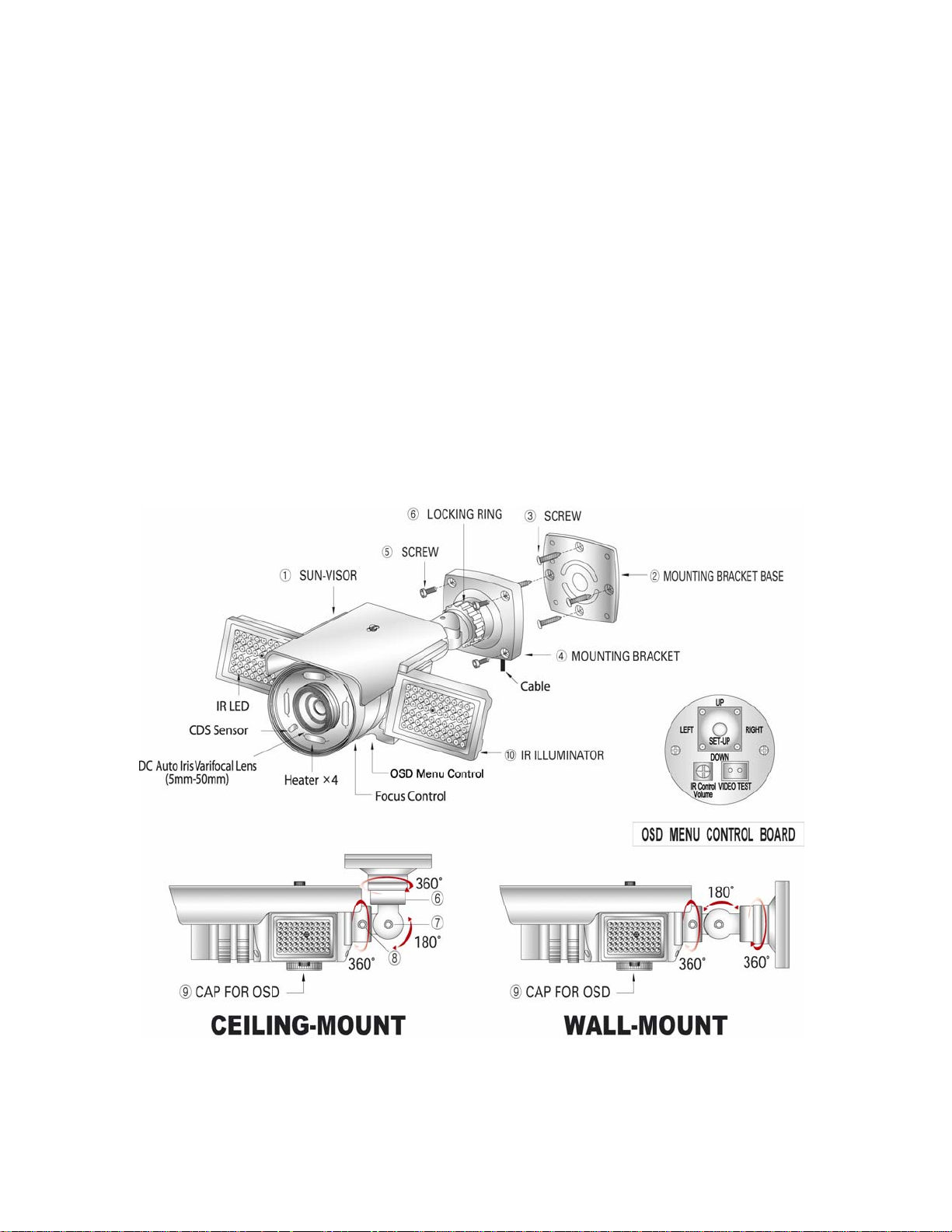
5. Loosen the locking screw⑧ with the provided hex-head wrench and turn the camera
clockwise or counter-clockwise to upright images on the screen and turn it clockwise
to secure.
6. If necessary, change the settings to get the best images depending on your application
by using the button on the bottom of the camera.
- Get rid of the cap⑨ for the OSD button by turning counter-clockwise and then
change the settings (refer to the included instruction manual for OSD).
- Turn the cap clockwise to secure after changing the settings.
7. Unfold the two IR illuminators⑩ to enlarge the IR range at night.
8. Put the sun-visor back to the camera and fix it with the screw.
9. Connect the one end of 100’ BNC cable (supplied) to the BNC (F) of 5’ cable
attached to the camera and the other end (BNC) of cable to the video devices such as
DVR, monitor/TV. Plug the provided AC power supply to the DC jack (red) on the
end of 100’ cable.
 Loading...