

Page 1

INSTRUCTION
MANUAL
3D-DNR
TRUE DAY/NIGHT IR CAMERA
MODEL HDC150
Copyright © 2009 Clover Electronics U.S.A. All Rights Reserved.
Page 2

PRECAUTIONS
• To avoid electrical shock, do not open the case of this product.
• Operate this product using only the supplied AC Power supply.
• Do not overload electrical outlets or extension cords; this can result in fire or electric
shock.
• Keep this product away from strong magnetic fields.
• Do not expose this product in direct sunlight or strong reflected rays.
• Refer servicing to qualified personnel only.
• Do not change or modify this product, the warranty will be voided.
FEATURES
• Weatherproof (IP67)
• 1/3” Sony Super HAD CCD
• High Resolution 550 TV Lines (Color), 600 TV Lines (B/W)
• Rugged Steel Construction
• On Screen Display (OSD)
• True Day/Night (Built-in ICR: IR Cut Filter Removal)
• 3D DNR (Digital Noise Reduction) with 3D filter
• D-WDR (Digital Wide Dynamic Range)
• Total 42 Infrared LEDs with a CDS sensor
• Up to 130’ IR range (depends on scene reflection)
• DC Auto Iris Vari-focal Lens (2.8-12mm)
• Attached Universal Mounting Bracket and 100’ cable
• Dual Voltage(AC 24V/DC 12V)
INSTALLATION
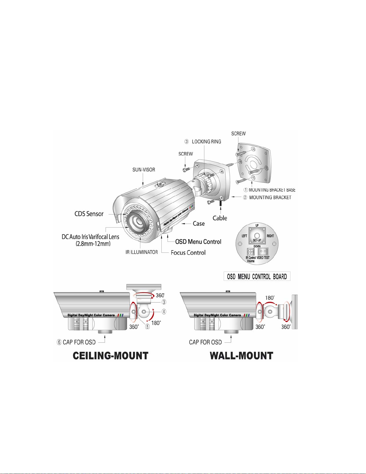
1. Attach the mounting bracket base① to the wall or ceiling, wherever you want to
install the camera. Locate a wall stud or ceiling joist and secure the bracket base①
using the supplied screws. Attach the mounting bracket② to the base① and secure
them using the supplied screws.
2. Lock the mounting bracket with the locking ring③.
3. Turn the pivot locking screw④ with the provided hex-head wrench counter-
clockwise to set the desired angle of camera toward objects and turn it clockwise to
secure. It can be used for wall-mount or ceiling-mount application depending on
setting this pivot locking screw.
4. Loosen the locking screw⑤ with the provided hex-head wrench and turn the camera
clockwise or counter-clockwise to upright images on the screen and turn it clockwise
to secure.
Page 3
5. If necessary, change the settings to get the best images depending on your application
by using the button on the bottom of the camera.
- Get rid of the cap⑥ for the OSD button by turning counter-clockwise and then
change the settings (refer to the included instruction manual for OSD Control).
- Turn the cap⑥ clockwise to secure after changing the settings.
6. Connect the one end of 100’ cable (supplied) to the BNC (F) of 5’ cable attached to
the camera and the other end (BNC) of cable to the video devices such as DVR,
monitor/TV. Plug the provided AC power supply to the DC jack (red) on the end of
100’ cable.
Page 4
HOW TO ADJUST ANGLE OF VIEW
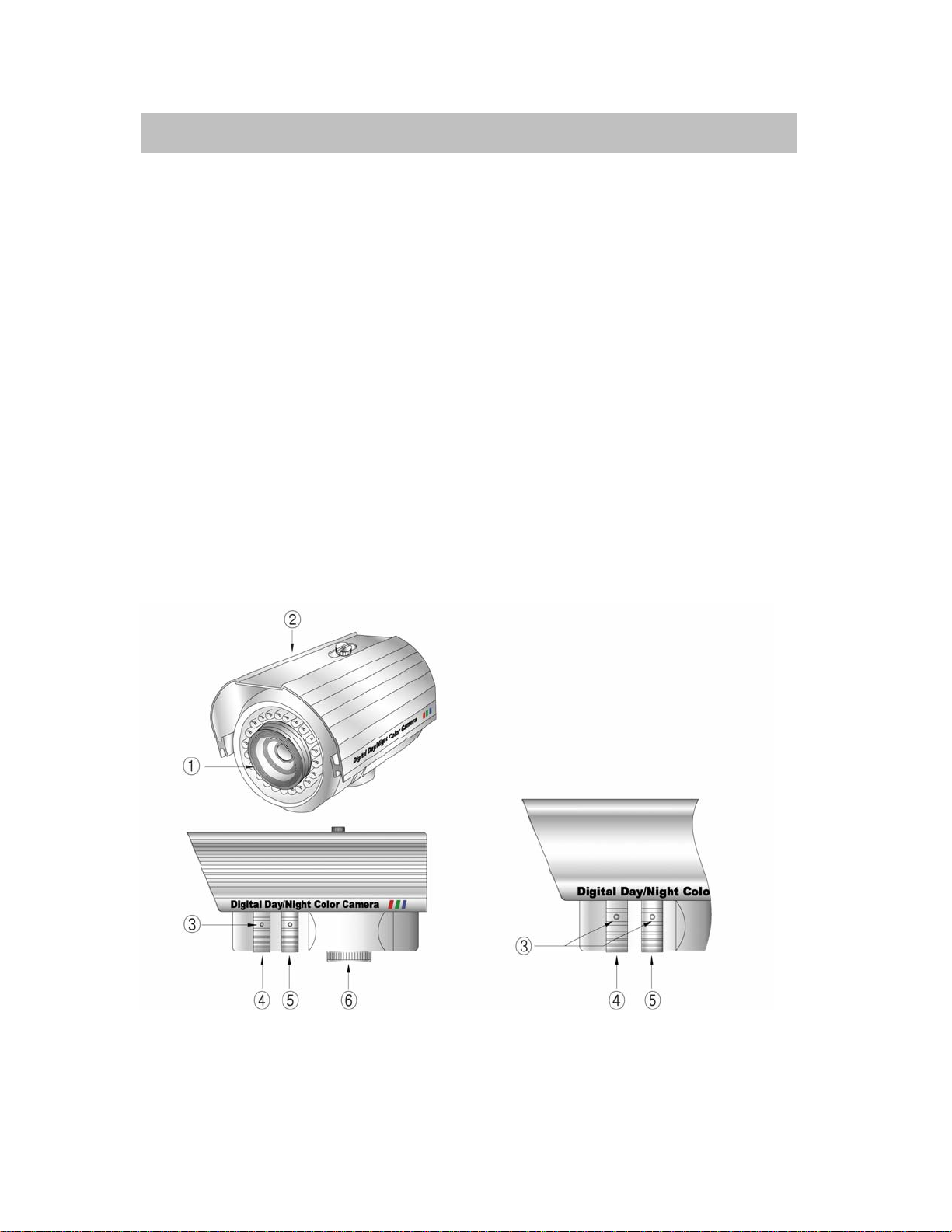
1. Vari-focal lens①
Easily changeable angle of view: 2.8 to 12mm
2. Remove the sun-visor② and turn the locking screws on the knobs③ with the
provided hex-head wrench counter-clockwise to make easier adjustment for angle of
view. Do not stamp your fingerprint on the lens and the window, which may affect
picture quality.
3. T↔W (Tele ↔ Wide)⑤
Turn this adjustment ring⑤ clockwise or counter-clockwise to set the focal length.
4. ∞↔N④
Turn this adjustment ring④ clockwise or counter-clockwise to set the focus.
5. After setting the focus and focal length, the locking screws on the knobs③ should be
securely fastened.
Page 5
Note:
g
▪ Apply the provided AC Power supply only.
▪ The total length of cable must not exceed 200’ includin
extension
cable.
TROUBLE SHOOTING
If the camera does not function properly, check the following points before contacting the
service center.
Troubles Remedies
No video Check the AC adapter and video cable
between the camera and a monitor
The image on the screen is dark Check the brightness control on the
monitor
The image on the screen is dim Check if the lens is stained. If dirty,
clean it with soft and clean cloth
The camera is not working properly, and
the surface of the camera case is hot
The contrast on the screen is too weak Adjust the contrast feature of the
The image on the screen flickers Does the camera face to directly to the
Picture rolls and jumps, scrambled
picture
Picture smaller than screen House current may be too low
SPECIFICATIONS
• Image sensor 1/3” SONY Super HAD CCD
• Total pixels 811(H) x 508(V)
• Effective Pixels 768(H) x 494(V)
• Scanning system 2:1 Interlace
• Synchronization Internal/Line Lock
• O.S.D Available
Check if you have connected the
provided AC adapter
monitor. If the camera is exposed under
too strong light, change the position
sunlight or fluorescent light? Change the
camera position
Improper V-hold control. Setting on your
monitor
Page 6

• Backlight Off / HSBLC / BLC selectable
• Resolution 550TV Lines(color),600TV Lines(B/W)
• S/N (Y signal) 52dB (AGC Off, Weight On)
• Min.illumination 0.00006Lux @F1.2 (sens-up:x258, IR LED:
ON)
• White Balance ATW / AWB / Manual / AWC→SET
• Sense-up Off / Auto / (Selectable limit x2 ~ x258)
• 3 DNR Off / On (1~50 level adjustable)
• D-WDR Indoor / Outdoor / Off
• D&N selection Color / BW / Auto
• Digital zoom On(x32) / Off
• Voltage AC 24V / DC 12V(Dual voltage)
• Current consumption LED On: 650 mA, LED Off: 180 mA
• Lens
• Operating temperature/Humidity -10°C ~ +50°C. RH 95% Max.
• Storage temperature/Humidity -20°C ~ +60°C. RH 95% Max.
• Dimensions 88 (W) x 105 (H) x 222 (D)mm
• Weight 3.2 Lbs
DC Auto Iris Varifocal Lens (2.8mm-12mm)
LIMITED 2 YEAR WARRANTY
This warranty gives the original purchaser specific legal rights and you may also have
other rights, which vary from state to state. If our products do not function because of any
defect in material or workmanship, we will repair free of charges for 2 years on parts and
labor from the date of original purchase. This warranty does not cover modification,
abuse, incidental or consequential damages unless the state of owner’s residence specially
prohibits limitations on incidental or consequential damages.
HOW TO OBTAIN FACTORY SERVICE
1. Original purchaser must fill out a warranty card and mail it to the factory with model
number, serial number and the date of purchase.
2. We will repair or replace, and return to the owner the system under this limited
warranty.
3. Please pack the system carefully and securely using the original packing materials,
and send it prepaid and insured to: 13073 E. 166th St, Cerritos, CA 90703.
4. Please include a check for $20.00 to cover the cost of return postage and handling. If
the system is returned within the warranty period, please include a proof of purchase.
If the system is out of warranty, you will receive an estimate of the repair cost for
your approval before repair work will be begun.
Page 7

AVAILABLE ACCESSORIES
CDR0460 Stand-alone 4 CH Digital Video Recorder (DVR)
CDR4450 Stand-alone 4 CH Digital Video Recorder (DVR)
CDR0860 Stand-alone 8 CH Digital Video Recorder (DVR)
CDR1660 Stand-alone 16 CH Digital Video Recorder (DVR)
CDR0850 Stand-alone 8 CH Digital Video Recorder (DVR)
CDR1650 Stand-alone 16 CH Digital Video Recorder (DVR)
CA100BP 100’ BNC/Power to BNC/Power Extension cable and coupler
PACKAGE INCLUDES
1-True Day & Night Color Camera
1-Universal Mounting Bracket & 100’ BNC/Power to BNC/Power cable
1-UL Approved AC Power Supply
1-Hardware Accessories Kit
1-Instruction Manual
1-Instruction Manual for OSD Control
1-Warranty Registration Card
 Loading...