

Page 1
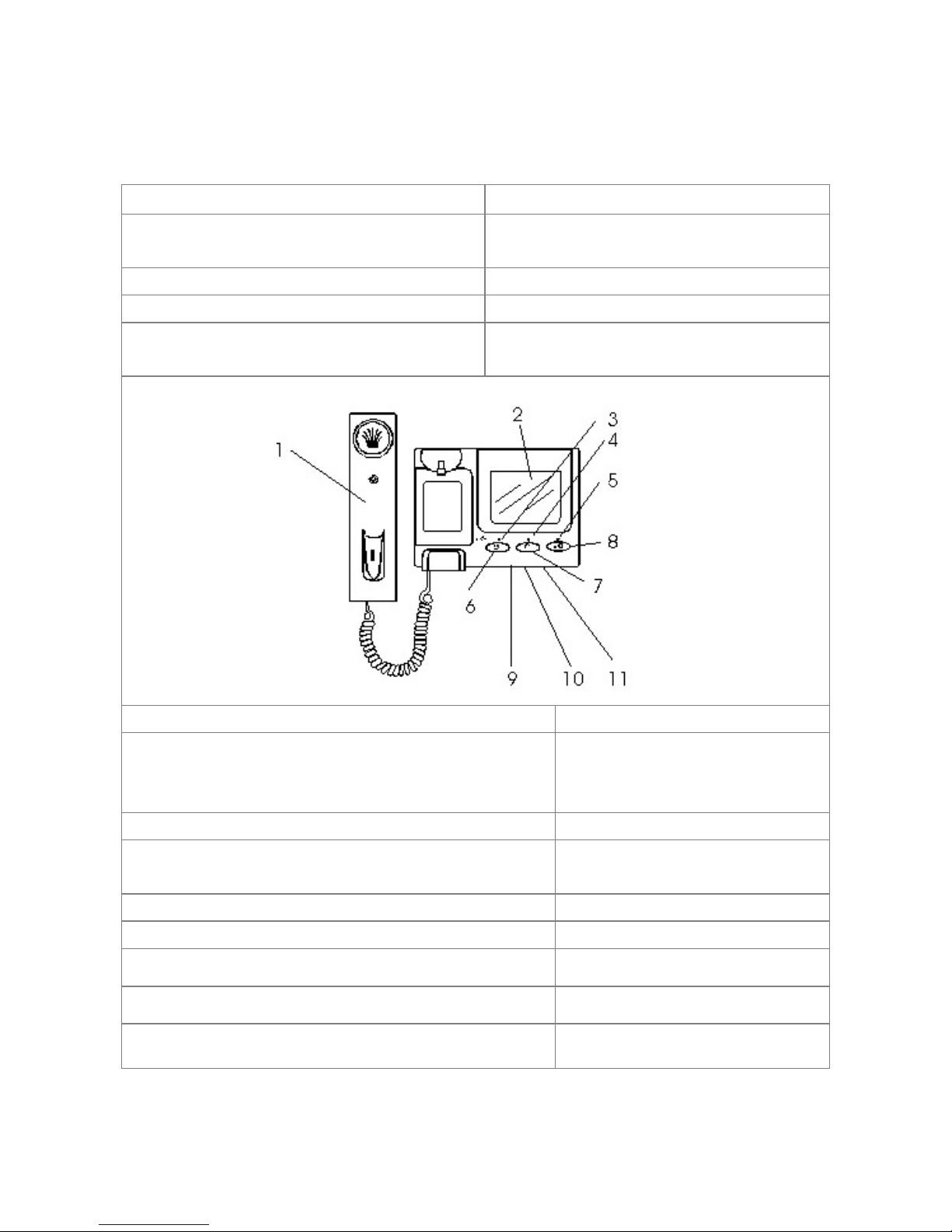
INDOOR MONITOR
1. Handset 6. Monitor Button
Lift to communicate with your visitors. Press this button to view the picture from
the camera
2. Monitor Screen 7. Call Button (intercom function)
4” color LCD-TFT Press this button to communicate with
monitor 2 or monitor 3
3. Power Lamp (Red) 8. Door Release Button
Indicate if the system is on or off Release the door to let your
visitors come in after viewing
them
4. Operate Lamp (Red) 9. Volume
Light on indicates operating Adjustment of the call sound
volume
5. Unlock Lamp (Red) 10. Brightness
Light on indicates unlocking E-lock Adjustment for image brightness
11. Contrast
Adjustment for image contrast
Page 2
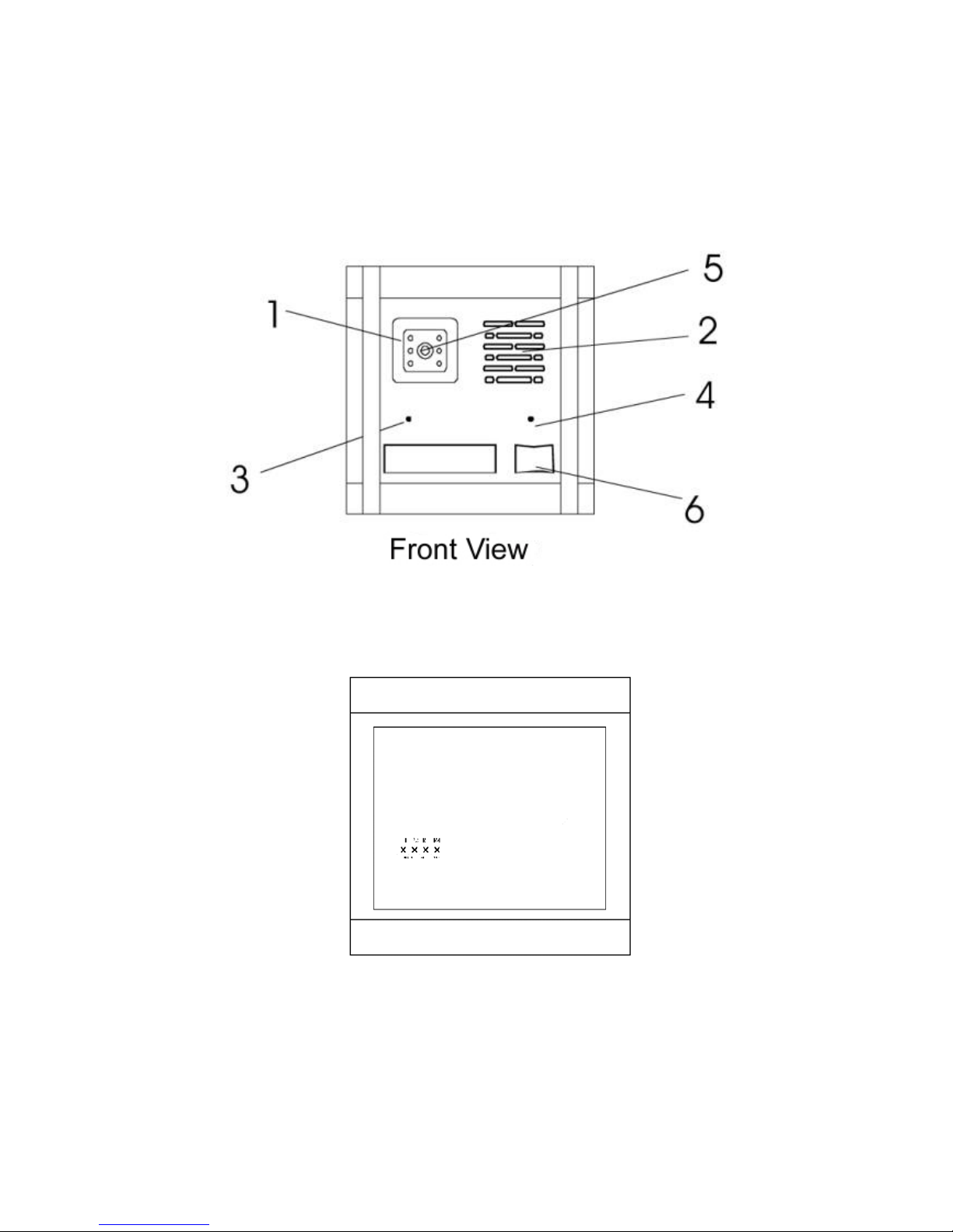
OUTDOOR CAMERA
Rear View
Page 3
Connector pin configuration
R1 Video output
R2 Ground
R3 Audio signal
R4 DC 13V – 14V
1. Super infrared LEDs
Let you see clearly even at night
2. Speaker
Broadcasts the voice from the monitor
3. Microphone 4. Optical sensor
Picks up the voice of the visitors Sensor for intensity of light
5. Camera 6. Call button
Picks up the image of the visitors clearly Chime “ding dong” sound can be heard
from inter-phone when this button is
pressed, and the camera start working
simultaneously
HOW TO INSTALL
1. INSTALLATION OF MONITOR
Page 4
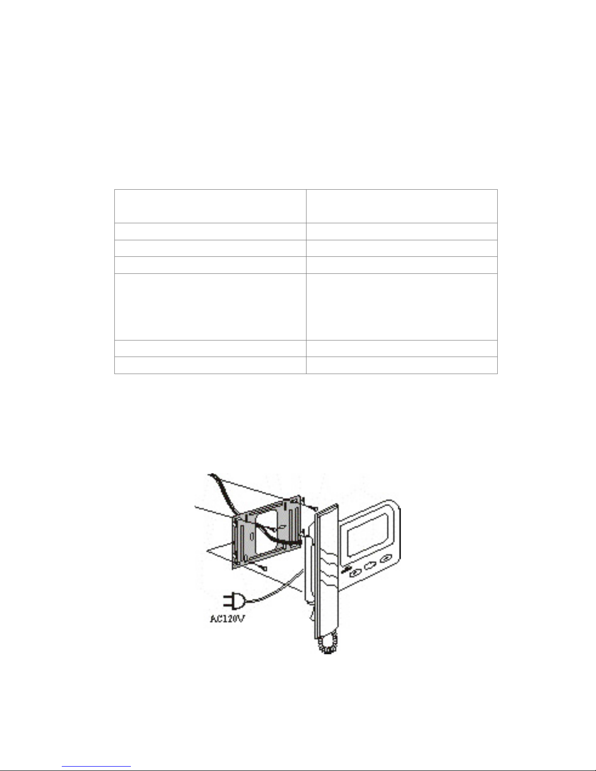
1. Attach the bracket to the wall to install the monitor. Secure the bracket with the
supplied screws.
2. Connect the cable connectors with 4 wires in polarity to the wafer on the rear of the
monitor.
3. Fasten the monitor onto the bracket
4. Connect the spring wire of handset
5. Plug the supplied 1A AC adapter to the DC IN jack on the rear of the monitor and
plug it into AC 120V outlet.
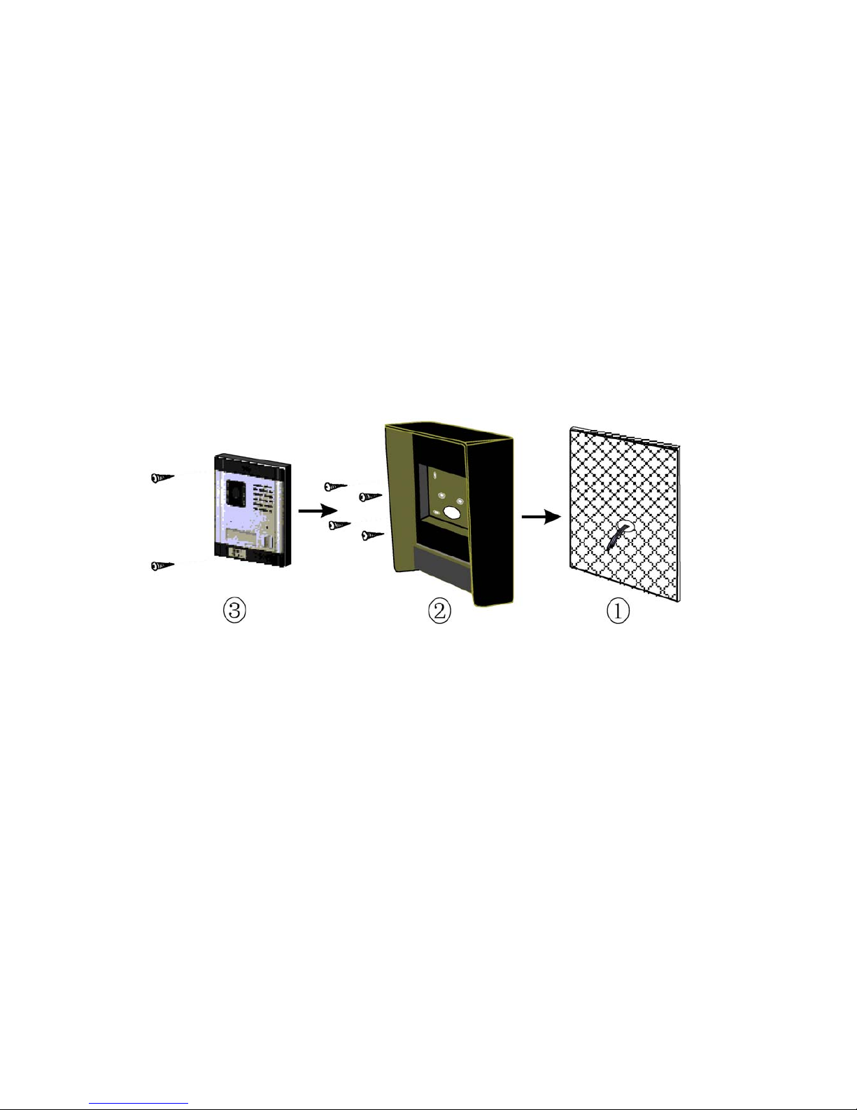
2. INSTALLATION OF CAMERA
1. Attach the visor (sun or rain) to the wall to install the camera. S ecure the visor with
the supplied screws (Refer to the above illustration).
2. Connect the cable connectors with 4 wires in polarity to the wafer on the rear of the
camera.
3. Install the camera onto the visor with the supplied screws.
 Loading...