


Please read the “User’s Guide” to use the product correctly.

USER’S RECORD
MAC Address is indicated on the bottom side of the product.
Record MAC Address in the space provided below.
It is necessary to keep it when using Service that is Dynamic DNS server of
Technical Support & Clover Electronics U.S.A.
MAC Address: 0 0 – 0 8 – F 2 - - -

- 1 -
User’s Guide
Pan/Tilt Network Camera
All rights reserved by Clover Electronics Inc. ; no part of this publication may be reproduced,
stored in a retrieval system, or transmitted, in any form or by any means, electronic, mechanical,
photocopying, recording, or otherwise, without the prior written permission of the publishers
This user’s guide explains how to install and use the PAN/TILT NETWORK CAMERA. For
further inquiries or information in more details, please refer to the product web site or contact the
local agent.
This user’s guide is based on Firmware Version [2005/02/25 E1 NO], Client Version [2.2.9] and all
information including the product specification is subject to changes without any notice.
System Requirement
Network: 10 Base-T LAN
Client PC: Pentium III 500 MHz or more, Memory (RAM)-128MB or more
Web Brower: Microsoft Internet Explorer 5.5 or more (This product is optimized for Internet
Explorer 6.0)
O/S: Windows 98/Me/2000/XP
PC Monitor Resolution: 1024x 768 pixel or more.
TECHNICAL SUPPORT
For technical problems on usage or warranty, please contact local agent or visit our product web
site. The latest technical resources or upgraded version of Firmware should be followed up
regularly.
Company Web site: http://www.cloverusa.com
Technical support and warranty:
Main office: 13073 E. 166th St. Cerritos, CA 90703 U.S.A.
TEL) +1-562-282-3900 FAX) +1-562-282-5900
. . . . . . . . . . . . . . . . . . . . . . . . . . . . . . . . . . . . . . . . . . . . . . . . . . . . . . . . . . . . . . . . . . .
Before start

- 2 -
User’s Guide
Pan/Tilt Network Camera
FCC statement (USA)
The United States Federal Communications Commission (FCC part 15.105) has specified that
the following notice be brought to the attention of users of this product:
This equipment has been tested and found to compl
y
with the limit for a Class A digital device,
pursuant to part 15 of the FCC Rules. These limits are desi
g
ned to provide reasonable
protection a
g
ainst harmful interference when the equipment is operated in a commercial
environmental. This equipment
g
enerates, uses, and can radiate radio frequency energy and, if
not installed and used in accordance with the instruction manual, ma
y
cause harmful
interference to radio communications. Operation of this equipment in a residential area is likel
y
to cause harmful interference in which case the user will be required to correct the interference
at his own expense.
Warning
This is a class A product. In a domestic environment, this product may cause radio
interference in which case the user may be required to take adequate measures.
User’s Information (‘A’ grade device)
This product is for business use only. Please select the right product accordin
g
to the
use. If you are using it at home, it is necessary to exchange the product for domestic
use.
. . . . . . . . . . . . . . . . . . . . . . . . . . . . . . . . . . . . . . . . . . . . . . . . . . . . . . . . . . . . . . . . . . .
Approval

- 3 -
User’s Guide
Pan/Tilt Network Camera
z Do not disassemble or remodel
if any problem occurs while using the product, contact the agent for repair. Do not attempt to
repair it by yourself.
z Use the appointed power supply only
Incorrect power supply can damage the product. Use an adaptor provided by manufacturer
and, exchanges it at a local agent if damaged.
z Where to install;
- It is designed to be used only indoors where the room temperature is between 5C and 40C
- Avoid places high in moisture
- Avoid places with intense lighting
- Avoid direct sunlight.
- Avoid any exposure to gas or oil.
- Avoid dusty areas.
- Avoid places with strong electro-magnetic force
z Do not put the camera faced towards sunlight or electric light
It can cause critical damage to CCD device.
z Do not touch or wipe lens
Make sure you do not leave fingerprints on lens.
z Handle with care when carrying or installing the product
Strong shock or vibration can damage the product.
z In case of using outdoors, it is necessary that the product is kept in a waterproof and
insulated case to keep moisture-free and room temperature.
This product is designed for indoor use so it must be put in the special case provided.
. . . . . . . . . . . . . . . . . . . . . . . . . . . . . . . . . . . . . . . . . . . . . . . . . . . . . . . . . . . . . . . . . . .
CAUTION
To prevent any damage or accident due to mishandling the points mentioned above
regarding to safety must be followed. Make sure to read them before installin
g
the
product. Clover Electronics Co Ltd is not responsible for an
y
damage or incident
occurred due to negligence of the safety points or caution

- 4 -
User’s Guide
Pan/Tilt Network Camera
Summary and Main Features 5
Components of product 7
Before Use 10
Installation 10
Checkpoints according to network type 11
Internet service environment and DNS Server 13
Connection of camera and IP s et-up 13
Connection 13
Camera IP setup using setup IP program 14
Camera IP setup using temporary IP address 17
Camera setup of private network using Router and port-forwarding method 21
Terms of Web page and Functions 23
(Section 1) Preset 25
(Section 2) Patrol 27
(Section 3) Sensor 28
(Section 4) Video 29
(Section 5~7) Display Area, Admin Tools, Connect/Disconnect 30
(Section 8) Select View Mode, (Section 9) Motion Control 32
(Section 10, 11-1) Alarm I/O, Position 33
(Section 11-2, 11-3) Status, Record 34
(Section 11-4) Still image 35
(Section 11-5, 11-6) Video Player, Sound 36
(Section 11-7, 11-8, 11-9, 12) MIC, Stretch, Zoom, H.323 Mode 37
Set up of Admin Tools 38
Video & Audio 38
Network 41
System 45
Motion Detection 48
Sensor 50
FAQ 51
[REF 1] Appearance of product 53
[REF 2] Camera Set-up 54
[REF 3] Disassembly of Camera 56
[REF 4] Firmware Update 57
[REF 5] Set-up of Different types of routers 60
[REF 6] Terms and functions of Alarm I/O Module 67
[REF 7] Factory Default Value 70
[REF 8] Specification 72
. . . . . . . . . . . . . . . . . . . . . . . . . . . . . . . . . . . . . . . . . . . . . . . . . . . . . . . . . . . . . . . . . . .
Table of contents

- 5 -
User’s Guide
Pan/Tilt Network Camera
What is PAN/TILT NETWORK CAMERA?
PAN/TILT NETWORK CAMERA has a web-server H.323 protocol stack built-in itself, which
enables it to transmit images and sound simultaneously and to connect between H.323 and
compatible terminals or between S/W. Also it has Pan/Tilt mechanism that detects both position
and speed of an object so that it is possible to monitor in all directions. As a result, PAN/TILT
NETWORK CAMERA can be set up and used by simply connecting the network lines to power
supply without additional devices or programs.
Application diagram
Related Software
. . . . . . . . . . . . . . . . . . . . . . . . . . . . . . . . . . . . . . . . . . . . . . . . . . . . . . . . . . . . . . . . . . .
Summary and Main Features
- SecuEyes-MV16 Lite (Multi-Viewer)
: A program capable of monitoring up to 16 cameras at the same time
- SecuEyes-MR 16 (Multi-Viewer & Recorder)
: A program capable of monitoring and recording up to 16 cameras at the
same time
- SecuEyes mV1 (PDA Viewer)

- 6 -
User’s Guide
Pan/Tilt Network Camera
Main features
z Built-in Web Server & Web interface
It has built-in Web Server that transmits image and sound data in real-time through the
network, and without any additional program, an access to the server via Web browser such
as MS Explorer is available.
z High Speed/Wide Range Pan & Tilt Motion
It monitors with adjusting speed in 10 stages and a rotating range of 320° horizontally, 105°
vertically. Therefore no blind spot occurs.
z Higher Frame Rate & Lower File size
By compressing image data transmitted by H 263 codec, it generates transmission speed of 25
frame per second (SIF standard) or higher.
z Bilateral sound communication
Sound codec of G.723.1 is used and bilateral sound communication is possible.
z H.323 internet video phone
It is possible images and voice via H323 Internet video phone and view images at different
angles. ( Only the Internet video phone specified by the company should be used)
z External Camera can usage Network Camera
Connecting CCTV camera with an external camera makes an additional network camera.
z Flash Memory for Firmware update
It is convenient to upgrade built-in software of camera to the latest version through web
browser.
z Multi-Viewer Software & Multi-User Connection
It monitors and controls four network cameras at the same time and up to 15 persons can get
an access to a camera at the same time. (The number of persons on-line at any time can vary in
future).
z Alarm I/O and function of Motion Detection
When operating external sensor, it controls external ON/OFF device as it moves in preset
positions and transmits recorded images through registered E-mail. Also motion detection can
function as external sensor.
z DDNS Server Support
Registering Service from our DDNS server when the camera is equipped in mobile IP
environment entitles each camera with a domain name and allows to be used as fixed IP.
z 10 Position Preset & Auto Patrol
10 Camera position and alarm output condition can be preset and it auto-patrols repeatedly
following specified positions in order.

- 7 -
User’s Guide
Pan/Tilt Network Camera
Item check
Please make sure all the items listed below are contained before use. If not, contact the agent
where the product is purchased for any missing items.
Components of product
No. Item Description
1 Pan/tilt network camera Camera network unit
2 Ceiling Mount Set Ceiling Plate and bolts
3 Rear Cover Camera cover
4 AC Adapter 100~240VAC, 50/60Hz
5 Power Code AC Adapter connection.
6 Multi-Port Cable Video Out, Audio In/Out port
7 Cross-Over Cable Camera IP setup cable (red, 2m)
8 Clamp Filter for EMC Suggestions from EMC test result
9 Setup CD-ROM Setup IP, User’s guide...etc.
. . . . . . . . . . . . . . . . . . . . . . . . . . . . . . . . . . . . . . . . . . . . . . . . . . . . . . . . . . . . . . . . . . .
Components of product
Network Camera
Ceiling Mount Set
Rear Cover
AC Adapter
AC Cable
Multi-Port Cable
Cross-Over Cable
Clamp Filter
Setup CD-ROM
- 8 -
User’s Guide
Pan/Tilt Network Camera
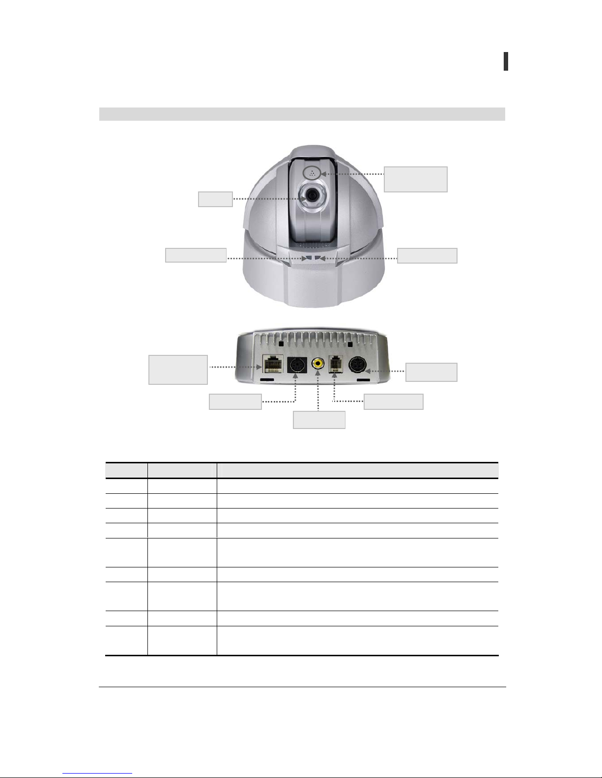
Name of parts
No. Item Description
1 Lens Fixed lens. Default: F 6.0mm, Option: F 3.8mm
2 Power LED Displaying red light when power is on.
3 Action LED Flashing green light when using LAN service.
4 LAN Port Connecting10 Base-T LAN cables
5 Power Code
Connect to AC Adapter.
(Use acceptable voltage in different country.)
6 Multi-Port Audio In/Out, Video Out.
7 Video IN
Connecting the external CCTV Camera can be used as External
Video Source of network camera.
8 Alarm I/O Connect to Alarm I/O Module (Optional)
9 Power
Use AC Adaptor. Input power is AC100V~AC240V and output
power is DC 3.3V/5V/12V
Internal
micro
p
hone
Lens
Power LED
LAN Port
(10 Base-T)
Multi Port
Video IN
Alarm I/O
Power
- 9 -
User’s Guide
Pan/Tilt Network Camera
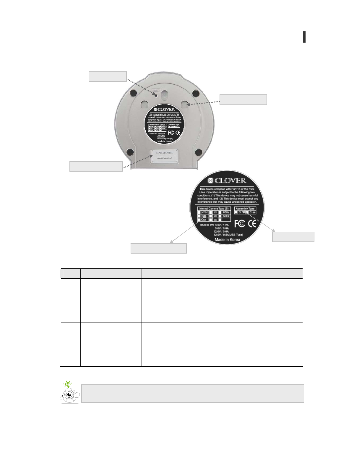
No. Items Descriptions
1 Factory Reset
The product setting condition should be the same as when its
being consigned. When camera is on, wait 10 seconds then
press reset button short while.
2 MAC Address Label MAC Address is indicated
3 Ceiling Plate Hole A matching-hasp of the Ceiling Plate
4 Internal Camera Type
Information including TV Type, pixels (270,000/410,000), AC
Power Frequency, when consigned, are indicated in detail.
5 Assembly Type
Explains how Internal Camera is to be assembled in terms of
bearings and angles; two assembly types - Desktop (D) and
Ceiling(C) – available.
Internal Camera Type
Assembly Type
Video image is displayed upside down when set up as desktop, therefore it is
necessary to get desktop assembly type when purchasing camera.
Ceiling Plate Hole
Factory Reset
MAC Address Label
<Bottom View>
- 10 -
User’s Guide
Pan/Tilt Network Camera
Set-up procedure
In order to set up a network camera, please refer to the following procedure.
1 Make sure the type of network currently used and details to be inspected before set up (refer
the manual in pages 12~13)
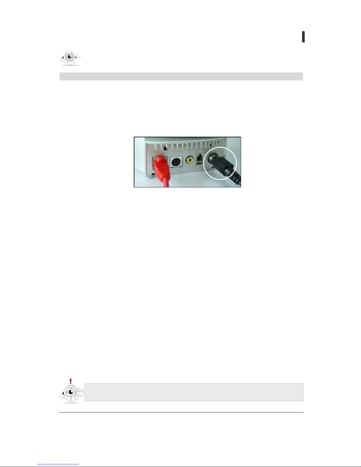
2 Connect AC Adapter and power cord to power terminal of camera.
3 Connect LAN ports of both Camera and PC directly with Cross-Over cable or connect to the
Internet or LAN with Direct cable
(Refer to text in page 14)
4 The following methods should be considered when allocated IP address of camera is not
identified in dynamic IP environment.
- Set up SMTP from administrator’s page and receive by E-mail. (refer to text in page 43)
5 IP address can be set using two methods.
A. Establish camera IP using automatic IP setting program (Setup IP Software).
(Refer text in page 15-17)
B. Establish camera IP using IP address set by manufacturer temporarily
(Refer text in page 18~20)
6 Set up camera in an appropriate place and then connect power and LAN
(Refer text in pate 54~56)
7 If installed interior private IP network using router, set up port-forwarding that is high-quality
function of router. (refer text in page 21~22)
. . . . . . . . . . . . . . . . . . . . . . . . . . . . . . . . . . . . . . . . . . . . . . . . . . . . . . . . . . . . . . . . . . .
Before use
All products are set with same IP address when manufactured, IP address must be
chan
g
ed after purchase. (192.168.1.1~3 must be not be used)
- 11 -
User’s Guide
Pan/Tilt Network Camera
Items to be confirmed before set up by network type
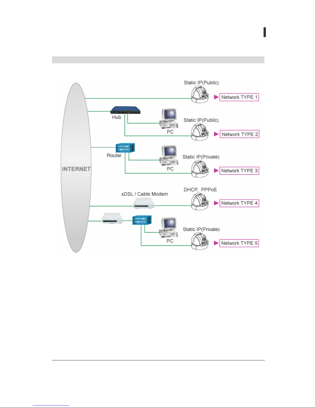
1. Before installing network camera, confirm user’s network type
A. Static IP(Public) : it is a Network component that is given Static (Public) IP from Internet
service provider (Cable, Private line)
i. Network TYPE 1, Network TYPE 2
ii. Make a note and confirm Static (Public) IP given by internet service provider and other
network environment information.
B. DHCP, PPPoE: it is a Network component set up exterior type xDSL(PPPoE) or Cable
Modem and given dynamic IP.
i. Network TYPE 4
ii. Make a note of user ID and password for xDSL connection when using PPPoE of xDSL
service

- 12 -
User’s Guide
Pan/Tilt Network Camera
C. Static IP (Private): it is a network that has several Static (private) IP addresses with one Static
(public) IP address. Using general IP router, it composes into interior private IP network
environment
i. Network TYPE 3, Network TYPE 5
ii. Make up interior private IP network environment first using router manual
iii. Select private IP Address, Web Server Port and Video Server Port for camera.
iv. Web Server Port and Video Server port imagination server or Port-forwarding that is an
advanced function of router
- 13 -
User’s Guide
Pan/Tilt Network Camera
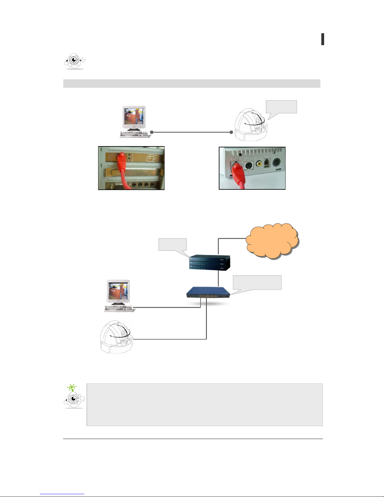
Connection
Method 1) Connect camera to PC directly
Method 2) Connect camera to the internet or LAN
Cross-Over Cable
Camera
Internet
10 Base-T HUB
Router
Direct Cable
Direct Cable
What is Cross-Over Cable? Cross-Over Cable (Red Color Cable, 2M) is used when
connecting camera into PC directly without hub.
What is Direct Cable? Direct Cable is
g
enerally used LAN Cable when connecting
with hub.
Camera connection and IP set-up
. . . . . . . . . . . . . . . . . . . . . . . . . . . . . . . . . . . . . . . . . . . . . . . . . . . . . . . . . . . . . . . . . . .
- 14 -
User’s Guide
Pan/Tilt Network Camera
Set up camera IP using Setup IP program
1. Characteristic and caution to Setup IP program
A. Setup IP Software (Version 2.0.0.2) only operates in Static IP set-up mode. In case the
camera has been set up in Dynamic IP or/and PPPoE mode, it is advised that the camera is
to be initialized to the Static IP using the factory Reset.
B. If Camera Firmware is a year 2003 patched version it is recommended to update to year
2004 patched version or use Setup IP Software Version 1.0.
C. Complete all settings within 5 minutes because item is deleted automatically in program list
If 5 minutes are passed after camera booting
D. Check for User setting value
i. Web Server Port (TCP): If not 80, it should be bigger than 1024 and smaller than 65535.
(Default: 80)
ii. Video Server Port (TCP): If not 4333, it should be bigger than 1024 and smaller than
10000. (Default: 4333)
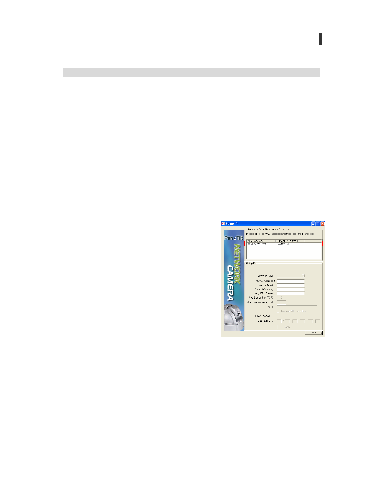
2. Set-up procedure
A. Download Setup IP Software when connecting
camera with PC Connect power and LAN into
camera
B. Execute Setup IP downloaded in PC
C. After camera booting (10 sec) MAC Address and
temporary IP of camera are marked in <Scan the
Pan/Tilt Network Camera> area on top of the
program
D. If you click MAC Address, temporarily given
network information is marked in Setup IP portion
of program.
E. Enter network information that you wish to set up
F. If click [Apply] button, setting is completed.
3. Setting method by Network Type
A. Static IP
i. Internet Address: Enter IP information given by internet service provider or network
manager.
ii. Subnet Mask, Default Gateway: Subnet Mask, Default Gateway: Enter information that
is given with IP information. Generally it is identical with the value that is established in
PC.

- 15 -
User’s Guide
Pan/Tilt Network Camera
iii. Primary DNS Server: Enter DNS Server
provided by Internet Service Company. Refer
text 13 Pages
iv. Web Server Port (TCP/IP): It is a port for Web
Page of camera and data communication.
v. Video Server Port(TCP/IP): It is a port for
Video of camera & Audio data
communication
B. Dynamic IP(DHCP)
i. Use when connecting with Cable Modem or
automatic connection modem.
ii. Set up Web Server Port and Video Server Port
C. PPPoE
i. Use when setting up bridge mode of xDSL
Modem or automatic connection modem.
ii. Set up Web Server Port and Video Server Port
iii. User ID ; Can have up to 20 characters in English,
and when "Use Over 20 Characters" maximum 35
iv. User Password: Up to 20 characters of user
password
- 16 -
User’s Guide
Pan/Tilt Network Camera
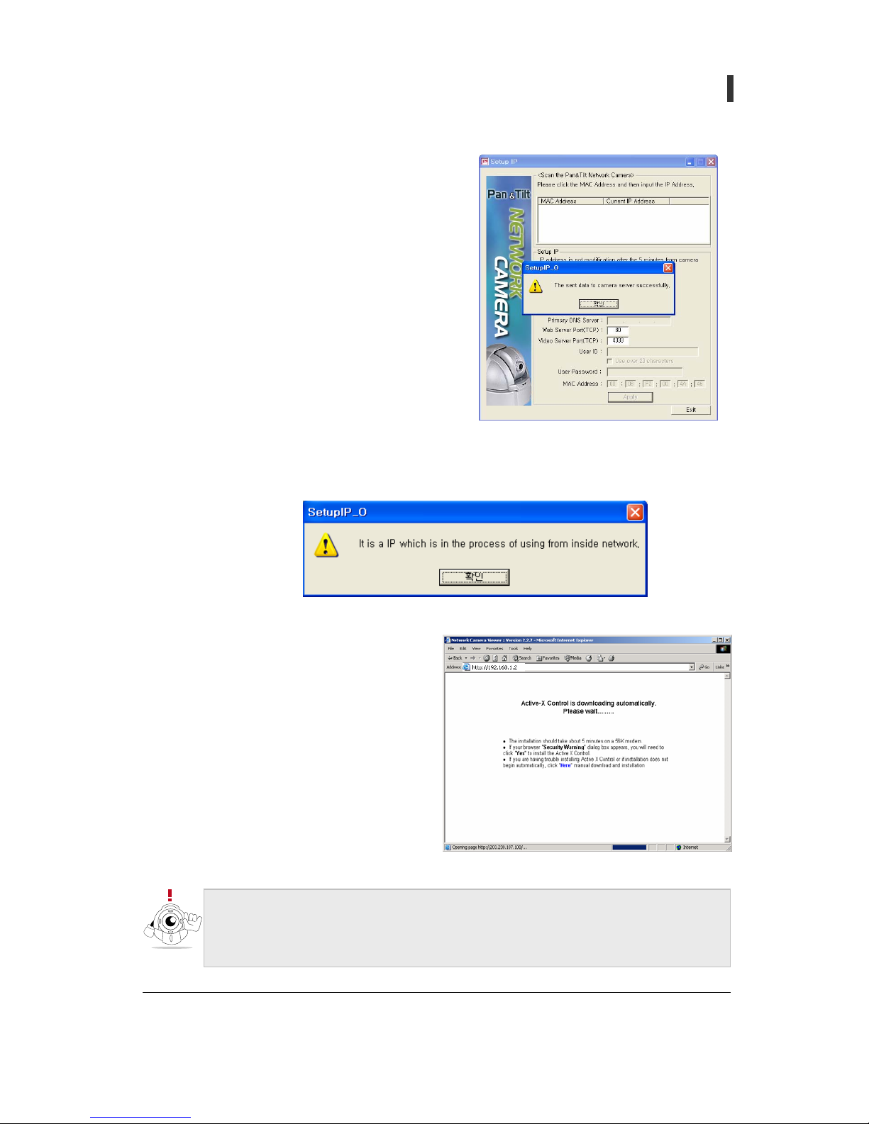
D. After completing camera setting normally,
success message window is created as shown in the
diagram when click [Apply] button click Confirm]
and finish setting.
E. Error message is displayed as follows in case it is set up by IP that exists in local area
network then you need to set up again.
4. Connect to Camera
A. Enter camera IP address in Internet
Explorer's address input space.
B. Download Active X Control
automatically.
C. Active X Control capacity is about 1.8M
so that downloading can take a some
time depending on network state
D. If security certification window rises,
click [yes (Y)].
z You must retry booting the camera if failed in setting in 5 minutes after booting.
z If securit
y
certification window does not rise after connection to camera, confirm
whether Internet Explorer's tool> internet option> securit
y
items are set up in
[normal].
- 17 -
User’s Guide
Pan/Tilt Network Camera
Setting up camera IP using temporary IP address
1. For Windows 98
A. Double click on Start-> set-up-> control-> network
B. After click "TCP/IP" in network window, click [register] button.
C. After selecting (IP address), enter network information as shown on the diagram to
[allocated IP address use].
D. Select (gateway) after entering "192.168.1.1".
E. Click (OK) button
F. If IP setting is changed, it re-sets Windows composition and can request for Windows98 CD.
After insert CD in CD-ROM drive, click [OK] button. file copy is done , re-boot computer
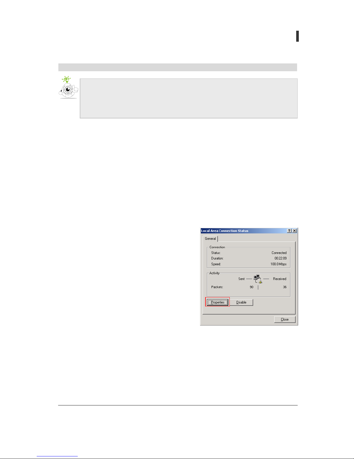
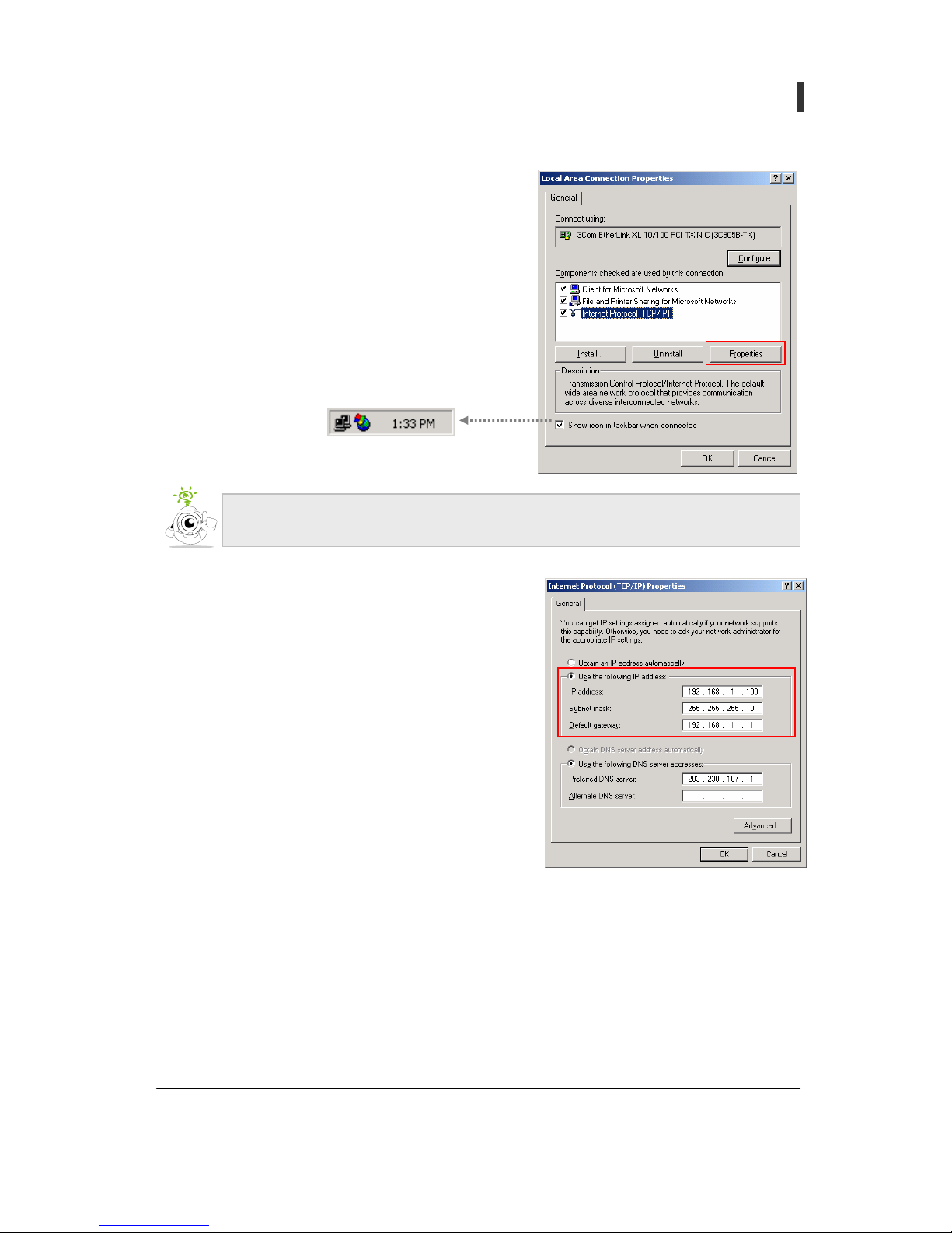
2. For Windows 2000/XP
A. Click start-> setting -> control-> network and
phone connection-> local area connection
B. Click (Properties)
Change Internet Protocol (TCP/IP) of PC to connect into camera as following.
z IP Address: 192.168.1.11
z Sub Net Mask: 255.255.255.0
z Gateway: 192.168.1.1
- 18 -
User’s Guide
Pan/Tilt Network Camera
C. Click “internet protocol (TCP/IP)” then click
(Properties)
.
D. Enter network information in [Use the following IP
address] as on the window.
E. Click the [OK] button.
Make a tick for”when linked, indication of icon on task bar,” network icon is shown
on the right below (tray icon) of PC screen
- 19 -
User’s Guide
Pan/Tilt Network Camera
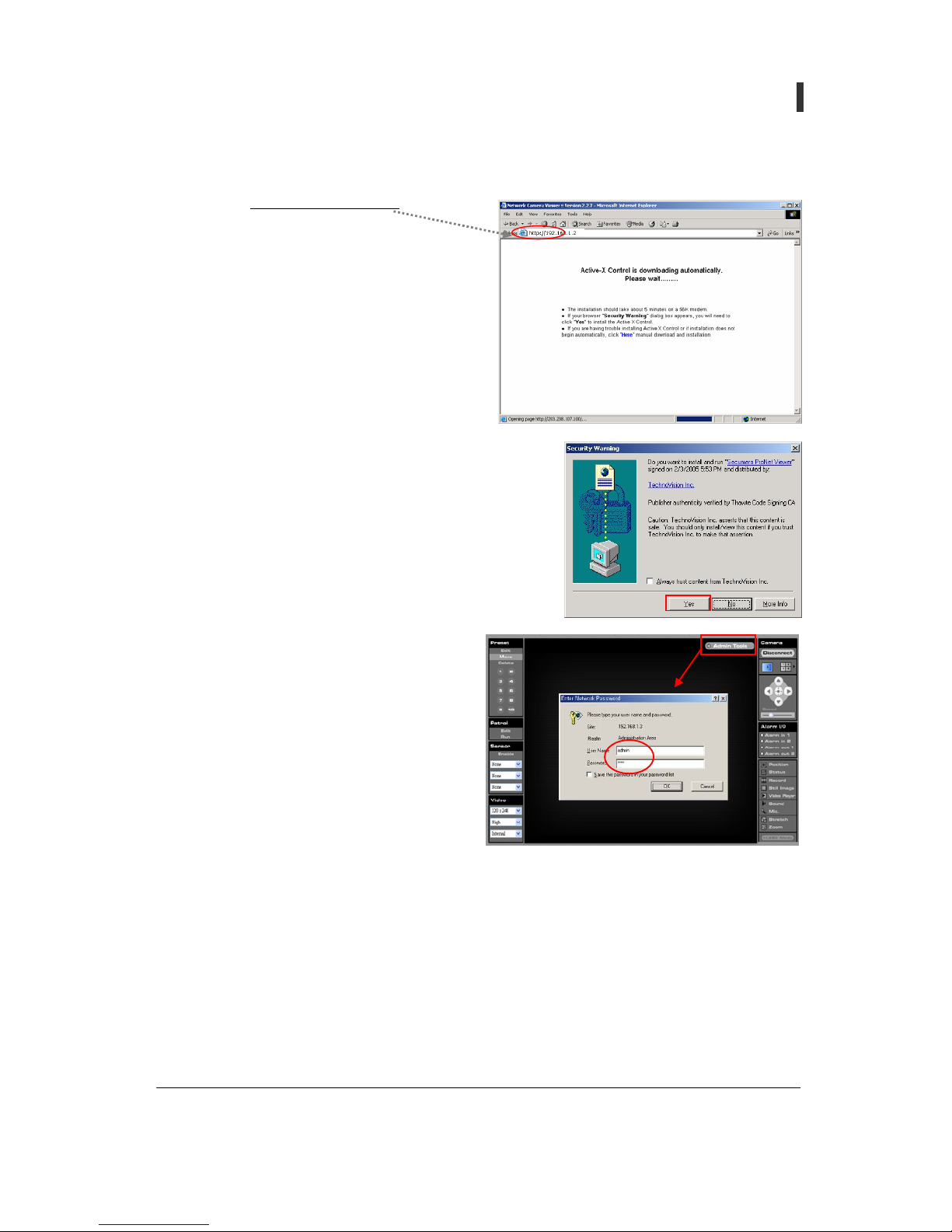
3. Connect to camera
A. Type 'http:// 192.168.1.2 /
' in Internet
Explorer's address
B. Download Active X Control automatically.
C. Active X Control capacity is about 1.8M so
that downloading can take a sometime
depending on network state. (Confirm
whether Internet tool Æ internet optionÆ
security item of Explorer's pull-down
menu are set up in (normal) )
D. If Active X Control download ends, wait for user’s
acceptance as "Security warning" window is created.
Click [yes (Y)] button for permission.
E. Connect to camera and click Web Page's
[Admin Tools] button and connect on
administrator’s page. Administrator
connection account ID: Admin, PW:
pass and refer to "Users" of text page 71
~ 72 "[reference 7] Factory Default
Value”
- 20 -
User’s Guide
Pan/Tilt Network Camera
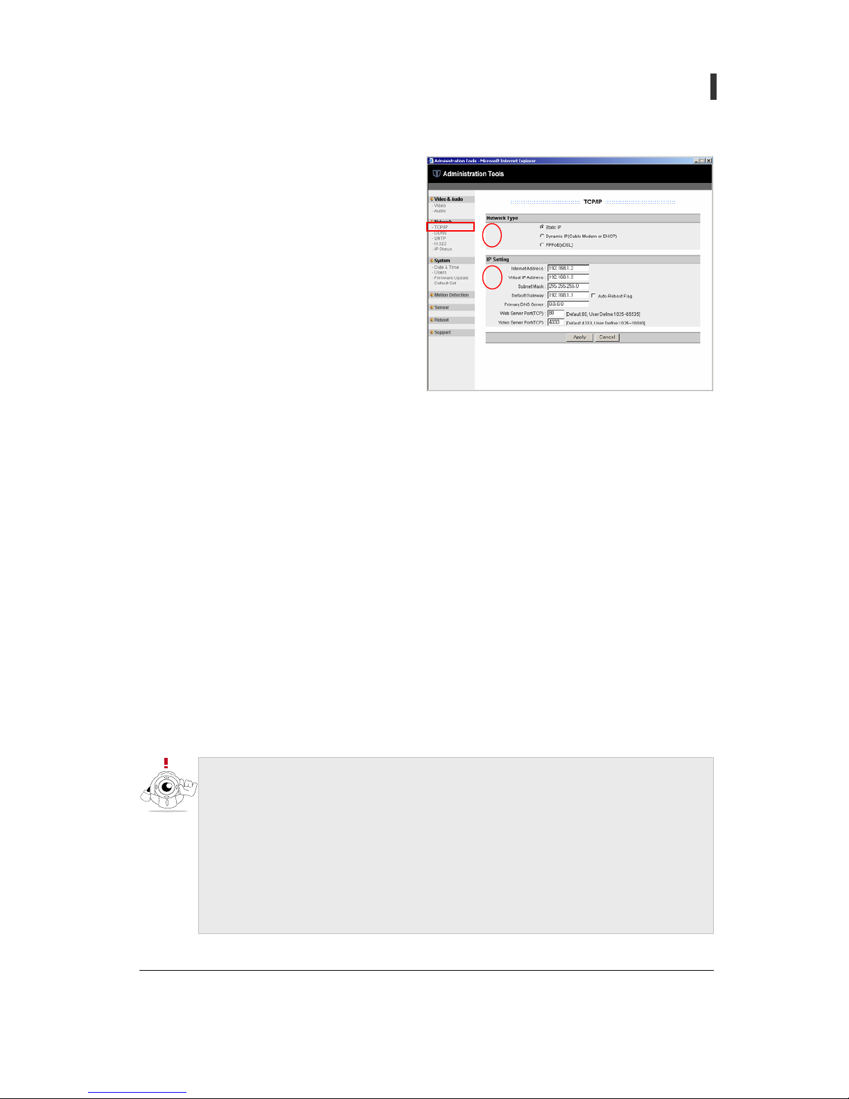
F. When Administrator page is open
click [TCP/IP] of [Network] group on
the left side menu.
G. After selecting Network Type (1), set
up IP Setting (2). Refer to text page 41-
42 for detailed setting method and
comment.
H. Click [Apply] button to finish setting.
I.
1
2
Virtual IP Address is given to camera for emergency connection and it should not be
changed to be used in following cases
- Do not know IP Address of camera
- Change to other network type (Static IP, PPPoE) after setting camera to D
y
namic
IP(DHCP) (it is possible to connect in 1 min 10 sec after connectin
g
power and
Cross-Over cable)
- Change to other Network Type (Dynamic IP, PPPoE) after settin
g
camera to
PPPoE. (it is possible to connect in 30 sec after connecting power and Cross-

- 21 -
User’s Guide
Pan/Tilt Network Camera
Camera setting and port-forwarding method in private network using IP Router
1. Camera set-up
A. Network Type: Static IP
B. IP Setting
i. Internet Address: 192.168.1.51
ii. Virtual IP Address: Do not change. But it can be changed to IP Address of other grade in
case installing several cameras at the same time to one IP Router because Virtual IP
Address is collided. (For example : 192.168.0.3)
Assume that network structure of above picture is set up as follows.
z Internal connection IP Address of Router: 192.168.1.1
z Private IP Address of camera: 192.168.1.51
It is better to set Gateway of camera with intra-connection IP Address of IP router and
also set remaining network information according Gateway

- 22 -
User’s Guide
Pan/Tilt Network Camera
iii. Subnet mask: 255.255.255.0 (Follow IP router’s setting)
iv. Default Gateway: 192.168.1.1 ( enter intra-connection IP Address of IP router)
v. Primary DNS Server: enter DNS Server of internet service provider
vi. Web Server Port(TCP): 2051 ( it is recommended to add 2000 to the end number of IP
Address and you can assign other port of number 1025 ~ 65535)
vii. Video Server Port(TCP): 3051 (it is recommended to add 3000 to the end number of IP
Address and you can assign other port of number 1025 ~ 10000)
2. Port-forwarding set-up of IP Router
z Network that has one public IP address constructs local network that has many private IP
address using ordinary IP Router. when appliances with private IP address communicate
with the outside IP Router of this network structures changes private IP address to public
IP address and then connects with the outside (this function is called NAT (Network
Address Translation)Also, to be used as a server, appliances with private IP address must
use port forwarding function of IP Router. Port forwarding is a function to deliver a
request (internal Port) that enters to specific port from the outside to appliances (PC,
network camera) with internal private IP address.
z It is a [port forwarding] setting table of high-quality function of router
z Refer to text Page 61 ~ 67 “[reference 5] router models by different manufacturers and
port forwarding setting method".
No. Service Protocol Service Port Internal Port Internal IP Address
1 TCP 2051 2051 192.168.1.51
2 TCP 3051 3051 192.168.1.51
After changing web server port, enter by following method to connect to camera
z Port no. 80 : http://192.168.1.51
or http://192.168.1.51:80
z 2051 Port no. 2051 : http://192.168.1.51:2051

- 23 -
User’s Guide
Pan/Tilt Network Camera
Section Name Description
1 Preset
It can move camera immediately to specified position that stored in
advance by user. Position and speed of camera and Alarm Out state are
stored and maximum of 10 can be specified to Preset.
2 Patrol
It makes camera patrol automatically between the preset positions
3 Sensor
It interlocks Preset and action of sensor that is installed to Input terminal
of Alarm I/O module that is linked to camera.
4 Video Set up Resolution of image, Quality, and Camera Source
5
Display
Area
Image of camera appears in 1 Channel/4 Channel
6
Admin
Tools
Connect on administrator page of camera. When connecting,
Administrator’s account details (ID: Admin, PW: Pass) needs to be entered
and main function and environment of camera can be set.
7
Connect/
Disconnect
Connect or disconnect to camera that is registered to Server Manager.
8
Select View
Mode
Can select Single View Mode (1 channel) and Multi View Mode (4
channels).
9
Motion
Control
It Can regulate the speed of camera by 10 steps using Jog button that makes
camera move in all direction (up/down/left/right/center) and slider bar
(1)
(2)
(3)
(4)
(7)
(9)
(12)
(10)
(11)
(5)
(6)
(8)
. . . . . . . . . . . . . . . . . . . . . . . . . . . . . . . . . . . . . . . . . . . . . . . . . . . . . . . . . . . . . . . . . . .
Name of web page and function

- 24 -
User’s Guide
Pan/Tilt Network Camera
10 Alarm I/O Mark Alarm Input state, and control Output terminal On/Off
11
Function
(Toggle
button)
Position: It shows absolute position control window in Display area.
Status: It shows status bar that can confirm name of camera, time, setting
state and number of connection.
Record: Record/stop moving pictures
Still Image: It captures still images in new window.
Video Player: It replays recorded moving pictures.
Sound: It transmits Sound that travels through interior microphone of
camera to headphone or speaker of PC
Mic.: It transmits sound that is traveled through microphone of PC to
speaker that is installed to Audio Out of camera.
Stretch: It Magnifies or reduces the size of picture depending on window
size.
Zoom: It Magnifies the size of picture by double.
12 H.323 Mode
It’s set up to permit connection of H. 323 compatible video display
terminal or S/W (Netmeeting etc). The terminals that are not certified by
this company may not be compatible and exclusive Firmware can be used
according to function and S/W

- 25 -
User’s Guide
Pan/Tilt Network Camera
(Section 1) Preset
1. Add / Edit
A. Click (Edit) button and then a Preset number.
B. Enter information in “Preset Position Add “window and click [OK] button.
i. Preset Position index: Selected Preset number
ii. Preset Position Name: Arbitrary name by user
iii. Dwell Time: It is time how long camera stays in any preset position in (patrol) mode and
it can be set from 1 second up to 10 seconds.
C. When Preset Add/Edit are completed, the color of selected Preset number changes
Menu
Preset List
The speed of camera position and Alarm Out state information must be assigned
before Preset is set (Add/Edit).
It includes current position
and speed of camera and
Alarm Out state information,
and can set Dwell time.
Preset No.

- 26 -
User’s Guide
Pan/Tilt Network Camera
2. Move
A. Click [Move], and then preset number, camera moves at the specified speed
and at the same time Alarm Out function runs
3. Delete
A. Select Preset number that wish to delete after click [Delete].
B. Click (OK) to confirm.

- 27 -
User’s Guide
Pan/Tilt Network Camera
(Section 2) Patrol
1. Edit
A. Click (Edit], then, "Patrol Edit" window is created
i. No: It is an order of movement pattern.
ii. Description: It indicates Number and name of Preset..
B. Click arrow, and then, select Preset that is shown in list.
2. Run
A. [If click [Run], camera moves repeatedly according to the order of preset transfer pattern.
B. The above preset pattern can be shown as below
Preset
number
Preset name
Position: xx
Speed: 5
Alarm Out: OX
Position: xx
Speed: 9
Alarm Out: XX
Position: xx
Speed: 6
Alarm Out: XO
Position: xx
Speed: 9
Alarm Out: XX
Position: xx
Speed: 3
Alarm Out: OX

- 28 -
User’s Guide
Pan/Tilt Network Camera
(Section 3) Sensor
1. Function that is interlocked according to Sensor's action
A. It makes On/Off device that is installed to Alarm Out work as Camera moves to set areas
gearing with specified preset
B. It generates Alert sound by speaker that is installed to Audio Out of camera.
C. It sends E-mail to user’s account (800Kbyte) recording image and sound for maximum 20
seconds from the point of time that event happens.
D. For other detailed setting information, refer text page 50 “Sensor (administrator page
setup)”, and for more explanation about Alarm I/O Module.
Camera
I
/
O Module
Magnetic
Sensor
Infrared
Sensor
Sire
n
Lamp
Alarm Out 2
Alarm Out 1
Alarm In 2
Alarm In 1
Action
Switch
If sensor is installed to Input terminal of Alarm I/O Module, shown as the above
picture and On/Off appliances are installed to Output terminal and connected to
camera, it can be applied to security surveillance system using "Sensor" function.
Assign Preset interlocked when sensor that is
installed to Alarm In 1 is on
Setting
Assign preset interlocked when sensor
installed to alarm in 2 is on
Assign preset interlocked when sensors
installed to alarm in 1 and 2 are on

- 29 -
User’s Guide
Pan/Tilt Network Camera
(Section 4) Video
1. Resolution
A. You can select Video resolution among 6 steps. Since Image of high Video resolution is large
in volume, network transmission speed becomes slow. Therefore, it is recommended to use
Video resolution of CIF (352x288) or SIF (320x240).
B. Resolution: 4CIF(704x576), 2CIF(704x288), 640x480(VGA), 352x288(CIF), 320x240(SIF),
176x144(QCIF)
2. Quality
A. It determines the quality of image. The file for image of high quality is large in volume
because of decreased compressibility, but the file for low quality of image is small in volume
because of good compressibility so that the speed of transmission can be improved
compared to the speed
B. Quality: High, Normal, Low
3. Source
A. Internal: Select Video image of built-in camera
B. External: Select Video image of external camera.
(CCTV Camera (NTSC/PAL Type) connected to Video in of Multi-Port)
Video Resolution
Video Quality
Video Source

- 30 -
User’s Guide
Pan/Tilt Network Camera
(Section 5) Display Area
(Section 6) Admin Tools
1. Environment setting of Video/Audio, Network, System, Sensor and Motion Detection of
camera and additional function can be set up.
2. You can log in to Administrator account and refer to text page 38 ~ 50 for detailed contents
and explanation
(Section 7) Connect / Disconnect
1. Connect: Connect by entering network information camera. Several cameras
can be connected at the same time (group connection function).
2. Disconnect: Use when disconnecting
3. Camera is set for automatic connection (login) when manufactured. If you wish
to change to manual connection for security or other purpose, please refer to
page 32 "To enter camera information" and page 47 "Users" and page48 "Auto
Login setting"
640 Pixels
480 Pixels
240 Pixels x 2 Column
320 Pixels x 2 Row
1 CH View 4 CH Views

- 31 -
User’s Guide
Pan/Tilt Network Camera
Use when you wish to connect by entering camera information manually not using Auto-Login
function. Also, you can use when connecting 4 cameras at once in Multi-Views.
1. Group
: Click ‘Group’ as shown on the right diagram.
A. +: Make a new group
B. –: Delete selected group. (The basic group ‘General’
cannot be deleted)
C. Edit: Edit name of a group
D. Connect: When click [Connect] after selecting a group in
4 CH Views, It Connects 4 cameras (Server) of high
position that belong to selected group in order. (group
connection function)
E. Automatically generated group
i. General: Basic group name
ii. History: The Group that keeps previous camera information
4. Server
: Click Server item
A. +: Add a new camera
i. Server Name: Make a name for new camera and
enter
ii. Server IP: Enter IP Address and Video Server Port.
(Ex) 192.168.1.2:4333
iii. User ID: Enter User ID of camera.
iv. User Password: Enter Password of camera.
B. -: Delete selected camera
C. Edit: Edit information of camera
D. Connect: Connect selected camera
E. Automatically generated camera (Server)
i. None: No registered camera
ii. My Camera: Automatically registered name for Auto-Login
To enter camera information (Server Manager)

- 32 -
User’s Guide
Pan/Tilt Network Camera
(Section 8) Select View Mode
(Section 9) Motion Control
1. Jog button
A. It controls Camera in all direction (up/down/left/right).
B. Center Button: It Moves camera to the original position (center).
2. Speed Control Slider Bar
A. It Regulates the speed of camera in 10 steps.
3. Camera moves so that click Point becomes the center of screen.
1.channel
4 channel
click
click
2
4
3
Jog Button
Center Button
Speed Control Slider Bar
Click

- 33 -
User’s Guide
Pan/Tilt Network Camera
(Section 10) Alarm I/O
1. Sensor installed to Alarm IN 1 is on and LED is turned on.
2. LED light indication of Alarm IN works only when surveillance setting of "Sensor" is put on
[Enable]
3. Click Alarm Out, then On/Off device can be controlled
4. Alarm Out can control regardless of surveillance setting of "Sensor".
(Section 11-1) Position
1. It is an absolute position window.
2. Horizontal axis: it is left to right pan axis in range of 0°~320°
3. Vertical axis: it is up and down tilt axis in range of 0°~105°
4. Position Point: It is the position of camera at the time.
5. Position control: move the position of camera using left click of mouse.
6. Click the right mouse button and drag so that you can move the absolute
position window.
Position Point
All the button of Function part is in Toggle method. (On/Off)
Sensor installed to Alarm IN 1 is on and Alarm Sound is generated by PC speaker
Click icon to cancel.
(
Absolute Position Window)

- 34 -
User’s Guide
Pan/Tilt Network Camera
(Section 11-2) Status
1. It indicates name, time, and number of connection and status of camera.
2. Status icon is activated when each function is on.
3. (Connection) icon indicates that when activated, it is connected to Operator’s account and
when inactivated it is connected to viewer’s account.
(Section 11-3) Record
1. Record both image and sound data.
2. It is saved automatically in a folder in the form of C:\Record\camera
name\YYYY_MMDD_HHMMSS_order number.swi. (Ex) 2004_0618_090659_0.swi
3. It generates and saves automatically a record file every hour as well as when camera time
changes.
4. When starting to record, the record icon of [Status] is activated and it shows both the
remaining of hard disc and record file capacity.
Camera time
Record
Sensor
Video Lock
Sound
Mic.
Motion Detection
Connect
Connection number present/Max. Connection number
Remaining of hard disc
Capacity of rec. file
Patrol
Alias Name of camera
appointed in admin tool

- 35 -
User’s Guide
Pan/Tilt Network Camera
(Section 11-4) Still image
1. Capture the image of the moment when click [Still Image] and shows on new window.
2. Save: click on icon shown on the picture and save or click the right mouse button and
choose “Save Picture As” from the menu
3. Close: click the left mouse button and then click OK.

- 36 -
User’s Guide
Pan/Tilt Network Camera
(Section 11-5) Video Player
1. Click [Video Player] and then the support program runs to play the recorded moving picture
file (*.swi).
2. Pull-down menu
A. File Open: Choose the recorded picture file.
B. File Close: To open another picture file and play you need to close all other files that are
playing.
C. Media Information: It indicates the information of recorded picture file
D. Capture: It captures still image after pause.
3. Control of Play speed
A. The Picture and sound are saved in a file every 30 minutes. But the record speed can vary as
the condition of network so that it is recommended to adjust the play-speed to enable the
picture and sound to be played in the same period.
(Section 11-6) Sound
1. You can listen to the sound coming from where camera is set through Audio Out of PC using a
microphone attached to camera
2. Quality of sound can improve if you reduce image data by setting up appropriately Frame
Rate, Quality, Resolution and etc of image since it can heard being cut according to
transmission speed of network.
3. Volume of microphone can be adjusted by 4 steps in administration tool (Audio). For Detailed
information refer to page 40 "Audio".
Rec. time
Speed of play (1x/2x) Pause
File name
Play
Stop Sound On/Off Capture

- 37 -
User’s Guide
Pan/Tilt Network Camera
(Section 11-7) MIC
1. It delivers sound by speaker installed to Audio Out of camera through microphone installed to
PC.
2. According to network transmission speed, the sound may not travel properly, it is
recommended to adjust quality of image appropriately to improve quality of sound.
3. The Volume of speaker can be adjusted by 4 steps in administration tool. (Audio). For detailed
information refer to page 40"Audio.”
(Section 11-8) Stretch
It enlarges or reduces the size of picture to fit in Display area(640x480).
(Section 11-9) Zoom
It enlarges the picture by double (Digital Zoom)
(Section 12) H.323 Mode
1. It permits connection of H. 323 compatible terminal and S/W
A. Video Resolution is automatically diverted to CIF when set up with H. 323
B. Video Resolution can be connected only with CIF and QCIF
C. For security, enter password (1234) and connect
2. H. 323 use of port
A. H.225 Port: 1720(TCP)
B. H.245 Port: 2720~2723(TCP)
C. Gatekeeper RAS Port: 1719(UDP)
D. RTP Port: 40000~40007(UDP)

- 38 -
User’s Guide
Pan/Tilt Network Camera
Video & Audio
1. Video
A. Camera
i. Alias Name: Enter name of camera. You can only use alphabet, number, - and _. Click
[Status] then the name appears on top of screen.
ii. Select Camera: It is the same as the Camera Source of web page.
iii. Video Format
1. It is set according to TV Type of CCD Camera.
2. It is set up according to TV Type of CCD Camera Module when manufactured. So do not
change.
iv. Focal Length
1. It is related to lens of CCD Camera Module assembled when manufactured. So do not
change.
. . . . . . . . . . . . . . . . . . . . . . . . . . . . . . . . . . . . . . . . . . . . . . . . . . . . . . . . . . . . . . . . . . .
Administration Tools

- 39 -
User’s Guide
Pan/Tilt Network Camera
2. 6.0mm: It is a standard lens and has a view angle of 52°
3. 3.8mm (Option): It is a wide-angle lens with a view angle of 97° and used to set camera
up in a small room less than 3m
3.
B. Appearance
i. Assembly Type
1. It is determined by assembling direction of CCD Camera Module when manufactured
A. Ceiling(Default): For ceiling set-up
B. Desktop: For desktop set-up
2. Do not change. If changed, the picture and direction of camera’s motion can be seen
upside down.
ii. Mount Type
1. It is set according to product set-up type
A. Ceiling: For ceiling set-up
B. Desktop: For desktop set-up
2. If it is not set properly, the picture and direction of camera’s motion can be seen upside
down.
iii. Resolution
1. Set up the resolution of camera.
2. It is the same as Video Resolution of web page.
C. Tuning
i. Frame Rate
1. It is speed of transmission of compressed image and sound data in camera.
2. It can be chosen among 30FPS, 15FPS, 7.5FPS, 3.75FPS
3. It is set up to 15FPS when manufactured.
ii. Video Quality
1. It determines the quality of video image.
2. It is the same as Video Quality of web page.
(
3.8mm lens)
(
6.0mm lens)

- 40 -
User’s Guide
Pan/Tilt Network Camera
3. File Size is determined by video quality and check the speed of network upload referring
to this.
It is set in High by manufacturer.
iii. Brightness: It controls the brightness of image. . (Default: 5)
iv. Contrast: it controls definition of image. (Default: 2)
2. Audio
A. Enable/Disable
i. Set up in (Enable) when using Audio function. (Default)
B. MIC.
i. Select
1. Internal: Use built-in microphone of camera
2. External: It can be used when external microphone is installed to Audio-In of camera.
ii. Volume
1. Volume of microphone can be adjusted in 4 steps
2. Higher the level, louder the sound becomes, and noise increases at the same time. So
choose adequately.
C. Speaker
i. Setting: It is recommended to Set up in [ON] after speaker is installed to Audio Out of
camera.
ii. Volume
1. Volume of speaker can be adjusted in 4 steps
2. Higher the level, louder the sound becomes.
Bit stream Size/Sec File Size/Frame

- 41 -
User’s Guide
Pan/Tilt Network Camera
Network
1. TCP/IP
A. Network Type
i. Static IP
1. Set up IP Address, Subnet Mask, Gateway and DNS Server given by internet service
provider (ISP) of network administrator. It is the same set-up as PC network installed
with camera.
2. Set up Web Server Port and Video Server Port (Default: 80, 4333)
3. Virtual IP Address: if you forget IP Address of camera, you can connect to emergency
connection IP Address used for emergency connection in local network
4. Auto-Reboot Flag: it is an automatic rebooting function for having a problem in
network condition while camera started to run normally..
5. Click [Apply] after setup.
ii. Dynamic IP(Cable Modem, DHCP)
1. Set up Web Server Port and Video Server Port
2. Click [Apply] after setup.
3. Automatic rebooting function can be applied when there is a problem in network
condition using Service
iii. PPPoE(xDSL)
1. User ID: Enter User ID issued by internet service provider (ISP)
A. User ID must be in alphabet letters between 4 and 20.
B. Use over 20 characters: maximum of 35 alphabet letters can be entered after checking.
2. User Password: enter user password issued with ID by ISP ( between 4 and 20
characters)
3. Enter Web Server Port and Video Server Port
4. Click [Apply] after set-up is completed.
5. Automatic rebooting function can be applied when there is a problem in network
condition using Service
Set TCP/IP, then click [Apply] and then camera reboots automatically. (Time: 10sec)

- 42 -
User’s Guide
Pan/Tilt Network Camera
2. DDNS
A. Enable/Disable: Choose Enable or Disable.
B. Dynamic DNS Setting
i. Default: Dynamic DNS server of CLOVER ELECTRONICS U.S.A
ii. Other
1. When using other Dynamic DNS server, enter domain name of IP Address (limit to 20
characters in alphabet )
2. When entering domain name, DNS of TCP/IP must be set up correctly.
3. Common Dynamic DNS server cannot be used as a result of exclusive communication
protocol between DDNS server and camera.
C. Synchronize with Dynamic DNS time
i. When camera is rebooted, it synchronizes with local time of where camera is set up since
the time is initialized to 01/01/2000, 00:00:00
z Auto-rebooting function runs when it is set up as follows
- When registered in SecuIP Service(DDNS)
- When Auto-Reboot Flag is set (available only for Static IP)
z Click [Apply] to reboot camera after DDNS setup
z Refer text page 66-67 “(Ref 6) Use of SecuIP Service (DDNS) for detailed method on
the use of Dynamic DNS server of CLOVER ELECTRONICS U.S.A

- 43 -
User’s Guide
Pan/Tilt Network Camera
3. SMTP
A. Enable/Disable: Choose Enable or Disable.
B. Mail Server
i. SMTP Server:
1. Enter a sending mail server.
2. When domain name has more than 20 characteristic (alphabet), IP Address is entered.
3. When entering domain name, DNS of TCP/IP must be set up correctly.
4. It supports “Quoted Printable” format that is general E-mail server transmission type
ii. My server requires Authentication
1. Select when transmitting in “Base64” format that requires authentication.
2. Enter Account name and Password given by SMTP server provider for authentication.
C. Mail Address
i. Recipient-Address: enter receiver E-mail.
D. E-mail is used as follows
i. You will receive changed IP Address as follows when camera gets dynamic IP Address.
Subject: [Notice] IP information entitle of “Alias name”
IP information is as follows
========================================================
- IP Address -> http://211.237.40.108:2051
- Video Port Number -> 3051
========================================================
This message written on "10:14:33 12/Jul/2004"

- 44 -
User’s Guide
Pan/Tilt Network Camera
ii. You will receive a file with information of camera’s condition attached as follows when
an incident occurs while sensor and Motion Detection are on.
Subject: [Warning] Motion Warning from “Alias name”
[Warning] Sensing action in Motion detection region of "Alias name"
=============================================================
- IP address of "Alias name" : 211.237.40.108:2051
=============================================================
This message written on "10:14:33 12/Jul/2004"
4. H .323
A. Simultaneous Connections: it allows both web connection (HTTP) and H. 323 connection
simultaneously through web browser. it rejects H. 323 connection if “Disable” and 2 persons
can connect H. 323 simultaneously if “Enable”
B. IP Address of H.323 Terminal
5. IP Status
: Check MAC Address and network setup condition of camera.
H.323 can monitor image and sound communication without time-delay compared to

- 45 -
User’s Guide
Pan/Tilt Network Camera
System
1. Date & Time
A. Current Camera Date & Time
i. It indicates current date and time in camera.
B. New Camera Date & Time
i. Synchronize with computer time
: Camera time is synchronized with computer time
ii. Set manually
: Set camera time manually
If “Synchronize with Dynamic DNS time” is set in DDNS setup of Network, it cannot
be chan
g
ed because the menu is deactivated.

- 46 -
User’s Guide
Pan/Tilt Network Camera
2. Users
A. Administrator
i. Can monitor image and sound, connect into Administration tool and control motion of
camera up/down/left/right.
ii. Administrator’s account is set up with admin (ID) and passes (Password) when
manufactured.
iii. To change account is details, click [Edit] to edit and click [Save] to save the changed
details.
B. Operator
i. Cannot connect into administration tool.
ii. Can monitor image and sound and control motion of camera, up/down/left/right.
iii. Operator’s account is set up with oper (ID) and oper (Password) when manufactured.
iv. To change account’s details click [Edit] to edit and click [Save] to save the changed
details.
v. Click [Del] to delete account.
C. Viewer
i. Can monitor image only but cannot control motion of camera.
ii. Viewer’s account is set up with view (ID) and view (Password) when manufactured.
iii. To change account’s details click [Edit] to edit and click [Save] to save the changed
details.
iv. Click [Del] to delete account.
Administrator and user’s ID must be written with alphabet characters between 4 and
18 (18Byte) and password between 4 and 11 characters (11Byte)

- 47 -
User’s Guide
Pan/Tilt Network Camera
3. Auto Login
A. It connects to camera without ID and Password and can set as either Operator or Viewer
after connected
B. It is registered automatically to “Server Manager” of PC with a name “My Camera”
4. Firmware Update
: CLOVER ELECTRONICS U.S.A. provides the update of Firmware to improve performance of
camera. Refer to pages 57-59 “[Reference 4] Firmware Update method” for Other detailed
contents
5. Default Set
: All value is changed to Factory default value except preset data of camera. this function is
same as Factory Reset and refer to “[reference 7] Factory default value” for Factory default
value

- 48 -
User’s Guide
Pan/Tilt Network Camera
Motion Detection
Detect motion of camera image and then gears with the motion that is set in “Act of Motion
Detection”
1. Enable/Disable: Set act of motion Detection.
2. Region Setting
A. Set surveillance area.
B. Can choose among Wide, Normal and Narrow
z When motion detection is on, Video Resolution is auto-changed to CIF(352x288)
Video Resolution is recovered to monitoring mode when it’s off.
z The position of camera cannot be changed while Motion Detection is on.

- 49 -
User’s Guide
Pan/Tilt Network Camera
- Alarm rin
g
s through pc speaker
- Cl
ick the icon to cancel.
3. Motion Sensitivity
A. Set motion sensitivity.
B. It can be set in between level 1 and 5 and lower the lever, higher the sensitivity so that it
enables to detect small motion. Therefore select the level appropriately.
4. Position Setting
A. Set position of motion detection of camera in advance.
B. It start to detect at the set position after motion detection is set up
C. If the position is not set, it starts to detect at the current position.
5. Act of Motion Detection
A. It is set to act when motion is detected
i. Alert Sound: It makes alert sound through speaker installed to Audio Out of camera
ii. Alarm Out: It runs On/Off device that is connected to Alarm Out of camera.
iii. Send Mail: It sends the time and condition of motion detection by e-mail that is set in
SMTP of network
1. Attached Record file: the file of image and sound recorded from the point that
motion was detected is attached to e-mail
6. Alert Time
A. It is the time for image recording and Alert Sound
B. It can be chosen among 5, 10, 15 and 20 seconds
C. Infinity
i. Alert Sound: It is in action until it is cancelled by user
ii. Attached Record file: It records for up to 20 seconds. However, if any motion is detected
after 20 seconds, it does not record image or sound again.
7. Alarm Sound is generated through speaker of monitoring PC.
A. It is in action until checked by user
regardless of Alert time setup of
administration tool

- 50 -
User’s Guide
Pan/Tilt Network Camera
Sensor
1. Enable/Disable
A. Choose Enable or Disable according to the need. (It is the same as Enable function of web
page)
2. Act of Sensor, Alert Time, alert sound of PC and other functions are as same as the function of
“Motion Detection” in page 48~49.
Reboot
Use to restart the system when camera dose not work properly or failure of the initial
communication with Dynamic DNS
Support
It is linked to web page of the manufacturer, Clover Electronics Inc. Please go to web page for
technical support and enquiries.

- 51 -
User’s Guide
Pan/Tilt Network Camera
1. What kind of network camera is Pan/Tilt Network Camera?
Pan/Tilt Network Camera is a small-sized network camera featuring an elegant appearance
and up/down/right/left rotary transition. This ‘all-in-one’ network camera includes web
server, networking system, CCD Module and Microphone. Therefore you can ‘watch’ and
‘listen’ through the Internet without any additional connecting device other than LAN cable
and power connection.
2. What kind of Video/Audio Compression algorithm does Pan/Tilt Network Camera?
H.263+(H.263 Version 2) compression(zip) algorithm for moving picture was used instead of
the usual sill picture/image compression algorithm (JPEG, M-JPEG, Wavelet). The structure of
H.263+ is usually designed for communicating purpose, which enables the real-time
monitoring of on-site image by increasing compression rate in order to compete with low-beat
bandwidth. Also, by using G.723.1(5.3, 6.3 Kbps) - the zip(or compression) algorithm of
voice(or sound) -
3. What is the maximum speed of transmission?
Pan/Tilt Network Camera transmits compressed images at the maximum of 30 seconds per
frame in the 10 Base-T network environments. However, this, often, is affected by the actual
performance of users or connectors’ PC or the network condition itself, which would then
eventually slow down the speed of file transmission.
4. What is the zip file size for each picture?
When it is set with the maximum quality in SIF (320x240), the file capacity per frame is
2.25KByte and when set with minimum Quality, it is 0.53Kbyte. Refer to Video Tuning in
administration tool for the file capacity of other sized pictures.
5. How much storage space per hour does the camera need in order to save the images?
It varies according to the movement of picture and environment as one of the characteristics of
compression algorithm for moving picture but if assumed to have 30% of movement, it is
around 126Mbyte and recording capacity for 1 day is about 3Gbyte.
6. Which network line is the camera connected to?
All kinds of network lines are connectable except for a telephone line
7. Is it possible that a personal website be connected to camera’s moving pictures/images?
Usually a web page is built using HTML and script, which is adjustable by users within
measure. Please refer to our website for further detail.
8. Is the simultaneous monitoring within only one screen possible when more than four
network cameras are set up?
The web page of Pan/Tilt Network Camera is based on the simultaneous monitoring up to 4
cameras. You can have up to 16 cameras monitored on a single screen at once when multi-
viewing products of CLOVER ELECTRONICS U.S.A., SecuEyes-MV16 or MR16 are installed
9. Up to how many simultaneous connectors does it allow?
Up to 15 persons for a web page (HTTP) and 2 persons for H.323
. . . . . . . . . . . . . . . . . . . . . . . . . . . . . . . . . . . . . . . . . . . . . . . . . . . . . . . . . . . . . . . . . . .
Frequently asked questions and answers (FAQ)

- 52 -
User’s Guide
Pan/Tilt Network Camera
10. What do I do if Active X Control is not set as shown on the below diagram??
Occasionally, Active X Control is not set up as
intended depending on the system. in this case, a new
version of Active X Control cannot be set up.
Therefore
Active X Control that is previously
installed abnormally should be deleted and re-
installed. To delete, for Windows 2000 or XP,
you need to delete [SPNetViewer.SPNV] in the
folder of C:\winnt\Downloaded program Files
and for Win98, C:\windows\Downloaded
program Files. You need to re-connect and set up Active X Control again. If security warning
window pops up during set-up, click [(Yes)]. Also in case of high security of Internet Explorer
Active X Control is often not set up. So, check whether the level of security is set as normal in
[tool]Æ[Internet option]Æ[security] or not and in the future, Active X Control will be able to
set manually
11. IP Address is changed often because dynamic IP of xDSL or Cable Modem is used. What do
I do then?
You can receive and check Dynamic IP by E-mail and the more convenient way is to check by
using Service (DDNS).
12. Can I use several network cameras with computer simultaneously when only one public IP
address is used and the rest is a network composed of private IP using IP Router?
You can use port-forwarding which is one of the advanced functions of IP Router. For detailed
method of use, refer text page21-22, Camera setting and port-forwarding method in private
network using IP Router
13. Is it connectable from outside when a firewall has been set up in the network of camera?
When a firewall has been set up, normally the general data communication is open to use
through port 80. Therefore you should set Web Server Port and Video Server Port of camera up
with other ports and request to open the set-up ports to network administrator.
14. How far can the network camera be located outdoors?
The set-up distance of UTP Cable is usually 100m, but set-up in 200m distance is also possible
without a bridge.
15. Can the network camera be set up outdoors?
Pan/Tilt Network Camera is designed for indoor use and to setup in outdoors a specially
designed waterproof case must be purchased approved by manufacturers. 6 different camera
housing items including indoor cases are available.

- 53 -
User’s Guide
Pan/Tilt Network Camera
. . . . . . . . . . . . . . . . . . . . . . . . . . . . . . . . . . . . . . . . . . . . . . . . . . . . . . . . . . . . . . . . . . .
[Ref 1] The appearance of product

- 54 -
User’s Guide
Pan/Tilt Network Camera
1. Before setting, check the position of camera and hardness.
2. Make a hole as shown below where camera will be set. (Unit: mm)
3. Fix up ceiling plate as shown below with screws provided.
4. Cable must be connected before fixing camera onto ceiling
plate as shown in the right diagram.
Flat Washer
S
p
ring Washer
Flan
g
e Nut (M4)
Bolt
(M4)
. . . . . . . . . . . . . . . . . . . . . . . . . . . . . . . . . . . . . . . . . . . . . . . . . . . . . . . . . . . . . . . . . . .
[Ref 2] Camera setting

- 55 -
User’s Guide
Pan/Tilt Network Camera
Clamp Filter for EMC
Latch
5. Put Ceiling Plate Hole of camera and 4 latches of Ceiling
Plate in line and fixed them by pushing in the direction
of arrow as shown in the right diagram
6. Put Rear Cover as shown in the left diagram and push down and towards into camera in the
direction of arrow on the right diagram. Latches of rear cover are put into holes of camera and
fixed up.
7. When the set-up is completed, camera is fixed onto
ceiling plate as shown in the diagram.
8. Bundle the cables that are put through the ceiling together using clamp
filter. It is advised by certificate authority according to test result of
electromagnetic radiation.
Rear Cover
Rear cover must be attached to camera; otherwise camera can fall off while
moving

- 56 -
User’s Guide
Pan/Tilt Network Camera
1. Hold the top end of rear cover and pull off.
(It makes sound as latch comes off)
2. Hold camera and push in the opposite direction as
shown with an arrow separating rear cover. (Be
careful not to drop camera off.)
3. Pull up rear cover with both hands in the arrow
direction as shown in diagram
4. Take cables off the camera carefully so it dose not
fall off.
[Ref 3] Disassembly of camera
. . . . . . . . . . . . . . . . . . . . . . . . . . . . . . . . . . . . . . . . . . . . . . . . . . . . . . . . . . . . . . . . . . .

- 57 -
User’s Guide
Pan/Tilt Network Camera
1. Connect to [Admin Tools] of camera.
Factory default value of administrator’s
account is set up with User Name: admin,
Password: pass. Enter them and click [OK]
2. [Click [Firmware Update] of [System] from
menu on the left side of [Admin Tools] page.
3. Click [Start Update], and then firmware update window pops up as shown below. Click
[찾아보기] and attach downloaded file(*.cmp).
z When updatin
g
Firmware web browser under the Internet Explorer 5.0 (SP2)
ma
y
not work normally. So it is recommended to use Internet Explorer 5.5 and
over.
z Do not close window in the process of Firmware Update..
z Do not disconnect network or turn off power in the process of Firmware Update
. . . . . . . . . . . . . . . . . . . . . . . . . . . . . . . . . . . . . . . . . . . . . . . . . . . . . . . . . . . . . . . . . . .
[Ref 4] Firmware Update method

- 58 -
User’s Guide
Pan/Tilt Network Camera
4. Click [Start Update] to upload firmware file to camera.
5. When file uploading finishes, delete existing firmware of flash memory
< Delete existing firmware>
6. Save new firmware in memory and notify the progress of camera to user by Progressive
bar(Progressive bar)

- 59 -
User’s Guide
Pan/Tilt Network Camera
7. Click [Close] when firmware update is completed as shown below.
If the following problems occur In the middle of Firmware Update, reconnect to
camera and start Firmware Update again from the beginning..
z If it stops running after file Upload is finished.
z If there is no indication of the progress or error occurs
( It can update only a part of firmware in flash memory.)

- 60 -
User’s Guide
Pan/Tilt Network Camera
1. AL Tech (Anygate GW200A, GW300A)
A. set-up procedure
i. Router connection: enter http://192.168.1.1
in the internet Explorer’s address window
ii. System Password: admin
iii. Setup for maintaining the connection
1. Check the maintenance of connection in [setup window connection] – [login] – [network
setup (external)]
iv. Change of router IP setup (it is the same as Gateway of camera)
2. [Setup window connection] – [login] – [network setup (internal)]
3. IP of router is changed to 192.168.10.1 from the initial setup (192.168.1.1)
4. Reconnect to router (http://192.168.10.1
) to confirm the change.
v. Port-forwarding and Virtual Server
1. Choose [setup window connection ] – [login] – [port-forwarding]
2. Service packet – enter 2051~2051 in port.
3. Forwarding – enter 2051 in internal port.
4. Forwarding – enter 192.168.1.51 in internal IP address.
5. [Click (add) and then click (apply)
vi. Forward Video Server Port(3051) in the same method as (iv)
The above setup only applies when TCP/IP of camera is setup as below.
z IP Address: 192.168.10.51
z Subnet Mask: 255.255.255.0
z Default Gateway: 192.168.10.1
z Web Server Port: 2051, Video Server Port: 3051
When it is composed of public IP network group (Modem) and private IP network
g
roup (Router) as the above picture, you need to change IP of router to 192.168.10.1
because routing table must be different between modem and router.
[Ref 5] Different router models and setup methods

- 61 -
User’s Guide
Pan/Tilt Network Camera
2. ZIO (INB3040SR)
A. Set-up procedure
i. Router Connection: enter http://192.168.0.1
in the address window of internet explorer
ii. Port forwarding and virtual server
1. Select [additional registration] –(virtual server)
2. Registration information (Web Server Port forwarding)
A. Check usability.
B. Choose Camera (IP) from PC (server)
C. Internal port number: 2051
D. External port: 2051
E. Click (addition of new server) button
3. Forward Video Server Port(3051) in the same method of 2
3. Unicorn (HIP400E, 800E)
A. Set-up Procedure
i. Router Connection
1. Type in the site address http://192.168.123.254
2. System Password: admin
ii. Change of Router IP setup (it is same as the Gateway of camera)
1. Select [DHCP Server] and then “Disable” of DHCP server
2. Click [Auto Setup] and carry out router set-up web wizard
A. While proceeding web wizard, change initial setup value (192.168.123.254) to
192.168.1.1 in router IP setup
3. After the set-up check the changed setup by reconnecting (http://192.168.10.1
) to
router
iii. Port forwarding and virtual server
1. Choose [Virtual Server]
A. Service Ports: 2051, Server IP: 51, check ‘Enable’
B. Service Ports: 3051, Server IP: 51, check ‘Enable’
C. Click [Save] and then [Reboot]
D. If message window is open click (confirm).
The above setup only applies when TCP/IP of camera is setup as below.
(I.e. when setting up without changing router connection IP)
z IP Address: 192.168.0.51
z Subnet Mask: 255.255.255.0
z Default Gateway: 192.168.0.1
z Web Server Port: 2051, Video Server Port: 3051

- 62 -
User’s Guide
Pan/Tilt Network Camera
4. Reenet (RX-3400 Plus)
A. Set-up procedure
i. Router connection
1. Type http://192.168.1.254
in the Internet Explorer address window
ii. Change of Router IP setup ( it must be the same as Gateway of camera)
1. Select [Local Port]
2. Change the initial setup value (192.168.1.254) of router IP to 192.168.1.1
3. Select the checkbox “Do not distribute IP Address to local computers” of DHCP
server.
4. Check the changed setup by reconnecting (http://192.168.10.1
) to router
iii. Port forwarding and virtual server
1. Select [By Port]
2. Port Number: 2051
3. Local Server IP Address: 192.168.1.51
4. Click [Add]
5. Add Port Number: 3051 by repeating step 1-4.
5. Repotec (RP-IP2014)
A. Set-up procedure
i. Router connection
1. Enter http://192.168.1.254
in the Internet Explorer address window
2. Connection ID : router, Password: admin
ii. Change of Router IP setup ( it must be the same as Gateway of camera)
1. Change the initial setup value (192.168.1.254) of router IP to 192.168.1.1
2. Check the changed setup by reconnecting (http://192.168.10.1
) to router
iii. Port forwarding and virtual server
1. [Advanced Setup]-[Virtual Server]
2. Select [By port]
3. Port Number: enter 2051
4. Local Server IP Address: enter 192.168.10.51
5. Click [Add]
6. Add Port Number: 3051 by repeating step 2-5
The above setup and all router setup hereafter only apply when TCP/IP of camera is
setup as below.
z IP Address: 192.168.10.51
z Subnet Mask: 255.255.255.0
z Default Gateway: 192.168.10.1
z Web Server Port: 2051, Video Server Port: 3051

- 63 -
User’s Guide
Pan/Tilt Network Camera
6. 3Com (3C857-US)
A. Set-up procedure
i. Router connection
1. Enter http://192.168.1.1
. in the Internet Explorer address window
2. System Password : admin
ii. Change of Router IP setup ( it must be the same as Gateway of camera)
1. [LAN Settings – LAN IP Address ]
2. Change the initial setup value (192.168.1.1) of router IP to 192.168.10.1
3. Check the changed setup by reconnecting (http://192.168.10.1
) to router
iii. Port forwarding and virtual server
1. Choose [Firewall]-[Virtual Server]
2. Click [NEW]
3. Server IP Address: enter 51
4. Local Service: choose [custom]
5. Custom Service Name: enter Web
6. Specify Custom Service Ports: enter 2051 and then click [ADD]
7. Click [NEW]
8. Server IP Address: enter 51
9. Local Service: choose [custom]
10. Custom Service Name: enter Video
11. Specify Custom Service Ports: enter 3051 and then click [ADD]
7. D-Link (DI-704P)
A. Set-up procedure
i. Router connection
1. Enter http://192.168.0.1
. in the Internet Explorer address window.
2. System Username : admin
ii. Change of Router IP setup ( it must be the same as Gateway of camera)
1. [HOME]-[LAN]
2. Change the initial setup value (192.168.0.1) of router IP to 192.168.10.1
3. Click [Apply]
4. Check the changed setup by reconnecting (http://192.168.10.1
) to router
iii. Port forwarding and virtual server
1. [Advanced]-[Virtual Server]
2. Check (Enable)
3. Service Port: enter 2051
4. Server IP: enter 51
5. Schedule: check Always

- 64 -
User’s Guide
Pan/Tilt Network Camera
6. Click [Apply]
7. Add Port Number: 3051 by repeating step 2-6.
8. Linksys (BEFSR41)
A. Set-up procedure
i. Router connection
1. Enter http://192.168.1.1
. in the Internet Explorer address window
2. System Password : admin
ii. Change of Router IP setup ( it must be the same as Gateway of camera)
1. [Setup]-[Basic Setup]
2. Change the initial setup value (192.168.1.1) of router IP to 192.168.10.1
3. Click [Save Setting]
4. Check the changed setup by reconnecting (http://192.168.10.1
) to router
iii. Port forwarding and virtual server
1. [Applications & Gaming]-[Port range forwarding]
2. Application: enter Web
3. Start and End: enter 2051, 2051
4. Protocol: choose TCP
5. IP Address: enter 51
6. Check (Enabled)
7. Application: enter Video
8. Add Port Number: 3051 by repeating step 3-6
9. Click [Save Settings]
9. Microsoft (MN-100)
A. Set-up procedure
i. Router connection
1. Enter http://192.168.2.1
. in the Internet Explorer address window
2. System Password : admin
ii. Change of Router IP setup ( it must be the same as Gateway of camera)
1. [HOME]-[Local area network]
2. Change the initial setup value (192.168.2.1) of router IP to 192.168.10.1
3. Check the changed setup by reconnecting (http://192.168.10.1
) to router
iii. Port forwarding and virtual server
1. [Security]-[Port forwarding]- [Set up persistent port forwarding]
2. Description: enter Web
3. Inbound port: enter 2051
4. Type: choose TCP

- 65 -
User’s Guide
Pan/Tilt Network Camera
5. Private IP Address: enter 51
6. Private port: 2051
7. [Click [Apply]
8. Description: enter Video
9. Add Port Number: 3051 by repeating step 3-7
10. Netgear (RP614)
A. Set-up procedure
i. Router connection
1. Enter http://192.168.0.1
. in the Internet Explorer address window
2. System ID: admin, Password: password
ii. Change of Router IP setup ( it must be the same as Gateway of camera)
1. [LAN IP Setup]
2. Change the initial setup value (192.168.0.1) of router IP to 192.168.10.1
3. Check the changed setup by reconnecting (http://192.168.10.1
) to router
iii. Port forwarding and virtual server
1. [Port forwarding]
2. Click [Add Custom Service]
3. Start and End Port: enter 2051, 2051
4. IP Address: 192.168.10.51
5. Click [Apply]
6. Add Port Number: 3051 by repeating step 2-5
11. Speedstream (Speedstream 2604)
A. Set-up procedure
i. Router connection
1. Enter http://192.168.254.254. in the Internet Explorer address window
ii. Change of Router IP setup ( it must be the same as Gateway of camera)
1. [LAN]
2. Change the initial setup value (192.168.254.254) of router IP to 192.168.10.1
3. Check the changed setup by reconnecting (http://192.168.10.1
) to router
iii. Port forwarding and virtual server
1. [Advanced]-[Virtual Servers]
2. Check Enable
3. PC(Server): choose a installed camera (192.168.10.51)
4. Protocol: choose TCP
5. Internal Port Number: 2051
6. External Port Number: 2051
7. Click [Add]

- 66 -
User’s Guide
Pan/Tilt Network Camera
8. Add Port Number: 3051 by repeating step 2-7
12. SMC (SMC7004VBR)
A. Set-up procedure
i. Router connection
1. Enter http://192.168.2.1. in the Internet Explorer address window.
2. System Password: smcadmin
ii. Change of Router IP setup ( it must be the same as Gateway of camera)
1. [LAN]
2. Change the initial setup value (192.168.2.1) of router IP to 192.168.10.1
3. Check the changed setup by reconnecting (http://192.168.10.1
) to router
iii. Port forwarding and virtual server
1. [NAT]-[Virtual Server]
2. IP Address: enter 51
3. Ports: 2051
4. Data Type: choose TCP
5. Check Enable
6. Add Port Number: 3051 by repeating step 2-5.

- 67 -
User’s Guide
Pan/Tilt Network Camera
1. Name and functional description
A. The top
i. Action Input: it turns ON/OFF the power of Alarm I/O
ii. Alarm Input (1,2): two pairs of input terminals connect sensors.
iii. Alarm Output (1,2): two pairs of output terminals connect ON/OFF devices (lamps,
sirens and etc)
B. The side
i. RJ-11 Port: it connects cables provided to I/O Port of camera.
ii. Power LED: red indicator lights when connected to camera
iii. Out LED (1, 2): it indicates two Alarm Output conditions. According to the action of
Alarm Output (relay ON/OFF), yellow indicator turns on/off.
iv. In LED (1, 2): it indicates two Alarm Input conditions. Green indicator turns on/off
according to the action of connected sensors
(Top)
Action Input
Alarm Input (1, 2)
Alarm Output (1, 2)
(Side)
RJ-11 Port
Power LED
Out LED (1, 2)
In LED (1, 2)
<bottom>
Action Input
Exit Delay
Entrance Delay
ON
OFF
ON
OFF
Invert #2
Invert #1
. . . . . . . . . . . . . . . . . . . . . . . . . . . . . . . . . . . . . . . . . . . . . . . . . . . . . . . . . . . . . . . . . . .
[Ref 6] Name and function of Alarm I/O Module

- 68 -
User’s Guide
Pan/Tilt Network Camera
C. The bottom
i. Dip Switch set-up
1. Action Input: it turns ON/OFF the power of Alarm I/O module
A. ON: when not using the function of Action Input
B. OFF: when using the function of Action Input (refer the below diagram)
2. Exit Delay: when surveillance mode (Sensor Enable) is set in camera, it runs Alarm
I/O Module after a certain period of time.
A. ON: the module runs after a certain period of time. (Time delay: 120 seconds)
B. OFF: the module runs without time delay.
3. Entrance Delay: it is a function that signals camera after certain period of time when
sensor connected to Alarm Input starts to work.
A. ON: when sensor connected to Alarm Input starts to work, it sends a signal to
camera after 30 seconds and then begins interlocked Preset, Alert Sound, E-mail
(record file attached) as set.
B. OFF: when sensor connected to Alarm Input starts to work; it sends a signal to
camera immediately and begins to interlocked actions.
4. Invert #1, #2: set up a switch in the input terminal according to type of sensor
(N.C/N.O)
A. Invert Switch Setting
Sensor Type Invert Switch
NC (Normal Close) ON
NO (Normal Open) OFF
Not Used OFF

- 69 -
User’s Guide
Pan/Tilt Network Camera
2. Alarm Input
Connect sensor to Alarm Input terminal for detecting a trespass or an unusual situation.
3. Alarm Output
Connect On/Off device such as siren, lamp and etc to Alarm Output terminal
<1> Alarm Output Status: OFF <2> Alarm Output Status: ON
Terminal1 Terminal2
1 1
2 2
Sensor
<1> Normal
<2> when signaling camera by action of sensor
[
NC Type Sensor]
11
22
Sensor
Terminal1 Terminal2
11
22
11
22
1 1
2 2
1 1
2 2
1 1
2 2

- 70 -
User’s Guide
Pan/Tilt Network Camera
Title Item Value
- Alias Name Pan/Tilt Network Camera
- Select Camera Internal
- Video Format NTSC
- Focal Length 6.0mm
- Assembly Type Ceiling Type
- Mount Type Ceiling Type
- Resolution 320x240(SIF)
- Frame Rate 15fps
- Video Quality High (~6.75KB)
- Brightness 5
Video
- Contrast 2
- Enable/Disable Enable
- Mike, Select Internal
- Mike, Volume Level-2
- Speaker, Setting Off
Audio
- Speaker, Volume Level-2
- Network Type Static
- Internet Address 192.168.1.2
- Virtual IP Address 192.168.1.3
- Subnet Mask 255.255.255.0
- Default Gateway 0.0.0.0
- Auto-Reboot Flag Not checked
- Primary DNS Server 0.0.0.0
- Web Server Port(TCP) 80
TCP/IP(Static)
- Video Server Port(TCP) 4333
- Web Server Port(TCP) 80
TCP/IP(Dynamic)
- Video Server Port(TCP) 4333
- User ID Blank
- Use over 20 characters Not checked
- User Password Blank
- Web Server Port(TCP) 80
TCP/IP(PPPoE)
- Video Server Port(TCP) 4333
- Enable/Disable Disable
- Dynamic DNS Setting Default
DDNS
- Synchronize with Dynamic DNS
time
Disable
. . . . . . . . . . . . . . . . . . . . . . . . . . . . . . . . . . . . . . . . . . . . . . . . . . . . . . . . . . . . . . . . . . .
[Ref 7] Factory default value

- 71 -
User’s Guide
Pan/Tilt Network Camera
- Enable/Disable Disable
- SMTP Server Blank
- My server requires
Authentication
Not checked
- Account name Blank
- Password Blank
SMTP
- Mail Address(Recipient-Address)
Blank
- Simultaneous Connections Disable
H.323
- Connect Password 1234
- Date Initialize
Date & Time
- Time Initialize
- Administrator: ID, Password admin, pass
- Operator: ID, Password oper, oper
- Viewer: ID, Password view, view
Users
- Auto Login Enable, Operator
- Enable/Disable Disable
- Region Normal
- Sensitivity Level-1
- Preset None
- Act of Motion Detection All not checked
- Alert Time 5 Sec
Motion Detection
- Infinity Not checked
- Enable/Disable Disable
- Act of Sensor All not checked
- Alert Time 5 Sec
Sensor
- Infinity Blank
Support - http://www.cloverusa.com New Window
Other - Motion Speed Value 3

- 72 -
User’s Guide
Pan/Tilt Network Camera
. . . . . . . . . . . . . . . . . . . . . . . . . . . . . . . . . . . . . . . . . . . . . . . . . . . . . . . . . . . . . . . . . . .
[Ref 8] Specification

- 73 -
User’s Guide
Pan/Tilt Network Camera
 Loading...