

• Thank you for purchasing this Digital Video Recorder.
• Before using the Digital Video Recorder, please read all the instructions
(and the safety information) contained in this User Guide before you first
use your Digital Video Recorder.
• Please keep this User Guide handy for future use.
• Before connecting and installing any third party cameras, monitors, alarms
and computers, please refer to the appropriate installation instructions for proper operation.
MODEL : CDR 4770
Copyright © 2008 Clover Electronics U.S.A. All Rights Reserved.

1
DIGITAL VIDEO RECORDER
SAFETY PRECAUTIONS
CAUTION : TO REDUCE THE RISK OF ELECTRIC SHOCK, DO NOT REMOVE COVER (OR BACK).
NO USER SERVICEABLE PARTS INSIDE. REFER SERVICING TO QUALIFIED SERVICE PERSONNEL.
The lightning flash with arrowhead symbol, within an equilateral triangle, is intended to alert the user to the
presence of un insulated “dangerous voltage” within the product’s enclosure that may be of sufficient magnitude
to constitute a risk of electric shock to persons.
The exclamation point within an equilateral triangle is intended to alert the user to the presence of important
operating and maintenance (servicing) instructions in the literature accompanying the appliance.
CAUTION
RISK OF ELECTRIC SHOCK
DO NOT OPEN
AVIS : RISQUE DE CHOC ELECTRIQUE-NE PAS OUVRIR.
‘
SA 1965
SA 1966
WARNING : TO PREVENT FIRE OR ELECTRIC SHOCK HAZARD, DO NOT EXPOSE THIS APPLIANCE TO RAIN OR MOISTURE.

Contents
2
DIGITAL VIDEO RECORDER
Disclaimer .............................................................................................................................................................. 4
Warning ................................................................................................................................................................. 4
Caution .................................................................................................................................................................. 5
Preventing Malfunction ....................................................................................................................................... 5
Package Contents ................................................................................................................................................. 6
Ⅰ
.CONTROLS ...................................................................................................................................................... 7
1. Front Panel ....................................................................................................................................................... 7
2. Rear Panel Connectors ........................................................................................................................................ 9
3. Remote Controller .............................................................................................................................................. 10
Ⅱ
. INSTALLATION & CONNECTIONS ............................................................................................................ 11
1. Camera, Monitor, Microphone, Alarm sensor and Power cord ...................................................................................... 11
2. PC system requirement for Network connection. ....................................................................................................... 14
Ⅲ
. QUICK SETUP GUIDE................................................................................................................................... 15
Ⅳ
. LIVE VIEWING .............................................................................................................................................. 16
1. Display Overview ............................................................................................................................................... 16
2. Multi-screen Display and Sequencing ..................................................................................................................... 17
2-1. Full Screen Display ....................................................................................................................................... 17
2-2. Multi-screen Display and Sequencing Display ..................................................................................................... 17
2-3. Repositioning .............................................................................................................................................. 17
3. Zooming .......................................................................................................................................................... 18
4. Spot Monitor .................................................................................................................................................... 18
Ⅴ
. OPERATION .................................................................................................................................................. 19
1. Main Menu Overview ......................................................................................................................................... 19
2. Display ............................................................................................................................................................. 20
2-1. Display Setup ............................................................................................................................................. 20
2-2. Sequential Setup (Auto Sequence) ................................................................................................................... 21
3. Camera Setup ................................................................................................................................................... 21
4. Motion Recording .............................................................................................................................................. 23
5. Continuous Recording ......................................................................................................................................... 25
6. Alarm Recording ................................................................................................................................................ 26
6-1. Record Setup .............................................................................................................................................. 26
6-2. Alarm Setup ............................................................................................................................................... 26
7. Schedule Recording ............................................................................................................................................ 30
8. Network Setup .................................................................................................................................................. 32
8-1. IP setup ..................................................................................................................................................... 32
8-2. E-Mail ....................................................................................................................................................... 33
8-3. DDNS ....................................................................................................................................................... 34
8-3.1 How to setup and use the DDNS ................................................................................................................... 35
8-3.1.1 Router .................................................................................................................................................. 35
8-3.1.2. Registration to the DDNS server ................................................................................................................ 35
8-4. MISC ........................................................................................................................................................ 35
9. System Setup .................................................................................................................................................... 36
9-1. General ..................................................................................................................................................... 36
9-2. Time ......................................................................................................................................................... 37
9-3. Account .................................................................................................................................................... 37
9-4. DISK ......................................................................................................................................................... 38
9-5. Update ...................................................................................................................................................... 38
9-6. INFO ......................................................................................................................................................... 39

3
DIGITAL VIDEO RECORDER
Contents
Ⅵ
. PAN/TILT ZOOM CONTROL ....................................................................................................................... 40
1. P.T.Z .Menu ...................................................................................................................................................... 40
2. Preset & Tour .................................................................................................................................................... 41
3. Custom Functions .............................................................................................................................................. 41
4. PTZ Camera Model - PAN/TILT/ZOOM Camera List ..................................................................................................... 42
Ⅶ
. SEARCH/ PLAYBACK ................................................................................................................................... 43
1. Time Search ...................................................................................................................................................... 43
2. Log List Search/Alarm, Motion Search .................................................................................................................... 44
Ⅷ
. BACKUP ......................................................................................................................................................... 45
1. USB Memory Stick Backup.................................................................................................................................... 45
2. How to playback backup data in USB memory stick on your PC .................................................................................... 47
3. Back up Range Setup........................................................................................................................................... 48
Ⅸ
. CLIENT PROGRAM ...................................................................................................................................... 51
1. CLViewer Program Introduction ........................................................................................................................... 51
1.1. Installation ................................................................................................................................................. 51
1.2. How to Install ............................................................................................................................................. 52
1.3. How to set Screen Resolution and Color Quality.................................................................................................. 53
2. CMS Overview .................................................................................................................................................. 54
2.1. CMS Overview ............................................................................................................................................ 54
2.2. Functions ................................................................................................................................................... 54
2.2.1. CLViewer (client) setup .............................................................................................................................. 56
2.2.2. Playback Control buttons ............................................................................................................................ 58
2.2.3. Pan/Tilt Control buttons ............................................................................................................................. 59
2.2.4. Health .................................................................................................................................................... 61
2.2.5. Health Report ........................................................................................................................................... 62
2.2.6. DVR Property ........................................................................................................................................... 63
2.2.7. Client Log List .......................................................................................................................................... 64
2.2.8. DVR Log List ............................................................................................................................................ 64
3. DVR Control ..................................................................................................................................................... 64
3.1. C
................................................................................................................................................. 65
3.1.1. By Set List Manager ................................................................................................................................... 65
3.1.2. By Web Viewer ......................................................................................................................................... 67
3.2. Condition of DVR ......................................................................................................................................... 69
3.3. Indication of Camera .................................................................................................................................... 70
3.4. Live Viewing ............................................................................................................................................... 71
3.5. Context Menu ............................................................................................................................................. 73
3.6. Playback .................................................................................................................................................... 74
3.7. DVR Menu Setup ......................................................................................................................................... 78
4. Virtual DVR ...................................................................................................................................................... 79
4.1. What is Virtual DVR ..................................................................................................................................... 79
4.2. Virtual Set List Manager ................................................................................................................................79
4.3. Editing Virtual DVR ...................................................................................................................................... 80
4.4. Live Viewing on Virtual DVR .......................................................................................................................... 82
APPENDIX 1 : HDD Installation ..................................................................................................................... 83
APPENDIX 2 : AVI File Converting ................................................................................................................ 85
APPENDIX 3 : Specifications........................................................................................................................... 86
APPENDIX 4 : Limited 2 Year Warranty
....................................................................................................... 87
APPENDIX 5 : How to Obtain Factory Service
........................................................................................... 87

Disclaimer
4
DIGITAL VIDEO RECORDER
• The information in this manual is believed to be accurate and reliable as of the date of publication. The information contained herein
is subject to change without notice. Revisions or New editions to this publication may be issued to incorporate such change.
• We make no warranties for damages resulting from corrupted or lost data due to a mistaken operation or malfunction of the Digital
Video Recorder, the software, the hard drives, personal computers, peripheral devices, or unapproved/unsupported devices.
Warning
• Do not block the ventilation opening or slots on the outer casing. To prevent the appliance from overheating, provide at least two
inches of air space around the vent and the slots.
• Do not drop metallic parts through slots. This could permanently damage the Digital Video Recorder. Immediately turn off the unit or
unplug the power cord from the power outlet. Contact a qualified service personnel authorized by your equipment distributor
• Do not attempt to disassemble or alter any part of the equipment that is not expressly mentioned or instructed in this guide.
Disassembly or alteration may result in high voltage electrical shock. Qualified service personnel authorized by your equipment
distributor should conduct appropriate inspections, alterations and repairs.
• Stop operating the equipment immediately if it emits smoke or noxious fumes. Failure to do so may result in fire or electrical shock.
Immediately turn off the unit, remove the power cable from the power outlet. Confirm that smoke and fume emissions have ceased.
Please consult your DVR distributor.
• Stop operating the equipment if a heavy object is dropped or the casing is damaged. Do not strike or shake. Failure to do so may
result in fire or electrical shock. Immediately turn off the unit or unplug the power cord from the power outlet. Please consult your
DVR distributor.
• Do not allow the equipment come into contact with, or become immersed in, water or other liquids. Do not allow liquids to enter the
interior. If the exterior comes into contact with liquids or salt air, wipe it dry with a soft, absorbent cloth. In the event that the water
or other foreign substances enter the interior, immediately turn the DVR’s Power off or unplug the power cord from the power outlet.
Continued use of the equipment may result in fire or electrical shock. Please consult your DVR distributor.
• Do not use substances containing alcohol, benzene, thinners or other flammable substances to clean or maintain the equipment. The
use of these substances may lead to fire. Use a dry cloth on a regular periodic basis and wipe away the dust and dirt that collects on
the device. In dusty, humid or greasy environments, the dust that collects around the ventilation or the slots on the outer casing over
long periods of time may become saturated with humidity and short-circuit, leading to fire.
• Do not cut, damage, alter or place heavy items on the power cord. Any of these actions may cause an electrical short circuit, which
may lead to fire or electrical shock.
• Do not handle the device or power cord if your hands are wet. Handling it with wet hands may lead to electrical shock. When
unplugging the cord, ensure that you hold the solid portion of the plug. Pulling on the flexible portion of the cord may damage or
expose the wire and insulation, creating the potential for fires or electrical shocks.
• Use only the recommended power accessories. Use of power sources not expressly recommended for this equipment may lead to
overheating, distortion of the equipment, fire, electrical shock or other hazards.

5
DIGITAL VIDEO RECORDER
Caution
• Do not operate the appliance beyond its specified temperature, humidity or power source ratings. Do not use the appliance in an
extreme environment where there is high temperature or high humidity. Use the device at temperatures within +0°C - +40°C (32°F 104°F) and humidity below 90 %. The normal operating power source for this device is 100V-240V AC 50/60Hz.
Preventing Malfunction
• Avoid Strong Magnetic Fields. Never place the DVR in close Proximity to electric motors or other equipment generating strong
electromagnetic fields. Exposures to strong magnetic fields may cause malfunctions or corrupt image data.
• Avoid Condensation Related Problems. Moving the equipment rapidly between hot and cold temperatures may cause condensation
(water droplets) to form on its external and internal surfaces. You can avoid this by placing the equipment in an airtight, reseal-able
plastic bag and letting it adjust to temperature changes slowly before removing it from the bag.
• Stop using the equipment immediately if you detect condensation in the Digital Video Recorder. Continued use may damage the
equipment. Remove the power cord from the power outlet and wait until the moisture evaporates completely before resuming use.
• Do not place the batteries near a heat source or expose them to direct flame or heat. Neither should you immerse them in water.
Such exposure may damage the batteries and lead to the leakage of corrosive liquids, fire, electrical shock, explosion or serious
injury.
• Do not attempt to disassemble, alter or apply heat to the batteries. There is serious risk of injury due to an explosion. Immediately
flush with water any area of the body, including the eyes and mouth, or clothing that comes into contact with the inner contents of
the battery. If the eyes or mouth contact these substances, immediately flush with water and seek medical assistance from a medical
professional.
• Avoid dropping or subjecting the batteries to severe impacts that could damage the casings. It could lead to leakage and injury.
•
Do not short-circuit the battery terminals with metallic objects, such as key holders. It could lead to overheating, burns and other
injuries.
• The supplied power supply and power cord are designed for exclusive use with the Digital Video Recorder. Do not use it with other
products or batteries. There is a risk of fire and other hazards.
CAUTION
- Risk of Explosion if Battery is replaced by an Incorrect Type. Dispose of Used Batteries According to the Instructions.
- The socket-outlet shall be installed near the equipment and shall be easily accessible.

Package Contents
6
DIGITAL VIDEO RECORDER
Please check the package and contents for visible damage. If any components are damaged or missing, do not attempt to use the unit,
contact the supplier immediately. If the unit must be returned, it must be shipped in the original packing box.
CONTENTS QUANTITY REMARK
4CH DIGITAL VIDEO RECORDER 1 UNIT
CLIENT SOFTWARE CD 1
REMOTE CONTROLLER 1
BATTERY (AAA size) 2
AC Adapter 1
USER GUIDE 1
Quick Setup Guide 1
Warranty Registration Card 1
7
DIGITAL VIDEO RECORDER
CONTROLS
Ⅰ
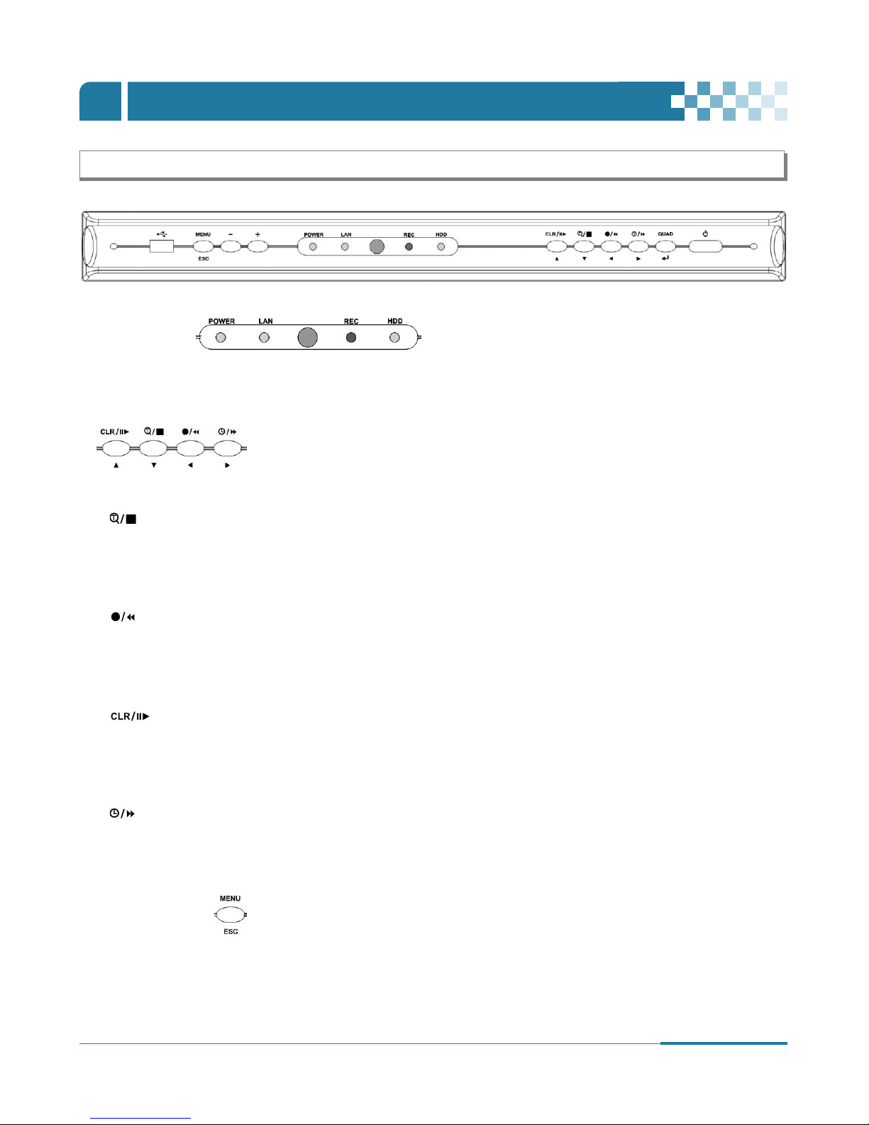
1. Front Panel
1. Mode Indicator :
4 LEDs display the status of the Digital Video Recorder. Power (Green), LAN (Green), HDD (Green) and Recording (RED)
2. Playback / Record control : These functions are used in Live Mode or Playback mode.
1) [Directional
…†œ √ ] buttons : In Menu setup mode, used to move the cursor.
2) [Time Search / Playback Stop]
!
Time Search : This button accesses the time search menu.
Use the directional buttons to select the date and the time. Press [Enter] button to start the playback of the selection.
@
Stop : This button stops playback
3) [REC / R step or FR]
!
REC : Press this button to start recording. Press the button again to stop.
@
Reverse Step : This button is used to move reverse field by field during STILL mode.
#
Fast Rewind : This button is used to fast rewind during PLAYBACK mode.
4) [Clear / Still or Playback] :
!
Clear : This button is used to hide the On-Screen-Display information such as the time, date and channel icons. This button
removes alert icons on the corner of the screen (AL, VL and PL). This button is also used to turn off the alarm buzzer.
@
Still or Playback: This button is used to still or 1 x playback during playback mode.
5) [Schedule / F step or FF] :
!
Schedule : Press this button to make scheduled recording standby. Press the button again to stop.
@
Forward step : This button is used to move forward field by field (picture by picture) during STILL mode
#
F.F. : This button is used to Fast Forwarding during PLAYBACK mode.
3. Menu / ESC Button :
1) Menu : Press this button to display the MAIN MENU screen.
2) ESC : Press this button to exit menu without saving.
8
DIGITAL VIDEO RECORDER
CONTROLS
Ⅰ
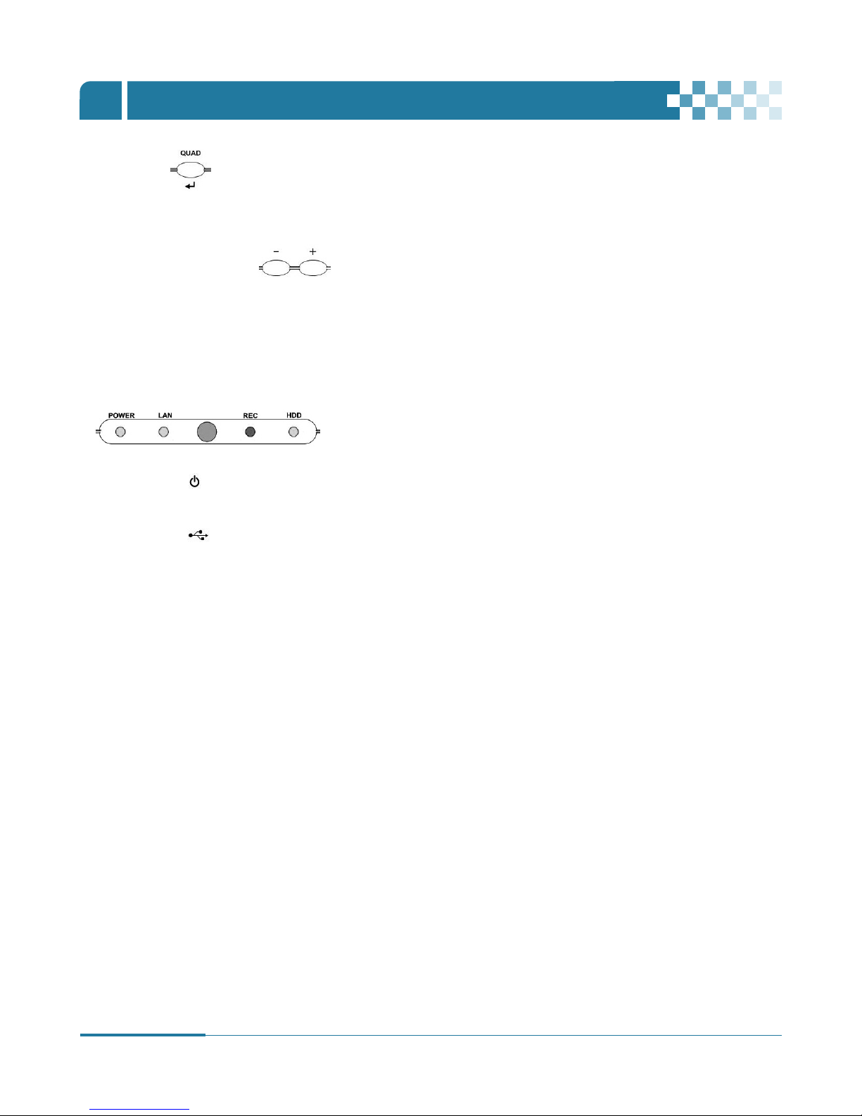
4. QUAD/Enter
1) QUAD : Press this button to display the cameras in multi-screen view.
2) ENTER : Press this button to save menu settings
5. Channel / Numeric Buttons :
Press the buttons to enter data or make selections. Press “–” or “+” to enter appropriate numbers
when prompted for a password, to choose channel/camera selection or appropriate dates in schedule option mode.
• [-, +] : To Decrease settings, To Increase settings
6. Remote control signal receiver :
Do not block the receiver port on the unit. Doing so may cause the remote controller to function improperly.
7. POWER button :
Press this button to turn the power on; press again to turn the power off. The POWER LED indicator is lit when the power is on.
8. USB connection : USB port allows light backups of video files to devices such as flash memory.
9
DIGITAL VIDEO RECORDER
CONTROLS
Ⅰ
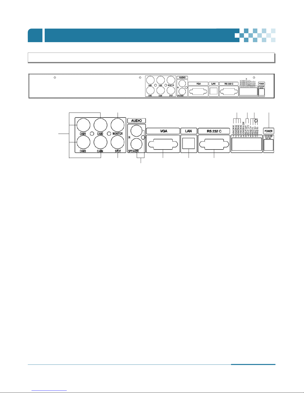
2. Rear Panel Connectors
1) CAM1~4 : BNC input (Camera 1~4) connectors
2) MONITOR (Composite Output) : BNC standard composite video output connector.
3) SPOT : Spot out connector
4) AUDIO Input / SPEAKER (Output) connectors : RCA
5) VGA out connector
6) LAN (RJ-45 Ethernet Port) : For connecting to remote PC via Ethernet network.
7) RS-232C [D-SUB 9PIN] : Development purposes only.
8) SENSOR (ALARM IN 1~4) : For connecting alarm inputs.
9) RELAY (ALARM OUT 1~2) : For connecting alarm out relays.
10) RS-422 : For connecting to PTZ camera.
11) POWER : DC power Jack
①
②
⑪⑧ ⑨ ⑩
③
⑤ ⑥ ⑦
④

10
DIGITAL VIDEO RECORDER
CONTROLS
Ⅰ
3. Remote Controller
TIME SEARCH
PTZ FOCUS OUT
BACK UP
PAN / TILT / ZOOM
FAST FORWARD
STEP
ESC / OSD OFF
MENU
+ BUTTON
CAMERA REPOSITIONING
DISPLAY MODE
ENTER
– BUTTON
INFORMATION
PTZ FOCUS IN
PLAY
REWIND
SCHEDULE REC ON / OFF
ZOOM
STOP
RECORD
Numeric &
Alphabetic
LOG
PTZ AUTO FOCUS
11
DIGITAL VIDEO RECORDER
INSTALLATION & CONNECTIONS
Ⅱ
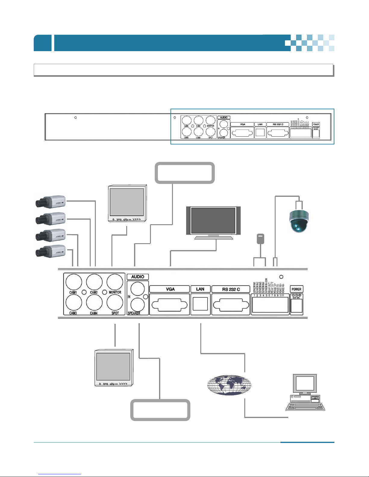
1. Camera, Monitor, Microphone, Alarm sensor and Power cord
1.1 System Configuration Diagram
The following illustration is showing the fully installed system.
CAMERA (BNC)
Main Monitor
Audio Input
(Microphone)
Audio Output
(Speaker)
INTERNET
COMPUTER
VGA Monitor
ALARM
PTZ CAMERA
Spot Monitor
12
DIGITAL VIDEO RECORDER
INSTALLATION & CONNECTIONS
Ⅱ
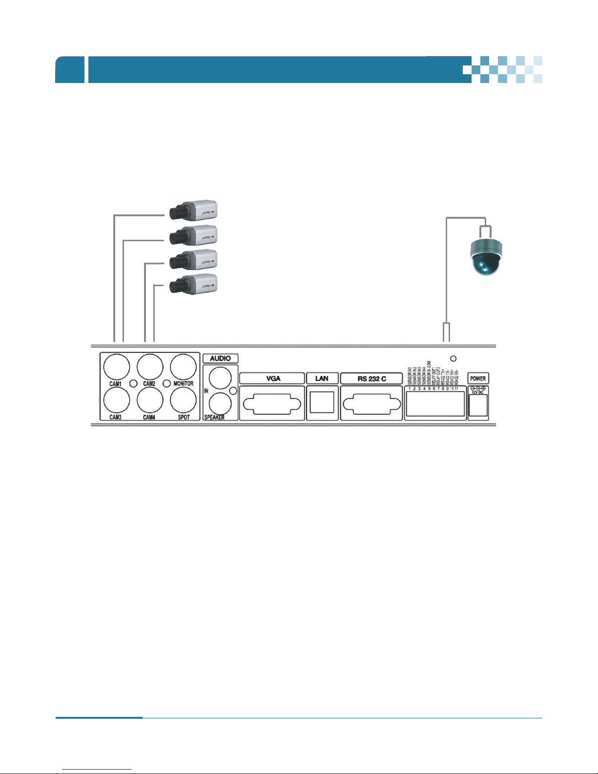
1.2 CAMERA
This product can be installed up to 4 cameras.
Connect cameras to the VIDEO IN (BNC) on the back panel of the system.
To connect a PTZ camera, connect the PTZ camera’s control line to the RS-422 TX+, RS-422 TX- terminal and connect the video
output to one out of VIDEO IN on the back panel of the product.
CAMERA (BNC)
PTZ CAMERA
13
DIGITAL VIDEO RECORDER
INSTALLATION & CONNECTIONS
Ⅱ
1.4 MONITOR
There are three video outputs (2-BNC, 1-VGA) on the rear panel of the system. Connect monitors depending on your application.
1- BNC for Main composite video output.
1- BNC for Spot composite video output.
1- VGA output.
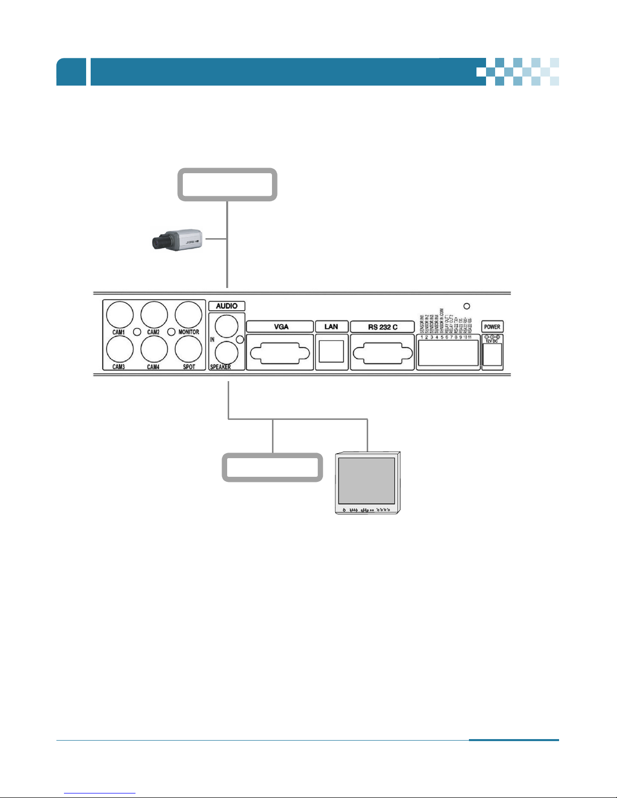
1.3 AUDIO
The system has one channel audio input and output. If you wish to record and playback audio signal, connect the proper audio
device (microphone) to the AUDIO IN (1 Vp-p @600 ohms) and speaker to the AUDIO OUTPUT (See illustration below).
Microphone
Speaker
MONITOR
CAMERA (BNC)

14
DIGITAL VIDEO RECORDER
INSTALLATION & CONNECTIONS
Ⅱ
2. PC system requirements for Network connection.
(a) Pentium-4 2.0GHz or higher
(b) 256MB System Memory
(c) 1,024 x 768 Display Resolution, 32 Bit color
(d) Windows XP, VISTA
(e) Spare 10/100-BaseT Ethernet Port
(f) RJ-45 Network Cable
(g) CAT-5 UTP Cable for LAN (Crossover cable for direct connect to PC)
(h) Microsoft DirectX 9.0c
It is recommended to have DirectX 9.0c version in Client PC. DirectX 9.0c is available for download from Microsoft homepage
(www.microsoft.com/windows/directx).
The remote viewing on network connection may not work on all personal computers due to difference
in personal settings and hardware configurations.
Disclaimer
15
DIGITAL VIDEO RECORDER
QUICK SETUP GUIDE
Ⅲ
■
To turn on the DVR, press [POWER] button on the front panel or on the remote controller.
1
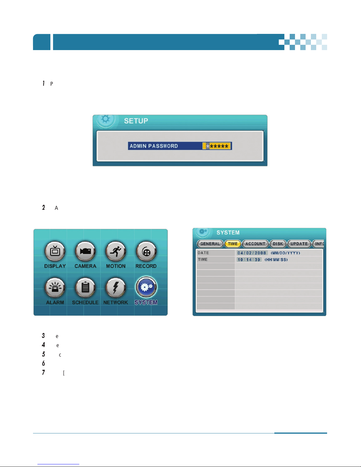
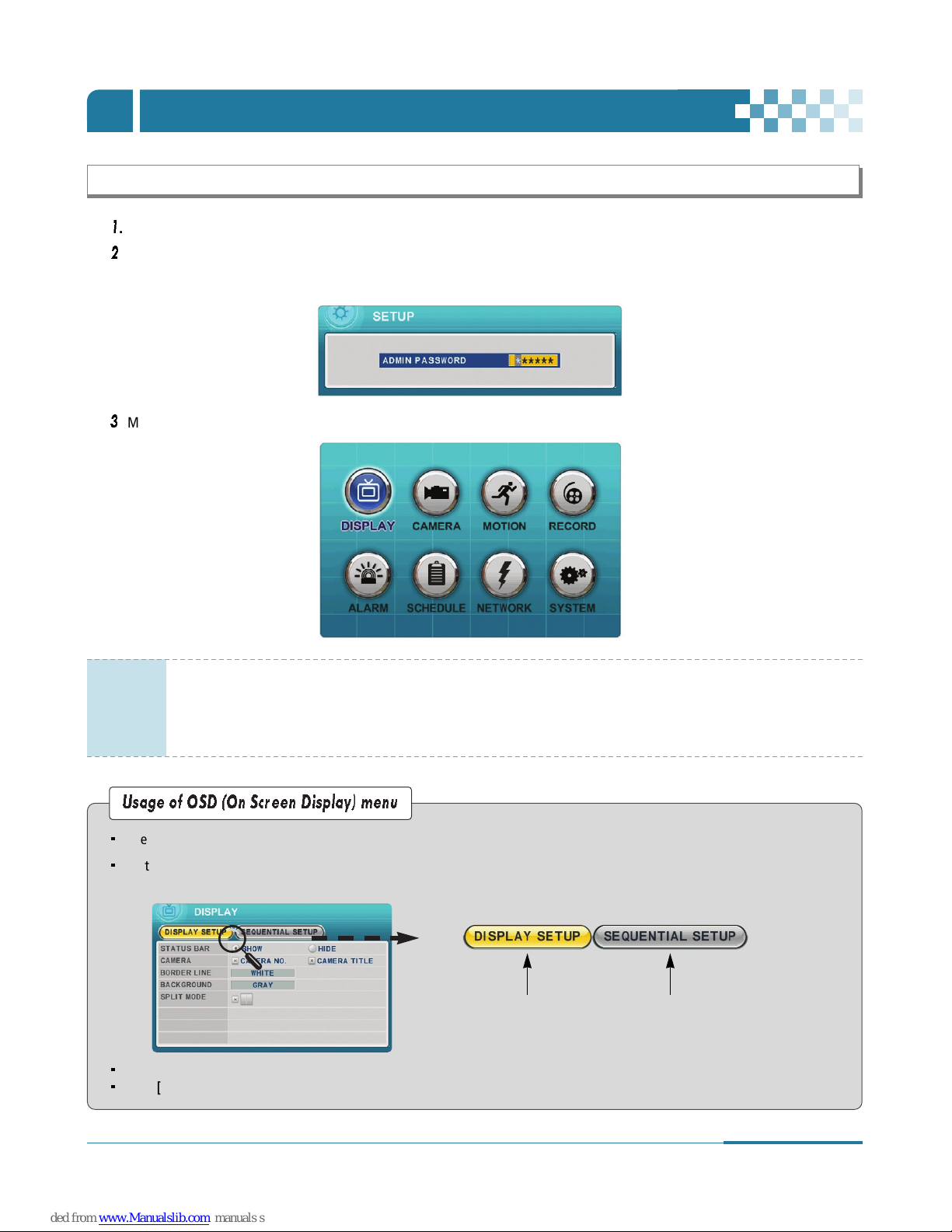
Press [MENU] button to display the MAIN SETUP screen.
Enter the password using Numeric buttons when prompted for a password.
2
MAIN SETUP menu appears once a password is entered.
The Factory Default password for the unit is “000000”(6 zeroes)
When the Digital Video Recorder is powered on for the very first time, the date and time are set as default to January 1, 2006 Sunday
01:00:00. Before commencing any operation of the Digital Video Recorder, it is important to set the date and time. Please refer to page
37 for setting the time and the date on the Digital Video Recorder.
3
Use Directional buttons
[…†œ √]
to select “SYSTEM” menu and press [ENTER] button to confirm.
4
Select “Time” on TAP menu by using Right [√] button.
5
Select the item by using Down [†] button.
6
Enter the Date and Time by pressing numeric buttons on the remote controller or “–/+” on the unit.
7
Press [ENTER] button to exit a menu with saving changes. Press [ESC] to exit a menu without making changes.
16
DIGITAL VIDEO RECORDER
LIVE VIEWING
Ⅳ
1. Display Overview
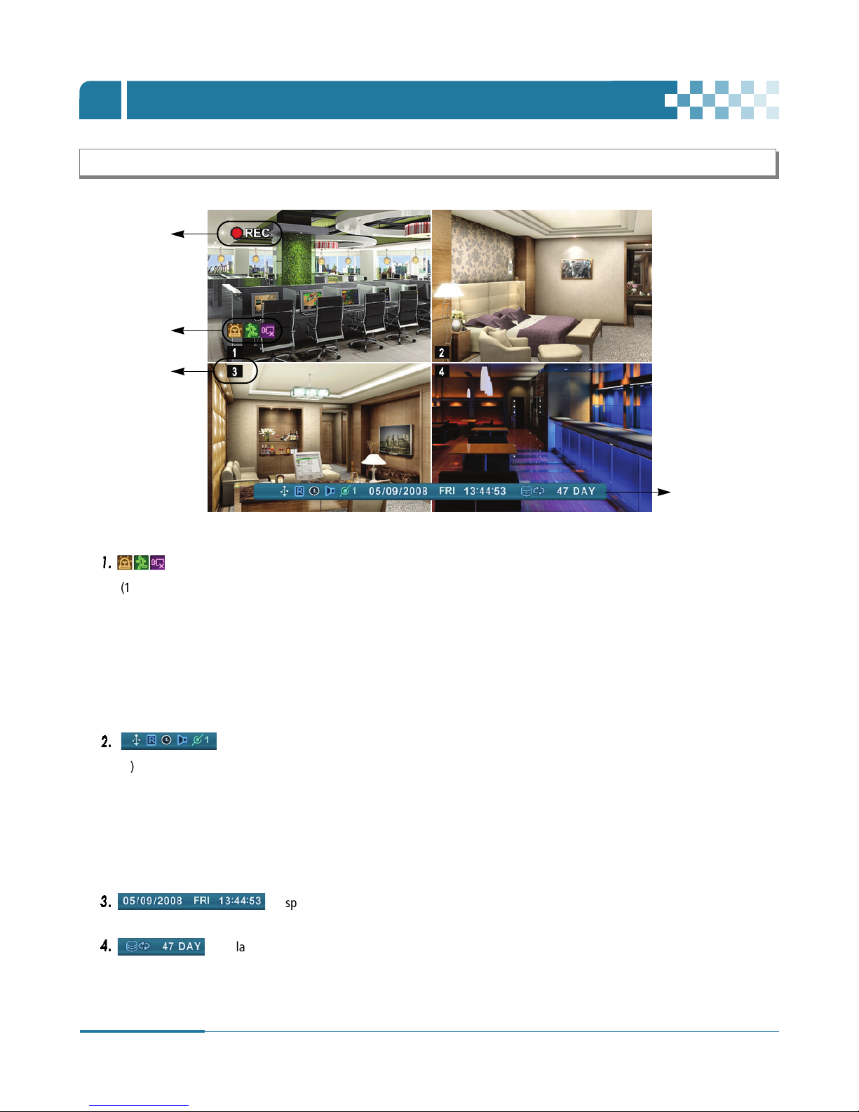
1.
(1) Alarm Icon is triggered by an alarm sensor. To remove the icon from the screen, press [ESC/OSD] button on the remote
controller or [CLR] button on the front panel.
(2) Motion Icon is triggered by a motion sensor. To remove the icon from the screen, press [ESC/OSD] button on the remote
controller or [CLR] on the front panel.
(3) Video Loss Icon indicates video loss incurred during recording. To remove the icon from the screen, press [ESC/OSD] button on
the remote controller or [CLR] on the front panel.
2.
(1) The indicator is on when a USB Device is connected The indicator glows in blue when the system is making light backups to
the USB device.
(2) The indicator is on when Record mode is on.
(3) The indicator is on when Schedule Record mode is on. The indicator light switches to blue when Schedule Record begins.
(4) The indicator is on during playback of recorded audio.
(5) The indicator shows the Number of Client, connected to Network (MAX:3).
3.
: Displays the Date (Day/Month/Year), Day of the week and Time.
4.
: Displays the remaining hard disk drive capacity available for recording.
“Recycling” icon glows in blue when the remaining hard disk drive capacity is running less than 4GB.
Recording Mode
Status
Event Indicator
(1) (2) (3)
(1) (2) (3) (4) (5)
Camera No
17
DIGITAL VIDEO RECORDER
LIVE VIEWING
Ⅳ
2. Multi-screen Display and Sequencing
2-1
. Full Screen Display.
Select any camera for Full Screen Display by pressing the Numeric button of the desired camera.
2-2
. Multi-screen Display and Sequencing Display.
• Press [DISPLAY] button on the remote controller or “QUAD” button on the front panel to activate the Multi-Screen Display.
• The sequence mode and dwell time are programmable. For more detailed information about the configuration, see “Sequence
Setup” on page 20. If the sequence mode is not activated, Quad mode will be automatically selected instead of Sequencing
mode.
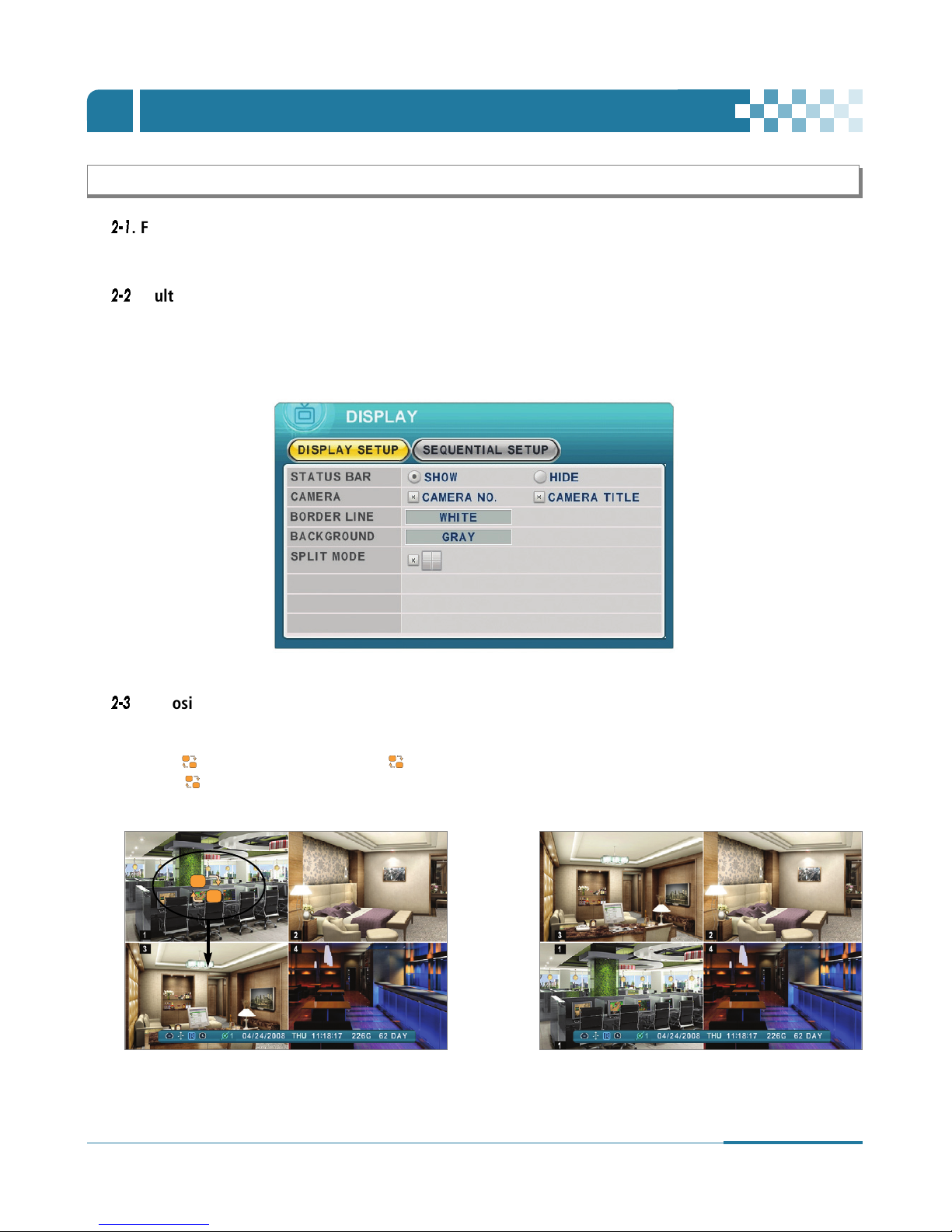
2-3
. Repositioning
To reposition a camera view on screen,
1) Press button on the remote controller. Icon will be displayed.
Move icon to the desired position with Directional […†œ √] buttons.
2) Press a Numeric button to reposition the selected camera.
3) Press [Enter] button to exit here with saving changes. Press [ESC] to exit without change.
Press [Menu] button to rearrange.
18
DIGITAL VIDEO RECORDER
LIVE VIEWING
Ⅳ
4. Spot Monitor
In addition to the Main Monitor, the Digital Video Recorder has a SPOT Monitor function.
The spot Monitor enables users to monitor specific channels independently from the main monitor.
1
. Press [Spot] button on the remote controller and press numeric button you wish view as full screen.
2
. Press [Spot] button twice to switch the cameras automatically. Sequence interval can be set from the Sequential Setup. (See
“Sequential Setup (Auto Sequence)” on page 21.)
*
When an alarm has been triggered, that specific channel will go into Full Screen.
The default mode is set to Auto Sequencing.
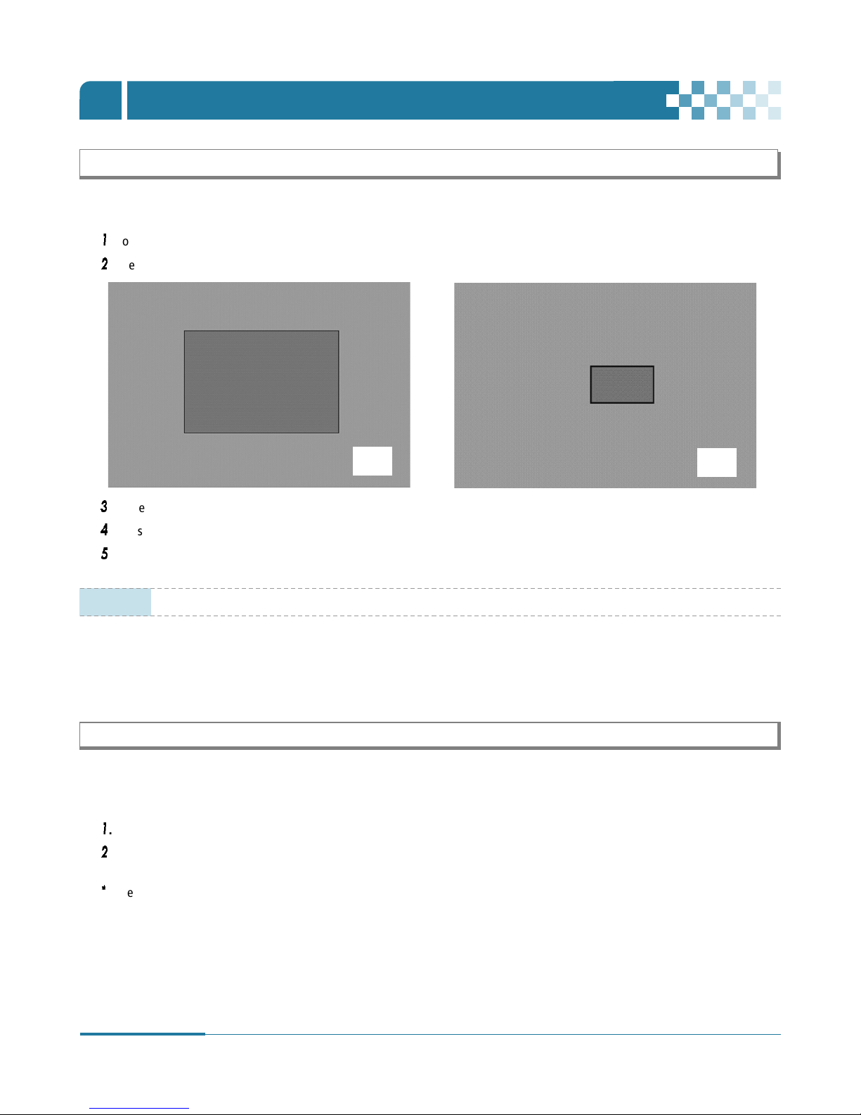
3. Zooming
During the live view mode or playback mode, it is possible to zoom a particular section of the screen to get a close-up view.
1
. To activate the digital zoom, select the full screen display of the camera you wish to zoom.
2
. Then press the [ZOOM] button on the Remote controller. Zoom area box pops up, as shown below.
3
. Move the box to the desired position using the Directional […†œ √] buttons.
4
. Press [+] button to zoom in, press [ - ] button to zoom out the image and then press the Enter button.
5
. Press [ESC] button to return to normal mode.
X 2
X 4
NOTE
If the Zoom button is pressed while in a multi-screen display, zoom operation is not activated.
19
DIGITAL VIDEO RECORDER
OPERATION
Ⅴ
1
. When the Digital Video Recorder is powered on, the Live Viewing screen will appear in about 30sec.
2
. Press [MENU] button on the remote controller or on the Front Panel to access the MAIN SETUP menu.
- An Admin Password Box will appear if the password is ON in the System Menu (Refer to section 9-1 General/Password).
- Enter the password using Numeric buttons on the remote controller or the CH increase button on the Front Panel
Default password is ‘000000’.
3
. MAIN SETUP menu appears after the [MENU] button is pressed or the proper password entered, as shown below.
1. MAIN Menu Overview
-
Select the desired menu by using Directional […†œ √] buttons. Items selected in the menu are shown in color.
-
Set the menu and display Sub-Menu by pressing [ENTER] button. Then select sub-menu on TAP menu by using Left / Right [œ √]
buttons.
Selected items will be highlighted in [Yellow] color.
-
Press [ENTER] button to exit menu with saving changes.
-
Press [ESC] button to exit menu without changes.
• Factory default Admin/user password is [000000]. It is recommended that users change the default “PASSWORD“.
See “9-3. Account“section of [System Setup] on page 37.
•
DVR will ask for a password when users access menu to setup, stop (schedule) recording, power off and using other
functions (playback, time search, backup and log). If you wish to bypass the procedure, change the selection of
password to “OFF“. Refer to 9-1 General on page 36.
NOTE
Selected Not selected
* Changes are automatically saved when moving
between TAP menu.
Usage of OSD (On Screen Display) menu
20
DIGITAL VIDEO RECORDER
OPERATION
Ⅴ
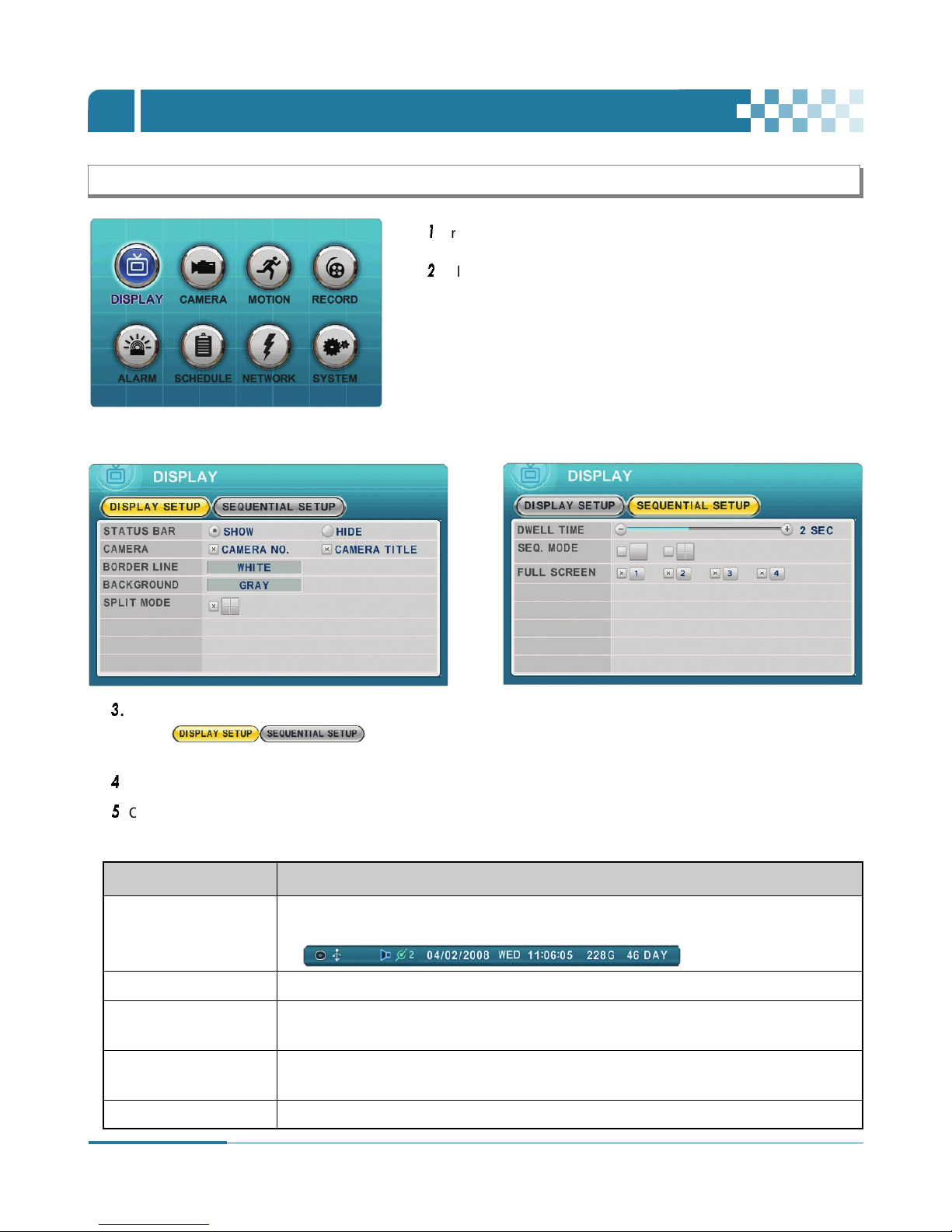
2. Display
2-1. Display Setup
3
. Press [ENTER] button to display “DISPLAY SETUP” or “SEQUENTIAL SETUP”.
Select ( ) on TAP menu
by using Left/Right [œ √] buttons.
Selected items will be highlighted in [yellow] color.
4
. Press Down [†] button to move down the menu.
5
. Change the values by using [-, +] buttons.
STATUS BAR •
Select “Show” or “Hide” by pressing [-,+] buttons. Choose “Show”, and below status bar will be
displayed on Main Monitor.
CAMERA • Select to view the On-Screen-Display information for Camera Number and Title.
BORDER LINE • Users can choose the color of border line by pressing [-,+] buttons.
[WHITE/GRAY/DARK GRAY/BLACK]
BACKGROUND • Select Background color on NO VIDEO status by using [-,+] buttons.
[GRAY/DARK GRAY/BLACK/BLUE/WHITE]
SPLIT MODE • Select to switch to the Quad Screen mode.
ITEM ADJUSTMENT
2-2. Sequential Setup (Auto Sequence)
1
. Press [MENU] button to access MAIN SETUP menu.
2
. Select DISPLAY by using Directional […†œ √] buttons.
[2-1. Display Setup]
21
DIGITAL VIDEO RECORDER
OPERATION
Ⅴ
6
.
Press [ENTER] button to exit menu with saving changes.
Press [ESC] to exit a menu without making changes.
3. Camera Setup
SEQ.INTERVAL 2 Sec • Specify the dwell time for each camera or Multi-screen mode is displayed.
(Dwell TIME) Users can set the desired sequential interval by using [-, +] buttons : 1 second ~ 5 second
SEQ. MODE None • Select the desired sequence mode.
FULL SCREEN ALL • Select the cameras to be included or excluded from the automatic sequencing.
ITEM DEFAULT ADJUSTMENT
[2-2. Sequential Setup (Auto Sequence)]
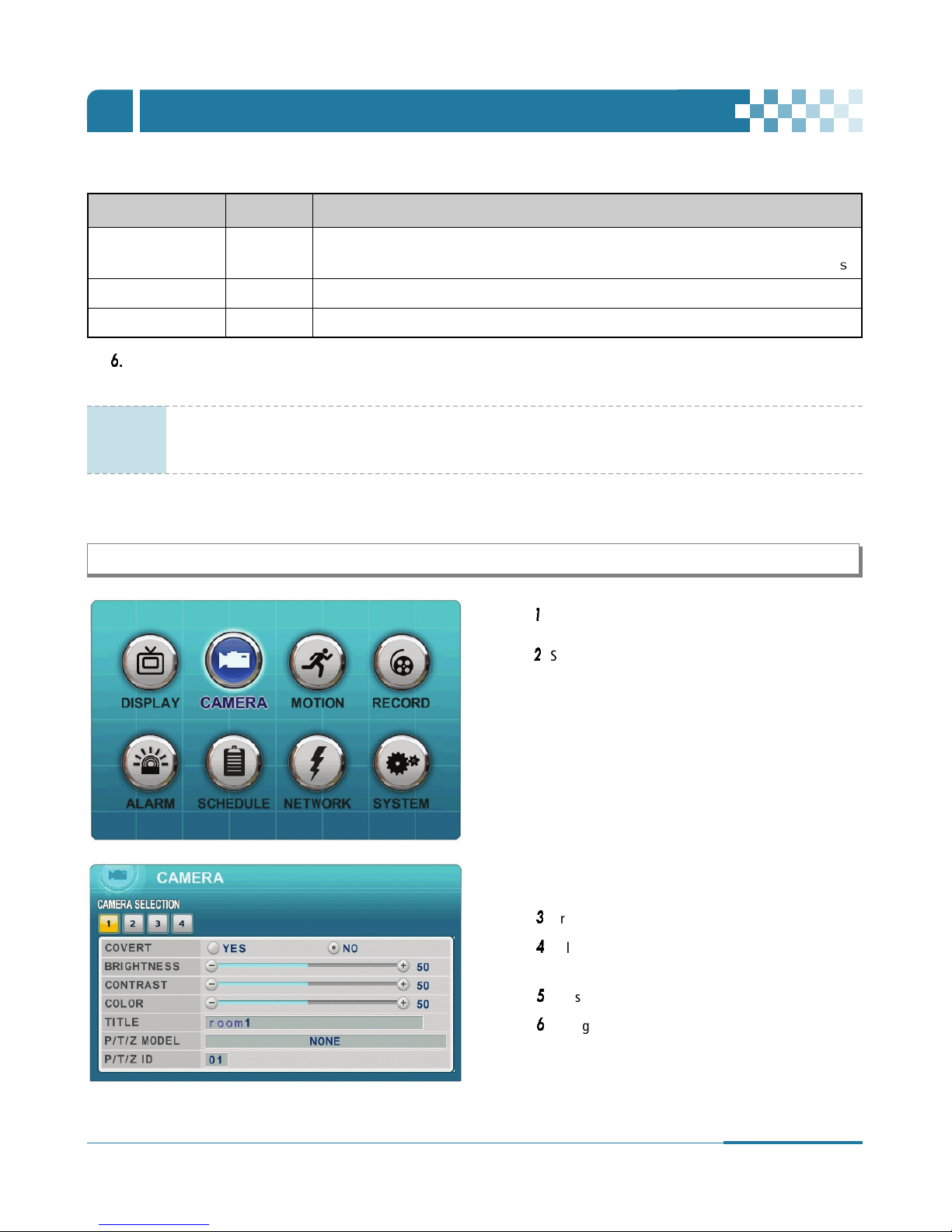
1
. Press [MENU] button to access the MAIN SETUP menu.
2
. Select the “CAMERA” menu by using Directional
[…†œ √] buttons.
3
. Press [ENTER] button to display the Camera menu.
4
. Select the Camera you wish to configure by using
Left/Right [œ √] buttons or Numeric buttons.
5
. Press Down [†] button to navigate the submenu.
6
. Change the values by using [-, +] buttons.
NOTE
- For automatic sequencing, press and hold [DISPLAY] button on the remote controller (or on the front panel)
for 2seconds after setting up the items above.
- To return to the Quad mode, press [DISPLAY] button.
22
DIGITAL VIDEO RECORDER
7
.
Press [ENTER] button to exit menu with saving changes.
Press [ESC] to exit menu without making changes.
< Insert characters from IR Remote Controller >
COVERT No • If the covert mode is set to “YES”, a selected camera will be invisible from
all live displays, playback and Network during recording.
Covert cameras are viewable after the covert mode is switched to “NO“.
BRIGHTNESS 50% • The brightness of each camera can be adjusted by pressing [-,+] buttons.
CONTRAST 50% • The contrast of each camera can be adjusted by pressing [-,+] buttons.
COLOR 50% • The color of each camera can be adjusted by pressing [-,+] buttons.
CAMERA TITLE Camera # • A name of camera titles can be composed of characters and figures.
Maximum 12 characters can be set.
By using the remote controller users can designate a title for each camera.(See below chart)
P/T/Z MODEL None • Select P/TZ camera model to control.
P/T/Z ID Camera No • Select an appropriate channel for the PTZ camera. Camera ID means Camera address.
No 1st Press 2nd Press 3rd Press No 1st Press 2nd Press 3rd Press
1A B 19Q R 9
2 C D 2 10/0 S T 10->0
3 E F 3 11 U V 11->
4G H 412W X
5I J 513Y Z
6K L 614. @
7M N 715– –
8 O P 8 16 SPACE
ITEM DEFAULT ADJUSTMENT
OPERATION
Ⅴ
23
DIGITAL VIDEO RECORDER
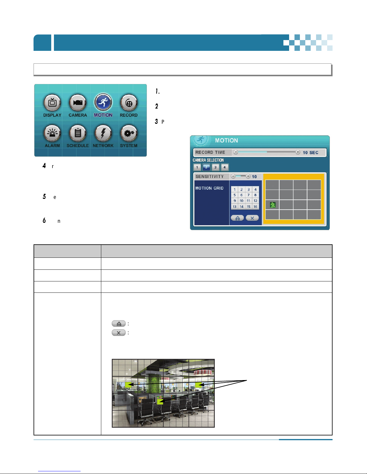
4. Motion Recording
1
. Press [MENU] button to access the MAIN SETUP menu.
2
. Select the “MOTION” menu by using Directional […†œ √] buttons.
3
. Press [ENTER] button to confirm.
RECORD TIME • Determines the duration of recording when motion is detected. [1sec to 20sec]
CAMERA SECTION • Select the Camera you wish to configure by using Left/Right buttons [ œ √ ] or Numeric buttons.
SENSITIVITY • Level 1 : Low sensitivity ~ Level 20 : High sensitivity. Select a Level by using [-, +] buttons.
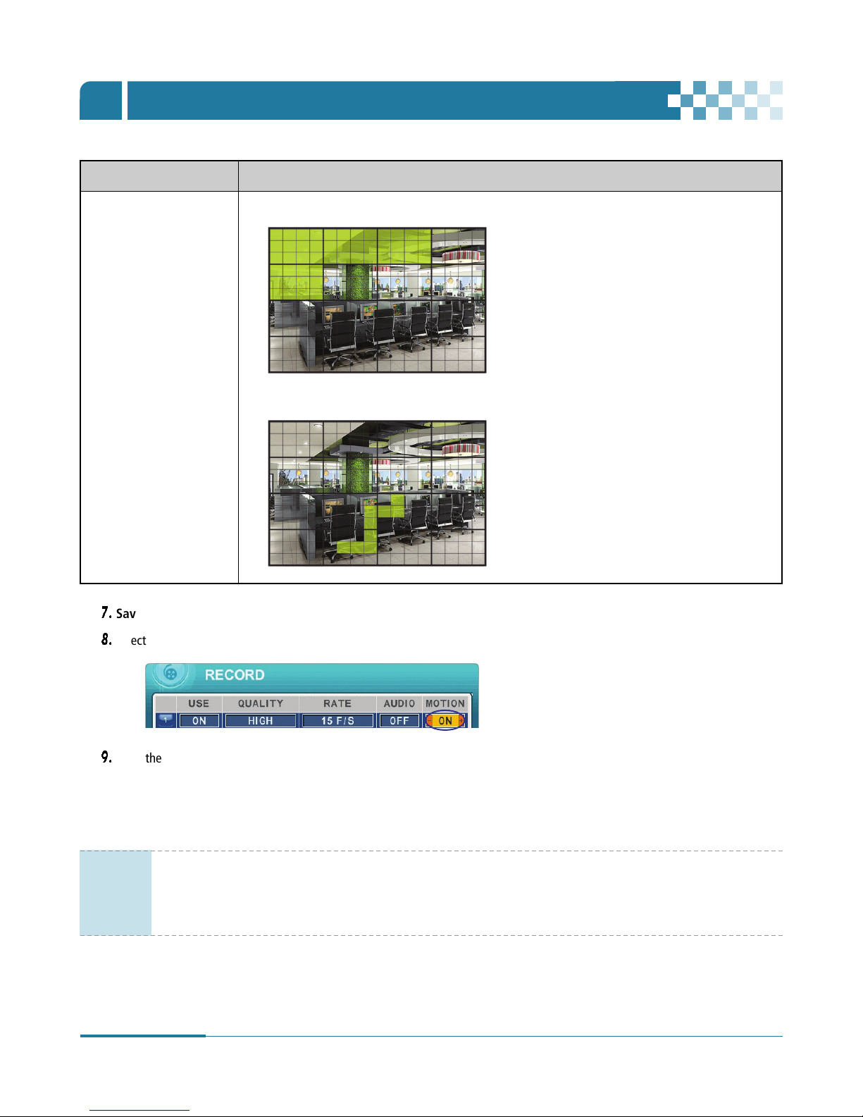
MOTION GRID • Use this menu to setup Zones for motion detection. The screen shown below will overlay
the current video image.
• Motion Grid is divided into 16 distinctive grids and selected by Numeric buttons on IR Remote.
• : Select All by pressing Enter button after selecting this icon.
• : Clear All by pressing Enter button after selecting this icon.
• The designated Motion zones display in blue and the Motion detected zones will be highlighted in
Green color. The factory default value is all set.
ITEM ADJUSTMENT
Motion Detected zones
4
. Press Down [†] button to move the camera selection
menu. Select a Camera you wish to configure by using
Left/Right [œ √] buttons or Numeric buttons.
5
. Press Down [†] button to navigate to the submenu and
use Left/Right [œ √] buttons to select other items.
6
. Change the values by using [-, +] buttons.
OPERATION
Ⅴ
24
DIGITAL VIDEO RECORDER
7.
Save changes and exit the menu. Press [ENTER] button to navigate “RECORD” Menu.
8.
Select “ON” or “OFF” to Enable or Disable motion detection per camera, as shown below.
9.
Press the REC button to begin recording. Motion recording begins according to the configured Recording Quality and Frame Rate
when Motion is detected. Stand-by mode will resume after motion recording time is finished. Recording does not commence under
normal conditions.
MOTION GRID • Designate a motion grid by using numeric buttons on the remote controller and press Enter button.
• Select smaller motion grids for more precise motion detection by using CMS.
ITEM ADJUSTMENT
NOTE
• Motion Duration will be extended if there is additional motion detection while motion recording.
• There may be cases when the recorder’s built-in motion detection function would not operate properly due to the
strength and quality of the input video signal and other factors.
• Users are recommended to select 3 or more motion blocks to get more accurate motion recording.
OPERATION
Ⅴ
25
DIGITAL VIDEO RECORDER
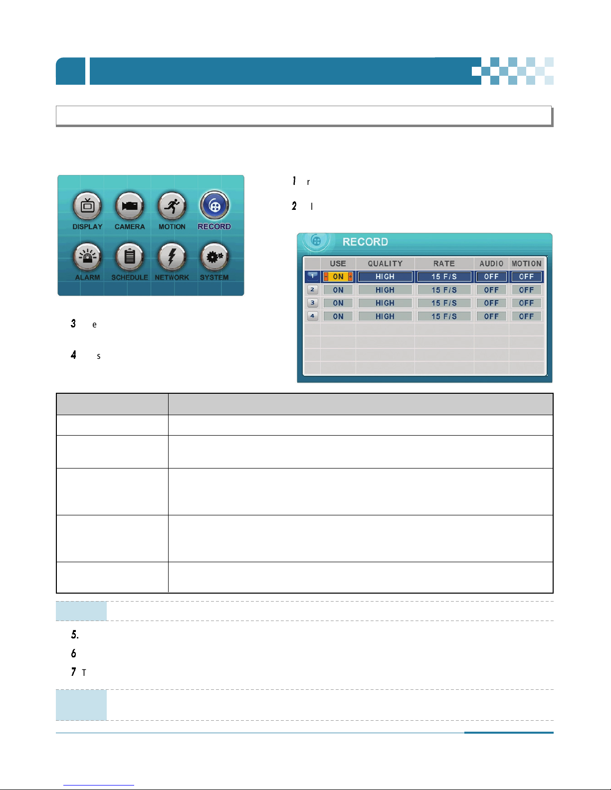
5. Continuous Recording
The DVR comes with a number of presets. Presets allow users to record without extensive setups. Therefore immediate recording is
possible by pressing the record button. By default, audio, alarm, motion recording are off.
5
.
Press [ENTER] button to exit menu with saving changes.
6
. Press [REC] button. Red REC LED on the front panel will come on to indicate that recording has begun.
7
. To stop recording, press ”STOP” on the remote controller or [REC] button again on the front panel.
USE • Enable (ON) or Disable (OFF) Recording for each camera.
QUALITY • Select recording quality for each camera.
[ULTRA/SUPER/HIGH/MIDDLE/LOW]
RATE • Select recording speed for each camera.
: Recording resolutions is changed to Frame, Field and CIF mode. (See “9-1. General” section of
[System Setup] on page 36.)
• Select audio recording: ON or OFF.
AUDIO Audio is always recorded in real time whereas video can be recorded in various
modes including real time. There may be a slight delay in synchronization between audio and video.
MOTION • Select Motion Recording ON or OFF. If ON is selected, cameras do not record under normal conditions.
It is discussed on Motion Recording Section. (Refer to page 23.)
ITEM ADJUSTMENT
NOTE
Estimated Recording Time varies due to different picture qualities and capture rates.
Estimated Recording Time is updated every 10 seconds.
NOTE
Press [MENU] button on each item at the first line to apply all settings for the rest of channels.
1
. Press [MENU] button to access the MAIN SETUP menu.
2
. Select the “RECORD” menu by using Directional […†œ √] buttons.
And press [ENTER] button to confirm.
3
. Select the Camera (1 to 4) you wish to configure by
using Directional […†œ √] buttons.
4
. Press [-, +] buttons to change the value.
OPERATION
Ⅴ
26
DIGITAL VIDEO RECORDER
6. Alarm Recording
Verify the alarm record settings prior to starting alarm recording. Please note that alarm recording is independent of any recording modes.
< Approximate File Size >
Quality
NTSC PAL
UNIT
720x480 720x240 360x240 720x576 720x288 360x288
LOW 6.5 4 2.5 8 4.8 3 KB
MIDDLE 9 5.5 3.5 10.8 6.6 4.2 KB
HIGH 13 8 5 15.6 9.6 6 KB
SUPER 19 12 7.5 22.8 14.4 9 KB
ULTRA 30 19 12 37 22.8 14.4 KB
* Actual file size may vary.
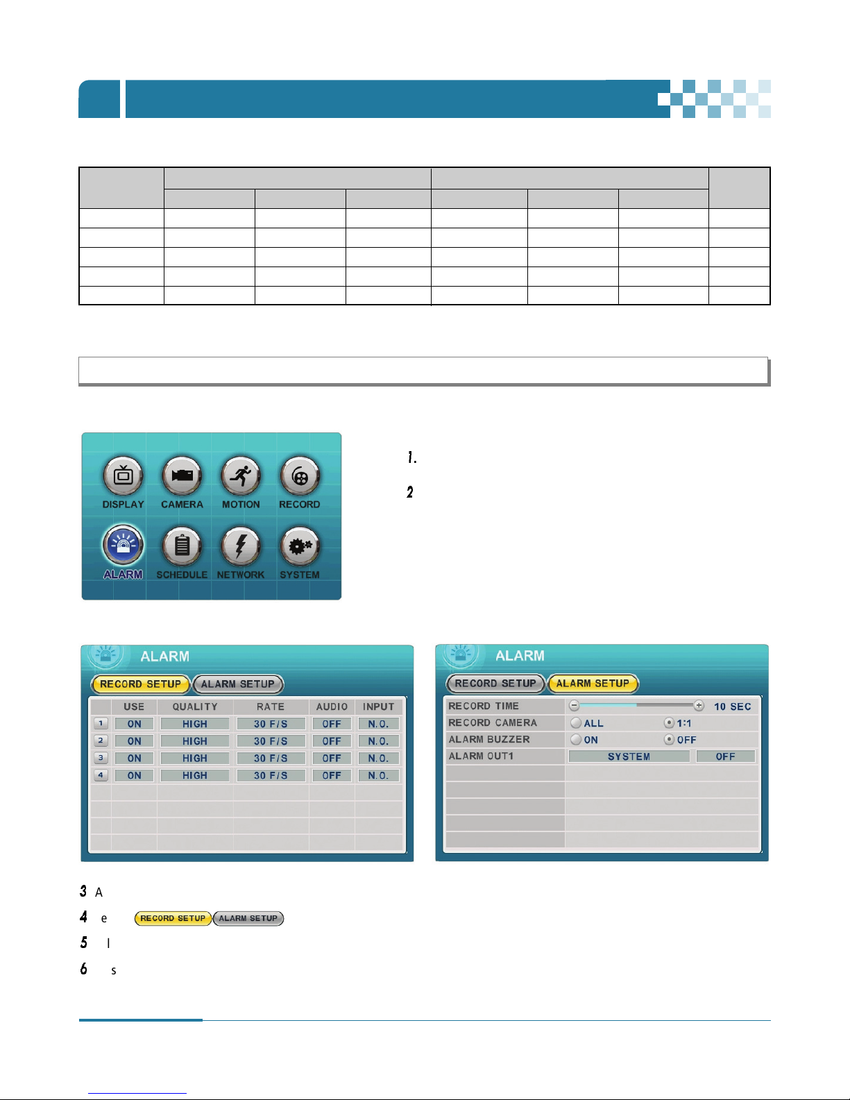
1
. Press [MENU] button to access the MAIN SETUP menu.
2
. Select the ”ALARM” menu by using Directional […†œ √] buttons.
3
. And press [ENTER] button to display “Record Setup”.
4
. Select ( ) on TAP menu by using Left/Right [œ √] buttons.
5
. Select the Camera you wish to configure, by using Directional […†œ √] buttons.
6
. Press [-, +] buttons to change the values.
6-1.Record Setup 6-2. Alarm Setup
OPERATION
Ⅴ

27
DIGITAL VIDEO RECORDER
USE • Enable (ON) or Disable (OFF) Alarm Recording for each camera.
QUALITY
• Select recording quality for each camera.
[ULTRA/SUPER/HIGH /MIDDLE/LOW]
RATE • Select recording frame rate for each camera.
AUDIO • Select audio recording : ON or OFF.
INPUT • Select input device.
For alarm recording, choose N.O. to connect N.O. (Normally Open) PIR Sensor.
ITEM ADJUSTMENT
7
.
Press [ENTER] button to exit menu with saving changes. Press [ESC] to exit menu without making changes.
8
. Press [REC] button after setting RECORD. Red LED light on the front panel will come on to indicate that recording has started.
RECORD TIME • Determines the duration of recording when an alarm is activated by PIR (Passive Infrared) sensor.
[1 to 20sec].
RECORD CAMERA • ALL : Records all alarm enabled channels if there any alarm is triggered.
• 1: 1 : Records a channel for which alarm has been triggered.
ALARM BUZZER • ON : Buzzer indicates whether alarm has been triggered.
Buzzer will remain on for the duration of record time. Set Alarm Out to “ON” for Alarm buzzer.
• OFF : Disables ALARM BUZZER function.
ALARM OUT1 • Configure which relay will be triggered when an alarm is activated per camera.
Choose one option among Video Loss, Motion, Alarm ALL, Each Alarm and System by using [-,+] buttons.
•
Press [Esc] button to stop Alarm Out. It will be cleared in the following order : Alarm > Motion > Video Loss.
ITEM ADJUSTMENT
NOTE
Press [-] button to stop alarm buzzer immediately.
Stopping alarm buzzer does not stop recording.
NOTE
If “System” is selected, the relay will be triggered when System has problems
such as HDD FAIL, FAN LOCK etc.
NOTE
Press [MENU] button on each item at the first line to apply all setting for the rest of channels.
[6-1. Record Setup]
[6-2. Alarm Setup]
OPERATION
Ⅴ

28
DIGITAL VIDEO RECORDER
<Example 1>
<Example 2>
Recording Priority
ALARM RECORDING STATUS
ON
• Resulting Actions:
Press the REC button to commence alarm recording based on the configuration shown above. (Recording Quality (Super), Frame
Rate (15F/S) and Audio). The system will revert back to stand by mode once alarm recording is finished.
The DVR system starts recording only when an alarm is activated.
RECORDING STATUS
USE MOTION
ON OFF
ALARM RECORDING STATUS
ON
• Resulting Actions:
Press the REC button to commence continuous recording based on the configuration shown above. (High picture quality at 3F/S
without Audio). If an alarm is triggered on this channel, the configuration will be changed to Super picture quality at 15F/S with
Audio. The system will revert back to continuous recording once alarm recording is finished.
Alarm Recording takes priority.
RECORDING STATUS
USE MOTION
OFF OFF
OPERATION
Ⅴ

29
DIGITAL VIDEO RECORDER
<Example 3>
RECORDING STATUS
USE MOTION
ON ON
ALARM RECORDING STATUS
ON
• Resulting Actions:
Press the REC button to commence motion recording based on the configuration shown above. (High picture quality at 3 F/S
without audio). If an alarm is triggered on this channel, the configuration will be changed to Super picture quality at 15F/S with
Audio. The system will revert back to stand-by mode for Alarm or Motion once alarm recording is finished.
The DVR system starts recording when an alarm is triggered or a Motion is activated.
NOTE
If two or more recording modes (Alarm, Motion or Continuous) are operational, the alarm recording mode takes
the highest priority followed by motion and continuous recording modes.
OPERATION
Ⅴ

7. Schedule Recording
30
DIGITAL VIDEO RECORDER
The schedule chart shown below provides four distinct modes (Mode 1 to 4).
6
. Enter the time for beginning and end by using numeric buttons and select Record mode to record.
(1) BEGIN : Set the start time by using numeric buttons.
(2) END : Set the end time by using numeric buttons. The ending time must not conflict with the start time.
(3) MODE : Up to 4 different recording modes can be preprogrammed. (MODE1 ~ MODE4)
1
. Press [MENU] button to access the MAIN SETUP menu.
2
. Select the ”SCHEDULE” menu by using Directional […†œ √] buttons.
Press [ENTER] button to display “Schedule Chart“.
3
. Select ( ) on TAP menu by using
Left/Right […†œ √] buttons.
4
. Select the day you wish to configure by using Down
button [†].
The week is composed of eight distinct categories :
ALL, SUN, MON, TUE, WED, THU, FRI and SAT. ALL
selects the entire week.
Daily schedule has priority over “ALL”.
5
. Press [Enter] button to configure the given day.
The submenu shown below will be displayed.
OPERATION
Ⅴ

31
DIGITAL VIDEO RECORDER
7
. Define modes below.
* Refer to Basic Recording for set up
8
. To activate the schedule recording, press the SCHEDULE button on the remote controller or on the front panel. The SCHEDULE
indicator will display on the status bar to indicate that the schedule recording has been activated. When a scheduled recording
begins, the REC indicator will display on the screen to indicate that the system has started recording.
9
. When a scheduled recording is finished, the REC indicator will go off to indicate that the system has finished recording.
10
. Press the SCHEDULE button to cancel a scheduled recording. The SCHEDULE indicator will go off to indicate that the schedule
recording has been cancelled.
NOTE
• The recording time is set by 24H (00:00 - 23:59). You need to set 2 days if the setting is over one day.
D/W BEGIN END MODE
Monday 18:00 23:59 MODE 1
Tuesday 00:00 08:59 MODE 1
• The recording will not start when the end time is ahead of the start time.
D/W BEGIN END MODE
Monday 18:00 08:59 MODE 1
< Summary of combination >
RECORD MODE MENU
RECORD ALARM SCHEDULE
CAMERA USE MOTION USE Normal MODE 1~4 CAMERA USE
Normal RECORD ON OFF OFF OFF OFF
Motion RECORD ON ON OFF OFF OFF
Alarm ALARM OFF OFF ON ON OFF
Schedule SCHEDULE OFF OFF OFF OFF ON
Schedule Motion SCHEDULE OFF ON OFF OFF ON
Normal and Alarm RECORD &ALARM ON OFF ON ON OFF
Motion and Alarm RECORD &ALARM ON ON ON ON OFF
Schedule and Alarm ALARM &SCHEDULE OFF OFF ON OFF ON
OPERATION
Ⅴ

8. Network Setup
32
DIGITAL VIDEO RECORDER
When the system uses the same IP address every time it connects to the network, it is known as a static IP address. If the system’s IP
address changes frequently, it is called a dynamic IP address. Check with your internet service provider to determine which IP address was
given. This manual will guide users through the set up process for both types.
• STATIC IP: Edit IP address, Gateway and Subnet Mask.
CONFIG
• DHCP: Dynamic Host Configuration Protocol automates the assignment of IP addresses, Subnet Mask,
Gateway and other IP parameters. The DHCP should be selected in order to utilize DDNS (Refer to section
8-3 DDNS for more information).
IP SETUP • Edit “IP ADDRESS, GATEWAY or SUBNET MASK” by using [-, +] or numeric buttons.
• Select “0000 ~ 9999” by using [-, +] or numeric buttons.
PORT The DVR’s connection port can be adjusted in case the default port 7000 is blocked. The DVR’s service port
may be adjusted to allow the connection from CMS.
ITEM ADJUSTMENT
1
. Press [MENU] button to access the MAIN SETUP menu.
2
. Select the ”NETWORK” menu by using Directional […†œ √]
buttons.
3
. And press [ENTER] button to display “IP Setup“.
4
. Press Down button [† ] to navigate.
5
. Press [-, +] button to enter appropriate information.
Press Directional […†œ √] buttons to navigate.
6
.
Press [ENTER] button to save changes and exit menu.
Press [ESC] to exit menu without making changes.
8-1. IP setup
OPERATION
Ⅴ
NOTE
Exceptionally, the IP SETUP Items won°Øt be changed by the Factory Default Setting in the System menu on page 36.

33
DIGITAL VIDEO RECORDER
NOTE
How to connect the DVR via Network to use DDNS
1. Select DHCP.
2. Check “Serial No” in System Menu.
3. Enter DNS name<e.g.: http://L50F9AB.dvrhost.com:7000>> in the address field of your web browser or CMS.
There are two ways to set up the notification email feature : “DEFAULT” or “Public/your own mail server”.
1
. Press [MENU] button to access the MAIN SETUP menu.
2
. Select the ”NETWORK” menu by using Directional […†œ √]
buttons. Press [ENTER] button to confirm.
3
.
Select “Email” on TAP menu by using Left/Right [œ √] buttons.
4
. Press Down button [† ] to navigate.
5
.
Press [-, +] or numerical buttons to enter appropriate information.
8-2. E-Mail
The DVR may notify users via email to alert an event to five different email addresses.
NOTE
The notification email message includes: alarm, video loss, power loss (when power is back on), HDD failure.
The notification email does not include motion detection.
OPERATION
Ⅴ
Router
DVR DVR
Dynamic IP

34
DIGITAL VIDEO RECORDER
OFF Select the e-mail notification feature on or off. The default is set to off.
USE
DEFAULT
Select Default email server: it is notified through manufacturer’s email server.
: Users need not setup SMTP server.
SMTP Select SMTP server: The notification would be performed by public email server. Setup the items below.
Server Select SMTP Server and then enter an email server’s domain name by pressing numeric buttons.
PORT Define the port that the SMTP server will communicate through.
SMTP
AUTH Select Authentication on or off. The default is set to off.
ID
Enter the user ID of Mail Server if your server needs Authentication.
(It is recognized as a small letter, even it’s displayed as a Capital Letter)
Password
Enter a password, if your server needs Authentication.
(It is recognized as a small letter, even it’s displayed as a Capital Letter)
E-mail Address Designate up to 5 email addresses for the notification feature.
ITEM ADJUSTMENT
8-3. DDNS
8-4. MISC
6
.
Press [ENTER] button to save changes and exit menu. Press [ESC] to exit a menu without making changes.
1
. Press [MENU] button to access the MAIN SETUP menu.
2
. Select the ”NETWORK” menu by using Directional […†œ √] buttons. Press [ENTER] button to confirm.
3
. Select “DDNS” or “MISC” on TAP menu by using Left/Right [œ √] buttons.
4
. Press Down button [† ] to navigate.
5
. Press [-, +] or numeric buttons to enter appropriate information.
6
. Press [ENTER] button to save changes and exit. Press [ESC] to exit menu without making changes.
OPERATION
Ⅴ

35
DIGITAL VIDEO RECORDER
[8-3. DDNS]
8-3.1. HOW TO SETUP AND USE THE DDNS
8-3.1.1. Router.
It has to be set as a virtual server (or port forwarding) in order to utilize the DDNS. There are a lot of manufacturers on the market.
Please read the provided manual thoroughly before setting or visit our website at www.cloverusa.com
in regards to do it.
We, the manufacturer of DVR systems will not support the solution to your individual network issues.
** DDNS (Dynamic Domain Name System) is a method of keeping a domain name linked to a changing IP address.
This is a useful feature since many computers do not use a static IP address.
8-3.1.2. Registration to the DDNS server
Visit at www.dyndns.org
to register.
Registration to DYNDNS.ORG
1. Visit at www.dyndns.com
.
2. Sign up for a new user name and a password: Click the Create Account on the upper right hand corner.
3. After signup new user, check your e-mail and confirm an e-mail from dyndns.com.
4. Go back to www.dyndns.com
and log in with the ID and the Password.
5. After log in on dyndns.com front page, click on my services.
6. Click on the Add Host Service (Next to Host Level Service).
7. Click the Add Dynamic DNS Host on the Dynamic DNS.
8. The window to input Host Name will pop up, and select the dyndns.org or the dvrdns.org on the pop-up window.
9. To complete, click the Add Host button on the bottom.
10. After registration, go to the DDNS menu on the DVR and enter the HOST NAME, USER ID and the PASSWORD you just registered.
• OFF : NO use of DDNS
• DEFAULT : “Dvrhost.com” is set as the default domain name.
USE If the system’s host name in the SYSTEM menu/INFO is set to L50F9AB, the corresponding
DDNS address will be : http://L50F9AB.dvrhost.com:portNO.
• DYNDNS : “Dyndns.com” is set as the domain.
Domain Name • Enter your domain name if you use “Dyndns” or your own Domain.
User ID • Enter user ID for DDNS.
Password • Enter user PW for DDNS
Update • Test your DDNS address.
ITEM ADJUSTMENT
ITEM ADJUSTMENT
[8-4. MISC]
BANDWIDTH • The default is set to unlimited. Select between “64 KBPS~ 8MBPS” to optimize your network performance.
OPERATION
Ⅴ

36
DIGITAL VIDEO RECORDER
ITEM ADJUSTMENT
9. System Setup
3
. Select the items by using Down button [].
4
. Press [-, +] buttons to enter appropriate information.
AUTO LOCK
• All buttons will be locked after three minutes of inactivity. The buttons can be unlocked by entering a
password. The auto lock feature is by default set to “OFF”.
KEY TONE
• By default, the DVR emits a beep every time a button is pressed. Set the key tone to off when you wish to
turn off beep. The Default is set to “ON”.
• CIF : The system records each camera individually and then multiplexes them. Each channel records at
Field resolution: 360x240(360x288).
RECORD SIZE • Field : The system records each camera individually and then multiplexes them. Each channel records at
Field resolution: 720x240(720x288).
• Frame : 720x480(720x576)
PB DEINTERLACE
• ON : Reducing image flickering but less picture quality.
• OFF : Better picture quality for still image but image flickering for moving picture.
•
If the system is interrupted or shut down during recording, the system will preserve the previous recording
setting and resume the recording after a reboot.
• If “ON”, the system will ask for a password when users access menu to setup, stop (schedule) recording,
turn off the system and using other functions (playback, time search, backup and log).
• If you wish to bypass the procedure, change the selection of password to “OFF”.
FACTORY DEFAULT • To restore factory default settings, stop recording and then execute “START” by using ENTER button.
PASSWORD
RUN ON BOOT
1
. Press [MENU] button to access the MAIN SETUP menu.
2
. Select “SYSTEM” menu, by using Directional […†œ √] buttons.
Press [ENTER] button to confirm.
9-1. General
5
.
Press [ENTER] button to save changes and exit menu. Press [ESC] to exit menu without making changes.
NOTE
The following items should be performed in the live mode only.
- Factory default setting. - Setup time and date.
- Updating a firmware. - Formatting a HDD.
OPERATION
Ⅴ
37
DIGITAL VIDEO RECORDER
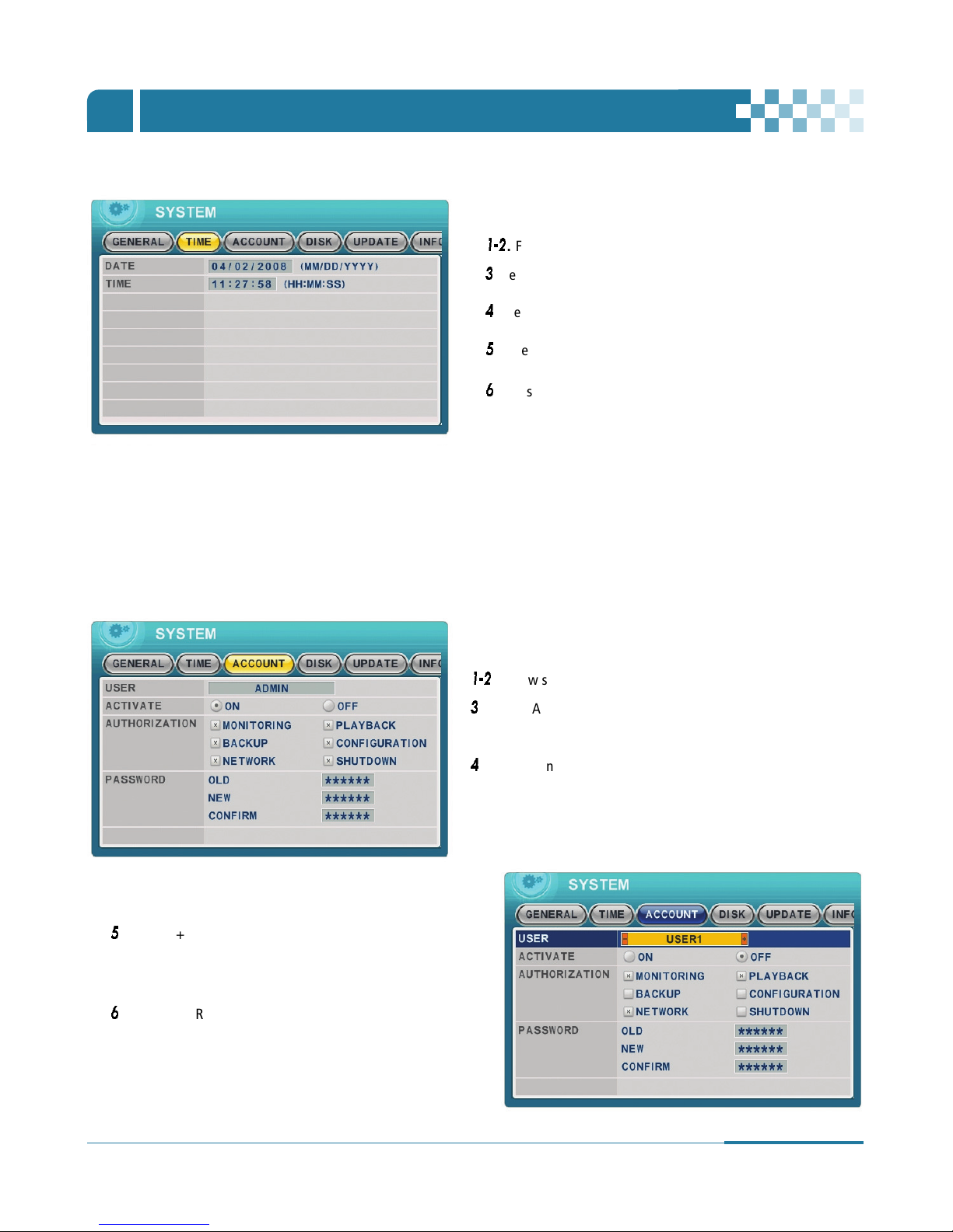
9-2. Time
9-3. Account
1-2
. Follow steps 1-2 as shown under “9-1. General” on page 36.
3
. Select “TIME” on TAP menu by using Right [√] button.
4
. Press Down button [† ] to navigate.
5
.
Enter the Date and Time by using numeric buttons.
6
.
Press [ENTER] button to save changes and exit menu.
Press [ESC] to exit menu without making changes.
- A user with administrator privileges may define each user’s authority. Select appropriate user level from User 1~5 in the user box
shown below. By setting the activate option on, administrator may control individual settings for each user: Monitoring, Playback,
Back up, Network, Configuration (Main Menu Setup), Shutdown (Power off).
- Enter the 6-digit number for a new password, and re-enter the same password in the CONFIRM section.
1-2
. Follow steps 1-2 as shown under “9-1. General” on page 36.
3
. Select “ACCOUNT” on TAP menu by using Left/ Right [œ √]
buttons.
4
. Press Down button [† ] to navigate.
5
. Press [-, +] or numeric buttons to enter appropriate
information.
6
.
Press [ENTER] button to save changes and exit menu.
Press [ESC] to exit menu without making changes.
OPERATION
Ⅴ

38
DIGITAL VIDEO RECORDER
OPERATION
Ⅴ
9-4. DISK
! Stop recording, playback, backup and searching before commencing disk formatting.
@ Select a device by using [-, +] buttons. ( Internal HDD or USB (Front) Memory Stick )
# Select “START” by using down button [†], and press [ENTER] button to start formatting.
$ Formatting will begin, and the progress will be displayed in the status line.
Please note that it takes approximately 10~30 seconds to format a HDD.
% When formatting is finished, it will display COMPLETE, and SUCCESS in the status line.
Users may select the record policy of the system’s internal hard disk drive. By default, the system’s hard
disk drive is set to overwrite from the beginning when it becomes full.
• ON: Overwrite your HDD from the oldest file when the HDD is full.
• OFF: Stop recording after your HDD is full.
• It stops automatically if HDD failure happens. It starts to “Monitoring” again after DVR reboot .
(Press the Enter button to select the Stop or Start and then press the ESC button.)
ITEM ADJUSTMENT
9-5. UPDATE
4
. Press Down button [†] to navigate.
5
. Press [-, +] buttons to enter appropriate information.
6
.
Press [ENTER] button to save changes and exit menu.
Press [ESC] to exit menu without making changes.
1
. Press [MENU] button to access the MAIN SETUP menu.
2
. Select “SYSTEM” menu, by using Directional […†œ √] buttons.
Press [ENTER] button to confirm.
3
. Select “DISK” on TAP menu by using Left/ Right [œ √] buttons.
FORMAT
OVERWRITE
DISK MONITOR
1-2
. Follow steps 1-2 as shown under “9-4. DISK” on page 38.
3
. Select “UPDATE” on TAP menu by using Left/ Right [œ √] buttons.
4
. Press Down button [† ] to navigate.
5
. Download the latest firmware file and copy to USB Flash memory
stick in the Root Folder.
6
. Turn on your DVR.

39
DIGITAL VIDEO RECORDER
9-6. INFO
Press INFO button on the remote controller to view the system information
as shown below.
MODEL • Display Channel Number and compression.
HOSTNAME. • Display hostname and Mac Address.
LANGUAGE • Display the language of the system.
NETWORK • Shows the current IP and Port of the system.
INTERNAL HDD • Displays numbers of HDD and total HDD size .
USB (FRONT) • Displays what kind of device is connected to the front USB connector.
• Shows the Primary HDD status. A : Master, C: N/A
<
note>
IDE BUS 0 ** “ERROR” means the HDD damaged physically.
Indicator CONDITION
H/w VERSION • Shows the Main PCB version of the system.
S/W VERSION • Shows the Software version of the system.
Indicator CONDITION
7
. Plug USB memory stick into the front USB port and check if USB icon shows up on the Status bar.
8
. Select START by using down button and pressing [ENTER] button.
9
. Wait for the system to finish the update. Once finished and “Reboot” and “Success” messages are displayed,
press [ENTER] button to restart your DVR.
1-2
. Follow steps 1-2 as shown under “9-4. DISK” on page 38.
3
. Select “INFO” on TAP menu by using Left/ Right [œ √] buttons.
OR
It will be displayed when the HDD support S.M.A.R.T function. Please change this HDD to NEW HDD in
the case of “WARNING”.
OPERATION
Ⅴ
NOTE
• Please make sure your USB Flash memory stick has enough storage space for 10MB.
• Do not make a special folder into memory stick for these files.
• Do not format the USB at window, just remove all files inside.
• Do not power OFF or PRESS any key during the update process.

40
DIGITAL VIDEO RECORDER
PAN / TILT ZOOM CONTROL
Ⅵ
1. P.T.Z. Menu
1
. To activate the Pan/Tilt Control, select the full screen display of the camera you wish to control. Switch to Full screen display by
using numeric buttons
2
. And press the [P/T/Z/FOCUS] button. Short-cut Menu box pops up, as shown below.
3
. Then press [ENTER], [ESC], [MENU], […†œ √] or [-, +] button.
NOTE
Please Refer to Help Menu for specific control.
• Press this button to display “HELP“ Menu. Press [ENTER] Button again, or [ESC] button to cancel
Help Menu.
• Press this button to cancel “PAN/TIT“ Operation.
• PTZ camera control interface will be extended to use whole
function. Press this button again to view short-cut menu.
INDICATOR RESULTING ACTIONS
[ENTER] Button
[ESC] Button
[MENU] Button
• Use up and down directional buttons to tilt.
• Use left and right directional buttons to pan.
• Press + and - to zoom in and out.

41
DIGITAL VIDEO RECORDER
PAN / TILT ZOOM CONTROL
Ⅵ
2. Preset & Tour
• Set preset position; SPOT OUT on the remote controller
- Move the PTZ to a desired location.
- Press the Preset button.
- Custom 1 will illuminate.
- Set the # for the Preset location.
- Press Enter to save and exit.
• Go to preset position; INFO on the remote controller
- Press the Go button.
- Enter the desired Preset # and press Enter.
• Start Auto Tour; BACKUP on the remote controller
- Press Auto Tour Button.
- Press the + button and enter the range of Preset and press Enter.
- For Example, Auto Tour Button, +5 will start the tour of 1 ~ 5 presets of the PTZ Camera
Button Function
The layout of the PTZ interface conforms to the layout of the front of the DVR or the remote controller. Menu button is the guide anchor
position for all other buttons. When in PTZ interface mode, all buttons used for the PTZ related operation.
** Please Check the followings before using PTZ Camera.
1
. RS 232/485 Connection, camera Jumper Setting and etc
2
. Set the PTZ Camera ID & MODEL NO in the Display menu.
3. Custom Functions
PTZ custom function 1; DISPLAY on the remote controller
PTZ custom function 2; ZOOM on the remote controller
PTZ custom function 3; P/T/Z on the remote controller
Button Function
Please refer to manufacture’s instruction manual for proper jumper settings to match the protocols for the DVR.

42
DIGITAL VIDEO RECORDER
PAN / TILT ZOOM CONTROL
Ⅵ
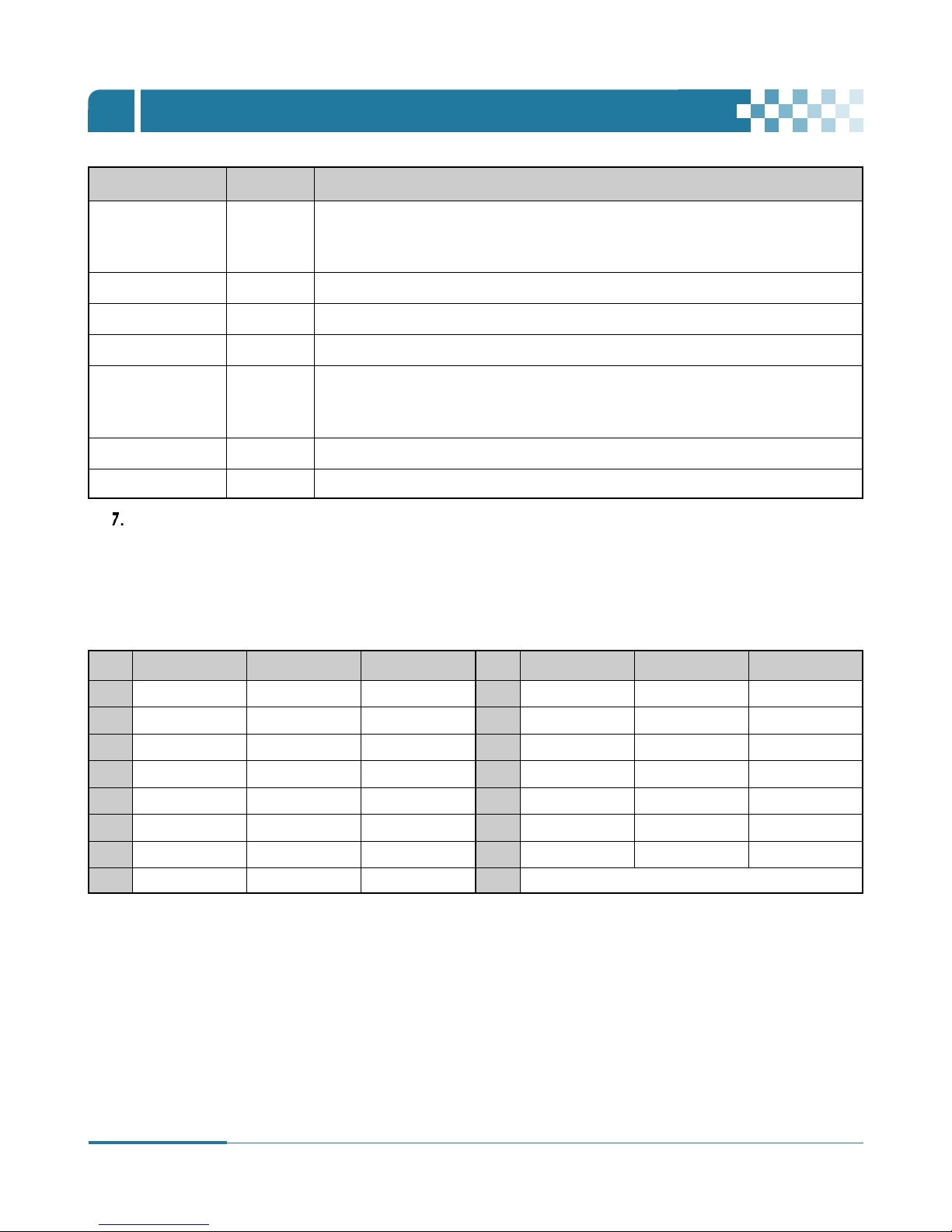
4. PTZ Camera Model - PAN/TILT/ZOOM Camera List
# Model Name 3X Speed Preset Go to Tour A. Pan A.Tilt Pat Me
Esc/
Enter
1 NUVICO, NV 9600 BPS o o o o o o o o
2 MERIT LILIN, PIH-7000/7600 o o o o o o o o
3 VCL, Orbiter Microsphere o o o o
4 SAMSUNG, SCC-641 o o o o o o o
5 NEC, NC-21D o o o o
6 SUNKWANG, SK2107 o o o o o
7 RESERVED o o o o o
8 D-MAX, PTZ PROTOCOL o o o o o o
9 LG, LPT-A100L P/T/Z o
10 HONEYWELL, GCC-655N
11 WONWOO, PT-101 o
12~14 PELCO, D 2400~9600 o o o o o o o o
15 C&B TECH, AN200 o o o
16 CANON, VC-C4 o o o
17~19 PELCO, P 2400~9600 o o o o o o o o
20~22 PELCO, EP 2400~9600 o o o o
23
PANASONIC, WV-CS/W85x, 86x
oo oo oo
24 HONEYWELL, HSDN-251N/P o o o o
25 GE/KALATEL, CyberDome o o o o o
26 DY ELEC, SmartDome o o o o o
27 BOSCH, TC8560/TC700 o o o o
28 SYSMANIA, ORX1000
29 AD, DELTADOME o o o o o
30 HUNT, HTZ-2300 o o o o o o
31 HAZEM, RESERVED o o o o
32 RVT, EZ Protocol o o o o o o o o
33 LG, MULTIX o o o o o
34 ELMO, PTC-200C/400C o o o o
35 NICECAM, MP-1xxx o o o o
36 C&B TECH, CNB-PTZ102 o o o o o
NOTE
Speed has 0~8 steps
1 (Slow) – 8 (Fast)
* 0 – Keep pressing the button to increase speed.

43
DIGITAL VIDEO RECORDER
SEARCH / PLAYBACK
Ⅶ
1.Time Search
1
. To start playback, press [Time Search] button to display the time search menu on the remote controller,as shown below.
2
. Use Left /Right [œ √] button to choose a month in the box.
3
. Use directional […†] buttons to select a day on the calendar. Graphical bars will be displayed to indicate video recordings stored
on the system. Then press [ENTER] button.
4
. Select “Hour and Minute” or “the camera” you wish to playback by using directional [-, +] buttons.
5
. Press [ENTER] button to start playback.
NOTE
• Users will not be able to choose a month if there is no stored data (i.e. past recording).
• The data are colored based on different category : Alarm(Red) > Motion(Green) > Continuous(Yellow).
NOTE
• To display the multi-screen, press [ENTER] button after selecting “Hour and Minute”.
•
To display a full screen, press [ENTER] button after selecting “Hour, Minute and one out of 4 camera channels”.
NOTE
In case of playing recorded data along with audio data, the corresponding channel should be in full screen.

44
DIGITAL VIDEO RECORDER
SEARCH / PLAYBACK
Ⅶ
2. Log List Search/Alarm, Motion Search
The logs can be used to directly search and review a particular event in the recorded data. Alarm, motion, video loss and system related
logs can be searched and played directly from the time of the incident.
1
. To start Event Search, press [Log] button on the remote controller to view the log List menu, as shown below.
2
. Select “Time“ to play by using Up/Down […†] buttons. Proceed to next page by using Left/Right [œ √] buttons.
3
. Press [ENTER] button to start playback.
ALL Lists all events since the initial operation of the system.
SYSTEM Lists all events except for Alarm, Motion, and Video Loss.
ALARM Displays alarm list.
MOTION Displays motion list.
VIDEO LOSS Displays video loss list.
MENU TAP CONDITION
NOTE
• Log list is saved on the system’s HDD.
• To copy a log, connect USB memory stick into USB port on the front.
Then press Menu button for each category to backup the log.

45
DIGITAL VIDEO RECORDER
BACKUP
Ⅷ
1. USB Memory Stick Backup
< Recommended USB memory stick for backup >
no. Brand Capacity
1 HP 1G
2 2G
3 256M
4 LG X-XTIC 1G
5 2G
6 4G
7 BUFFALD Clip Drive 512M
8 512M
9 Sandisk Cruzer 1G
10 2GB
11 512M
12 Kingston 1G
13 2G
14 128MB
15 MEMORIVE 256MB
16 1GB
17 2GB

46
DIGITAL VIDEO RECORDER
BACKUP
Ⅷ
1
. Insert a USB Memory Stick into the USB connection port on the front panel.
2
. Press [BACKUP] button on the remote controller to display the backup menu.
3
. Use [-, +] button to select the device: USB (Front) Memory Stick
4
. Select the data for BACKUP.
(1) CONTINUOUS: Continuous Recording Data
(2) ALARM: Alarm Recording Data
(3) MOTION: Motion Recording Data
The illustration to the left has selected ALL CAMERA, CONTINUOUS, ALARM and MOTION data.
5
. Enter the numbers as required in 24-hour format, then move to .
6
. Press [ENTER] button to start BACKUP.
* USB icon will be highlighted in blue during the backup.
• If there is not enough space on your USB memory stick, the system will not proceed with backup.
USB Memory Stick
NOTE
Make sure your USB device has enough space before commencing backups.
The backup progress indicator will be displayed at the bottom of the window. While the system is in backup session,
please do not perform playback.
7
. After backup process is finished, USB icon will be highlighted in white.
NOTE
Refer to [LOCAL PLAYER] section to read Back-up Device.

47
DIGITAL VIDEO RECORDER
Ⅰ
BACKUP
Ⅷ
1
. With “Mcdplayer”
- Plug a USB memory stick into your PC (no software installation is required).
- Double-click on “Mcdplayer” in the window as shown above and will play as follows.
2
. Backup data can also be played by “CLViewer”.
Please refer to the page 78 in the “CLViewer” manual.
Print Select display Control playback
2. How to play backup data in USB memory stick on your PC

48
DIGITAL VIDEO RECORDER
BACKUP
Ⅷ
3. Back up Range Setup
- Press [-] button to set backup Start time and press [+] button to set End time. Selected time will be highlighted in Light Grey.
- Press [ESC] button twice to exit Time Search menu.
- Press [BACKUP] button on the remote controller and the following [BACKUP] menu will be displayed.
- Selected backup Start and End time will be displayed in the [BACKUP] menu as follows.
- Select “START” by using down(†) button and press [ENTER] button to start BACKUP.
It is possible to set up backup range automatically on the Time Search Menu by selecting Month, Date, Hour and Minute.
- Press [Time Search] button to display the time search menu on the remote controller.
- Use Left /Right [œ √] button to choose a month in the box.
- Use directional […†] buttons to select a day on the calendar. Graphical bars will be displayed to indicate video recordings
stored on the system. Then press [ENTER] button and Time Search menu will be displayed as follows.

CLIENT PROGRAM- CLViewer


51
DIGITAL VIDEO RECORDER
CLIENT PROGRAM-
CLViewer
Ⅸ
1. CLViewer Program Introduction
If your PC does not meet the minimum system requirements, the CLIENT program may not function properly. All tests related to the
CLViewer (CLIENT) program were done under a single task environment; therefore if multiple tasks are run simultaneously, unexpected
error may occur. Moreover, the program may malfunction if inappropriate codecs have been installed on your PC.
The CLIENT program may not run properly if DirectX 8.0 or earlier version is installed. Please download the latest Direct X from Microsoft.
The CLViewer Software allows you to view live video, search through archived video, control PTZ camera and have full setup control. The
CLViewer Software is a kind of Central Management Software for DVR users to fully control up to 16 DVRs (based on 4 channels)
simultaneously at a central station. The DVR system can have up to 3 simultaneous Remote Connections. Each user can perform functions
on the DVR system and will not affect the other users. The only exception to this is accessing Setup. Only one user is allowed to access
Setup at any given time.
Before installing the CLViewer, make sure your computer has the following minimum requirements.
OS XP, VISTA
CPU Pentium 2.8 G
RAM 512MB RAM
Video Card 16 MB
HDD Free Space 2 GB
Resolution 1024*768
Resolution Direct X 8.0 or higher
Overlay YUY2 Surface Supported
Recommended
1.1. Installation

52
DIGITAL VIDEO RECORDER
CLIENT PROGRAM-
CLViewer
Ⅸ
1.2. How to Install
CLViewerinstaller.exe
1
. Insert “Client Install CD” to CD-ROM of your PC and Find “CLViewerinstaller.exe” and double click
2
. Click NEXT
3
. Click Install. Users may specify a directory for installation. Click “Install” to proceed to next step.
4
. Click Closebutton once the installation is complete as shown below.
5
. The shortcut icon will be created on your system’s desktop.

53
DIGITAL VIDEO RECORDER
CLIENT PROGRAM-
CLViewer
Ⅸ
6
. Double click the ICON on the desktop screen to start the program. Enter a password to proceed further.
* Enter “0” as the default password. Refer to the CLViewer (CLIENT) Setup section on page57 to change the password.
Press ESC to exit the screen.
- Click Start, point to Control Panel and then click on it.
- Double-click Display icon.
- In Display Properties Window, select Settings.
- Set Colors as True color (32 bit) and Screen resolution as 1024 by 768 pixels.
1.3. How to set Screen Resolution and Color Quality

54
DIGITAL VIDEO RECORDER
CLIENT PROGRAM-
CLViewer
Ⅸ
2.1. CLIENT Overview
2.2. Functions
Multi-screen selection
(1) Display option / Multi-screen Displays
Live Viewing
Health Report DVR Window Virtual DVR Window
a. Full Screen Display. g. 10 Division Screen Display.
b. Quad Screen Display. h. 16 Division Screen Display.
c. 6 Division Screen Display. i. 25 Division Screen Display.
d. 7 Division Screen Display. j. 36 Division Screen Display.
e. 8 Division Screen Display. k. 49 Division Screen Display.
f. 9 Division Screen Display. l. 64 Division Screen Display.
Add/Delete DVRs
Add/Delete Virtual DVRs
Audio Volume
Current CLIENT Mode
Time and Date
Live /PB mode Switch
Quick Button
Playback Button
Pan/Tilt Control
Power ON/OFF
Camera CH No.

55
DIGITAL VIDEO RECORDER
CLIENT PROGRAM-
CLViewer
Ⅸ
Hour Minutes Seconds
(3) Time and Date Display
Displays current time on LIVE mode and playback time on PB mode.
(4) Live /Playback mode Switch
a. LIVE viewing.
b. Remote playback or playback of downloaded files.
(5) Quick Button
a. Save current live images. When the remote recording is in progress, the record button will glow in cyan.
(Default Location: C:\Program Files\CLViewer\Download )
b. Save a snap image or print current monitoring images.
c. OSD On/Off button.
d. CLViewer (CLIENT) Setup.
(6) Audio Volume
- Adjust audio volume by clicking audio level on the CLViewer.
- To turn off audio, click “MUTE” button. To turn audio on, click “MUTE” button again.
- Live or playback audio is available only in the Full screen mode.
(7) Power Button
- Click “POWER” button to exit the CLViewer.
(2) Maximize the screen
To maximize the screen, click “ ” button on the CLViewer.
To return to the previous screen, press “ESC” button. on your key board.
Month Date Day of Week

56
DIGITAL VIDEO RECORDER
CLIENT PROGRAM-
CLViewer
Ⅸ
(1) General 1
a) OSD SETUP
Select On-Screen-Display information such as the Time,
DVR name, Camera Number, Camera Name, Frame Rates
for each camera. The checked items only will be displayed
on the screen.
b) OVERLAY (Default)
Users are recommended to use OVERLAY for transmission
speed up. Disable the Overlay function if any invalid driver
is distorting the screen of your system. If the problem
persists, reduce hardware acceleration.
c) Video Mode
Select NTSC or PAL depends on your country’s broadcasting
system. Select NTSC in U.S.A.
d) DOWNLOAD
Designate a directory for file Download
e) Version Number
The CLViewer (Client) version number and the last updated
date will display.
<C.F> Control Hardware Acceleration
Click the Advanced button in the Display Properties dialog box on your PC.
Select “Troubleshoot” and move the slider to the left to reduce hardware acceleration.
2.2.1. CLViewer (CLIENT) Setup

57
DIGITAL VIDEO RECORDER
CLIENT PROGRAM-
CLViewer
Ⅸ
(2) General 2
a) Auto Full Screen for Alarm Event
Check the box to enable the auto full screen feature for
alarm event..
b) Use Audio
Check the box to turn on Audio function.
c) Log
Check the box to limit the display of logs.
NOTE
The password setup process shown above is for the CLViewer (client) program only.
This is different from your DVR password.
(3) Password
- Changing the password
a) Old Password : Enter your current password.
b) New Password: Enter a new password.
c) Confirm Password: Enter the new password again to confirm.
- Press APPLY button to change the password. (NOT OK button)

58
DIGITAL VIDEO RECORDER
CLIENT PROGRAM-
CLViewer
Ⅸ
(4) SOUND
Audio alert setting for the CLIENT. You can toggle to enable the sound or to disable the sound from the software.
• Connect : Check the box to enable the CLIENT to make a sound notification when the CLIENT connects to the systems.
• Disconnect : Check the box to enable the CLIENT to make a sound notification when the CLIENT disconnects to the systems.
• Alarm : Check the box to enable the CLIENT to make a sound notification when an alarm is triggered.
• Motion : Check the box to enable the CLIENT to make a sound notification when a motion is detected.
• Video Loss : Check the box to enable the CLIENT to make a sound notification when there is a video loss.
- These buttons are used to review downloaded files.
1. To begin reverse playback, click Reverse Play button
2. To stop playback, click STOP button.
3. To start playback, click PLAY button.
4. To view the field directly before the field you watched, click this button.
5. To view the field directly after the field you watched, click this button.
6. To Control playback speed on Local DVR mode.
2
1
5
3
4
6
2.2.2. Playback Control Buttons

59
DIGITAL VIDEO RECORDER
CLIENT PROGRAM-
CLViewer
Ⅸ
If one or more Pan/Tilt/Zoom Cameras are installed on the DVR, they can be individually selected and controlled using the PTZ control
box. To control a channel-specific PTZ camera, click on the channel where the PTZ camera is connected.
a. Pan and Tilt
Switch to Full Interface
Zoom IN Zoom OUT
To tilt up To tilt down
To pan left To pan right
To go upper left hand. To go upper right hand.
To go down left hand. To go down left hand.
Indicator Resulting Actions Indicator Resulting Actions
Switch to Compact Interface
2.2.3. PAN/TILT Control Buttons

60
DIGITAL VIDEO RECORDER
CLIENT PROGRAM-
CLViewer
Ⅸ
Focus Far
Focus Near
Focus Auto
Indicator Resulting Actions
b. Focus
e. Special Function Key
Iris Open
Iris Close
Iris Auto
Indicator Resulting Actions
c. Iris
Set Tour by clicking. Total address is depends on connected Pan/Tilt Camera.
Go To, Calls up preset
Start Automatic Tour
Indicator Resulting Actions
d. Tour
Set Auto pan to left boundary.
Set Auto pan to right boundary.
Run Auto Pan function.
Indicator Resulting Actions
f. Auto Pan
It has various function depends on PTZ camera.

61
DIGITAL VIDEO RECORDER
CLIENT PROGRAM-
CLViewer
Ⅸ
Set Auto Tilt to upper boundary.
Set Auto Tilt to down boundary.
Run Auto Tilt function.
Indicator Resulting Actions
g. Auto Tilt
h. Pan/Tilt Power
Stand by Pan/Tilt or Turn on/off the lights of P/T/Z camera.
Displays the names of the last five DVRs with any problem or events.
The color will change appropriately depending on the events or problems reported by the DVR.
a. Red
b. Yellow
c. Blue
The color changes to red when critical functions of the DVR are interrupted or have failed: Connection Fail, Connection
time out, Disconnect Power Fail, System Fail, HDD Fail, Power Fail Recover, System Fail Recover, HDD Fail Recover.
- In order to go back to normal color (blue), Double click the “Health” icon and click “OK” button on the “Health
Report” after checking the status.
The color changes to yellow when events/problems related to recording and alarm Video Loss, Video Loss Recover,
Alarm Detect, Motion Detect, Record Stop, Schedule Off, Backup operation Stop.
- In order to go back to normal color (blue), Double click the “Health“ icon and click “OK“ button on the “Health
Report“ after checking the status.
The color remains blue as long as the DVRs are functioning properly. The Set Name of DVR only will be displayed when
the system functions the following cases: Record Start, Backup operation Start, Schedule On.
2.2.4. Health

62
DIGITAL VIDEO RECORDER
CLIENT PROGRAM-
CLViewer
Ⅸ
Solid RED An event or a problem had occurred.
Blinking RED A current event or a problem.
Solid Yellow Current status of the DVR.
Block Color Condition
Health Report can be accessed at any time by double-clicking “HEALTH” icon. The detailed log lists can be showed by double clicking the
Name on the Health Report or ICON on CLViewer.
NOTE
In case of network connection error or power failure, DVR Number and DVR Name on the Health
Report will blink in red.
a. HDD FAIL : Notify Hard Drive Disk failure during the operation.
b. EVENT
a) AL: Alarm
b) MO: Motion
c) VL: Video Loss
c. OVER TEMP. (Not supported in this model.)
a) SYS.: DVR temperature check
b) CPU: CPU temperature check
d. REC. OFF : Indicates REC LED ON/OFF on the DVR
e. SCHE. OFF: Indicates Schedule LED ON/OFF on the DVR
f. BACKUP OFF: Indicate Backup status of the DVR
Health Report menu provides a quick overview of each system.
Users may check the status of various components of each systems
(up to 300).
2.2.5. Health Report

63
DIGITAL VIDEO RECORDER
CLIENT PROGRAM-
CLViewer
Ⅸ
To view the “Property“,
- Click the “Property“ on the Set List Manager (See section 3.1.1 By Set List Manager on page 65).
- Right-click a DVR icon in the DVR window and click the “Property“ on the context menu (See section3.5 Context Menu on page 73).
This menu provides the following information.
a. DVR MODEL
b. SYSTEM TIME : Display the time and date of DVR
c. RECORD : Configure current Normal recording channel.
d. ALARM : Configure current Alarm recording channel.
e. MOTION : Configure current Motion recording channel.
f. VIDEO LOSS : Configure current Video Loss channel.
g. HDD SIZE : Available HDD/ Total HDD
h. BACKUP SIZE : Available USB HDD/ Total USB HDD
i. REC. REMAIN : Estimated Remaining Recording Time
j. HDD : It shows if Hard Disk Drive is defective or not.
k. SYSTEM FAN : It shows defect of FAN. (Not supported in this model.)
2.2.6. DVR Property

64
DIGITAL VIDEO RECORDER
CLIENT PROGRAM-
CLViewer
Ⅸ
- Right-click on icon on the CLViewer and click “DVR Log List” on the pop-up screen.
- It shows the same log lists as the DVR system has.
-The “DVR Log List “contains all events since the initial operation of the system.
- Set the Begin and End time and click the Search button on the “DVR Log List“.
To view the Client (CMS) Log List, right-click a DVR icon in the DVR window and then click the “Client (CMS) Log List“ on the context
menu (See section3.5 Context Menu on page 73).
This menu provides the log list of the CLIENT. For more detailed information for each DVR, refer to the following DVR Log list.
SEARCH
2.2.7. CLIENT LOG LIST
2.2.8. DVR LOG LIST

65
DIGITAL VIDEO RECORDER
CLIENT PROGRAM-
CLViewer
Ⅸ
3. DVR Control
3.1. Connection
3.1.1. By Set List Manager
- Set List Manger is mainly used to add or delete DVR to the CLViewer. Click button to start the Set List Manager.
(1) Auto Scan
The auto scan feature automatically identifies the DVRs connected to local network. The DVR Host Name is entered automatically.
Default Password is 000000. (6 zeroes). The Password should be the same Password as the DVR system has.
(2) Add to List
Follow the steps to add a DVR to the CLViewer.
- Set Name: Enter a DVR title to be displayed on Monitoring window, Health window and DVR Window.
- IP: Enter an IP address<e.g.:65.60.84.40> or Host Name followed by .dvrhost. com <e.g.: L90F9AB.dvrhost.com>.
The Host Name of your DVR, similar to L90F9AB is in the System menu (select “SYSTEM“ and select “INFO“).
- Port: 7000<Default>
- Password: Enter the Password. Default Password is 000000.(6 zeroes). The Password should be the same Password as the DVR system has.
- Add to List: Click “Add to List“
- Save changes and exit the menu: Select “OK“.
- Exit the menu without making change: Click “Cancel“
APPLY: It is used for changing the configuration of selected DVR. <e.g.: Set Name, IP, Port and Password>

66
DIGITAL VIDEO RECORDER
CLIENT PROGRAM-
CLViewer
Ⅸ
(3) DEL FROM LIST: Delete selected DVR from CLIENT List.
(4) SETUP: The menu settings of selected DVR display, and can be changed remotely in the SETUP menu. Click ”SETUP” button and
then the whole menu will be displayed.
(5) PROPERTY: Provides information such as DVR Name, IP number & port, Software version, and DVR type as follows.

67
DIGITAL VIDEO RECORDER
CLIENT PROGRAM-
CLViewer
Ⅸ
3.1.2. By Web Viewer
The Web Viewer allows you to view live images only using Microsoft Internet Explorer, without installing any software such as CLViewer.
The DVR system can have up to three simultaneous Remote Connections.
1) In the IP address box of Microsoft Internet Explorer, type an IP
address or the Host name and the Port number of the DVR
system.
You should type the protocol (http://), the IP address or
the Host name in the System menu/Info and the Port
number (:7000) in the IP address box as follows.
Example 1: http://65.60.84.40:7000
Example 2: http://L50f9ab.dvrhost.com:7000
2)
Enter the User Name and Password, and then click “OK” button.
Default User Name: admin.
Default Password: 000000.
3) Click Web Viewer (Use overlay) to connect to the DVR.
CONNECTING TO THE DVR VIA INTERNET EXPLORER

68
DIGITAL VIDEO RECORDER
CLIENT PROGRAM-
CLViewer
Ⅸ
4) Click on the following message.
This website wants to install the following add-on: “Web CMS
OCX” from ”DVRHOST, LLC”. If you trust the website and addon and want to install it, click here...
Click on the click install ActiveX Control. on the pop-up
screen and the following window will be displayed.
5) Click the Install button and live images will be displayed.
6) In order to view a full screen in the Quad mode, double-click
one out of 4 channels. To return to the previous mode, doubleclick the corresponding channel again.

69
DIGITAL VIDEO RECORDER
CLIENT PROGRAM-
CLViewer
Ⅸ
3.2. Condition of DVR
The menu provides a detailed overview of each connected system.
(1) Normal
(2) Network Connection in progress
(3) Network Error/Disconnection
(4) System abnormality
Blue DVR icon indicates that the DVR is working properly.
Click the icon to display current live view.
Orange DVR icon indicates that the CLIENT is trying to connect to the DVR through network.
Click the icon to view the connection progress, and users may cancel the connection by
clicking the cancel button.
Pink DVR icon indicates that the DVR’s connection has been disrupted by a network error or
an invalid password. The CLIENT will attempt to reestablish the connection every 30 seconds.
Click the icon to determine whether the problem is attributable to a network error or an
invalid password. You can change the password the [Set List Manager] if the problem is
attributable to an invalid password.
Orange DVR icon indicates that there has been an abnormal event or system problem. Double
click the icon to view the CLIENT log list.

3.3. Indication of Camera
70
DIGITAL VIDEO RECORDER
CLIENT PROGRAM-
CLViewer
Ⅸ
In addition to the Health Status Report and supplementary information of the DVR(s) in DVR window, the Camera Status Bar displays the
status of individual cameras along with channel number when the DVR(S) is selected by clicking the corresponding DVR.
(1) Click the DVR when a DVR is connected.
(2) Select a DVR by clicking a DVR in the DVR window when more than two DVRs are connected.
(3) Once a desired DVR is selected, the camera information will be displayed.
(3) Each Icon means listed below.
1) (Blue) : Video Input is connected without recording.
2) (Dark Blue) : Video Loss
3) (Red) : Recording the current channel.
Camera Status Bar
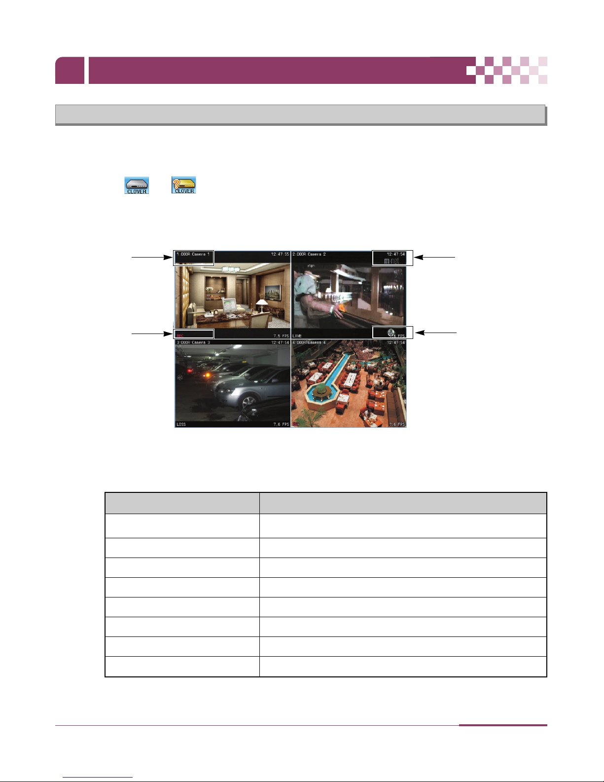
71
DIGITAL VIDEO RECORDER
CLIENT PROGRAM-
CLViewer
Ⅸ
3.4. Live Viewing
(1) If one DVR is connected, live images will be displayed automatically when entered the Set Name, IP (or Host Name: e.g.
L50F9AB.DVRHOST.COM), Port number and Password in the SET LIST MANAGER.
(2) Double click “ or ” or use Virtual DVR (refer to section 4. Virtual DVR on page 79) to view live images when more
than 2 DVRs are connected.
(3) On-Screen Indicators
There are four types of on screen indicators. OSD ON or OFF can be selected on the CLViewer.
1) Camera Title : Displayed in the following orders: Camera Number-Camera title
2) Time : Displays time.
3) DVR Status: Displays REC, Network connection, Video Loss, Event, and Current Status.
Camera Title
DVR Status
Frame Rate
REC Normal Recording
Wait At the initial connecting
Loss Video Loss
Close Disconnected from DVR
Alarm Alarm Recording
Motion Motion Recording
PB Playback for selected channel.
Live Live viewing
Indicator Condition
4) Field per Second: Network transmission speed. The transmitted field rate is Different form the20 DIGITAL VIDEO RECORDER
actual recording field rate of the DVR.
Time

72
DIGITAL VIDEO RECORDER
CLIENT PROGRAM-
CLViewer
Ⅸ
(4) Multi-screen Display
Click the individual multi-screen buttons to display corresponding multi-screen.
(5) Change the camera position
Click and drag any camera to the desired camera position to change its position.
(6) Full Screen Display
There are two ways to enable Full Screen display.
1) Select any camera for Full Screen display by double-clicking the window of a desired camera.
(To switch back to the previous Live viewing mode, double-click again.)
2) Select any camera for Full Screen display by right-clicking the mouse and click the message “FULL SCREEN“.

73
DIGITAL VIDEO RECORDER
CLIENT PROGRAM-
CLViewer
Ⅸ
3.5. Context Menu
The context menu allows accessing the submenus for the channel, DVR and the Virtual DVR.
(1) To view a channel in full screen, right-click your mouse or double click the desired channel.
(2) There are 6 items in the context menu for each DVR.
1) LIVE: Live display for a selected DVR.
2) PROPERTY: DVR information
3) CLIENT LOG LIST
4) DVR LOG LIST
5) SETUP: See “DVR Menu Setup”
6) REMOVE: Removes the selected DVR from DVR Window.
LIVE
Click right button on mouse

3.6. Playback
74
DIGITAL VIDEO RECORDER
CLIENT PROGRAM-
CLViewer
Ⅸ
DVRs that have been added onto the DVR window using the SET LIST MANAGER can be accessed in Playback Mode for remote playback
or for downloading files to the remote PC. Unlike the live mode, only one DVR can be accessed at a time.
(1) To start playback, press PB button .
(2) It will be switched to Playback Mode, as shown below.
(3) When button is pressed, Remote Search Menu will appear.

75
DIGITAL VIDEO RECORDER
CLIENT PROGRAM-
CLViewer
Ⅸ
(4) Press button, or button for playback.
1) Remote Playback
Remote Playback allows users to directly play stored video through the CLIENT.
Press button, and select a DVR.
Remote Search shows a graphical representation of the recorded video stored on the DVR. The Data are organized in color by
category: Alarm (Red) > Motion (Green) > Normal (Yellow).
Select desired Date and Time by clicking the mouse. Click and drag “Hour or Minute’s Bar toward right-hand side to set longer
minutes. Click “Play” button to start playback.

76
DIGITAL VIDEO RECORDER
CLIENT PROGRAM-
CLViewer
Ⅸ
2) Remote Download
Remote Download allows users to download and save data on remotely connected computer through the CLViewer.
Select button, and choose a DVR.
Remote Search shows a graphical representation of the recorded video stored on the DVR.
Select desired date and time by clicking the mouse. Click and drag “Hour or Minute’s Bar toward right-hand side to set longer
minutes. Click “Download“ button to save the recorded data to your computer (on “C:\Program Files\CLViewer\Download“).
Download directory can be changed in the CLViewer Setup Menu.

77
DIGITAL VIDEO RECORDER
CLIENT PROGRAM-
CLViewer
Ⅸ
a. BEGIN END: Indicates the Start time and End time of selected File.
b. CURRENT : Indicates the time of current downloaded file.
c. Download Cancel : Select
d. Download Complete: “Download Complete” will appear after the download has been completed,
as shown below. Click
3) LOCAL
Local Menu is mainly used to review downloaded data from a DVR through the CLViewer.
Select button.
Local Search shows a graphical representation of the stored file on your PC.
Select desired DVR, Date and time, then click button to start playback.
: Delete a selected file from your PC.
: Save a selected file to another folder or drive on your PC.
: To review downloaded files on PC or back-up file in USB memory stick

78
DIGITAL VIDEO RECORDER
CLIENT PROGRAM-
CLViewer
Ⅸ
4) How to play back-up file in USB memory stick.
By Local Search
- Click “Open File” on Local Search and click Index file as shown below.
- Click “Open” and the back-up file in USB memory will display.
By MCD Player
See section 2. How to play back-up data in USB memory stick in your PC on page 47.
3.7. DVR Menu Setup
- DVR Menu Setup allows modification of various system settings of your DVR.
- DVR set up can be accessed through the context menu from any DVRs
- Select any DVR for Menu setup. Context Menu will appear on screen by right- clicking on the selected DVR.
Click right button on mouse

79
DIGITAL VIDEO RECORDER
CLIENT PROGRAM-
CLViewer
Ⅸ
4. Virtual DVR
4.1. What is Virtual DVR.
Virtual DVR is not an actual DVR, but a group of several DVRs already listed in the DVR window. For each Virtual DVR set, up to 64
DVRs can be added, pulling one camera from each DVR. The Virtual DVR behaves in the same way a DVR would, except for the
warning notifications.
If you would like to access only one DVR system through the CLViewer, it won’t be necessary
for setting up the following steps (skip the following section).
4.2. Virtual Set List Manager
Access Virtual Set List Manager to add or delete a Virtual DVR set to the CLViewer.
Click button to start the Set List Manager. Set List Manager menu will be displayed, as shown below.
Click
1
2
(1) ADD to CLIENT List
Follow the steps to set up Virtual DVR.
1) NAME: Enter a Virtual DVR title to be displayed in the CLViewer window.

80
DIGITAL VIDEO RECORDER
CLIENT PROGRAM-
CLViewer
Ⅸ
* Auto Arrange :
- Check this option to have the CLViewer arrange cameras with any of the events occurring from a virtual DVR with
registered cameras. The cameras with events are moved to channel 1 automatically, then arranged in the order of priority.
* Auto Insert& Arrange :
- Check this option to have the CLViewer to add, prioritize and arrange cameras with any of the events occurring from any
cameras.
* Alarm/ Motion/ Video Loss:
- Check these options to have the cameras with alarm/motion triggers or Video Loss to be prioritized and arranged
automatically in either Auto Arrange or Auto Insert & Arrange.
2) ADD VIRTUAL DVR: Click “Add Virtual Set” button to create Virtual DVR. Avoid using the same name for the sets.
3) Save changes and exit the menu : Select “OK”
4) Exit the menu without change : Click “Cancel”
- APPLY: To apply the changes to the selected Virtual DVR.
(2) DEL VIRTUAL DVR: Delete a selected virtual DVR from the CLIENT list.
(3) PROPERTY : This menu provides information such as Virtual Set Name, Total number of connected DVR, Total number of selected
Cameras and IP information of connected DVRs.
4.3. Editing Virtual DVR
(1) Choose a Virtual DVR and double click.
(2) The selected Virtual DVR will be activated, and an indicator, “” will be displayed.
(3) Select a divided screen on the CLViewer to Display.

81
DIGITAL VIDEO RECORDER
CLIENT PROGRAM-
CLViewer
Ⅸ
(4) There are two ways to add cameras.
1) Whole cameras of desired DVR .
Click the desired DVR and drag it to the desired position.
The camera will be added in numeric order from the selected channel to the end, depending on the number of connected
cameras on your DVR.
In the following examples, 4 Ch DVR has been dragged to channel Number 4.
2) Any selected camera on DVR.
Click any DVR in the DVR Window while Virtual DVR is activating.
After a camera icon is displayed, drag the camera to the desired channel/position.
In the following examples, Camera No 1 on Clover DVR has been dragged to Channel No 8.
②
③
①
NOTE
The new camera will replace the existing camera if there is any conflict.

82
DIGITAL VIDEO RECORDER
CLIENT PROGRAM-
CLViewer
Ⅸ
(5) Delete cameras.
There are two ways delete a camera from the CLViewer.
1) Select any camera during live monitoring. Right click to display Context Menu. Select “REMOVE“
2) Select a camera, and drag it to the DVR window or the Virtual DVR window.
4.4. Live Viewing on Virtual DVR
It is exactly the same as Actual DVR.

83
DIGITAL VIDEO RECORDER
Appendix 1 : HDD INSTALLATION
1.1 INSTALL SERIAL ATA (SATA) HDD (Hard Disk Drive)
DVR manufacturer had installed a 320GB SATA HDD as primary Master in the DVR system. Just in case, refer to the following
explanation on how to install the additional SATA HDD (Hard Disk Drive) as secondary Master.
1. Turn the power off and unplug the AC adapter.
2. Remove the cover by using driver. (Remove the screws on both side and back of the product.)
3. Attach the additional SATA HDD to the bottom (Refer to below). There are four holes on the bottom of the system.
4. Secure the additional SATA HDD with the supplied screws as below.
CAUTION
The power must be turned off before installing.
Additional SATA HDD
FIX SCREW

Appendix 1 : HDD INSTALLATION
84
DIGITAL VIDEO RECORDER
5. Connect the Serial ATA power connector and the Signal cable to the additional SATA HDD.
6. Reassemble the cover.
7. Turn the power on and see if the HDD is being recognized.
NOTE
Be sure that the Serial ATA power connector and the Signal cable are properly connected.
NOTE
- After installing the additional SATA HDD, formatting should be performed on the two HDDs simultaneously
(See section 9-4. DISK on page 38). Back up the important data before formatting the HDDs.
- Be sure that the system recognizes the SATA HDDs in the System menu/INFO as follows.
” INTERNAL HDD: 2 EA, xxx GB (Total space of the two HDDs)”

85
DIGITAL VIDEO RECORDER
Appendix 2 : AVI File Converting
Required Software for PC
1.
AVI Converter: Once you install the Client Software (CLViewer) on your PC, AVI Converter will run, and it will be installed
automatically on your PC. You can find this program in “C:\Program Files\CLViewer“.
2. Codec
ffdshow 3ivx
How to change CMS file to AVI file.
1. Double-click AviConverter in “C:\Program
Files\CLViewer“. Choose a file to convert and click
“Open“ button.
2. Choose a folder to save.
3. Choose a channel to convert.
4. Click “Convert“ button to start the process.
(You can see the processing status at Status bar.)
5. To play, double-click one of AVI files.
1
2
3
4
Codec Download URL
ffdshow http://www.digital-digest.com/software/download
3ivx http://www.3ivx.com/download

86
DIGITAL VIDEO RECORDER
APPENDIX 3 : Specifications
Specifications 4CH
Video Input 4
Video Output Composite, VGA, SPOT-OUT
Compression MPEG 4
Live Display Resolution NTSC 720*480, PAL 720*576
Alarm In/Out(Relay) 4/1
Operating System EMBEDDED LINUX
System Control Key buttons, IR Remote Controller, Remote CLViewer software
Live Display Speed 4ch Real Time
Maximum NTSC 30 fps 720 x 480 ,60 fps 720 x 240, 120 fps 360 x 240
Recording Speed PAL 25 fps 720 x 576 ,50 fps 720 x 288, 100 fps 360 x 288
Audio Record 1 IN, 1 Out
Features
Display Brightness, Contrast, Color Adjustments Per Channel
Camera Title 12 Characters per Channel
Recording Mode Manual, Schedule, Alarm, Motion
Recording Method 5 Levels of Compression Rate / Record Frame Rate Adjustment
Recording Adjustments Pre-Alarm: 3 sec/ Post-Alarm: 2 sec. ~10 sec.
Motion Detection Per Channel 4*4 Grids (SET)/ 28 x 24 (CLIENT)/ 20 Sensitivity Levels
Search Mode Date & Time, Camera , Alarm / Motion
Playback Modes Forward & Reverse: Pause, Frame by Frame, Normal Speed, 2X, 4X, 8X, 16X
Multi-tasking Simultaneous Live Display/ Playback, Record or Back-up, Remote Transmission
Watchdog Power Failure Recovery: Auto Reboot / Maintaining Previous Record Settings
Watermark Provided
Back Up USB Flash Memory Stick
Interface RS422, Ethernet(10/100 Base-T), USB 1.1
HDD 2 INTERNAL HDDS
Network LAN, WAN, Internet,
Remote Client Software (CLViewer), Internet Explorer

87
DIGITAL VIDEO RECORDER
APPENDIX 4 : Limited 2 Year Warranty
This warranty gives the original purchaser specific legal rights and may also have other rights, which vary from state to state. If our products
do not function because of any defect in material or workmanship, we will repair free of charges for 2 year on parts and labor from the date
of original purchase. This warranty does not cover modification, abuse, incidental or consequential damages unless the state of owner’s
residence specially prohibits limitations on incidental or consequential damages.
APPENDIX 5 : How to Obtain Factory Service
1. Original purchaser must fill out a warranty card and mail it to the factory with model number, serial number and the date of purchase.
2. We will repair or replace, and return to the owner of the system under this limited warranty.
3. Please pack the system carefully and securely using the original packing materials, and send it prepaid and insured to:
13073 E. 166thSt. Cerritos, CA 90703
4. Please include a check for $30.00 to cover the cost of return postage and handling. If the system is returned within the warranty period,
please include a proof of purchase. If the system is out of warranty, you will receive an estimate of the repair cost for your approval before
repair work will be started.

88
DIGITAL VIDEO RECORDER
 Loading...