

Page 1

USER’S INSTRUCTIONS
Stand-Alone 4channel
DIGITAL VIDEO RECORDER
MODEL CDR4010
Page 2

CO
NTENTS
1. About this manual---------------------------------------------- 4
2. Unpacking------------------------------------------------------ 4
2.1 Stand-alone DVR Units ------------------------------- 4
2.2 DC 12V SMPS Adapter ------------------------------- 4
3. Features--------------------------------------------------------- 4
4. What to do at the time of installation
5. Specifications--------------------------------------------------- 6
6. Installation------------------------------------------------------- 7
6.1 Controls and Connectors------------------------------- 7
6.2 System connection------------------------------------- 9
6.3 Installation----------------------------------------------- 10
7. How to operate------------------------------------------------- 13
7.1 General information------------------------------------ 13
7.2 Configuration of the front of the unit------------------ 14
7.3 Basic configuration of the monitor display----------- 15
7.4 Live ----------------------------------------------------- 15
7.5 Recording----------------------------------------------- 17
7.6 Replaying----------------------------------------------- 19
8. Setup ----------------------------------------------------------- 21
8.1 Setup displays tree------------------------------------- 21
8.2 How to set up DVR-------------------------------------- 23
8.3 Setup --------------------------------------------------- 23
8.4 Alarm --------------------------------------------------- 23
8.5 System -------------------------------------------------- 26
8.6 Video --------------------------------------------------- 34
8.7 Record -------------------------------------------------- 36
8.8 Display -------------------------------------------------- 41
8.9 User Account ------------------------------------------- 43
9. Installation of additional HDD---------------------------------- 44
9.1 Standard built-in HDD---------------------------------- 44
9.2 Installation of an additional HDD---------------------- 45
------------------------ 5
- 2 -
Page 3

10. NTSC/PAL Selection-------------------------------------------- 46
10.1 PAL/NTSC Selection------------------------------------ 46
11. Networking ----------------------------------------------------- 46
11.1 Requirements ------------------------------------------- 46
11.2 Loading the host program to PC ---------------------- 47
11.3 Cable connection ------------------------------------- 47
12. Networking 1:1 between PC and DVR ----------------------- 47
12.1 DVR Setting --------------------------------------------- 47
12.2 Connecting to a LAN using TCP/IP ------------------- 49
12.3 Setting up PC host program --------------------------- 50
12.4 Connect with network --------------------------------- 51
12.5 Function of buttons ------------------------------------- 54
13. Warranty information------------------------------------------- 61
14. How to obtain factory service--------------------------------- 61
APPENDIX -------------------------------------------------------------- 62
1. Recording time table -------------------------------------- 62
2. Factory default table -------------------------------------- 62
FAQ ------------------------------------------------------------------- 65
- 3 -
Page 4

1. About this manual
This is the User’s Manual for 4ch stand-alone type DVR (Digital Video Recorder).
Please read this manual thoroughly to ensure correct use.
2.
Unpacking
Care should be taken when unpacking to avoid damaging the unit.
Please check that the following items are included:
- DVR main unit
- All Accessories: Bracket, Power cable, DC 12V SMPS Adaptor
- User’s Manual
2.1 Stand-alone DVR (Digital Video Recorder)
Stand-alone DVR can record the video signals from 4 cameras to the built-in HDD and replay
them at real time or at 1~64x speeds. This system has numerous monitoring features such as
automatic seque n ti a l disp la y, ful l sc r ee n display for a selected input video signal, pausing, 2x
digital zooming, quad splitting, etc. Additionally, real time monitoring, replaying and
buzzer/light alarming are possible via network (TCP/IP).
2.2 DC 12V SMPS Adapter
Use only the adapter provided or specified by the manufacturer. Use of non-approved
power adapter may damage the unit and or result in accidents or fi re. Use of such a nonapproved devise could void the warranty.
Input: AC 90~265V 50/60Hz
Output: DC 12±0.5V MAX3.5A
Ripple: Below ±50mV
3. Features
Titling for each quad display, dwell time setting for automatic sequential channel
switching and alarming against signal loss.
This unit inc orporate s powerful recording modes including automatic motion
detection w hich enables a utomatic prolonged reco rding time.
Wavelet algorithm adopted by DVR achieves very high compression ratio while
enabling high resolution compression and decoding.
Very easy to operate.
Easy to install, just connect cameras to DVR and power up the unit.
Remote controlling is available via TCP/IP networking.
Recorded data can be transmitted to a computer and any captured image can be
printed.
- 4 -
Page 5

4. What to do at the time of installation
DVR should be installed in the following order:
1. Make sure all the required hardware is available.
DVR unit
Up to 4 cameras (including power source)
CCTV monitor (or TV set)
Network cable if connecting to a PC
2. Connect the cameras, the DVR un it and monitor (Refer to Fig 6-3).
3. Connect the AC power supply (SMPS) to the DVR.
4. Confirm live video is displayed on the monitor before going to the next step.
5. Select Set Menu and set current date and time. (Refer to 8.setting).
6. Run FACTORY DEFAULT menu on the SYSTEM menu.
7. Perform HDD formatting.
8. Escape from set Menu.
9. Set values for required options.
10. Network cable should be connected to the DVR unit before turning the power on.
Refer to Fig 6-7 for the cable specification.
- 5 -
Page 6

5. Specifications
VIDEO SIGNAL
VIDEO
FEATURES
RECORD
REPLAY
PAN/TILT
HDD IDE (7200rpm) 120 GB (Built in) + 1 HDD (Vacant)
DC POWER External Adapter DC12V SMPS
AC POWER
CONNECTOR
ENVIRONMENT
Free voltage
Design and specifications are subject to change without notice.
Television System NTSC PAL
Refresh Rate 60 field/sec 50 field/sec
Digital Memory 720x484 720x572
Video Inputs 4 Cameras
Video Input Signal 1.0 Vp-p Composite, 75 Ohms
Video Outputs
Video Output Signal 1.0 Vp-p 75 Ohms
Zoom 2 times real time Digital
Freeze Each 4 Camera
PIP PIP Window
Display Format 1 screen, quad, 1+3(1/3,2/3 Scale)
Video Loss Indicate Alarm with Blue screen
Border Line Thickness, Color
Recording Speed
Compression rate 4:1 ~ 250:1
Algorism Wavelet
Recording (Timer, Alarm, Manual) + Motion
Material HDD (Over Write)
Time or Event
RS232C 4 Cameras
Ethernet (TCP/IP) 10/100Mbps REMOTE
RS232C 1200bps ~ 115200bps
(100~240V, 50~60Hz)
Video Inputs 4 BNC
Looping Outputs 4 BNC
Main monitor Output 1 BNC, 1 Y/C
Extra monitor Output I BNC
Alarm In/Out 8-pin Terminal
Ethernet RJ45
RS232C DSUB9
19 inch, 1U(Standard) (H)44 x (W)420 x (D)300 (mm) MECHANICAL
Weight 8.7Kg(Rack type)
Operating
Temperature
Humidity 10 ~ 90%
4 Looping camera signal, 1 Main monitor,
1 Extra monitor, 1Y/C
1 Frame/sec ~ 120
Frames/sec
Normal (real speed), Pause, Step
Forward, Step Backward, Fast Forward
(1~64 times), Fast Backward (1~64 times)
Approx. 35W Consumption
0 ~ 60 deg C
1 Frame/sec ~ 100
Frames/sec
Fig. 5-1
- 6 -
Page 7
6.
Installation
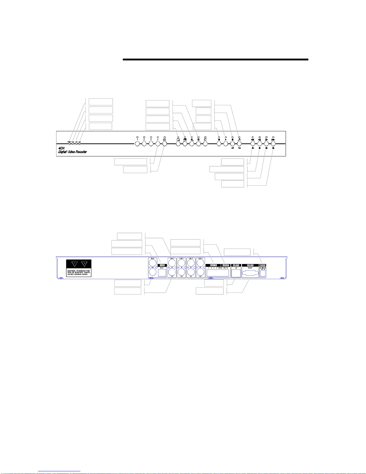
6.1 Controls and Connectors
Power LED
HDD
LAN LINK
LAN DATA
Choose 1~4Ch,
Split Screen
Fig. 6-1(Front)
BNC INPUT
S-VHS MONITOR
MAIN MONITOR
Screen fixed
Screen
Seq. Screen
PIP Screen
ALARM
ALARM INPUT
SETUP
Stop
Play
Recording
Quick Rew.
Seq. Screen Rew.
Seq. Screen
Quick Play
POWER INPUT
AUX MONITOR
LOOP
Fig. 6-2(Rear)
Unpacking the unit
DVR unit (including o ne built-in HD D)
►
AC adapter (SMPS)
►
AC power cord
►
Rack mounting bracket and bolts.
►
User’s Manual
►
PC program CD or diskette for remote control.
►
- 7 -
LAN
RS232C PORT
Page 8

Note : Contact the dealer immediately if any components are
Notes for installation
Install the s ystem according to the instructions su pplied in this manual.
►
This product is designed for indoor use and should not be used outdoors.
►
Avoid any area with high humidity or dust which can shorten the life the unit.
►
Choose a well ventilated area and keep a minimum of 30㎝ away from
►
obstructions. Do not place unit near heat generating devices. Do not place
items on the unit.
Avoid any area with movement as this can interfere with the internal Hard Drive.
►
Use a compatible input/output signal type of cameras and monitor.
►
Contact your dealer if you are having any difficulty. The Warranty may be
►
voided in case of unauthorized disassembling or modification.
missing.
- 8 -
Page 9

6.2 System Connection
Fig. 6-3
- 9 -
Page 10

6.3 Installation
Camera Connection
Connection of cameras
►
Connect the cameras to Video Input (BNC connector) on the back of the unit
as shown in above Fig. 6-4
Connection of Loop Output
►
The
Monitor Connection
►
Connect the monitor to “ Main” on the upper part of BNC connector.
►
►
Camera or video output is available from the Video Output (Loop Output)
on the back of the unit. (When BNC jack is connected to the Video Output, the
termination resistance (75Ω) is automatically switched to impedance statu s so
the external device must have termination resistance.)
Connection of main monitor
Connection of auxiliary monitor
Connect the monitor to “Aux” on the lower part of BNC connector.
The output of auxiliary monitor is the same as the main monitor. For the unit is
equipped with a separate output buffer, so it works inde pendently from the
main monitor.
Connection of S-VHS monitor
Connect the S-VHS monitor to “S-VHS” DIN jack on the rear of the unit.
It works independently from the main monitor.
Pin configuration of S-VHS connector.
►
Fig. 6-4
Connection of Sensor and ALARM OUT
Connection of alarm (ALARM IN)
►
Connect the sensor to ALM (Alarm) IN.
The sensor should be contactor type and support NO (Normally Open). Refer to
Fig. 6-5 for connection.
Connection of ALARM OUT
►
- 10 -
Page 11
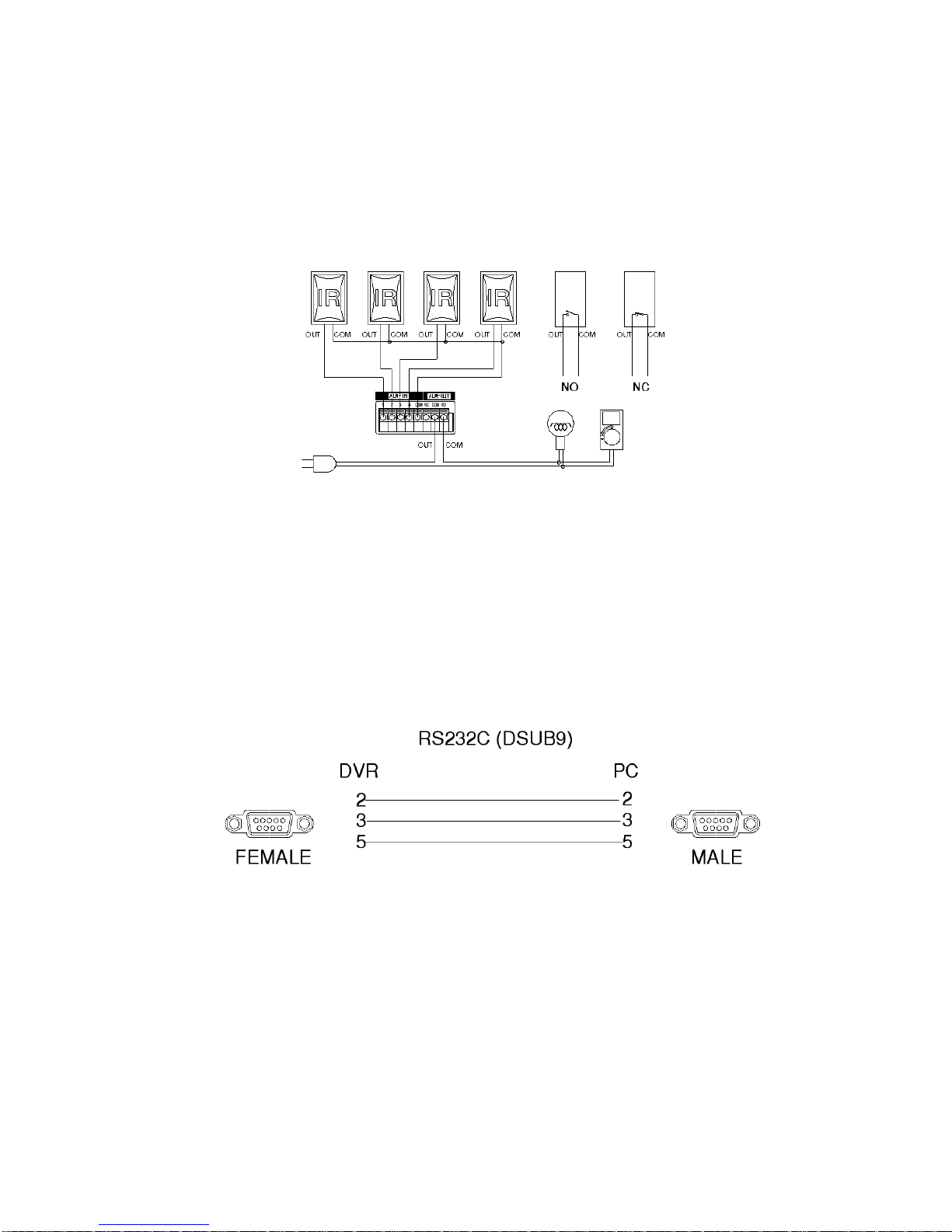
When necessary, use ALM OUT. The output of ALARM OUT is a relay contactor
type and supports NO. or NC. The output capacity is 220V 1A and a higher
capacity can cause system failure.
Refer to Fig. 6-5 for the connection to ALARM OUT.
Fig. 6-5
Connection to RS232C
► Connect the cable to RS232C. Our RS232C connector is a DSUB9 type.
The maximum cable length is 50’. When you want to use a longer cable, use
the RS232 to RS485 converter.
Refer to Fig. 6-6 for connector pin configuration.
Connection to Ethernet
Connect the cable to Ethernet. Our Ethernet connector is a RJ45 type. The
►
maximum cable length is 300’. When you want to use a longer cable, you must
use a repeater. Refer to Fig. 6-7 for connector pin configuration.
Fig. 6-6
- 11 -
Page 12
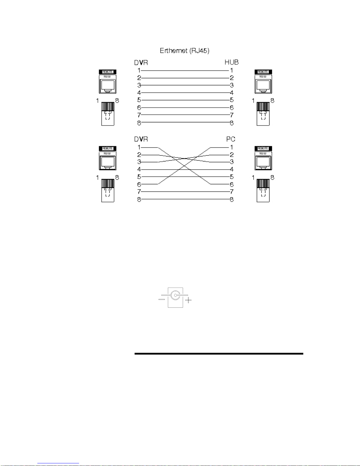
Power connection
Connect the supplied power unit to the DC power jack on the rear of CDR4010.
►
Specificat ion of SMPS adapter
►
Input : AC90 ~ 230V, 50/60Hz
Output
: DC12V, 3.5A
Fig. 6-8 (Polarity of power jack)
7. How to operate
7.1 General information
You can operate all functions of the system by use of the 18 buttons located on
►
Fig. 6-7
the front panel. Additionally, you can remotely control this unit
- 12 -
Page 13
via RS232C or the Ethernet port located on the back side.
The system status is indicated by either LED light on the operator buttons or the
►
monitor.
The system is protected from any inadvertent pressing of any operator buttons.
►
But care should be taken when u s ing the functions of HDD Formatting of
ALARM List Deletion as then can lead to data loss. To avoid any mistakes, the
re-confirmation is required when these functions are selected.
-
- REPLAY Mode
- SETUP Mode
The system has the following 4 operating modes;
►
LIVE Mode
RECORD Mode
-
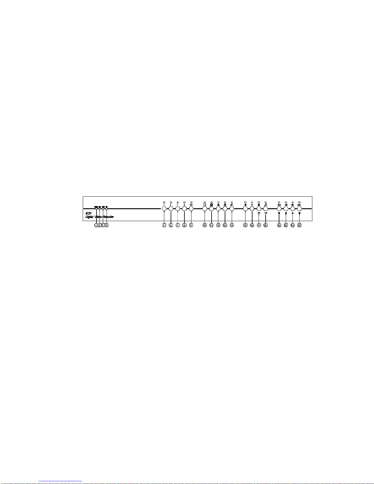
7.2
Fig. 7-1
Configuration of the front panel of the unit
1) POWER status display LED
2) HDD status display LED
3) Ethernet LINK status display LED
4) Ethernet DATA status display LED
5) Ch1 (Channel selection)
6) Ch2 (Channel selection)
7) Ch3 (Channel selection)
8) Ch4 (Channel selection)
9) QUAD (QU A D/Mode selection)
10) PIP (Picture-in-picture)
11) SEQ (Sequential display)
12) ZOOM (2 x Zoom)
13) FREEZE (Freeze)
14) OSD/ALARM (OSD ON/OFF)
15) REC (Recording), KEY for ALARM list (refer to Page 20)
16) PLAY/PAUSE (Play / Pause)
17) STOP/ESC (Play stop and Escape)
- 13 -
Page 14
18) SETUP/ENTER (System setup mode/ Execution)
19) REW (Rewinding),
UP (one of navigation keys): No LED lit
20) PREV (Progressive rewinding), DOWN (one of navigation keys): No LED lit
21) NEXT (Progressive play), LEFT (one of navigation keys): No LED lit
22) FF (Fast forward), RIGHT (one of navigation keys): No LED lit
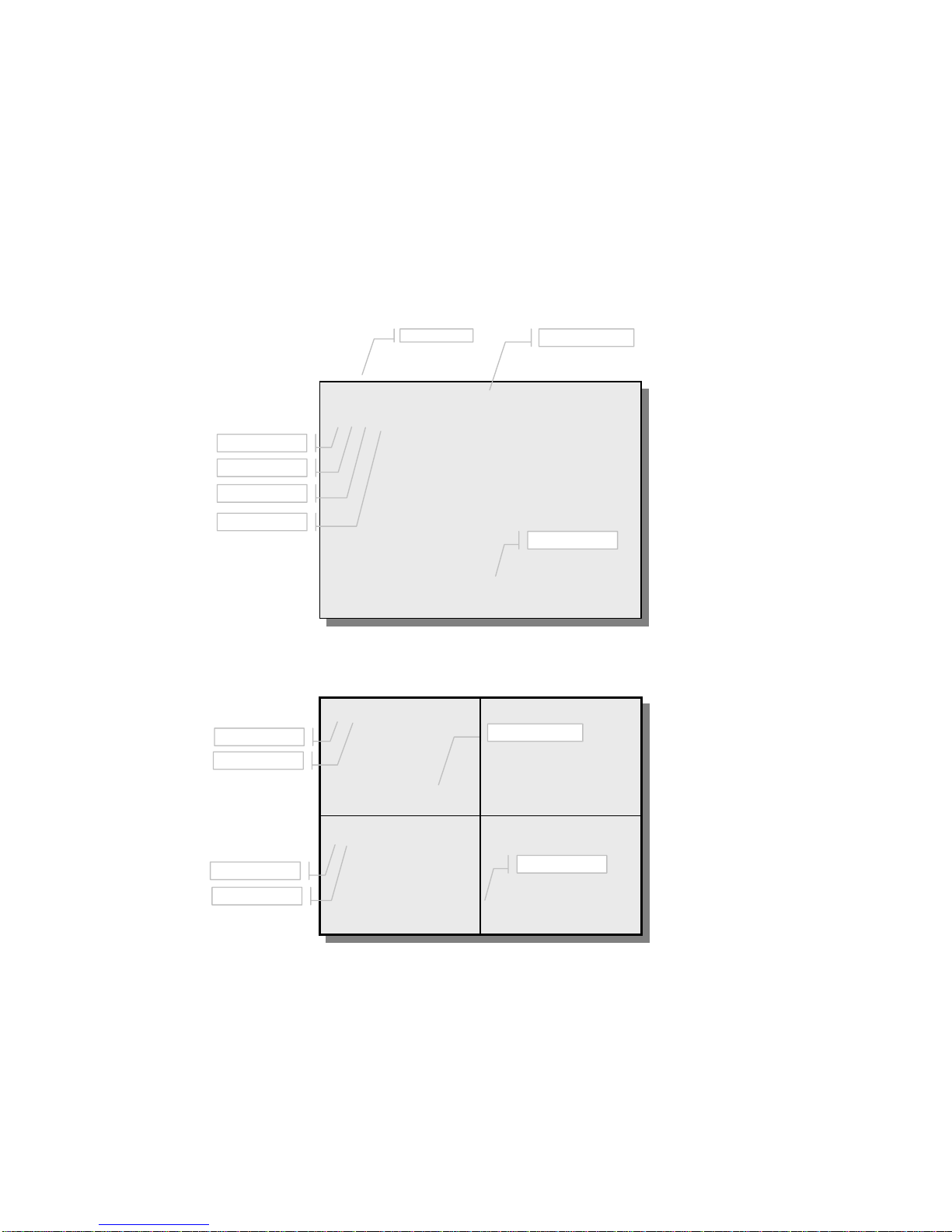
7.3 Basic configuration of the monitor display
Motion detection
Sensor input
Freeze
Zoom
PLAY CAM 1
M S F Z
2004/08/10 18:16:57
Fig. 7-2
Motion detection
Sensor input
Freeze
Zoom
M S
F Z CAM 1 CAM 2 F Z
F Z CAM 3 CAM 4 F Z
2004/08/10 18:16:57
Mode
Full Screen display
Camera #
Date and time
Camera #
Date and time
- 14 -
Fig. 7-3 Quad display (4 equal split)
Page 15
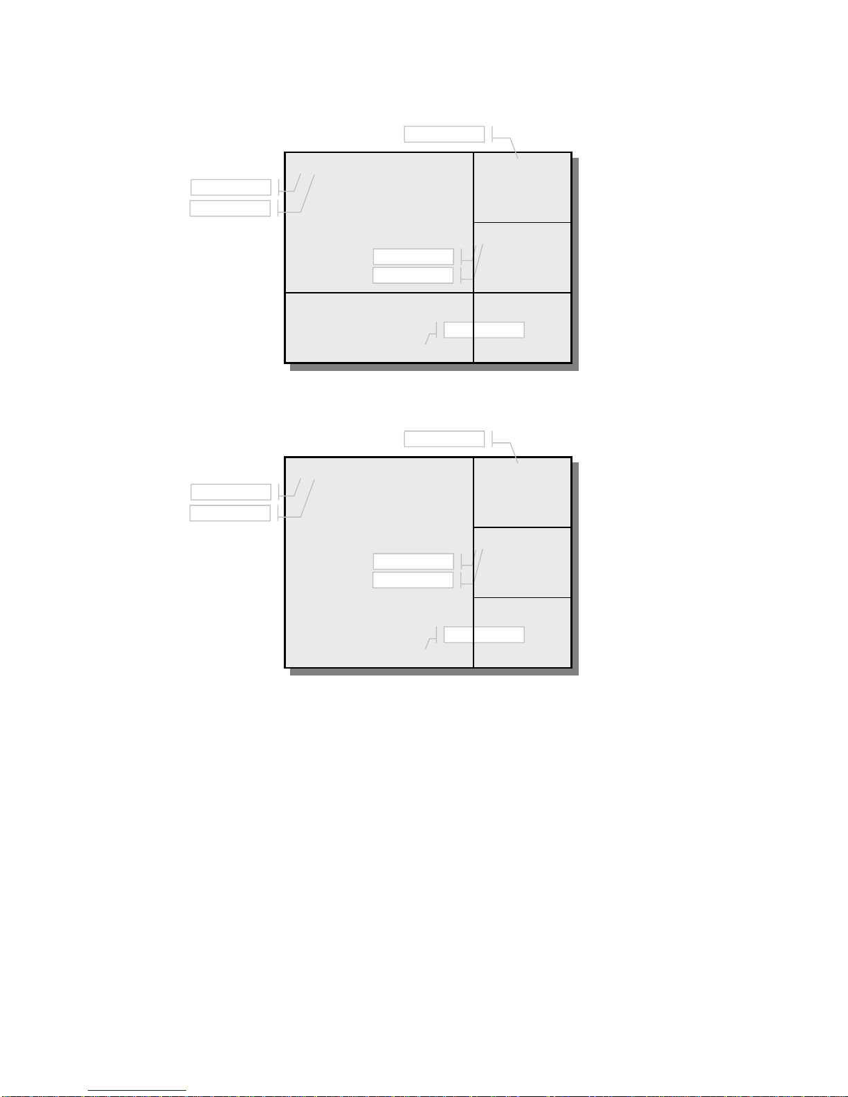
Motion detection
Sensor input
M S CAM 1 FZ CAM 2
FZ CAM 3
FZ CAM 4
2004/08/10 18:16:57
Camera #
Freeze
Zoom
Date and time
Fig. 7
Quad display (2/3+3 split
-4
)
Motion detection
Sensor input
M S CAM 1 FZ CAM 2
FZ CAM 3
FZ CAM 4
2004/08/10 18:16:57
Camera #
Freeze
Zoom
Date and time
7.4 LIVE
Live means viewing the present video images from the cameras on the monitor.
LIVE MODE
Full screen display
►
Full screen display is possible in the Live mode or Record mode.
Use any channel selection button to choose a corresponding video input.
Quad display
►
All 4 cameras are viewed on the monitor at the same time in reduced size.
The quad display is possible in the Live mode or Record mode.
- 15 -
Fig. 7-5 Quad display (Full + 3 split)
Page 16

Press the QUAD button repeatedly to view the different quad display like Fig. 7-4
or Fig. 7-5.
Sequential display
►
sequential display is possible in the Live mode or Record mode.
The
Press the SEQ button.
PIP (Picture in picture) display
►
The PIP is possible in the Live mode or Record mode.
Press the PIP button.
The main display remains the same while 4 video inputs are consecutively
selected by pressing the PIP button.
The
►
The Zoom display is possible in the Live mode or Record mode (This does not
When the ZOOM button is pressed in the Full disp lay mode, a part of th e
Choose the ar ea to be zoomed by using the navigation key.
Press the ZOOM button again to release the zoom function.
►
PIP button is released when any channel selection button is pressed
ZOOM Display
work in the SEQ or QUAD mode).
screen is silhouetted.
Press the ZOOM key to get 2 x digital zoom for the selected area.
Press the navigation key for panning or tilting.
FREEZE
.
Freeze is possible in the Live mode or Record mode.
In the Full screen mode
- Press the FREEZE button to freeze the current display.
- Press the FREEZE button again or press other channel selection buttons to
release the Freeze function.
In the Quad mode
- When the FREEZE button is pressed, all 4 displays enter into freeze standby
mode.
-
corresponding part on the screen.
- Press the same channel sel e ction button to release the fre eze function.
- Press the FREEZE button again to release the freeze standby function of all
the displays.
OSD ON/OFF (OSD ; On Screen Display)
►
- Available in the LIVE, RECORD Mode or REPLAY Mode.
Press any channel selection button to get a frozen display of
- 16 -
Page 17

- When the OSD button is pressed, all the texts except for the video display
are deleted temporarily.
When the button is pressed again while OSD is in OFF pos ition, the system
-
status will be displayed.
- Pressing the OSD button again will bring the system to normal condition.
PAN/TILT camera control
►
Choose SYSTEM in the SETUP menu with the navigation keys and press the ENTER
button.
Choose
ENTER button. Press the E N TER button and choose a PAN/T ILT camera with the
navigation keys. Press the ENTER button again.
The FULL screen display, PAN/TILT and FOCUS/ZOOM functions will be controlled
by channel 1 to 4 buttons.
- PAN/TILT control
- FOCUS/ZOOM control
RS-232C
When the channel 1 (or 2, 3, 4) button is pressed in the channel 1 FULL
screen display mode, it will be PAN/TILT control mode and displayed PAN-
TILT CONTROL
Press UP key for TILT UP, DOWN key for TILT DOWN, LEFT key for PAN LEFT and
RIGHT key for PAN RIGHT.
When the channel 1 (or 2, 3, 4) button is pressed in the PAN/TILT control
mode, it will be FOCUS/ZOOM control mode and displayed FOCUS-ZOOM
CONTROL instead of PAN-TILT CONTROL on the screen.
Press UP key for ZOOM IN, DOWN key for ZOOM OUT, LEFT key for FOCUS
and
NEAR
Press the channel 1 (or 2, 3, 4) to go back to channel 1 (or 2, 3, 4) FULL
screen display mode.
in the
RIGHT
SYSTEM
instead of camera title on the screen.
key for
menu with the navigation keys and press the
FOCUS FAR
.
7.5 Recording
How to record
Manual recording
►
Timer recording
►
Alarm recording
►
- Possible in the LIVE or RECORD mode
- 17 -
Page 18

Manual recording
The recording will start when the REC button is pressed. While the unit is
►
recording, the REC button will be lit and ‘REC’ will blink on the screen.
Press the REC button again to stop recording. The light of REC button will go off
►
and ‘REC’ display on the monitor will disappear.
Selecting recording mode
►
While the unit is rec ording in the TIMER RECORD mode there may be some
occasions recording needs to be stopped for some reason, for instance, to
view the recorded images. After that, when the REC button is pressed to restart
recording the below window will be displayed.
Choose the TIMER RECORD START to return to the TIMER RECORD mode or
MANUAL RECORD START to go to the MANUAL RECORD mode. When the
MANUAL RECORD START is selected, the recording will conti n ue until the REC
button is pressed again.
Timer recording
Timer recording by day of weeks.
►
- The recording by week days (Monday ~ Friday), Saturday and Sunday is
possible.
- The time of record start and finish can be set to hour:minute.
- Refer to 8. Setup (SETUP>RECORD>TIMER RECORD) for more details.
Timer recording by Specific days.
►
- Up to 32 record time zones can be set.
- The Time of record start and finish can be set to year:month:day:hour:minute.
- Refer to 8. Setup (SETUP>RECORD>TIMER RECORD) for more details.
ALARM recording
When an alarm signal is received, the system begins to record automatically.
►
When the alarm signal is stopped, the system continues recording for the
►
ALARM DWELL time and finishes the recording.
- 18 -
Page 19

TIMER RECORD START
MANUAL RECORD START
PRESS REC KEY TO TIMER REC
7.6 Replaying
Replay Mode (Press Play button)
Replaying from set recording time.
►
Replaying by alarm lists.
►
Replaying from set recording time
When the Play button is pressed again after setting the REPLAY TIME, the
►
RECORD SELECT
Fig. 7-6 Record Select Setup
replaying will begin.
PLAY
RECORDED TIME
2004/08/10 02:18:29
2004/08/10 02:18:29
REPLAY TIME
2004/08/10 02:18:29
ALARM LIST : 0 of 0
NONE ALARM RECORDED
Fig. 7-7 Replay Start
At first, the REPLAY TIME that is shown is the record start time.
►
Next, the REPLAY TIME shown i s the last moment when the previous replayi ng
►
ended.
Press the STOP/ESC button to return to the LIV E mode.
►
Record Start
Record finish
Replay Start
- 19 -
Page 20

Setting REPLAY TIME
►
- Set the time by using the navigation keys: use the up/down keys for
changing the values, the left/right keys for moving to next fields.
- Set the time in the order of second→minute→hour→day →month →year.
- The REPLAY TIME can not be out of the RECORD TIME zone.
Replaying by alarm list
Press the REC button to move between the REPLAY TIME mode and the
►
ALARM LIST mode.
Choose a LIST number with the UP or the DOWN key.
►
Press the Play button to replay.
►
Replaying
Pause
►
- Press the Play button to pause. Press it again to replay.
REW/FF
►
- During replaying, press the REW button for fast rewinding, the FF button for
fast forwarding.
- Repeat pressing the REW or the FF button to accelerate the speed up to 64
times.
PREV/NEXT
►
- During replay, press the PREV button to view the previous frame in still image,
press the NEXT button to view the next frame in still image.
- Keep pressing the PREV or NEXT button for co ntinuous viewing.
Screen selection in R eplaying
During replay, press the 1,2,3 or 4 button (channel selection button) to view
►
only the corresponding video channel. Press the same button again to view 2x
image. Press it again for normal image
Press the QUAD button to view the quad display.
►
The OSD ON/OFF button functions during replaying as well.
►
- 20 -
Page 21

8. Setup
SETUP
ALARM
ALARM LIST
ALARM OPTION
SYSTEM
TIME/DATE
RS
232C
HARD DISK
SYSTEM INFORMATION
NETWORK PERFORMANCE
NETWORK IP CONFIG
8.1 Setup displays tree
ALARM ☞
SYSTEM ☞
VIDEO ☞
RECORD ☞
DISPLAY ☞
USER ACCOUNT ☞
ALARM LIST ☞
ALARM LIST CLEAR
ALARM HOLD : 5 SEC
ALARM OPTION ☞
TIME/DATE ☞
RS-232C ☞
HARD DISK ☞
FACTORY DEFAULT
SYSTEM INFORMATION ☞
NETWORK IP CONFIG ☞
NETWORK PERFORMANCE ☞
REC SPEED : 30 F/S
REC QUALITY : +SVHS
ALARM OUT TYPE : N.O.
ALARM BUZZER OUT : ON
BAUD RATE : 115200
DATA BITS : 8 BITS
STOP BIT : 1 BIT
PARITY BIT : NONE
STAND ALONE 4CH DVR
COPYRIGHT 2002
PRESS ANY KEY TO RETURN
CONNECTION SPEED
MODEM NETWORK
UNDER 56KBPS
-
VER. 2 . 7 . X
001.____ __/__/__ __:__:__
002.____ __/__/__ __:__:__
003.____ __/__/__ __:__:__
004.____ __/__/__ __:__:__
005.____ __/__/__ __:__:__
006.____ __/__/__ __:__:__
007.____ __/__/__ __:__:__
008.____ __/__/__ __:__:__u
TIME FORMAT : 24 HOUR
TIME : 23:44:23
DATE FORMAT : YYYY/MM/DD
DATE : 2004/08/17 TUE
HDD1 : 79.5G 0.0p USED
SELECT DISK AND
PRESS ENTER TO FORMAT
IP MODE : STATIC-IP
GATEWAY ; 192.168.123.0
SUBNET : 255.255.255.0
IP ADDR : 192.168.123.1
MAC ID : 0005B0FFD87B
PORT : 4001
- 21 -
Page 22

DISPLAY
NETWORK USER ID
TIEMR RECORD
WEEK DAY RECORD
C2 MOTION : O
S
ATURDAY RECORD
C2 MOTION : O
SUNDAY RECORD
C2 MOTION : O
HOLIDAYS
HOLIDAYS REC OPTION
VIDEO
RECORD
VIDEO TITLE
V
IDEO CONTROL
PIP POSITION
BORDER LINE
O
COLOR :
INSTALLED VIDEO PORT
CH1 CH2 CH3 CH4
ON ON ON ON
VIDEO TITLE ☞
VIDEO CONTROL ☞
SEQ DISPLAY DWELL : 1 SEC
BRIGHT
CONTRAST
REC MOAD : QUAD
REC SPEED : 30F/S
REC QUALITY : +SVHS
REC MOTION : OFF
MOTION HOLD : 5 SECT
POWER ON REC : OFF
HDD OVERWRITE : ON
TIMER RECORD ☞
WEEK DAY ☞
SATURDAY ☞
SUNDAY ☞
HOLIDAYS ☞
HOLIDAYS REC OPTION ☞
TITLE DISPLAY : ON
TIME DISPLAY : ON
TIME POSITION : BOTTOM
PIP POSITION ☞
BORDER LINE ☞
BORDER TYPE : THIN
RDER
B
DEVICE ID : SDVR
USER ID : ROOT
PASSWORD : ********
PASSWORD : OFF
VIDEO CH1 = CAM1
VIDEO CH2 = CAM2
VIDEO CH3 = CAM3
VIDEO CH4 = CAM4
gg
ggg
DARK GRAY
REC1 TIME
OFF 00:00 – 00:00
REC1 MODE : QUAD
REC1 SPEED : 30 F/S
REC1 QUALITY : +SVHS
REC1 MOTION : OFF
REC2 TIME
OFF 00:00 – 00:00
REC2 MODE : QUAD
REC2 SPEED : 30 F/S
REC2 QUALITY : +SVHS
RE
REC MODE : QUAD
REC SPEED : 30 F/S
REC QUALITY : +SVHS
REC MOTION : OFF
Fig. 8-1 Setup displays
REC1 TIME
OFF 00:00 – 00:00
REC1 MODE : QUAD
REC1 SPEED : 30 F/S
REC1 QUALITY : +SVHS
REC1 MOTION : OFF
REC2 TIME
OFF 00:00 – 00:00
REC2 MODE : QUAD
REC2 SPEED : 30 F/S
REC2 QUALITY : +SVHS
RE
REC1 TIME
FF
OFF 00:00 – 00:00
REC1 MODE : QUAD
REC1 SPEED : 30 F/S
REC1 QUALITY : +SVHS
REC1 MOTION : OFF
REC2 TIME
OFF 00:00 – 00:00
REC2 MODE : QUAD
REC2 SPEED : 30 F/S
REC2 QUALITY : +SVHS
RE
1. OFF 00/00/00 00:00
- 00/00/00 00:00
2. OFF 00/00/00 00:00
- 00/00/00 00:00
3. OFF 00/00/00 00:00
- 00/00/00 00:00
4. OFF 00/00/00 00:00
- 00/00/00 00:00
SELECT TIME AND
PRESS ENTER TO SETTING
FF
FF
- 22 -
Page 23

8.2 How to set up DVR
The setup is possible only in live mode.
Press the MENU key.
Choose a setup item by using the up/down navigation keys and press the ENTER
key. The parameter value will blink.
Choose the desired value by using the up/down navigation keys and press the
ENTER key.
Press the navigation keys to move to the next setup item.
8.3 Setup
SETUP
ALARM ☞
SYSTEM ☞
VIDEO ☞
RECORD ☞
DISPLAY ☞
USER ACCOUNT ☞
Fig. 8-2 Setup Display
8.4 Alarm
Press the MENU button on the front panel of DVR.
Press the ESC button to go back to the live mode .
Choose ALARM in the SETUP menu using the navigation keys and press the ENTER
button. The following menu will be displayed.
ALARM
ALARM LIST ☞
ALARM LIST CLEAR
ALARM HOLD : 5 SEC
ALARM OPTION ☞
- 23 -
Page 24

Fig. 8-3 Alarm set display
ALARM LIST
Fig. 8-4 (Alarm List display)
Choose ALARM LIST in the ALARM menu using the navigation keys and press the
ENTER button. The each page shows 8 alarm lists.
Press the up/down navigation keys to show the previous or next page of lists.
The m
aximum capacity is 128 alarm data.
ALARM LIST
001._2 _ _08/11/04 11:28:31
002.
003.
004.
005.
006.
007.
008.
Channel number
Next page mark
Alarm triggering time
Serial number of
↓
ALARM LIST CLEAR
Fig. 8-5 Alarm List Clear Display
Choose ALARM LIST CLEAR in the ALARM menu with the navigation keys and
press the ENTER button
A message to execute or not is displayed as in Fig. 8-5.
Press the ENTER button again to delete the data. Press the ESC button to canc e l .
ALARM
ALARM LIST ☞
ALARM LIST CLEAR
ALARM HOLD : 5 SEC
ALARM OPTION ☞
PRESS ENTER TO CLEAR
PRESS ESC TO RETURN
.
- 24 -
Page 25

(Care should be take n when pressing the EN TER bu tton as it will dele te the data
ALARM HOLD
ALARM OPTION
permanently)
Fig. 8-6 Alarm List Clear Display
Choose
ENTER button.
Change the time by using the up/dow n navigation keys.
The changeable range is OFF ~ 9 SEC.
Choose
ALARM
ALARM LIST ☞
ALARM LIST CLEAR
ALARM HOLD : 5 SEC
ALARM OPTION ☞
ALARM HOLD
to ignore the alarm signal inputs.
OFF
In the
ALARM
menu with the navigation keys and press the
Fig. 8-7 ALARM OPTION DISPLAY
RECORDING SPEED
►
Choose ALARM OPTION In the ALARM menu with the navigation keys and
press the ENTER button.
Choose REC SPEED in the ALARM OPTION menu and press the ENTER button.
Change the speed by pressing the up/down navigation keys.
REC SPEED : 30 F/S
REC QUALITY : +SVHS
ALARM OUT TYPE : N.O.
ALARM BUZZER OUT: ON
ALARM OPTION
- 25 -
Page 26

The
RECORDING QUALITY
►
Choose REC QUALITY in the ALARM OPTION menu and press the ENTER button.
Choose a video quality among VHS, SVHS and +SVHS. The VHS represents the
lowest quality with highest compression ratio. +SVHS, vice versa.
ALARM OUT TYPE
►
Choose ALARM OUT TYPE in the ALARM OPTION menu and press the ENTER
button.
Select NO (Normally Open) or NC (Normally Close) using the navigation keys
and press the ENTER button.
ALARM BUZZER OUT
►
Choose ALARM BUZZER OUT in the ALARM OPTION menu and press the ENTER
button.
Choose ON or
8.5 System
Changeable range is 1~30 F/S for NTSC and 1~25 F/S for PAL.
using the navigation keys and press the ENTER button.
OFF
SYSTEM
TIME/DATE ☞
RS232C ☞
HARD DISK ☞
FACTORY DEFAULT
SYSTEM INFORMATION ☞
NETWORK IP CONFIG ☞
Fig. 8-8 SYSTEM DISPLAY
► Choose SYSTEM in the SETUP menu with the navigation keys and press the
ENTER button.
This setup is very important and has to be made befo re starting the system.
►
- 26 -
Page 27

TIME/DATE
Fig. 8-9 (TIME/DATE DISPLAY)
TIME/DATE
TIME FORMAT : 24 HOUR
TIME : 19:14:17
DATE FORMAT : YYYY/MM/DD
DATE : 2004/08/09 MON
Choose TIME/DATE in the SYSTEM menu with the navigation keys and press the
►
ENTER button.
TIME FORMAT
►
Choose TIME FORMAT in the TIME/DATE menu with the navigation keys and
press the ENTER button.
Choose either
press the ENTER button.
TIME
►
Choose the correct TIME in the TIME/DATE menu with the navigation keys and
press the ENTER button.
The three fields represent hour: minute: second, respectively.
Set the present time using the up/down and left/right navigation keys and
press the ENTER button.
Note. Care should be taken not to change the time after the
►
initial setup unless absolu tely necessary as it may result in
loss of recorded data. The HDD has to be formatted after
changing the time.
DATE FORMAT
Fig. 8-9 TIME/DATE DISPLAY
12 HOUR
mode or
24 HOUR
mode with the navigation keys and
Choose DATE FORMAT in the TIME/DATE menu with the nav igation keys and
press the ENTER button.
Choose the date mode between YYYY/MM/DD, DD/MM/YYYY,
- 27 -
Page 28

MM/DD/YYYY and press the ENTER button.
DATE
►
Choose DATE in the TIME/DATE menu with the navigation keys and pr e ss the
ENTER button.
Set the present date using the navigation keys and press the ENTER button.
RS232C
Fig. 8-10 RS232C DISPLAY
►
RS232C
BAUD RATE : 115200
DATA BITS : 8 BITS
STOP BITS : 1 BIT
PARITY BIT : NONE
SELECT PTZ : 1 of 1
RECEIVE KEY DATA
VIA RS-232C
BAUD RATE
Choose the RS232C and then the BA UD RATE, and press the E N TER button.
Select the preferred Baud rate among 1200 ~ 115200BPS and press the ENTER
button.
Baud rates available: 1200, 2400, 4800, 9600, 19200, 38400, 57600 or 115200 BPS
DATA BITS
►
Choose the DATA BITS and press the ENTER button.
Select the Preferred value and press the ENTER button.
Data bits: 7 or 8 bits
STOP BITS
►
Choose the STOP BIT and press the ENTER button.
Select the preferred value and press the ENTER button.
Stop bits: 1 or 2 Bits
►
PARITY BITS
Choose the PARITY BIT and press the ENTER button.
Select the preferred mode among ODD, EVEN and NONE and press the ENTER
button.
SELECT PTZ (Pan/Tilt/Zoom/Focus)
►
The unit will send protocol to PTZ via DUB-9 serial port.
- 28 -
Page 29

HARD DISK DRIVE
Fig. 8-11 HDD Setting display
►
►
without a HDD, however recording is not possible.
HDD1,2 : Maximum 2HDDs can be connected to the system.
NO DISK : This indicates no HDD is connected. The system will function
HARD DISK
HDD1 : NO DISK
Fig. 8-12 (HDD Display)
UNFORMATTED : This indicates the HDD is installed and requires
►
Formatting. Recording is not possible until the HDD is formatted.
HARD DISK
HDD1 : UNFORMATTED
SELECT DISK AND
PRESS ENTER TO FORMAT
- 29 -
Page 30

Fig. 8-13 HDD Setting display
Fig. 8-14 HDD Setting display
Fig. 8-15 HDD Setting display
►
FORMAT
HARD DISK
HDD1 : DATA WILL BE LOST
PRESS ENTER TO PROCEED
PRESS ESC TO RETURN
HARD DISK
HDD1 : DATA WILL BE LOST
FORMATTING HDD1 : 19.0%
WAIT ….
HARD DISK
HDD1 : 38.1G 0.0P USED
DISK FORMAT COMPLETED
PRESS ESC TO RETURN
- 30 -
Page 31

Select a HDD and press the ENTER button. Press the ENTER button again for
formatting or press ESC button to go ba ck to the previous mode.
The rate of forma t ting pr ogress is shown at the bottom of the screen while
the HDD is being formatted.
FACTORY DEFAULT
Press the ESC button to return after formatting is completed.
SYSTEM
TIME/DATE ☞
RS232C ☞
HARD DISK ☞
FACTORY DEFAULT
Fig. 8-16 FACTORY DEFAULT DISPLAY
FACTORY DEFAULT
►
SYSTEM INFORMATION ☞
NETWORK IP CONFIG
PRESS ENTER TO SETTING
PRESS ESC TO RETURN
Choose FACTORY DEFAULT in the SYSTEM menu with the navigation keys and
press the ENTER button.
Press the ENTER button to setup the system default values and Press the ESC
button to return.
SYSTEM INFORMATION
Fig. 8-17 SYSTEM INFORMATION DISPLAY
►
SYSTEM INFORMATION
SYSTEM INFORMATION
VERSION. x. x. x
STAND ALONE 4CH DVR
COPYRIGHT 2004
PRESS ANY KEY TO RETURN
- 31 -
Page 32

Choose SYSTEM INFORMATION in the SYSTEM menu with the navigation keys
and press the ENTER button.
NETWORK IP CONFIGURATION
Fig. 8-18 Network IP Configuration Setup
Choose NETWORK IP CONFIG in the SYSTEM menu with the navigation keys
and press the ENTER button.
IP MODE
►
IP MODE : STATIC-IP
GATEWAY : 66.18.153.XXX
SUBNET : 255.255.255.XX
IP ADDR : 66.18.153.XXX
MAC ID : 0005D0FFXX
PORT : 4001
NETWORK IP CONFIG
XX
Choose IP MODE in the NETWORK IP CONFIG menu and press the ENTER button.
Choose DYNAMIC-IP or STATIC-IP with the navigation keys and press the ENTER
button.
DYNAMIC-IP : The IP is automatically allocated via router or gateway.
Therefore the gateway address, subnet mask and IP address will be
automatically allocated.
STATIC-IP : This has to be set when the STATIC IP is used. The Gateway address,
subnet mask and the IP address have to be set.
►
GATEWAY / SUBNET / IP ADDR
Choose the item and press the ENTER button.
Set the value using the navigation keys: UP/DOWN keys for changing
the value and LEFT/RIGHT keys for choosing the field.
MAC ID
►
The MAC ID was consigned to each DVR unit at the factory
PORT
►
The
PORT
network viewer and has a range of 1~65535.
Choose the item and press the ENTER button.
is the TCP address of the program which is used to connect to the
- 32 -
Page 33

Set the value using the navigation keys: UP/DOWN keys for changing the
value and LEFT/RIGHT keys for changing the position.
NETWORK PERFORMANCE
Choose NETWORK PERFORMANCE in the SYSTEM menu with the navigation keys
and press the ENTER button.
CONNECTION SPEED
►
NETWORK PERFORMANCE
CONNECTION SPEED
LOCAL AREA NETWORK
10MBPS OR MORE
Fig. 8-19 Network IP Configuration Setup
Choose CONNECTION SPEED in the NETWORK PERFORMANCE menu with the
navigation keys and press the ENTER button.
Select either “MODEM NETWORK UNDER 56KBPS”, “ISDN NETWORK (DUAL)
128KBPS-64KBPS
NETWORK 10MBPS OR MORE” and press the ENTER bu tton.
Note. The connection speed can vary depending on circumstances and
conditions of your internet. If your system starts to slow down, please
adjust the speed to one setting down. Adjust until the best result.
(The default speed is the Local Area Network: LAN)
”, “
DSL/CABLE NETWORK 768KBPS-256KBPS
” or “
LOCAL AREA
- 33 -
Page 34

8.6 Video
INSTALLED VIDEO PORT
Choose VIDEO in the SETUP menu with the navigation keys a nd pr ess the ENTER
►
button.
Choose
►
press the ENTER button.
Choose ON or OFF for each channel using the up/down keys. Select the
►
VIDEO
INSTALLED VIDEO PORT
CH1 CH2 CH3 CH4
ON ON ON ON
VIDEO TITLE ☞
VIDEO CONTROL ☞
SEQ DISPLAY DWELL : 1 SEC
Fig. 8-20 Video Setup
INSTALLED VIDEO PORT
in the
menu with the navigation keys and
VIDEO
channel using the left/right keys. T hen press the ENTER button.
In the OFF mode, the system will not process the input video signal of the
►
channel.
VIDEO TITLE
VIDEO TITLE
VIDEO 1 = CAM 1
VIDEO 2 = CAM 2
VIDEO 3 = CAM 3
VIDEO 4 = CAM 4
Fig. 8-21 Video Title Setup
Choose VIDEO TITLE in the VIDEO menu with the navigation keys a n d pre ss the
►
ENTER button.
- 34 -
Page 35

Choose a channel with the navigation keys and press the ENTER button to
►
change the title of the channel w h ich shall be displayed on the monito r.
Use the up/down keys to select the title letters among A~Z, a~z, o~9 , -, ,, :, ., ?, !,
►
@, (, ), /, up to 8 letters can be set.
Move to the next letter field using the left/right keys.
►
After setting the title of all channels, press the ENT ER button.
►
The factory default i s CAM1, CAM2, CAM3, CAM4.
►
VIDEO CONTROL
BRIGHTNESS, CONTRAST
►
Choose
the ENTER button to adjust the brightness and contrast of each channel.
- Use the left/right keys to make the adjustment.
- Use the up/down keys to choose the BRIGHT or CONTRAST.
- Press the ENTER button after the adjustment.
SEQUENCIAL DISPLAY DWELL
Choose SEQ DISPLAY DWELL in the VIDEO menu with the navigation keys and
►
VIDEO CONTROL
in the
menu with the navigation keys and press
VIDEO
VIDEO CONROL
CAM 1 CAM 2
CAM 3 CAM 4
BRIGHT gggggggggg
CONTRASTgggggggg
Fig. 8-22 (Camera Control Setup)
press the ENTER button.
Choose the dwell time(1~9 seconds) using the up/dow n ke ys and press the
►
ENTER button.
This is the duration t ime for whic h each chann el image is displayed before
►
going to the n ext channe l image in seq uence.
- 35 -
Page 36

8.7 Record
Fig. 8-23 Record Setup
Note. The Alarm recording functions regardless of the
recording mode. This means that when alarm signal is
►
received, the system automatically picks up the related
channel and records the input images in full screen
even if the system has been recording in the quad
RECORD MODE
RECORD
REC MODE : QUAD
REC SPEED : 30 F/S
REC QUALITY : +SVHS
REC MOTION : HIGH
MOTION HOLD : 5 SEC
POWER ON REC : OFF
HDD RECYCLE : ON
TIMER RECORD ☞
Choose RECORD in the SETUP menu with the navigation keys and press the
ENTER button.
Choose one among QUAD, MONITOR, CH1, CH2, CH3, and CH4, and press the
ENTER button.
In the QUAD mode, All 4 channels will be recorded.
In the MONITOR mode, what is displayed on the monitor will be recorded.
(Exception : zoom, PIP, freeze)
When CH1, CH2, CH3, or CH4 is selected only the corresponding channel will
be recorded.
RECORD SPEED
►
Choose REC SPEED in the RECORD menu with the navigation keys and press the
ENTER button.
Select a speed rate between 1~30 F/S for NTSC and 1~25 for PAL.
RECORD QUALITY
►
- 36 -
Page 37

Choose REC QUALITY in the RECORD menu with the navigation keys and press
the ENTER button.
Select a quality level among VHS, SVHS and +SVHS, and press
the ENTER button.
RECORD MOTION
►
Choose
the ENTER button.
Adjust the motion sensitivity or “OFF” with the navigation keys, and press the
ENTER button.
MOTION HOL D
►
Choose MOTION HOLD in the RECORD menu with the navigation keys and pr e ss
the ENTER button.
Select a motion hold time be tween 0~10 SEC and press the ENTER button.
Sensor-on time
HOLD Time
Recording time
POWER ON RECORD
►
Choose
press the ENTER button.
Select ON or OFF with the navigation keys and press the ENTER button.
At “ON” mode the system records the video inputs continuously as
long as power is on o r until the STOP button is pressed.
HDD OVERWRITE
►
REC MOTION
POWER ON REC
in the
in the
RECORD
RECORD
menu with the navigation keys and press
menu with the navigation keys and
Choose HDD OVERWRITE in the RECORD menu with the navigation keys and
press the ENTER button.
Select ON or
During “ON” mode, the HDD recycles itself after reaching full capacity. At
“OFF” mode, the recording stops when the HDD reaches full capacity.
Note. At “ON” mode, occupied HDD capacity is shown to
be 100% when the HDD becomes full but it will still
record the video input in recycling.
- 37 -
and press the ENTER button.
OFF
Page 38

TIMER RECORD
TIMER RECORD
WEEK DAY ☞
SATURDAY ☞
SUNDAY ☞
HOLIDAYS ☞
Choose the TIMER RECORD and press the ENTER button.
►
Choose the WEEK DAY and press the ENTER b u tton to preset the recording time
►
for Monday ~ Friday. Up to two(2) time zones can be preset for each day.
Choose the SATURDAY and press the ENTER button to preset the recording time
►
for Saturdays.
Choose the SUNDAY and press the ENT ER button to preset the re cording time
►
HOLIDAYS REC OPTION ☞
Fig . 8- 24 Timer Record Display
for Sundays.
Choose the HOLIDAYS and press the ENTER button to preset recording time for
►
holidays. Up to 32 holidays can be set.
WEEK DAY, SATURDAY DAY, SUNDAY
Record start Record finish
REC1 TIME
►
Choose REC 1 TIME and press ENTER.
WEEK DAY RECORD
REC1 TIME
OFF 00:00 – 00:00
REC1 MODE : QUAD
REC1 SPEED : 30 F/S
REC1 QUALITY : VERY HIGH
REC1 MOTION : OFF
REC2 TIME
OFF 00:00 – 00:00
REC2 MODE : QUAD
REC2 SPEED : 30 F/S
REC2 QUALITY : VERY HIGH
REC2 MOTION : OFF
Fig. 8-25 Week Day Setup
- 38 -
Page 39

Choose between ON and OFF by using up/down keys (Do not press ENTER yet).
At ON mode the system will record during the set time zone. At OFF mode
system will record except for the set time zone.
Move to time fields by using left/right keys and set up the time zone by using
up/down keys and press ENTER.
RECORD MODE
►
Choose the REC MODE and press the ENTER button.
Choose among QUAD, MONITOR, CH1, CH2, CH3, and CH4 and press the
ENTER button. In the QUAD mode , recording will be done in quad view.
In the MONITOR mode, what is displayed on the monitor will be recorded.
(Exception : zoom, PIP, freeze)
When CH1, CH2, CH3, or CH4 is selected only the corresponding channel will
be recorded.
REC1 SPEED
►
Choose the REC 1 SPEED and press the EN TER button.
Choose a speed between 1~30 frames/second for NTSC or 1 ~25
frames/seconds for PAL and press the ENTER button.
REC1 QUALITY
►
Choose the REC 1 QUALITY and press the ENTER button.
Choose among VHS, SVHS and +SVHS and press the ENTER button.
REC1 MOTION
►
Choose the REC1 MOTION and press the ENTER button.
Choose among OFF, LOW, MEDIUM and HIGH and press the ENTER button.
Follow the same for REC2.
►
HOLIDAYS
Fig. 8-26 (Holidays Display)
HOLIDAYS
1. OFF 00/00/00 – 00:00
-- 00/00/00 – 00:00
2. OFF 00/00/00 – 00:00
-- 00/00/00 – 00:00
3. OFF 00/00/00 – 00:00
-- 00/00/00 – 00:00
4. OFF 00/00/00 – 00:00
-- 00/00/00 – 00:00.
SELECT TIME AND
PRESS ENTER TO SETTING
Recording start
Recording finish
↓
Next page
- 39 -
Page 40

►
Choose the HOLIDAYS and press the ENTER button.
Up to 32 holidays can be preset
►
Choose a holiday and press the ENTER button.
Select the ON or OFF.
Set the date and time (YY/MM/DD-HH/MM) and press the ENTER button.
Use the down navigation key to move to the next holiday.
HOLIDAYS REC OPTION
Fig. 8-27 Holidays REC Option Display
►
►
►
RECORD MODE
Choose the REC MODE and press the ENTER button.
RECORD SPEED
Choose the REC SPEED and press the ENTER button.
Select a speed between 1~30 F/S for NTSC or 1~25 F/S for PAL and press
the ENTER button.
RECORDQUALITY
REC MODE : QUAD
REC SPEED : 30 F/S
REC QUALITY : VERY HIGH
REC MOTION : OFF
HOLIDAYS REC OPTION
Choose the REC QUALITY and press the ENTER button.
Select a quality among LOW, STANDARD, HIGH and VERY HIGH and
press the ENTER button.
►
RECORD MOTION
Choose the REC MOTION and press the ENTER button.
Select a motion sensitivity among OFF, LOW, MEDIUM and HIGH and
press the ENTER button.
- 40 -
Page 41

8.8 Display
Fig. 8-28 Display
►
TITLE DISPLAY
DISPLAY
TITLE DISPLAY : ON
TIME DISPLAY : ON
TIME POSITION : BOTTOM
PIP POSITION ☞
BORDER LINE ☞
Choose
the ENTER button. Se lect ON or OFF with the navigation keys and press the
ENTER button. At “ON” mode, the camera titles are shown on the monitor.
►
►
Fig. 8-29 PIP Position Display
TIME DISPLAY
Choose
the ENTER button.
Select ON and OFF with the navigation keys and pre ss the ENTER button.
At “ON” mode, the present time is shown on the monitor.
TIME POSITION
Choose TIME POSITION in the DISPLAY menu with the navigation keys and
press the ENTER button.
Select BOTTOM or TOP with the navigation keys and press the ENTER button.
PIP POSITION
TITLE DISPLAY
TIME DISPLAY
PIP POSITION
in the
in the
menu with the navigation keys and press
SETUP
DISPLAY
menu with the navigation keys and press
- 41 -
Page 42

►
PIP POSITION
Choose
the ENTER button.
Choose the PIP position by using the navigation keys and press the ENTER
button.
BORDER LINE
Fig. 8-30 Border line display
►
BORDER LINE
PIP POSITION
BORDER LINE
CAM 1 CAM 2
CAM 3 CAM 4
BORDER TYPE : THIN
BORDER COLOR : DARK GRAY
in the
DISPLAY
menu with the navigation keys and press
Choose BORDER LINE in the DISPLAY menu with the navigation keys and press
the ENTER button.
►
Choose
Select one among THIN, THICK and OFF, and press the ENTER button.
BORDER COLOR
Choose the desired BORDER COLOR with the navigation keys and press the
ENTER button.
Choose one among DARK GRAY, LIGHT GRAY, BLACK, BLUE, RED MAGENTA,
GREEN, CYAN YELLOW and WHITE, and press the ENTER button.
BORDER TYPE
with the navigation keys and press the ENTER button.
- 42 -
Page 43

8.9 User Account
Choose USER ACCOUNT in the SETUP menu with the nav igation keys and press
►
the ENTER button.
DEVICE ID
►
The
Select the item with the navigation keys and press the ENTER button.
►
The
DEVICE ID is for identifying each DVR when multiple DVRs are used.
USER ID
USER ID is used when you connect your DVR to a network.
NEWWORK USER ID
DEVICE ID : SDVR
USER ID : ROOT
PASSWORD : XXXXXXXX
PASSWORD :
OFF
Fig. 8-31 User account screen
Choose USER ID in the NETWORK USER ID menu with the navigation keys and
press the ENTER button.
Choose one among ROOT, ROOT 1~ ROOT255 and press the ENTER button.
PASSWORD : XXXXXXXX
►
When the correct password has been input, the "PASSWORD TRUE" is displayed
on the lower part of the monitor.
If "PASSWORD FALSE" is displayed, the following procedure has to be taken:
(
Choose PASSWORD in the NETWORK USER ID menu with the navigation keys
and press the ENTER button to input the password. The cursor on XXXXXXXX will
blink.)
CARE SHOULD BE TAKEN AS THE PASSWORD WILL BE CHANGED BY THIS
PROCEDURE. ALL PASSWORDS MUST HAVE 8 DIGITS.
Input the password by using the navigation keys. The UP/DOW N /LEFT/RIGHT
keys represent 1/2/3/4, respectively.
<Example>
- 43 -
Page 44

If you wish to enter "11223344" as your password,
You can press UP -> UP -> DOWN -> DOWN -> LEFT -> LEFT -> RIGHT -> RIGHT.
When you log in the network, you can type in 11223344 on the computer
keyboard.
When the last digit is input, the cursor will disappear and XXXXXXXX will blink.
Press the ENTER button to complete password setting.
PASSWORD : OFF
►
This is an option to restrict some of the DVR functions.
Choose PASSWORD in the NETWORK USER ID menu with the navigation keys
and press the ENTER button.
Select ON or OFF by using the navigation keys.
Note:1
Note:2 When you press SETUP, REC or PLAY button In PASSWORD: ON,
Note:3 Be sure to store your password in a safe location.
You need to input your password if you change settings from OFF
to ON.
you will be prompted to input your password.
PASSWORD :
9. Installation of an additional HDD
9.1 Standard built-in Hard Disk Drive
One 120GB HDD is included on the system as standard and the space for another
HDD is reserved inside the enclosure.
- 44 -
Fig. 8-32 Password screen
Page 45

Up to total 2 HDD can be used in this system.
Fig. 9-1 System In
9.2 Installation of an additional HDD
Turn off the power. Unscrew and remove the cover.
In a two hard drive system, the drives need to be configured as Master and Slave
to function properly.
Set the jumper setting to SLAVE position on the additional HDD .
Note. Be sure that the jumper setting is correct. If not, the system
Install the additional HDD in the space as shown on Fig. 9-1.
Connect the power connector and the flat cable to the HDD.
Reassemble the cover.
Turn on the system and choose SETUP-SYSTEM-HARD DISK to confirm that the
system recognizes the additional HDD. If the system fails to recognize the HDD,
check for correct jumper settings and secure cable connections.
will not recognize the additional HDD.
- 45 -
Page 46

Note. After installing the additional HDD, formatting the new
drive should be preformed. See 8.5(Setup) for details.
10. PAL/NTSC Selection
10.1 PAL/NTSC Selection
PAL or NTSC is set at the factory according to the country where the system is
shipped. When necessary, it can be reset in following manner.
Note. When this setting is changed, you will lose all of your
Turn off the system. Unscrew and remove the cover.
Reset the J1 jumper (NTSC : open, PAL : close)
Reassemble the cover.
Turn on the system and format the HDD (See page 29 for more details).
recorded data. You should also reset the system properly
after this procedure.
11 NETWORKING
11.1 Requirements
CDR4010 DVR set
PC
Required Specifications
1. OS : Microsoft Windows 98, Windows 2000, Windows XP
2. CPU : PENTIUM-4 1.8GB or higher
3. MEMORY : 512Mb
4. 1024x768 Display Resolution
32 Bit Color
5. Internet or LAN connection
6. TCP/IP installed
Cable
1. Direct connection to PC : Twist cable
2. Connection Via hub or router : Direct cable
(Refer to Fig. 6-7 for details of the cables)
- 46 -
Page 47

IP address
Client Program ( Supplied).
11.2 Loading the host program to PC
Load the program into the PC by using the program CD (supplied) as follows.
How to install the host program
1. Start the operating system (Windows 98, Windows 2000 or W indows XP).
2. Insert the host program CD into the CD-ROM drive.
3. Open
4. Select the Host folder, and then double-click SETUP.EXE. Now the software
5. After the installation has been completed, the Clover Host icon will be
6. Double-click the Clover Host icon, and the Host GUI appears.
Note. Screen color of 32 bit and screen pixels of 1024x768 should be
How to set Screen Color and Resolution
1. Click Start, point to Settings, a nd then click Control Panel.
2. Double-click
3. In Display Properties Window, select Settings.
4. Set Colors as True color (32 bit) and Screen area as 1024 by 768 pixels.
My Computer
installation will begin.
created on your desktop screen.
adjusted for the remote monitoring.
Display
, and then select CD-ROM drive.
icon.
11.3 Cable connection
Connect the cables between DVR and PC (directly or indirectly Via hub). The link
LED lamps on PC and DVR will be lit when the cable is correctly connected. If not,
please check the connection and try it again. If the problem persists, please
contact us or your local distributor.
12. NETWORKING 1:1 BETWEEN DVR AND PC
12.1 DVR Setting
Connect the monitor and camera(s) to the DVR and plug in the AC power supply.
Turn the unit on.
- 47 -
Page 48

In the LIVE mode, press the MENU button.
Choose
button.
SYSTEM
in the
menu with the navigation keys and press the ENTER
SETUP
Choose FACTORY DEFAULT in the SYSTEM menu with the navigation keys and press
the ENTER button.
Press the ENTER b utton again to set the FACTORY DEFAULT valu e s .
Fig. 12-1
Choose SYSTEM in the SETUP menu with the navigation keys and press the ENTER
button.
Choose
NETWORK IP CONFIG
in the
Fig. 12-2
SYSTEM
menu and press the ENTER button.
- 48 -
Page 49

Set the values to: SUBNET = 255.255.255.0, IP ADDR = 192.168.123.223.
The other values shall remain as the factory default.
After setting, press the ESC button three times to go back to the LIVE mode.
The DVR will reboot automatically.
The quad images will be displayed on the monitor.
Now the DVR is ready for 1:1 networking.
Start the host program on the PC.
The IP ADDR and PORT values of PC program should be identical to those for DVR.
12.2 Connecting to a LAN using TCP/IP
The DVR system allows you to fully create and edit all network settings available.
Since connecting the DVR system to a network can be very complex (depending on
the network), this manual will cover only the basics. It is recommended that you
consult your dealer or IT administrator be fore attempting to create or connect to a
LAN.
How to Configure TCP/IP Settings
1. Exit to Windows Mode.
2. Right –click on the My Network Places icon located on the desktop and select
Properties. You can now see the Network and Dial-up Connections Window.
3. Right –click on
see the Local Area Connection Properties Window.
4. Select the Internet Protocol (TCP/IP) by clicking on it. Once highlighted, select
the Properties button. You can now see the Internet Protocol (TCP/IP) Properties
Window.
5. Select the Use the following IP Address option. Enter the IP Address and Subnet
Mask appropriate for your network. It is recommended that you contact your
Network Administrator for the appropriate IP settings.
6. If your network requires you to specify your DNS information, enter it now by
selecting the appropriate DNS options.
7. When you have finished configuring your TCP/IP settings, close the
Protocol (TCP/IP) Properties
8. Close the Local Area Connection Properties Window by clicking the OK button.
9. You may need to restart Windows for the changes to take affect. Do this by
pressing the Start button on the desktop and selecting Shut Down.
<Example>
Set the network Environment of the PC as shown below in Fig. 12-3(Window 98 )
- NETWORK Environment -> Properties -> TCP/IP -> Properties -> IP Address.
Local Area Connection
Window by clicking the OK button.
, and then select
Properties
. You can now
Internet
- 49 -
Page 50

Fig.
Enter the IP Address and Subnet Mask as in above Fig. 12-3.
Click OK button and reboot the PC.
12.3 Setting up PC host program
Double click the
Click the CONFIG button (Fig. 12-4).
Select NTSC or PAL format (Fig. 12-5).
Enter the same Target Port Number and IP Address as for the DVR (Fig. 12-5).
Click OK button.
Clover Host
icon on your desktop.
12-3
Fig. 12-4
- 50 -
Page 51

Fig. 12-5
12.4 Connecting with network
Click the
button on the GUI.
CONN
Fig. 12-6
Enter the User ID and Password, which must be the same as for DVR and click OK.
See 8.9 (User Account)
Fig. 12-7
The User ID and Password have to be input only by DVR administrator for security.
- 51 -
Page 52

Fig. 12-8 Quad Pictures in Live mode
Click OK button to display the Images as in above Fig. 12-8.
You can exit the program (GUI) at any time, just click the EXIT on the GUI.
- 52 -
Page 53

Fig. 12-9 Quad Pictures in Record mode
Click the REC button to record wh ile the DVR is in Live mode.
Fig. 12-10 Sensor status
The Sensor
images by alarm sensors such as PIR (motion) sensor.
①②③④
indicates a channel number that the DVR is picking up the
In above Fig. 12-10, it shows that the sensor input is present at channel 4.
Click the PLAY bu tton to view the REPLAY TIME.
Click the PLAY button again to play the recorded images.
Fig. 12-12
- 53 -
Fig. 12-11 Screen for setting time zone
Page 54

• Replaying (See 7.6)
Click MENU for Setup.
When necessary, make the changes according to 8. SETUP of this manual.
It is recommended not to change the NETWORK IP CONFIG. As it will affect the
ability to communicate with the network.
12.5 Function of buttons
The above Fig. 12-14 shows that the RELAY OUT button is in OFF position.
Click it to turn ON.
Fig. 12-13 DVR SETUP MENU
Fig. 12-14 RELAY OUT
FIG. 12-15 RELAY OUT
- 54 -
Page 55

Click again to turn it OFF.
The above Fig. 12-16 shows that the
Click it to turn ON.
• Click again to tu rn it OFF.
Click the
button to print the pres e n t images on the screen.
PRINT
Fig. 12-16 BUZZER
BUZZER
Fig. 12-17 BUZZER
Fig. 12-18 PRINT
button is in OFF position.
•
A comment of up to 40 letters can be entered.
Choose the image size IMAGE x 1 or IMAGE x 2 (Fig. 12-19).
- 55 -
Fig. 12-19 COMMENT
Page 56

Fig. 12-20 PRINT DIALOG
Click OK button to print.
Click Cancel button to cancel the printing.
Fig. 12-21 Printed Image
To view the captured image, click START>PROGRAM>Clover Host>Printed Image
Viewer and open the file.
- 56 -
Page 57

Fig. 12-22 SAVE
Click the SAVE button to save the LIVE images.
The above Fig. 12-22 shows that the
Fig. 12-23 SAVE confirm
Click it to turn ON.
button is in OFF position.
SAVE
Fig. 12-24 SAVE
Fig. 12-25 SAVE confirm to break
Click again to turn it OFF. The above pop-up window will appear wh en the SAVE
button is cl icked. Click
To view the saved image file, click START>PROGRAM>Clover Host>Play Host and
open the file.
Yes
.
Fig. 12-26 BACKUP
• Click the BACKUP button to save the data of DVR into PC.
The above Fig. 12-26 shows that the
BACKUP
button is in OFF position.
- 57 -
Page 58

Fig.12-27 BACKUP
The above pop-up window will appear when the BACKUP button is clicked. Click
YES.
Fig. 12-28 BACKUP Time Setup
Click OK to start the backup af te r setting up the start and end time (Fig.12-28).
Fig. 12-29 BACKUP
Click it again to turn OFF. Or it will be automatically turned OF F when the backup is
finished.
To view the saved image file, click START>PROGRAM>Clover Host>Play Host and
open the file.
Fig. 12-30 OPEN
Click the OPEN button to ope n the files saved by using the SAVE or BACKUP
buttons.
- 58 -
Page 59

Fig. 12-31 Select a file type
Choose the Auto-saving Files button or Backup Files button.
Fig. 12-32 Open the Save Files
Double-click the file you wish to view.
Do not use the i button on the GUI (Graphical User
Interface). This is for the special purpose of manufacturer.
- 59 -
Fig. 12-33 Open the Backup Files
Page 60

Fig. 12-34 Choosing Backup Files
Replay by using the buttons in left lower part.
The images that were saved with sensor operation will be played with the light of
the corresponding channel number under SENSOR turned on.
Click the
To execut e the replay program, cli ck START>PROGRAM >Clover Host>Play Host and
open the files.
EXIT
to finish.
Note 1. The maximum file size of SAVE and SAVE..DATA
(BACKUP and BACKUP.DATA) is 650 Mbytes, (Approx.
size for one CD)
.
Note 2. The SAVE and SAVE..DATA (BACKUP and BACKUP.DATA)
files have to be saved in the same folder.
Note 3. The free space on the HDD of client computer should
be over 1 GB. If less than 1 GB, the SAVE and BACKUP
functions will not work.
- 60 -
Page 61

LIMITED 2YEAR WARRANTY
13.
This warranty gives the original purchaser specific legal rights and you may also have other
rights, which vary from state to state. If our products do not function because of any defect
in material or workmanship, we will repair free for 2 year on parts and labor from the date of
original pur chase. This warranty d oes not cover modification, abuse, incidental or
consequential damages unless the state of ow ner’s residence specially prohibits limitations
on incidental or consequential damages.
14. HOW TO OBTAIN FACTORY SERVICE
1. Original purchaser must fill out a warranty card and mail to factory with model number,
serial number and the date of purchase.
2. We will repair or replace, and return to owner the system under this limited warranty.
3. Please pack the system carefu lly and securely using t he original packing material s, and
send it prepaid and insured to: 13073 E. 166
4. Please include a check for $30.00 to cover the cost of return postage and handling. If
the system is returned within the warranty period, please include a proof of purchase. If
the system is out of warranty, you will receiv e an estimate of the repa ir cost for your
approval before repair work will be started.
th
St. Cerritos, CA 90703.
- 61 -
Page 62

APPENDIX
1. Recording time table
Figure. A.1. Capacity of 120GB HDD in Hours (NTSC)
30 fps 10 fps 5 fps 3 fps 2 fps 1 fps
+SVHS 40 121 243 534 727 1696
SVHS 55 166 333 666 1000 2334
VHS 88 264 534 1066 1600 3733
Figure. A.2. Capacity of 160GB HDD in Hours (NTSC)
30 fps 10 fps 5 fps 3 fps 2 fps 1 fps
+SVHS 54 162 323 646 970 2263
SVHS 74 222 444 889 1333 3111
VHS 119 356 711 1422 2133 4978
2. Factory default table
1) ALARM
(1) ALARM LIST : 128 E.A. OF BLANK LIST
(2) ALARM HOLD : 5 SEC
(3) ALARM OPTION
- REC SPEED : 30 F / S
- REC QUALITY : +SVHS
- ALARM OUT TYPE : N.O
- ALARM BUZZER OUT : ON
2) SYSTEM
(1) TIME/DATE
- TIME FORMAT : 24 HOUR
- TIME : SET YOUR TIME ( UNCHANGABLE )
- DATE FORMAT : YYYY / MM / DD
- DATE : SET YOUR DATE ( UNCHANGABLE )
(2) RS-232C
- BAUD RATE : 115200
- DATA BITS : 8 BITS
- STOP BIT : 1 BIT
- 62 -
Page 63

- PARITY BIT : NONE
- SELECT PTZ : 1 of 1
RECEIVE KAY DATA VIA RS-232C
(3) HARD DISK : ( YOUR HDD ON INSTALLED )
(4) NETWORK IP CONFIG
- IP MODE : STATIC-IP
- GATEWAY : 192.168.123.0
- SUBNET : 255.255.255.0
- IP ADDR : 192.168.123.1
- MAC ID : UNIQUE ID ON NETWORK ( UNCHANGABLE )
(5) NETWORK PERFORMANCE
LOCAL AREA NETWORK 10 MBPS OR MORE
3) VIDEO
(1) INSTALLED VIDEO PORT
CH1 CH2 CH3 CH4
ON ON ON ON
(2) VIDEO TITLE
- VIDEO CH1 = CAM 1
- VIDEO CH2 = CAM 2
- VIDEO CH3 = CAM 3
- VIDEO CH4 = CAM 4
(3) VIDEO CONTROL
- BRIGHT ggggggggg
- CONTRAST
(4) SEQ DISPLAY DWELL : 1 SEC
4) RECORD
(1) REC MODE : QUAD
(2) REC SPEED : 30 F / S
(3) REC QUALITY : +SVHS
(4) REC MOTION : OFF
(5) MOTION HOLD : 5 SEC
(6) POWER ON REC : OFF
(7) HDD OVERWRITE : ON
(8) TIMER RECORD
WEEK DAY
- RECx TIME : OFF 00:00 – 00:00
gggggggggg
- 63 -
Page 64

- RECx MODE : QUAD
- RECx SPEED : 30 F / S
- RECx QUALITY : +SVHS
- RECx MOTION : OFF
SATURDAY
- RECx TIME : OFF 00:00 – 00:00
- RECx MODE : QUAD
- RECx SPEED : 30 F / S
- RECx QUALITY : +SVHS
- RECx MOTION : OFF
SUNDAY
- RECx TIME : OFF 00:00 – 00:00
- RECx MODE : QUAD
- RECx SPEED : 30 F / S
- RECx QUALITY : +SVHS
- RECx MOTION : OFF
HOLIDAYS : 32 E.A. OF BLANK LIST
HOLIDAYS REC OPTION
- REC MODE : QUAD
- REC SPEED : 30 F / S
- REC QUALITY : +SVHS
- REC MOTION : OFF
5) DISPLAY
(1) TITLE DISPLAY : ON
(2) TIME DISPLAY : ON
(3) TIME POSITION : BOTTOM
(4) PIP POSITION : ( A PIP-BOX IS LOCATE AT RIGHT-DOWN )
(5) BORDER LINE
- BORDER TYPE : THIN
- BORDER COLOR : DARK GRAY
6) USER ACCOUNT
- DEVICE ID : SDVR
- USER ID : ROOT
- PASSWORD : SET YOUR PASSWORD ( THE PASSWORD IS NULL )
- PASSWORD : OFF
- 64 -
Page 65

FAQ
I cannot login.
0. In other type of network than specified below
-> Please check if the link LED of DVR and LAN port of PC are lit.
-> Please check if the IP address on DVR and the PC is identical.
Check SYSTEM STATUS by pressing OSD button of DVR (Available on
LIVE mode and RECORD mode).
Check Target IP Address by clicking CONFIG button of PC host program.
-> Please check whether there is a response upon PING test with DVR IP.
Type
Request timed out -> Check IP address
Reply from : xxx.xxx.xxx.xxx : Check Port number. Check if other user is
-> Please check the Port number of DVR and PC is identical.
Check Port number at MENU-SETUP>SYSTEM>NETWORK IP CONFIG.
PORT : 4001 ( on DVR )
TARGET PORT NUMBER : 4001 ( on Host Program )
-> Please confirm the Password of DVR and PC is identical.
Check Password at MENU-SETUP>USER ACCOUNT.
-> Please check whether DVR is connected to another PC.
Check SYSTEM STATUS by pressing OSC button.
FROM : xxx.xxx.xxx.xxx : IP which is presently connected.
MY IP : xxx.xxx.xxx.xxx : DVR is waiting for connection.
-> Please check whether firewall is installed in the network.
Ask the network administrator to reconfigure the firewall.
No image (Image is not being received) or image is blurred or distorted.
< Example of networking setup >
NETWORK PERFORMANCE:
1. In LAN connection only
(1) PC <-> DVR: Direct connection
“
PING –t xxx.xxx.xxx.xxx” in DOS COMMAND window and execute
(xx………… is the DVR IP).
using this.
Modify NETWORK PERFORMANCE values of DVR.
(MENU-SETUP>SYSTEM>NETWORK PERFORMANCE)
MODEM NETWORK UNDER 56KBPS
- 65 -
Page 66

NETWORK PERFORMANCE :
LOCAL AREA NETWORK 10MBPS OR MORE
(2) PC <-> 10/100Mbps dummy Hub (Half Duplex Mode) <-> DVR
NETWORK PERFORMANCE : DSL/CABLE NETWORK 768KBPS-256KBPS
(3) PC <-> 10/100Mbps Switch (Full Duplex Mode) <-> DVR
NETWORK PERFORMANCE:
LOCAL AREA NETWORK 10MBPS OR MORE
(4) PC <-> 10/100Mbps Complexed Network <-> DVR
NETWORK PERFORMANCE : DSL/CABLE NETWORK 768KBPS-256KBPS
2. INTERNET connection
(1) PC <-> xDSL(CABLE) <-> INTERNET <-> xDSL(CABLE) <-> DVR
NETWORK PERFORMANCE:
DSL/CABLE NETWORK 768KBPS-256KBPS,
ISDN NETWORK (DUAL) 128KBPS-64KBPS or
MODEM NETWORK UNDER 56KBPS
- 66 -
 Loading...