

Page 1

USER’S MANUAL
Stand-Alone 16channel
DIGITAL VIDEO RECORDER
MODEL CDR1610
Page 2
CAUTION
RISK OF ELECTRONIC SHOCK
DO NOT OPEN
CAUTION: TO REDUCE THE RISK OF ELECTRONIC SHOCK,
DO NOT REMOVE COVER (OR BACK). NO USER
SERVICEABLE PARTS INSIDE. REFER SERVICING
TO QUALIFIED SERVICE PERSONNEL.
Graphic Symbol Explanation
This symbol is intended to alert the user to the presence of important
operating and maintenance (servicing) instructions in the literature
accompanying the product.
This symbol is intended to alert the user to the presence of uninsulated
“dangerous voltage” within the product’s enclosure that may be of sufficient
magnitude to constitute a risk of electric shock to persons.
- 2 -
Page 3

IMPORTANT SAFEGUARDS AND WARNINGS
1. Read Owner’s Manual
All the safety and operating instructions should be
read before this product is operated.
2. Follow Instructions
All operating and use instructions should be
followed.
3. Power Sources
This product should be operated only from the type
of power source indicated on the marking label. If
you are not sure of the type of power supply to your
home or business, consult your product dealer or
local power company.
4. Power Cord Protection
Power-supply cords should be routed so that they
are not likely to be walked on or pinched by items
placed upon or against them, paying particular
attention to cords at plugs, convenience
receptacles, and the point where they exit from the
product.
5. Cleaning
Unplug this product from the wall outlet before
cleaning. Do not use liquid cleaners or aerosol
cleaners. Use a damp cloth for cleaning.
6. Water and Moisture
Do not use this product near water.
7. Attachments
Do not use attachments not recommended by this
product manufacturer as they may cause hazards.
8. Accessories
Do not place this product on an unstable cart, stand,
tripod, bracket, or table. The product may fall,
causing serious injury to a child or an adult, and
serious damage to the product. Use only with a cart,
stand, tripod, bracket, or table recommended by the
manufacturer, or solid with the product. Any
mounting of the product should follow the
manufacturer’s instructions and should use a
mounting accessory recommended by the
manufacturer. The product and cart combination
should be moved carefully. Quick stop, excessive
force, and uneven surfaces may cause the product
and cart combination to overturn.
9. Ventilation
Slots and openings in the cabinet are provided for
ventilation and to ensure reliable operation of the
product and to protect it from overheating, and
these openings must not be blocked or covered.
This product should not be placed near or over a
radiator or heat register. This product should not be
placed in a built-in installation such as a bookcase
or rack unless proper ventilation is provided or the
manufacturer’s instructions have been adhered to.
10. Lightning
For added protection for this product during a
lightning storm, or when it is left unattended and
unused for long periods of time, unplug it from the
wall outlet and disconnect the cable system. This
will prevent damage to the product due to lightning
and power-line surges.
11. Overloading
Do not overload wall outlets and extension cords as
this can result in a risk of fire or electric shock.
12. Object and Liquid Entry
Never push objects of any kind into this product
through openings as they may touch dangerous
voltage points or short-out parts that could result in
a fire or electric shock. Never spill liquid of any kind
on the product.
13. Servicing
Do not attempt to service this product yourself as
opening or removing covers may expose you to
dangerous voltage or other hazards. Refer all
servicing to qualified service personnel.
14. Damage Requiring Service
Unplug this product from the wall outlet and refer
servicing to qualified service personnel under the
following conditions.
▶When the power-supply cord or plug is damaged.
▶If liquid has been spilled, or objects have fallen
into the product.
▶If the product has been exposed to rain or water.
▶If the product dose not operate normally by
following the operating instruction. Adjust only
those controls that are covered by the operating
instructions, as an improper adjustment of other
controls may result in damage and will often
require extensive work by a qualified technician
to restore the product to its normal operation.
▶If the product has been dropped or the cabinet
has been damaged.
▶When the product exhibits a distinct change in
performance this indicates a need for service.
15. Replacement Parts
When replacement parts are required, be sure the
service technician has used replacement parts
specified by the manufacturer or have the same
characteristics as the original part. Unauthorized
substitutions may result in fire, electric shock or
other hazards.
16. Safety Check
Upon completion of any service or repairs to this
product, asks the service technician to perform
safety checks to determine that the product is in
proper operating condition.
- 3 -
Page 4

Table of Contents
■ Chapter 1: Introduction…….………………..………………………………….. 5
Technical Specifications..……….……………………………………………………. 6
Installation………………………………….……………………………………….. 7
■ Chapter 2: Operation Mode…….…….…….…………………………………. 13
General Information…………………………………………………………………... 14
Power On/Off………………………………………………………………………….. 14
Display Screen……………………………………………………………………….. 15
System Status………………………………………………………………………….. 21
PTZ Control………………………………………………………………………….. 23
How to Record…………………………………………………………………….. 24
How to Replay ……………………………………………………………………….. 25
How to Backup ……………………………………………………………………….. 29
■ Chapter 3: Setup Mode…….…………………………………………………… 34
Setup Window…….….…………………………………………………………... 35
System…………….…………………………………………………………… 35
Time / Date……………….…………………………………………………………… 40
Disk Manager……………..………………………………………………………….. 42
Camera………………..………………………………………………………….. 43
Record Configuration……..………………………………………………………….. 45
Motion Configuration……..………………………………………………………….. 51
Sensor Configuration……..………………………………………………………….. 55
Network Configuration……..………………………………………………………….. 57
Pan/Tilt Configuration……..………………………………………………………….. 59
System Information………..………………………………………………………….. 60
Color Setting……………..………………………………………………………….. 61
■ Chapter 4: HDD Installation…………………………………………………... 63
General Information……………………………………………………………….. 64
How to Install………….………………………………………………………………. 64
■
Chapter 5: Remote Host Software…………………………………………... 65
Software Installation………………………………………………………………….. 66
Remote Host Screen….………………………………………………………………. 66
Backup Search…………..……………………………………………………………. 73
■
Appendix.……………………………..…………………….……………………… 75
Recording Time Table ………..…………………………………..…………………. 75
Factory Default Table. ……………………………………………..…………………. 75
■ FAQ…….……………………………………………………………………………….. 77
■
Limited 2year Warranty……………..…………………….……………………… 79
■
How to Obtain Factory Service……………………………………………….. 79
- 4 -
Page 5

Chapter
1
Introduction
■ Technical Specifications
■ Installation
- 5 -
Page 6

1.1 Technical Specifications
■ CDR1610 (16ch DVR)
ITEM DESCRIPTION
SYSTEM
System Control Front Keypad, Jog Shuttle, Mouse (PS2), IR Remote Controller
Operating System (O/S) RTOS in Firmware
Operating Help Support Instant OSD
Language English, Chinese, Japanese, Korean
VIDEO
Video Format NTSC/PAL
Video Inputs 16 Channels (BNC)
Video Outputs Main Monitor, SVHS, VGA (DSUB)
Looping Outputs 16 Channels (BNC)
Display Resolution 720x480 (NTSC), 720x576 (PAL)
Display Speed (Real-Live) 480 FPS (NTSC), 400 FPS (PAL)
Screen Division 1, 4, 5, 8, 9, 10, 13, 16 Camera Window Dragging
RECORDING
Recording Resolution 360x240, 720x240 (NTSC) / 360x263, 720x263 (PAL)
Recording Speed 0.5 FPS ~ 120 FPS (Auto Max. Recording Detect)
Recording Options Time Schedule / Manual / Alarm Sensor / Motion Detection
Compression Technology Wavelet
Compression Rate 4:1 ~ 250:1
Image Quality 1~30 Levels
HDD Storage (IDE) 3 x Internal HDD, 1 x Removable HDD
SEARCH
Search Options Manual, Camera, Time, Alarm Event
Playback Speed x64 Fast, Normal, Frame by Frame (Forward / Backward)
BACKUP
Backup Device / Options USB Drive, Ethernet / Time, List
PAN/TILT
PTZ Control RS-485, 16 Camera PTZ, Remote Control
ALARM
Alarm Sensor Inputs 16 Ports, NC/NO Selectable
Alarm Control Outputs 4 Ports, (3A Max.)
Alarm Dwell Time 1~10 sec
NETWORK
Networking Interface Ethernet (10/100Mbps), RJ-45, TCP/IP (Dynamic to Dynamic)
Remote Access Max. 4 Client Connection (Live View, Playback, Configuration, PTZ)
OTHERS
Electrical Power / Consumption AC 110V or 220V (50~60Hz) / Approx. 160 Watt
Operating Temperature 5℃ to 40℃ (41℉ to 104℉)
Operating Humidity 10 to 90% RH, Non-Condensing
Dimensions 425(W) x 390(D) x 90(H) mm
Unit Weight Approx. 10 kg (Without HDD)
- 6 -
Page 7

1.2 Installation
■ Package Contents
• Digital Video Recorder
• AC Power Cord
• Remote Controller
• Mouse (P/S-2)
• Rack Mount bracket and bolts
• Remote Client Software (CD-ROM)
• User’s Manual
■ Installation Steps
• Connect the cameras, the DVR unit and monitor (Refer to [Fig 5-3]).
• Connect the AC power cord to the DVR.
• Confirm live video is displayed on the monitor before going to the next step.
• Select Set Menu and set current date and time. (Refer to Part 7. Setup)
• Run Factory Default menu on the SYSTEM menu.
• Perform HDD formatting.
• Escape from set Menu.
• Set values for required options.
• Network cable should be connected to the DVR unit before turning the power on.
Refer to [Fig 5-8] for the cable specification.
■ Front Panel
Figure 1-1: Front Panel
6
7
8 9
5 4 321
Figure 1-1
1. USB Connector
2. Power Button
3. Video Channel & Split Screen Button
4. Function Button
5. Jog & Shuttle
6. Removable HDD Rack
7. HDD – HDD status display LED, LINK – Ethernet LINK status display LED,
DATA – Ethernet Data status display LED
8. Mouse (P/S2)
9. IR Receiver for Remote Controller
- 7 -
Page 8
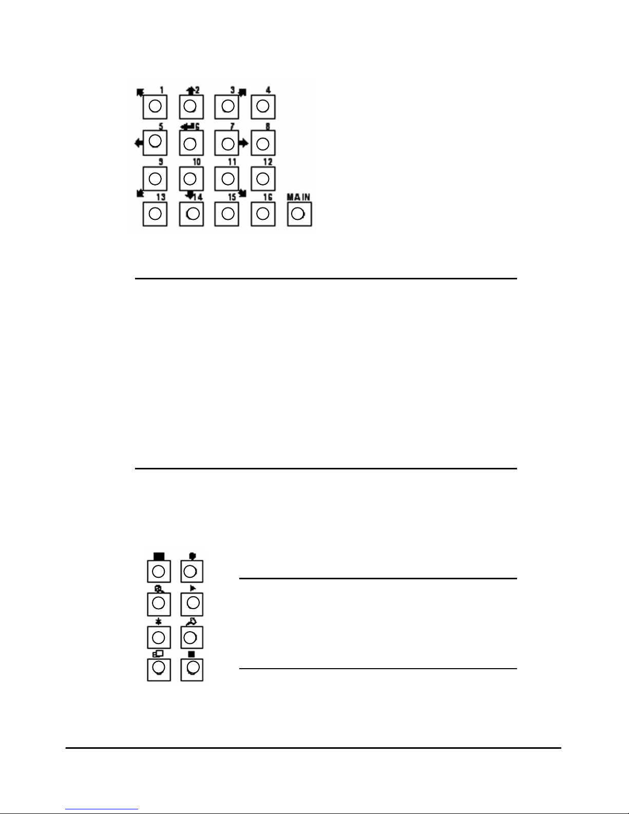
■ Video Channel & Split Button
171615 1413
1211 10
9
87 6
5
43 2 1
Figure 1-2: Video Channel & Split Button
Figure 1-2
1. No.1 Channel (Full Screen), 4A(Split Screen)
2. No.2 Channel (Full Screen), 4B(Split Screen), Up Key
3. No.3 Channel (Full Screen), 4C(Split Screen)
4. No.4 Channel (Full Screen), 4D(Split Screen)
5. No.5 Channel (Full Screen), 9A(Split Screen), Left Key
6. No.6 Channel (Full Screen), 9B(Split Screen), Enter Key
7. No.7 Channel (Full Screen), 5(Split Screen), Right Key
8. No.8 Channel (Full Screen), 8(Split Screen)
9. No.9 Channel (Full Screen), 10(Split Screen)
10. No.10 Channel (Full Screen), 13A(Split Screen), Down Key
11. No.11 Channel (Full Screen), 13B(Split Screen)
12. No.12 Channel (Full Screen), 16(Split Screen)
13. No.13 Channel (Full Screen)
14. No.14 Channel (Full Screen)
15. No.15 Channel (Full Screen)
16. No.16 Channel (Full Screen)
17. Main Window
■ Function Button
8 7
6 5
4
3
2 1
Figure 1-3
1. Display (Full / Split)
2. Emergency Record
3. Zoom
4. Quick Replay
5. Freeze
6. Setup
7. OSD / Sensor
8. Stop (ESC)
Figure 1-3: Function Button
- 8 -
Page 9
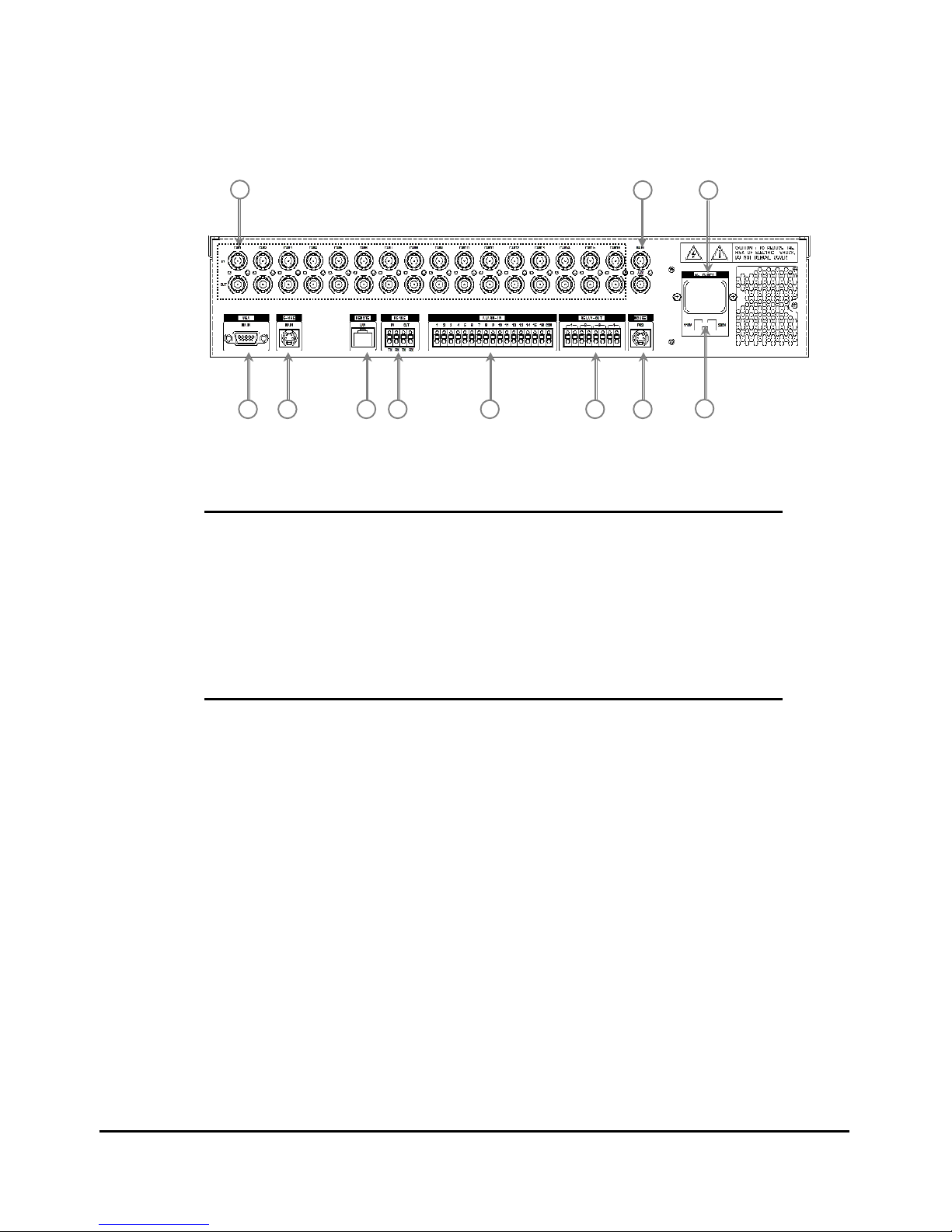
■ Rear Panel
Figure 1-4: Rear Panel
11
10
9876 5 4
3 2
1
Figure 1-4
1. Camera Input & Loop Output
2. Main Monitor
3. Power Input
4. VGA Monitor
5. S-VHS Monitor
6. Ethernet Port
7. RS-485 Port
8. Sensor Alarm Input
9. Control Relay Output
10. Mouse (P/S2)
11. Voltage Selector
■ Camera Connection
1. Camera Input
Connect the cameras to Video Input (BNC connector) on the back of the unit.
2. Loop Output
The Camera or video output is available from the Loop Output on the back of the
unit. When BNC jack is connected to the Video Output, the termination resistance
(75Ω) is automatically switched to impedance status so the external device must
have termination resistance
- 9 -
Page 10
■ Monitor Connection
1. Main Monitor
Connect the monitor to "Main" on the upper part of BNC connector.
2. S-VHS Monitor
Connect the S-VHS monitor to "S-VHS" DIN jack on the rear of the unit.
Output for S-VHS monitor is the same as that of main or auxiliary and has a
separate output buffer and works independently.
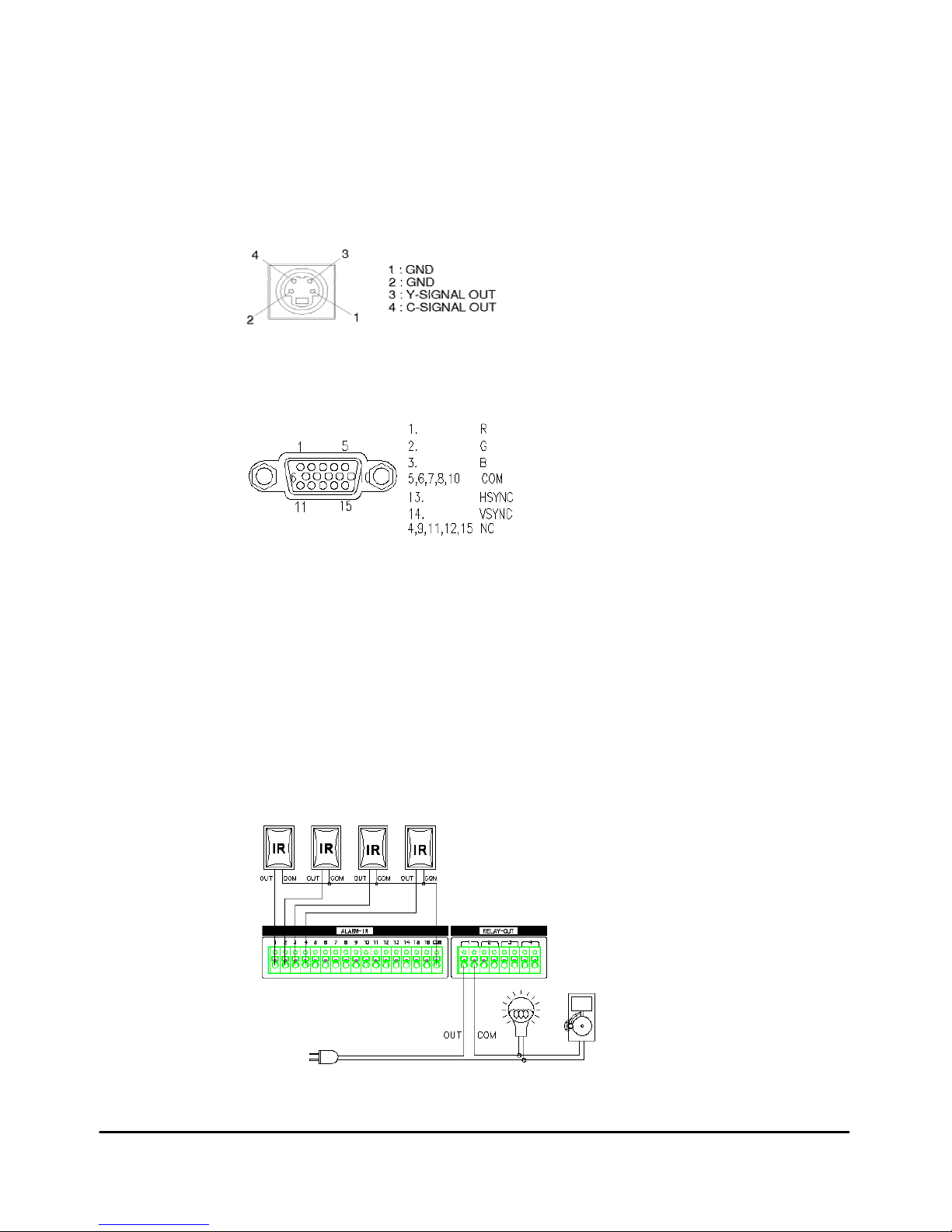
Figure 1-5: S-VHS Connector
3. VGA Monitor
Connect the VGA monitor to DSUB-15 Pin Connector on the rear of the unit.
Figure 1-6: VGA Connector
■ Sensor and Relay Connection
1. Sensor Alarm Input
Connect the sensor to ALARM-IN. The Sensor should be contactor type and
support NO (Normal Open).
2. Control Relay Output
The Output of RELAY-OUT is a relay contactor type and supports NO (Normal
Open), NC (Normal Close). The Output capacity is 220V 1A and a higher capacity
can cause system failure.
Figure 1-7: Sensor and Relay Connector
- 10 -
Page 11
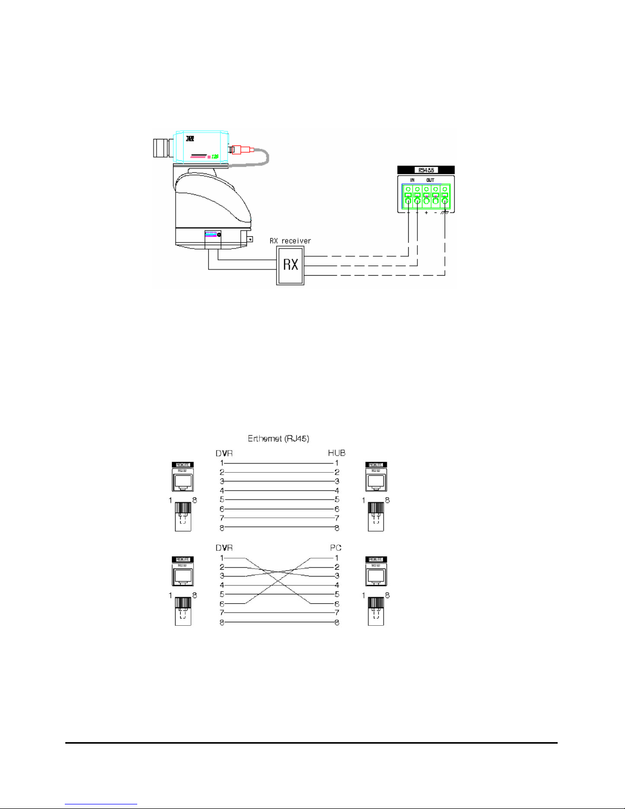
■ RS-485 Connection
Using the RS-485 Terminal Block you can connect to the RS-485 cable up to 1 Km.
Figure 1-8: RS-485 connection for PTZ camera
■ Ethernet Connection
Ethernet connector is a RJ45 type. The maximum cable length is 100m. When you
would like to use a longer cable, you cane use repeater.
Figure 1-9: Ethernet connection
- 11 -
Page 12
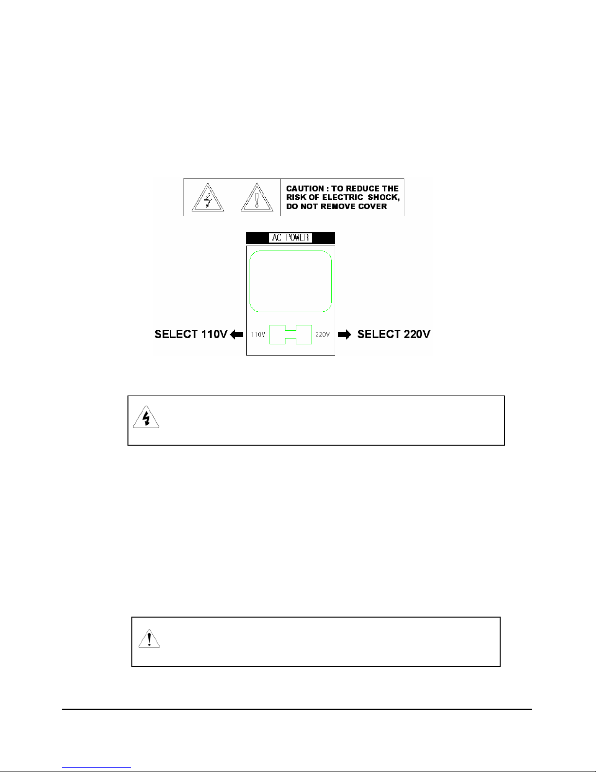
■ Power Cable Connection
Input the power after selecting power voltage of back side of system. Input voltage
tolerance is 10% and we can not warranty if you are using the over tolerance around
10%. If the electric system is not stable, please using the UPS or AVR.
Standard Input voltage: AC110V 50/60Hz or AC220V 50/60Hz
Figure 1-10: Input power selection
CAUTION: FACTORY DEFAULT SETTING IS AC110V 50/60Hz IN POWER
SELECT SWITCH. PLEASE DOUBLE CHECK BEFORE YOU INPUT
THE POWER INTO THE SYSTEM.
■ PAL / NTSC Selection
PAL or NTSC is set at the factory according to the country where the system is
shipped. If necessary, it can be reset as follows;
• Turn off the system, and then remove the cover.
• Reset the PAL/NTSC selection jumper (NTSC: open, PAL: close). Please refer
to Figure 4-1.
• Reassemble the cover.
• Turn on the system and format the HDD.
NOTE: WHEN THIS SETTING IS CHANGED, YOU WILL LOSE ALL OF YOUR
RECORDED DATA AND SETTINGS.
YOU SHOULD SET THE SYSTEM AGAIN AFTER THIS PROCEDURE.
- 12 -
Page 13

Chapter
2
Operation Mode
■ General Information
■ Power On/Off
■ Display Screen
■ System Status
■ PTZ Control
■ How to Record
■ How to Replay
■ How to Backup
- 13 -
Page 14

2.1 General Information
You can operate all functions of the system by use of the 26 buttons located on the front
panel and a mouse. Also you can remotely control this unit via RS-485 or the Ethernet
port located on the backside.
System status is indicated by either LED light on the operator buttons or the monitor.
The system is protected from any inadvertent pressing of any operator buttons. But care
should be taken when using the functions of HDD Formatting as then can lead to data
loss. To avoid any mistake, the re-confirmation is required when these functions are
selected.
2.2 Power On/Off
▪ Power On: Push the “POWER” button in the front panel for 5 seconds.
▪ Power Off: Push the “POWER” button in the front panel for 5 seconds or click the
mouse’s right button on the power off screen.
Figure 2-1: Power off
- 14 -
Page 15
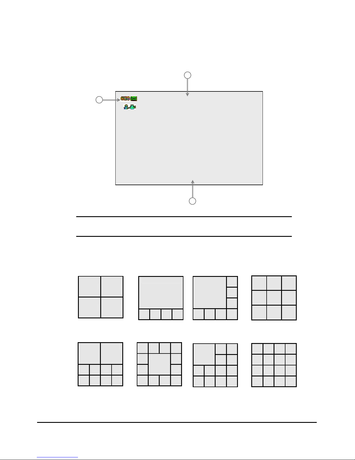
2.3 Display Screen
■ Camera View
Figure 2-2: Full screen
2
22000055//0011//0011 2200::2255::4433
CCAAMM 0011
3
1
Figure 2-2
1. Status Icon: Record, Backup, Motion or Freeze, Sensor
2. Camera Name
3. Current Time
■ Screen Division
4A~4D Split screen 5 Split screen 8 Split screen 9 Split screen
10 Split screen 13A Split screen 13B Split screen 16 Split screen
- 15 -
Page 16
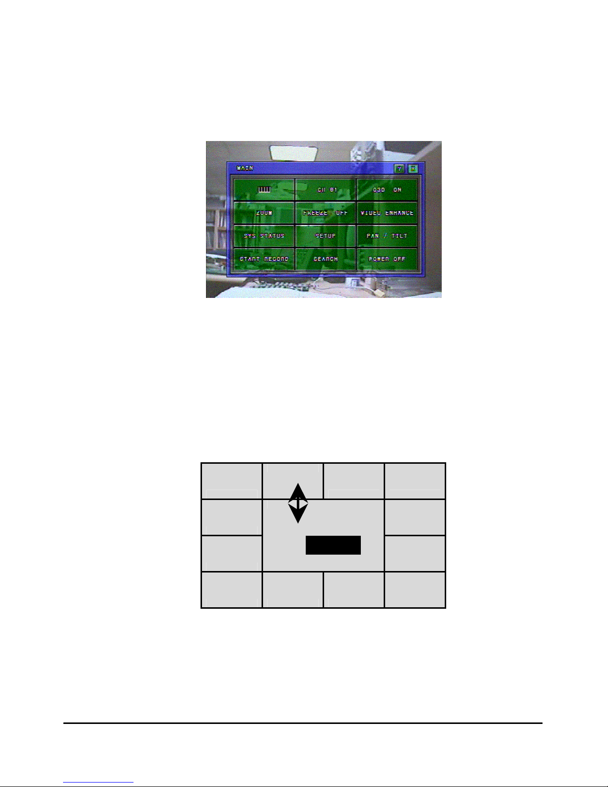
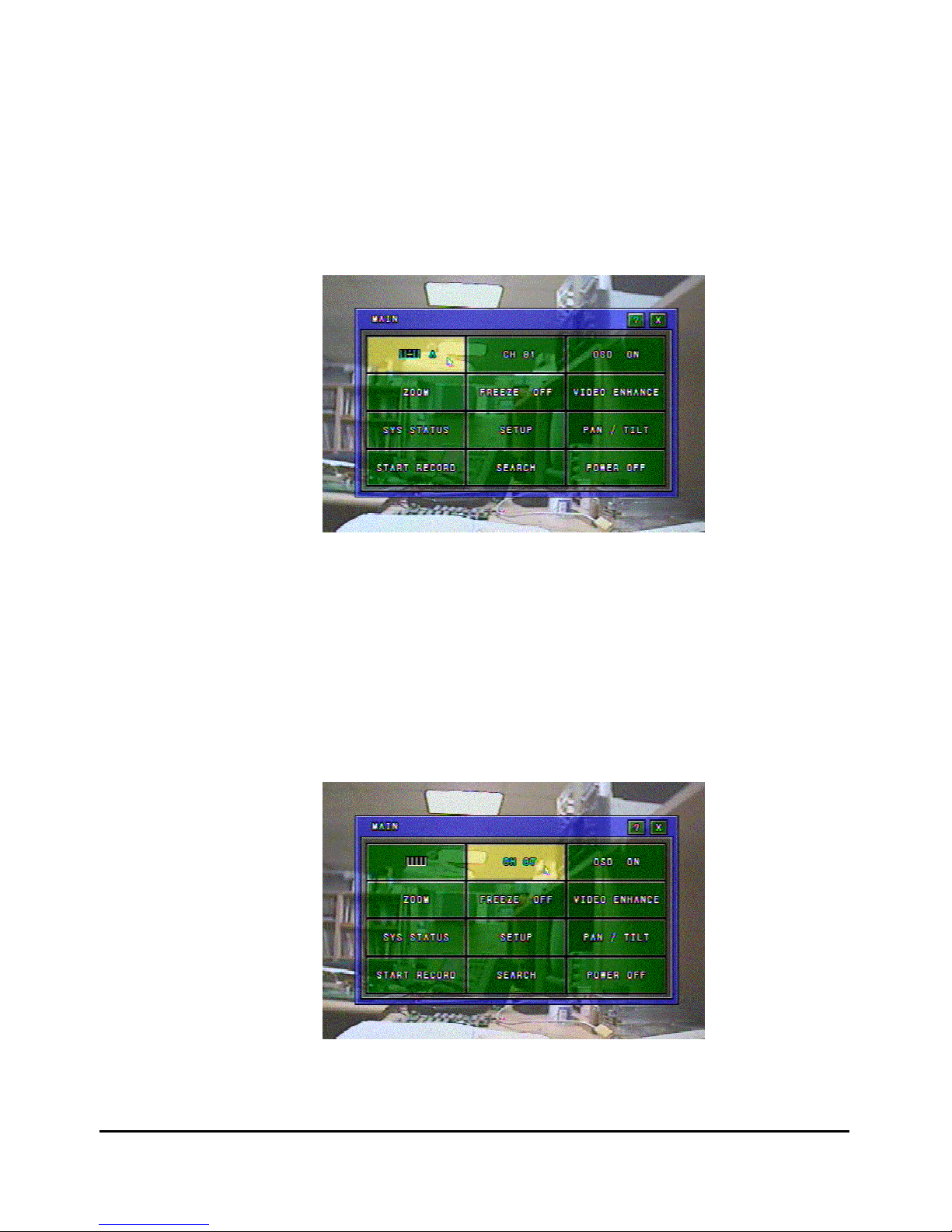
■ Live Main Window
▪ Press the “MAIN” button or Click the mouse’s right button on the live screen.
▪ It will show the Live Main Window.
▪ Click the “EXIT” button, and it will return to the Live Screen.
Figure 2-3: Live Main Window
■ Switching a Specific Screen
By clicking one screen and drag & drop to another screen, you can switch a specific
screen on the Live Screen. This Window is always occupied this position also in replay
mode. The following example shows that #2 camera and #6 camera screens are switched
each other.
C1
C2
C3 C4
C5 C7
C8
C6
C9
C10 C11 C12 C13
2 <=> 6
Figure 2-4: Switching a specific screen
- 16 -
Page 17
■ Split Screen
▪ Split screen is possible in the LIVE mode or RECORD mode.
▪ Click the “SPLIT” button, and choose the desired split screen with the mouse’s wheel or
“UP/DOWN” button. To complete the setting and close the Live Main Window, click the
“SPLIT” button again. It will show the Live Main Window.
▪ It is available to change into various SPLIT modes with buttons on the front panel. To
change into SPLIT mode, Press the “Display” Key on the front panel.
Figure 2-5: Changing a split screen
■ Full Screen
▪ Full screen is possible in the LIVE mode or RECORD mode.
▪ Click the “FULL” button, and choose the desired full channel with the mouse’s wheel or
“UP/DOWN” Keys. To complete the setting and close the Live Main Window, click the
“FULL” button again.
Figure 2-6: Full screen
- 17 -
Page 18
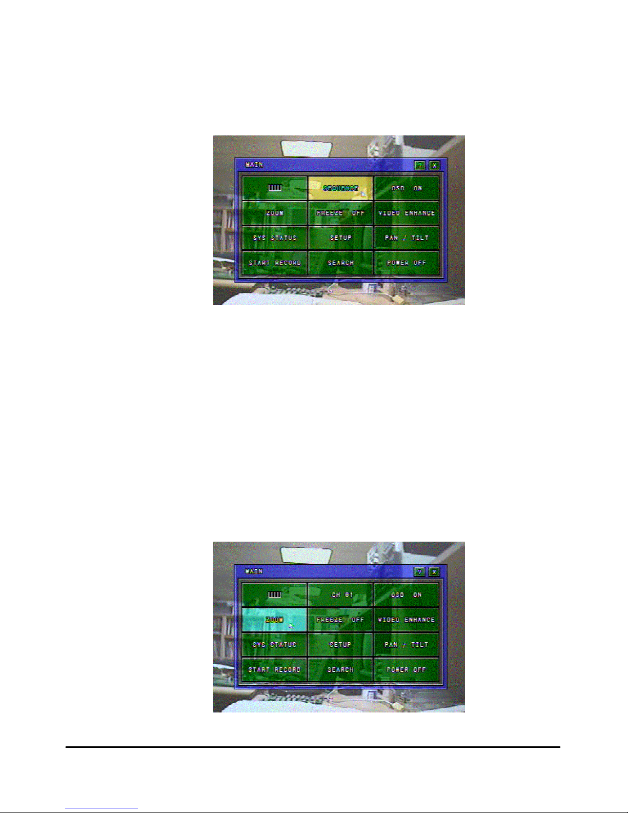
■ Sequential Screen
▪ Sequential screen is possible in the LIVE mode or RECORD mode.
▪ Display each channel in turn after setting auto switching of video input channel.
▪ To display the sequential screen and close the LIVE MAIN Window, press the
“SEQUENCE” button again.
Figure 2-7: Sequential screen
■ OSD(On Screen Display) On/Off
▪ OSD On/Off is possible in the LIVE mode or RECORD mode.
▪ When the “OSD” button is clicked, Live Main Window is closed and all the texts except
for the video display are deleted temporarily.
▪ When the button is clicked again while OSD is in OFF position, the system status will be
the normal condition. It is available to use pressing the “OSD” button on the front panel.
■ Zooming Screen
▪ Zooming screen is possible in the LIVE mode or RECORD mode. This function is
available in the full screen mode only.
▪ It is available to zoom 1x~4x. To display the zoom screen and close the Live Main
Window, click the “ZOOM” or press the “ZOOM” button on the front panel.
▪ To complete zoom mode, click the mouse’s right button on the zoom screen, and then
click the “ZOOM” or press the “ZOOM” button on the front panel.
Figure 2-8: Zoom button
- 18 -
Page 19
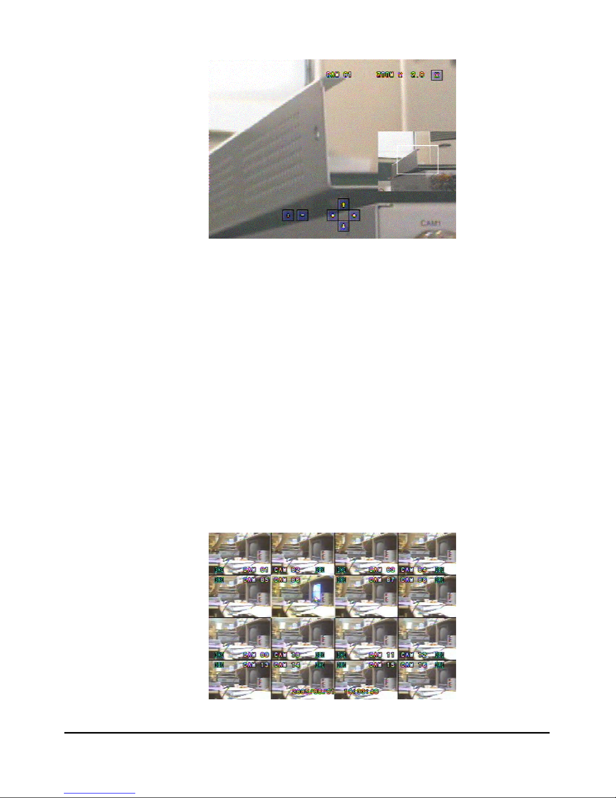
Figure 2-9: Zooming screen
▪ ZOOM IN: Click the ‘+’ button or Press “UP/DOWN/LEFT/RIGHT” button on the front
panel.
▪ ZOOM OUT: Click the ‘-’ button or Press “UP/DOWN/LEFT/RIGHT” button on the front
panel.
▪ MOVE: Click the ‘Arrow’ button or press UP/DOWN/LEFT/RIGHT” button on the Front
panel to move each direction of Zoom screen.
▪ PIP On/Off: Click the mouse’s left button in part of not PIP screen or press the “ENTER”
button on the front panel.
▪ OSD On/Off: If you click the mouse left button when you are not using the PIP Window,
or “ESC” button on the front panel, OSD will On/Off.
■ Freeze
▪ Freeze is possible in the LIVE mode or RECORD mode. This function is available in the
full screen mode only.
▪ To display the Freeze mode, click the “FREEZE” button on the Live Main Window or
press the “FREEZE” button on the front panel.
▪ To complete the Freeze mode, click the “FREEZE” button again on the Live Main
Window or press the “FREEZE” button on the front panel again.
▪ Freeze On/Off: Click the mouse’s left button or press the “ENTER” button on the front
panel.
Figure 2-10: Freeze screen
- 19 -
Page 20
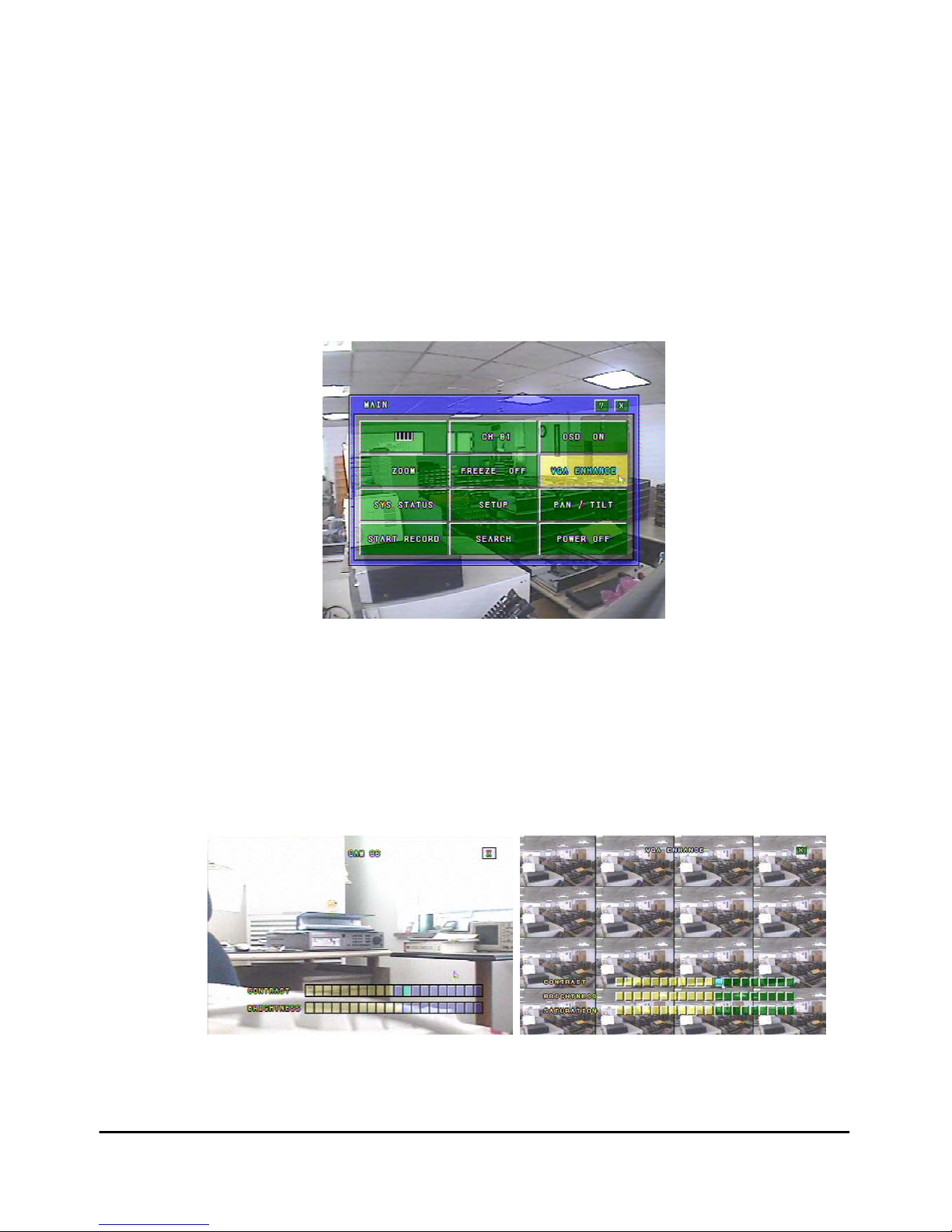
■ Camera/VGA Enhance
▪ Click the “CAM/VGA ENHANCE” button on the Live Main Window, and then select the
Camera enhance or VGA enhance by using mouse’s wheel or “UP/DOWN” button on
the front panel.
▪ Select the channel to set Contrast / Brightness for camera or Contrast / Brightness /
Saturation for VGA by using the mouse or the “UP/ DOWN/LEFT/RIGHT” button on the
front panel.
▪ It will show the camera / VGA control Window when you click the mouse’s right button or
the “ENTER” button on the front panel.
▪ To return to the LIVE MAIN Window, click the mouse’s right button or press the “ESC”
button on the front panel.
Figure 2-11: Video enhance button
▪ Click the Contrast / Brightness / Saturation Bar button with mouse’s left button or
“ENTER” button on the front panel. The color of bar is indicated in yellow and the
setting value of video is changed.
▪ Click the (EXIT) button, and it will show the channel selection Window. Click the mouse’s
right button or “ESC” button on the front panel, it will show Live Main Window.
Figure 2-12: Contrast / Bright / Saturation control
- 20 -
Page 21

2.4 System Status
▪ Click the “SYS STATUS” button on the Live Main Window, and it will show the SYSTEM
STATUS Window. Click the “EXIT (X)” button to return to the Live Main Window.
Figure 2-13: System Status button
▪ System Status Window indicates a several options such as value of MAC address, IP
address, Port number and the quantity of used HDD.
Figure 2-14: System Status menu
- 21 -
Page 22

▪ Click the “VIDEO LOSS LISTS” button on the SYSTEM STATUS Window, and it will
show the Video Loss Lists Window.
▪ Video Loss Lists indicate the Video Loss channel and time when the video is not
inputted.
▪ It is able to indicate on unit of page in order with “UP/DOWN” button on the front panel
or mouse’s wheel.
Figure 2-15: Video Loss lists
▪ Click the “CLEAR LISTS” button or press the “ENTER” button on the front panel, and it
show the message Window of which ask the clear or not.
▪ Click the “OK” button to clear Video Loss Lists.
▪ Click the “CANCEL” button to cancel the working.
Figure 2-16: Clear lists
▪ Power Loss Lists indicate the time when DVR is Power Off.
▪ To know the searching and operating Power Loss Lists, refer to the Video Loss Lists.
- 22 -
Page 23
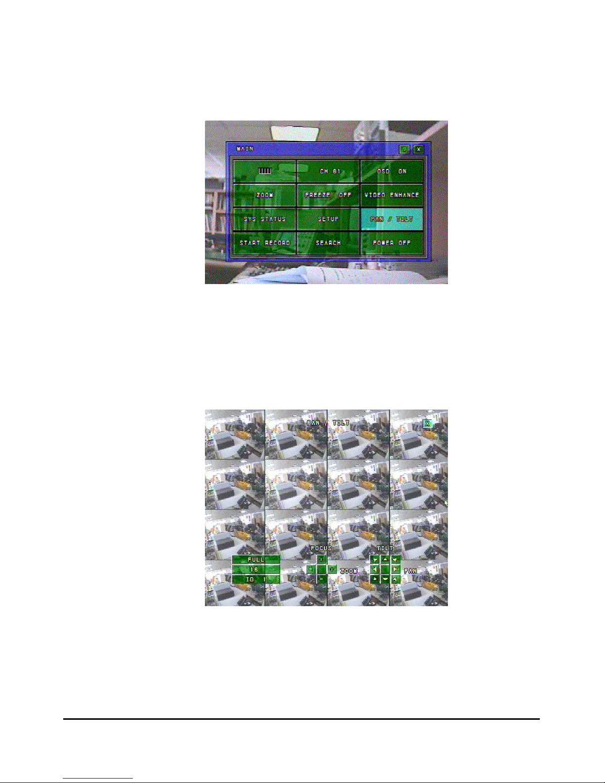
2.5 PTZ Control
▪ Click the “PAN/TILT” button on the Live Main Window, and it will show the PAN/TILT
Window. Click the “EXIT (X)” button to return to the Live Main Window.
Figure 2-17: PAN/TILT button
■ Full/Split/ID
▪ Select the Full/Split/ID button with the mouse or “UP/LEFT/ RIGHT/DOWN” button on
the front panel, and then press the mouse’s left button or “ENTER” button on the front
panel.
▪ To complete the setting, click the Full/Split/CH button again after select the value with
mouse’s wheel or “UP/DOWN” button on the front panel.
Figure 2-18: PAN/TILT screen
■ Pan/Tilt/Zoom/Focus
▪ You can control Pan, Tilt, Zoom and Focus of the PTZ camera.
▪ Using the mouse click the left button on the each button.
▪ Using the front panel button click the “DISPLAY” button, and then select ZOOM/FOCUS
button, and then control using the “UP / DOWN / LEFT / RIGHT” button.
- 23 -
Page 24
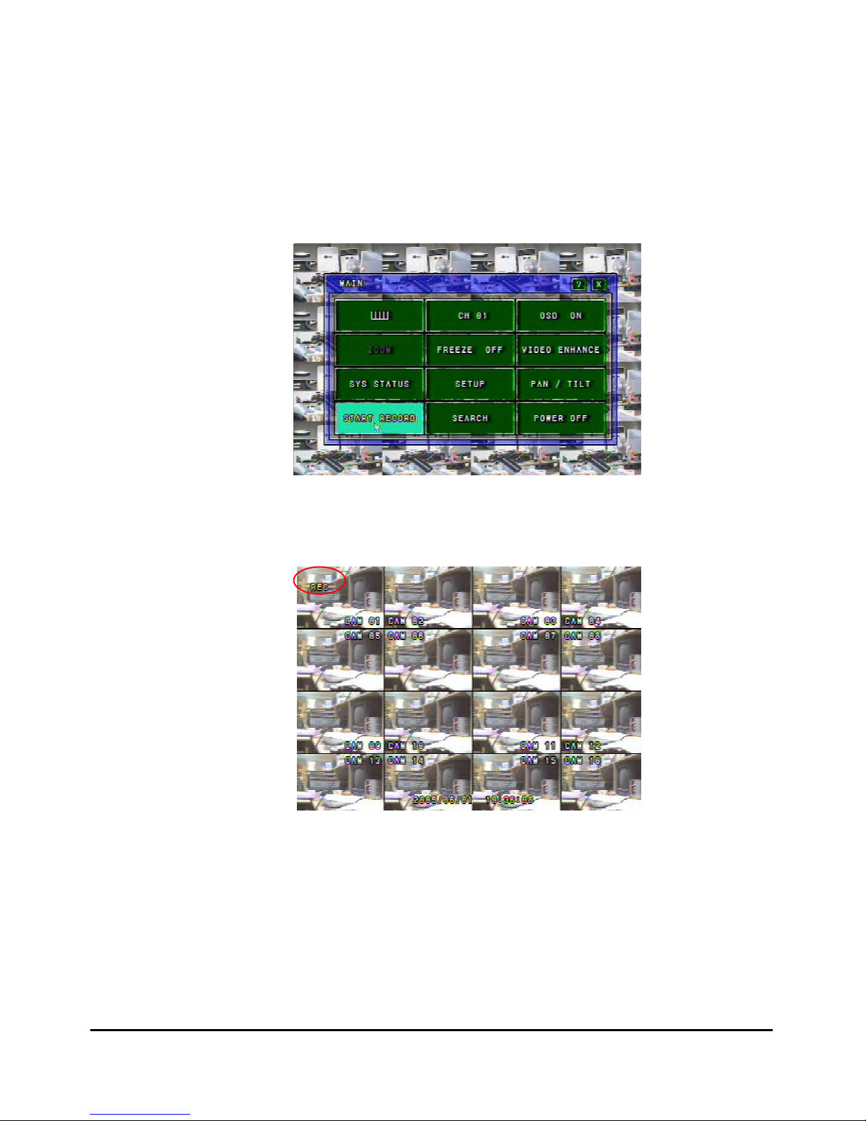
2.6 How to Record
▪ You need to select a recording mode on RECORD CONFIG in advance.
▪ There are several recording options such as Manual Always Recording, Motion or
Sensor Event Recording, Time & Day Schedule Recording.
▪ To start recording, click the “START RECOD” button on the Live Main Window.
Figure 2-19: Start Record button
Figure 2-20: Recording Status on Live Screen
- 24 -
Page 25

2.7 How to Replay
▪ To replay the recorded data, click the “SEARCH” button on the Live Main Window, and it
will show the SEARCH Window. Click the “EXIT (X)” button to return to the Live Main
Window.
Figure 2-21: Search menu
■ Search Path
▪ Select the one of storage device among “Record HDD”, “Backup HDD” or “Backup USB”
to replay.
Figure 2-22: Search Path
■ Lists Sort
▪ Select the one of the list sorted such as “Emergency / Manual / Timer / Sensor / Motion”.
To show the all list, click the “ALL” button.
[ALL] [Emergency] [Manual] [Timer] [Sensor] [Motion]
Figure 2-23: List Buttons
▪ If there is no replay list, “NONE RECORD LISTS” is shown. To replay the all list, click
“TOTAL” button.
▪ Click the one of list button such as “0001, 0002”, and it will show the RECORD PLAY
Window.
- 25 -
Page 26

■ Searching Time
▪ Select the searching time with the mouse or “UP/DOWN” button on the front panel.
Figure 2-24: Record Play Window
▪ By clicking the “BAR” button under the menu of searching time, you can easily select the
searching time from 1 to 10 stage of total recorded time.
Figure 2-25: Searching Time button
■ Replay Camera Selection
▪ Select the one of 16 cameras, or click ”A” button to select all cameras.
Figure 2-26: Replay Camera Selection
- 26 -
Page 27

■ Start Replay
▪ Click the “REPLAY” button to replay the recorded data, and you can control replay
speed 1 to 64 times.
Figure 2-27: Start Replay buttons
■ Replay Control Buttons
Figure 2-28: Replay Control buttons
▪ Pause Button
To pause replaying, click the
▶▌▌button or use the key Jog.
▪ REW / FF Button
During the replaying, click the
◀ or ▶ button or use key Shuttle for rewinding and
forwarding.
Press the “
+” or “-“ button to accelerate the speed up to 64 times. (Same as shuttle)
▪ Frame by Frame
In the pauses of the replay, click the
◀ button to view previous frame in still image and
press the
▶button to view the next frame in still image.
■ Single Screen Replay
▪ When a section of 16 split screen is clicked, the selected screen is displayed in s single
screen. Clicking again brings back to its previous split screen.
Figure 2-29: Single Screen Replay
- 27 -
Page 28

■ OSD(On Screen Display) On/Off
▪ OSD On/Off is possible in the LIVE mode or RECORD mode.
▪ When the “OSD” button is clicked, all the texts except for the video display are deleted
temporarily.
▪ When the button is clicked again while OSD is in OFF position, replaying screen will be
the normal condition. It is available to use pressing the “OSD” button on the front panel.
Figure 2-30: OSD OFF screen
■ Zooming Screen
▪ Zooming screen is possible in the LIVE mode or RECORD mode. This function is
available in the full screen mode only.
▪ It is available to zoom 1x~4x. To display the zoom screen and close the Live Main
Window, click the “ZOOM” or press the “ZOOM” button on the front panel.
▪ To complete zoom mode, click the mouse’s right button on the zoom screen, and then
click the “ZOOM” or press the “ZOOM” button on the front panel.
Figure 2-31: Zooming screen
- 28 -
Page 29

2.8 How to Backup
▪ Backup function is only available on condition that the search path is set to “Record
HDD”.
▪ In the SEARCH Window, select the backup list by clicking button. Once this
button selected, it change to the checked sign button. This button is toggled.
▪ You can select a multiple backup list on the replay lists. But it can not be exceeded
backup HDD space compare with total capacity of backup lists.
Figure 2-32: Backup list selection
■ Backup Start/End Time
▪ During replaying, select the backup start time by clicking button.
Once this button selected, it change to the checked sign button.
▪ Finished searching backup picture, select the backup end time by clicking
button. Once this button selected, it change to the checked sign button.
Figure 2-33: Backup start & end time setting
- 29 -
Page 30

■ Backup USB Format
▪ Plug in USB stick memory on the front panel.
▪ When the USB memory is plugged into the system, the “GO TO BACKUP” button is
activated and USB port LED is lighting on the front panel.
▪ Click the “GO TO BACKUP” button or press a direction control key on the front panel,
and it will show the BACKUP DIALOG screen.
Figure 2-34: Backup Dialog button
▪ Click the “USB” button, and it will show the USB format Window.
▪ To start format click the “OK” button.
▪ To cancel, click the “CANCEL” button.
▪ To back up, click the “START” button.
Figure 2-35: Backup Dialog Window
- 30 -
Page 31

■ Backup HDD Format
▪ To format the BACKUP HDD, you have to enable the backup HDD in System
Configuration Window.
▪ Enter the Setup Window, select “SYSTEM” menu, and then select the “BACKUP DISK”.
▪ By using mouse’s wheel or “UP/DOWN” button on the front panel, set the backup disk to
“ENABLE”. Click “STOP RECORD” in the MAIN menu before setting the back up.
Figure 2-36: Backup Disk setting
▪ After you make backup disk to be enable, enter the Setup Window, select “DISK
MANAGER” menu, and then click the “HDD” button.
▪ If the backup HDD is not installed in your system, it indicates “UNINSTALLED” on the
DISK MANAGER Window.
Figure 2-37: Uninstalled Backup HDD
- 31 -
Page 32

▪ If the backup HDD is installed for the first time in your system, it indicates
“UNFORMATTED” on the DISK MANAGER Window.
Figure 2-38: Unformatted Backup HDD
▪ Click the “HDD” button, and it will show the check message for HDD format.
▪ Click the “OK” button, and you can see formatting process of the HDD.
▪ Click the “CANCEL” button to return to the DISK MANAGER Window.
Figure 2-39: HDD format dialog
- 32 -
Page 33

■ Starting Backup
▪ Select the backup disk, and then click “BACKUP START” button.
Figure 2-40: Backup disk selection
▪ The backup icon will show on the left upper corner of the Live Screen.
▪ If the backup disk is selected as USB disk, the backup USB LED is twinkling during the
backup process
Figure 2-41: Backup process icon
■ Forced Stop Backup
▪ To stop backup forcibly, go to Live Main Window, and then click “SEARCH” button.
▪ Click “OK” button to stop the process of backup.
Figure 2-42: Backup process icon
■ Replay the backup data in PC
▪ You can replay the backup data in PC, and make convert .AVI format for direct play on
Window Media Player. The Host software in CD contains this function.
- 33 -
Page 34

- 34 -
Chapter
3
Setup Mode
■ Setup Window
■ System
■ Time / Date
■ Disk Manager
■ Camera
■ Record Configuration
■ Motion Configuration
■ Sensor Configuration
■ Network Configuration
■ Pan/Tilt Configuration
■ System Information
■ Color Setting
Page 35

3.1 Setup Window
▪ Press the “MAIN” button or Click the mouse’s right button on the live screen, and it will
show the Live Main Window.
▪ Click the “SETUP” button, and it will show the Setup Window.
▪ Click the “EXIT” button, and it will return to the Live Main Window.
Figure 3-1: Setup Window
3.2 System
▪ Click the “SYSTEM” button, it will show the System Setup Window.
▪ Click the “EXIT” button on the System Window, it will return to the Setup Window.
Figure 3-2: System Setup Window
- 35 -
Page 36

■ Language
▪ You can select one of Language such as English, Japanese, Chinese and Korean.
▪ Select one of Language by using the mouse’s wheel or pressing the “UP/DOWN” key on
the front panel.
▪ After selection, click the “LANGUAGE” button again for confirmation.
Figure 3-3: Language Selection
▪ Click the “OK” button to change to the selected language, and then all of window will
close and back to the Live Screen.
▪ Click the “CANCEL” button to cancel the language setting.
Figure 3-4: Change Language Window
■ Backup Disk Enable / Disable
▪ Click “STOP RECORD” in the MAIN menu before setting the backup disk.
▪ It defines Backup HDD disk.
▪ Enable: Removable HDD is assigned for the Backup Disk.
▪ Disable: Removable HDD is assigned for the Internal Fixed Disk.
Figure 3-5: Backup Disk Enable / Disable
- 36 -
Page 37

■ Mouse Sensitivity
▪ It enables you to set the mouse sensitivity. It has parameter 1 to 4.
▪ Take a few second for the mouse initialize with changed parameter.
Figure 3-6: Mouse Sensitivity Setting
■ Record Resolution
▪ Click “STOP RECORD” in the MAIN menu before setting the Record Resolution.
▪ It enables you to set the recording size. You can select the recording resolution both of
“720x480” and “320x240” size.
▪ Click the “RECORD RESOLUTION” button, and select the recording size by using the
mouse wheel or “UP/DOWN” key on the front panel.
▪ After selection, click the “RECORD RESOLUTION” button again for confirmation.
Figure 3-7: Recording Resolution Setting
■ Factory Default
▪ Click “STOP RECORD” in the MAIN menu before setting the Factory Default.
▪ Click the “FACTORY DEFAULT” button, it will show the Factory Default Window.
Figure 3-8: Factory Default Setting
▪ Click the “OK” button, starts running the Factory Default and reboots the system.
▪ Click the “CANCEL” button to return to the System Setup Window.
Figure 3-9: Factory Default Window
- 37 -
Page 38

■ Firmware Update
THIS SECTION IS NOT FOR USERS, ONLY FOR MANUFACTURER
AND DISTRIBUTION CENTER.
[Update by LAN connection]
▪ If you want firmware update by using LAN connection, you should select “LAN ENABLE”.
▪ For more details, please refer to the Chapter 5 “Remote Host Software”.
Figure 3-10: Firmware update via LAN
[Update by USB device]
▪ Save the firmware onto USB device by using Remote Host Software, and then insert
USB device into DVR.
▪ Click the “USB START” button, and then the “OK” button to start firmware update.
▪ During firmware updating, mouse and front key will not be worked.
▪ When firmware update is finished, DVR will reboot.
Figure 3-11: Firmware update by USB device
NOTE: FIRMWARE UPDATE USING USB DEVICE IS NOT AVALIBLE WHEN
THE DVR IS ON RECORD, REPLAY, BACKUP OR REMOTE HOST
CONNECTION.
■ User Authorization
▪ It enables you to set the user authorization.
▪ Click the “ADMIN” button, it will show the Admin Dialog Window.
Figure 3-12: Admin Dialog Window
- 38 -
Page 39

[User ID Setting]
▪ Click the “USER ID” button, it will show On Screen Keyboard.
▪ Enter the user ID by using On Screen Keyboard, and then click “OK” button to set the
new user ID.
▪ Click the “CANCEL” button to return to the user ID setting.
Figure 3-13: User ID Setting
[Password Setting]
▪ ON/OFF: It enables you that the DVR main function should be controlled by only
authority people.
▪ When you set for ON, it needs the password to control Setup, Reply and Record.
▪ PASSWORD: Click the password “********” button. You can enter 8 digit password by
using On Screen Keyboard and also you need to enter all of 8 digit password for DVR
operation.
▪ Click “OK” button to set the user’s password.
Figure 3-13-1: Password Setting
[Network Password Setting]
▪ This setting procedure is the same as password setting.
▪ ON/OFF: It enables you that the connection DVR via network should be controlled by
only authority people.
▪ When you set for ON, it needs the password to connect to the DVR via network.
- 39 -
Page 40

3.3 Time / Date
▪ Click the “TIME / DATE” button on the Setup Window, it will show the Time / Date Setup
Window.
▪ Click the “EXIT” button on the Time / Date Setup Window, it will return to the Setup
Window.
Figure 3-14: Time/Date Setup Window
■ Time Format
▪ Click the “TIME FORMAT” button, and then change the Time Format by using the mouse
wheel or “UP/DOWN” key on the front panel.
▪ Time Format is selectable by 12 hour or 24 hour mode.
Figure 3-15: Time Format
■ Time Setting
▪ Click “STOP RECORD” in the MAIN menu before setting the Time.
▪ Click the “Hour” button, and then set the Hour by using the mouse wheel or
“UP/DOWN” key on the front panel. After setting the Hour, click the “Hour” button again
for confirmation.
▪ How to set the “Minute” and “Second” are the same as above.
Figure 3-16: Time Setting
- 40 -
Page 41

■ Date Format
▪ Click the “DATE FORMAT” button, and then set the Date Format by using the mouse
wheel or “UP/DOWN” key on the front panel.
▪ It has three type of Date Format such as YYYY/MM/DD, DD/MM/YYYY, MM/DD/YYYY.
Figure 3-17: Date Format
■ Date Setting
▪ Click “STOP RECORD” in the MAIN menu before setting the Date Setting.
▪ Click the “Year” button, and then set the Year by using the mouse wheel or “UP/DOWN”
key on the front panel. After setting the Year, click the “Year” button again for
confirmation.
▪ How to set the “Month” and “Day” are the same as above.
Figure 3-18: Date Setting
■ Display
▪ It enables you to display date & time on the Live Screen.
▪ Click the “DISPLAY” button to set display on or off.
Figure 3-19: Display On/Off Setting
NOTE: SETTING THE NEW TIME CAUSE OF THE RECORDING DATA LOSE,
THEREFORE BE CAREFUL WHEN YOU SET THE TIME
AFTER SETTING THE TIME, HDD SHOULD BE FORMATTED
BEFORE START RECORDING.
- 41 -
Page 42

3.4 Disk Manager
▪ Click the “Disk Manager” button on the Setup Window, it will show the Disk Manager
Setup Window.
▪ Click the “EXIT” button on the Disk Manager Window, it will return to the Setup Window.
▪ Total 4 HDDs can be installed and disk information will display automatically on the
window after connected.
▪ Without HDD, recording is not available but other functions can be used.
Figure 3-20: Disk Manager Window
■ HDD Formatting
▪ Click “STOP RECORD” in the MAIN menu before formatting the HDDs.
▪ Click the installed HDD button, it will show the check message for HDD formatting.
▪ Click the “OK” button, and you can see formatting process of the HDD.
▪ Finished formatting, it will close the formatting process Window.
▪ Click the “CANCEL” button to return to the DISK MANAGER Window.
Figure 3-21: HDD format dialog
- 42 -
Page 43

3.5 Camera
▪ Click the “CAMERA” button on the Setup Window, it will show the Camera Setup
Window.
▪ Click the “EXIT” button on the Camera Setup Window, it will return to the Setup Window.
Figure 3-22: Camera Setup Window
■ Camera On/Off
▪ Click “STOP RECORD” in the MAIN menu before setting the camera on/off.
▪ It enables you to on/off the camera input.
▪ If you select “OFF”, it will not display the video on the Live Screen.
▪ You can select “ON” or “OFF” by using the mouse wheel or “UP/DOWN” key on the
front panel.
▪ To set the all of video “ON” or “OFF”, click the “A” button.
Figure 3-23: Camera On/Off Setting
■ Buzzer On/Off
▪ It enables you to beep the buzzer when the video lost.
▪ To set the all of buzzer “ON” or “OFF”, click the “A” button.
Figure 3-24: Buzzer On/Off Setting
- 43 -
Page 44

■ Relay-out On/Off
▪ It enables you to activate relay-out when the video lost.
▪ There are six types of relay-out such as “X (off)”, “1”, “2”, “3”, “4”, “A”.
▪ You can select “ON” or “OFF” by using the mouse wheel or “UP/DOWN” key on the front
panel.
▪ To set the all of relay-out “ON” or “OFF”, click the “A” button.
Figure 3-25: Relay-out On/Off Setting
■ Display
▪ It enables you to display the camera’s title on the Live Screen.
▪ You can select “ON” or “OFF” by mouse clicking or “UP/DOWN” key on the front panel.
Figure 3-26: Name Display On/Off Setting
■ Camera Title
▪ Click the “CAMERA TITLE” button on the Camera Setup Window, it will show the
Camera Title Setup Window.
▪ Click the “CAM” button, it will show On Screen Keyboard.
▪ Enter the camera’s title by using On Screen Keyboard, and then click “OK” button to
display camera’s title on the Live Screen.
▪ Click the “CANCEL” button to return to the origin name.
Figure 3-27: Camera Title Setting
■ Auto Switching (Sequence Display)
▪ Using the Camera Sequence mode, you can set the sequence dwell time up to 9sec.
▪ Click the “SEQUENCE DWELL TIME” button, and then change the Dwell Time by using
the mouse wheel or “UP/DOWN” key on the front panel.
Figure 3-27-1: Sequencing Dwell Time Setting
- 44 -
Page 45

3.6 Record Configuration
▪ Click “STOP RECORD” in the MAIN menu before setting the Record Configuration.
▪ Click the “RECORD CFG” button on the Setup Window, it will show the Record
Configuration Window.
▪ Click the “EXIT” button on the Record Configuration Window, it will return to the Setup
Window.
Figure 3-28: Record Configuration Window
NOTE: RECORDING CONFIGURATION IS ONLY AVAILABLE IN THE “STOP
RECORD” MODE. IF THE SYSTEM IS ON “RECORDING MODE”, YOU
SHOULD CHANGE TO “STOP RECORD” FOR RECORDING
CONFIGURATION.
■ Emergency Record Mode Setting
▪ By pressing the “Emergency Record” button (Figure 1-3: Function Button ②) the front
panel, you can record instantly.
Figure 3-29: Emergency Record Mode Setting
[Quality]
▪ It enables you to set the recorded image quality on Emergency Record mode.
▪ It is selectable from 1 to 30 grades.
[Camera Set]
▪ It enables you to set the recording frame rate for each camera on Emergency Record
mode.
- 45 -
Page 46

■ Manual Record Mode Setting
▪ In the Manual Record Mode, the recording works only by user’s operation.
Figure 3-30: Manual Record Mode Setting
[Quality Setting]
▪ Click the “QUALITY” button, you can see the live image and recording image at the
same time on the split window. So you can easy to set the recording frame and the
recorded image quality on the Quality Setting Window.
▪ The Quality Setting Window have two split windows. One is the live image window and
the other is after recording image window. So you can compare Live Image with
Playback Image when you set the image quality (selectable from 1 to 30 grades).
▪ After you set the recording frame and image quality, you can see the estimated
recording time according to setting level and installed HDD size.
Figure 3-31: Quality Setting Window
- 46 -
Page 47

[Cam Set]
▪ It enables you to set the recording speed of each camera.
▪ Click the “CAM SET” button on the Record Configuration Window, it will show the
Recording Speed Setup Window.
Figure 3-32: Recording Speed Setting
Figure 3-32
1. All Enable/Disable – Allows you to select recording enable or disable for all
cameras.
2. All Max Speed – Allows you to set the max. recording speed for all cameras.
3. Total Speed – Displays the total recording speed.
4. Each Camera setting – Allows you to set the recording speed for each camera.
[Individual Recording Speed Setting]
▪ You can select the recording speed for each camera.
▪ Click the one of camera setting button, and then select the recording frame by using the
mouse or pressing the “UP/DOWN” key.
▪ Click the “EXIT button, it will return to the Record Configuration Window.
Figure 3-33: Individual Recording Speed Setting
- 47 -
Page 48

▪ The Equal recording speed for all cameras
720 x 240 320 x 240
NTSC PAL NTSC PA L
Total Each Total Each Total Each Total Each
60 3.75 50 3.12 120 7.50 100 6.25
30 1.87 25 1.56 60 3.75 50 3.12
15 0.93 12.5 0.78 30 1.87 25 1.56
▪ The recording speed for each camera
NTSC PAL
0.50 0.50
1.00 1.00
2.00 2.50
5.00 5.00
7.50 6.25
10.00 8.33
15.00 12.50
30.00 25.00
[Motion Record Button]
▪ To start the motion event recording, you should set the Motion Active on the Motion
Configuration Window.
▪ Once this button is clicked, the system begins to record automatically when the motion
signal is detected
[Sensor Record Button]
▪ To start the sensor trigger recording, you should set the Sensor Active on the Sensor
Configuration Window.
▪ This function is similar with the motion event recording, but sensor recording is started
with the external trigger event.
▪ Once this button is clicked, the system begins to record automatically when the sensor
signal is received.
[Continuous Record]
▪ If both Motion Record button and Sensor Record button are not selected, it represents
always recording until record off by user.
- 48 -
Page 49

■ Schedule Record Mode Setting
▪ In the Schedule Record Mode, the recording works according to time schedule. It will be
automatically started and stopped.
Figure 3-34: Schedule Record Mode Setting
[Weekday / Saturday / Sunday]
▪ Click the “WEEKDAY / SATURDAY / SUNDAY” button, it will show time and recording
parameter setting window.
▪ Schedule time setting has three time ranges and you can set time range individually for
a day.
▪ Click the “EXIT button, it will return to the Record Configuration Window.
Figure 3-35: Weekday / Saturday / Sunday Schedule Setting
- ON / OFF
▪ OFF mode represents simple monitoring without recording.
- Schedule Time Setting
▪ It enables you to set the recording start time and ending time by Hour, Minute with using
the mouse’s wheel or pressing the “UP/DOWN” key..
- Quality Setting
▪ It enables you to set the recorded image quality.
- Cam Set
▪ It enables you to set the recording speed of each camera.
- Motion Record
▪ It enables you to set the motion event recording mode.
- Sensor Record Button
▪ It enables you to set the sensor trigger recording mode.
- 49 -
Page 50

[Specific Days]
▪ Click the “SPECIFIC DAYS” button, it will show the Specific Days Setting Window.
▪ Click the “EXIT button, it will return to the Record Configuration Window.
Figure 3-36: Specific Days Setting
- Specific Days List
▪ You can set the specific day up to 64 lists by using the mouse’s wheel or pressing the
“UP/DOWN” key.
- ON / OFF
▪ OFF mode represents simple monitoring without recording.
- Schedule Time Setting
▪ It enables you to set the recording start time and ending time by Year, Month, Day, Hour,
Minute with using the mouse’s wheel or pressing the “UP/DOWN” key.
- Quality Setting
▪ It enables you to set the recorded image quality.
- Cam Set
▪ It enables you to set the recording speed of each camera.
- Motion Record
▪ It enables you to set the motion event recording mode.
- Sensor Record Button
▪ It enables you to set the sensor trigger recording mode.
- 50 -
Page 51

3.7 Motion Configuration
▪ Click the “MOTION CFG” button on the Setup Window, it will show the Motion
Configuration Window.
▪ Click the “EXIT” button on the Motion Configuration Window, it will return to the Setup
Window.
Figure 3-37: Motion Configuration Window
NOTE: MOTION CONFIGURATION IS ONLY AVAILABLE IN THE “STOP
RECORD” MODE. IF THE SYSTEM IS ON “RECORDING MODE”, YOU
SHOULD CHANGE TO “STOP RECORD” FOR MOTION
CONFIGURATION.
■ Active
▪ It enables you to turn on/off the motion detection.
▪ You can select “ON” or “OFF” by using the mouse wheel or “UP/DOWN” key on the front
panel.
▪ To set the all of camera’s motion detection “ON” or “OFF”, click the “A” button.
Figure 3-38: Motion Detection On/Off Setting
■ Buzzer On/Off
▪ It enables you to beep the buzzer when the motion is detected.
▪ To set the all of buzzer “ON” or “OFF”, click the “A” button.
Figure 3-39: Buzzer On/Off Setting
- 51 -
Page 52

■ Relay-out On/Off
▪ It enables you to activate relay-out when the motion is detected.
▪ There are six types of relay-out such as “X (off)”, “1”, “2”, “3”, “4”, “A”.
▪ You can select “ON” or “OFF” by using the mouse wheel or “UP/DOWN” key on the front
panel.
▪ To set the all of relay-out “ON” or “OFF”, click the “A” button.
Figure 3-40: Relay-out On/Off Setting
■ Motion Detection Area Setting
▪ Click the “MOTION AREA SET”, it will show the Motion Channel Selection Window.
▪ It enables you to set the motion detection area and will display with yellow cell.
▪ You can return to the Motion Configuration Window by mouse right-clicking or pressing
“STOP” button on the front panel.
Figure 3-41: Motion Channel Selection Window
▪ If you select a screen channel by mouse clicking or pressing the “ENTER” button on the
front panel, it will show the Detect Area Setting Window.
Figure 3-42: Detect Area Setting Window
- 52 -
Page 53

[All Set / All Clear]
▪ Click the “ALL SET” button, you can create the motion detection area with a fully
covered screen.
▪ Click the “ALL CLEAR” button to clear the motion detection area.
Figure 3-43: All Set / Clear Setting
[Window Set / Window Clear]
▪ Click the “WINDOW SET” button, it will show the Motion Detection Area Window.
▪ Click the starting point of the area which you would like to designate, and then click the
ending point until the motion detection area is the size you want to be.
▪ Also you can create the multiple motion detection area for each camera.
▪ Motion detection area displays by blue color, and it change to yellow color when the
motion is detected.
▪ Click the “WINDOW CLEAR” button to clear the motion detection area.
Figure 3-43-1: Window Set / Clear Setting
[Each Cell]
▪ Click the “EACH CELL” button, you can create up to 256 motion detection area by using
the mouse left-clicking or pressing “ENTER” button on the front panel.
[Map View]
▪ Click the “MAP VIEW” button, it displays the motion detection area that is already
created.
- 53 -
Page 54

■ Icon Display On/Off
▪ It enables you to display the motion icon on the Live Screen.
▪ You can select “ON” or “OFF” by mouse clicking or “UP/DOWN” key on the front panel.
Figure 3-44: Icon Display On/Off Setting
■ Pre Record
▪ Pre record means that it record a section of video just prior to motion detection.
▪ Pre record dwell time is available from 1 to 10 seconds.
Figure 3-45: Pre Record Dwell Time Setting
■ Hold (Post Record)
▪ Hold (Post Record) means that it record a section of video just posterior to motion
detection.
▪ The holding time is available from 1 to 10 seconds.
Figure 3-46: Motion Record Hold Time Setting
■ Sensitivity
▪ It enables you to set the sensitivity of motion detection.
▪ Motion Sensitivity setting is available from 1 to 16 steps.
▪ Click the “SENSITIVITY” button, and select the sensitivity of motion detection by mouse
wheel or “UP/DOWN” key on the front panel.
Figure 3-47: Motion Sensitivity Setting
■ Spot
▪ It enables you to display a full screen when a motion is detected.
▪ Click the “SPOT” button, and select “ENABLE” or “DISABLE” by mouse wheel or
“UP/DOWN” key on the front panel.
Figure 3-48: Motion Spot Display Setting
- 54 -
Page 55

3.8 Sensor Configuration
▪ Click the “SENSOR CFG” button on the Setup Window, it will show the Sensor
Configuration Window.
▪ Click the “EXIT” button on the Sensor Configuration Window, it will return to the Setup
Window.
Figure 3-49: Sensor Configuration Window
■ Active
▪ Click “STOP RECORD” in the MAIN menu before setting the Active.
▪ It enables you to turn on/off the sensor detection.
▪ You can select “ON” or “OFF” by using the mouse wheel or “UP/DOWN” key on the front
panel.
▪ To set the all of sensor detection “ON” or “OFF”, click the “A” button.
Figure 3-50: Sensor Detection On/Off Setting
■ Buzzer On/Off
▪ It enables you to beep the buzzer when the sensor is detected.
▪ To set the all of buzzer “ON” or “OFF”, click the “A” button.
Figure 3-51: Buzzer On/Off Setting
- 55 -
Page 56

■ Relay-out On/Off
▪ It enables you to activate relay-out when the sensor is detected.
▪ There are six types of relay-out such as “X (off)”, “1”, “2”, “3”, “4”, “A”.
▪ You can select “ON” or “OFF” by using the mouse wheel or “UP/DOWN” key on the front
panel.
▪ To set the all of relay-out “ON” or “OFF”, click the “A” button.
Figure 3-52: Relay-out On/Off Setting
■ Hold
▪ Hold (Post Record) means that it record a section of video just posterior to sensor
activation.
▪ The holding time is available from 1 to 10 seconds.
Figure 3-53: Sensor Record Hold Time Setting
■ Spot
▪ It enables you to display a full screen when the sensor is detected.
▪ Click the “SPOT” button, and select “ENABLE” or “DISABLE” by mouse wheel or
“UP/DOWN” key on the front panel.
Figure 3-53-1: Motion Spot Display Setting
- 56 -
Page 57

3.9 Network Configuration
▪ Click the “NETWORK CFG” button on the Setup Window, it will show the Network
Configuration Window.
▪ Click the “EXIT” button on the Network Configuration Window, it will return to the Setup
Window.
Figure 3-54: Network Configuration Window
■ IP Mode
▪ There are two types of IP mode, Dynamic IP and Static IP mode.
- DYNAMIC IP: It is automatically received IP address from the Router or Gateway.
With Dynamic IP mode, you do not need to input the Gateway Address,
Subnet Mask, and IP Address Number.
- STATIC IP : Using the Static IP, it needs to Gateway Address, Subnet Mask, and IP
Address Number for network setting.
▪ Click the “IP MODE” button, and select the IP mode by mouse wheel or “UP/DOWN” key
on the front panel and click the button again to confirm.
▪ If you select the “DYNAMIC IP”, it will work after received IP address from the Router
and display on the IP address.
■ Gateway / Subnet Mask/ IP Address
▪ Click the “GATEWAY / SUBNET / IP ADDRESS” button, it will show On Screen
Keyboard.
▪ Enter the address number by using On Screen Keyboard, and then click “OK” button to
set with new address.
▪ Click the “CANCEL” button to return to the origin value.
■ Port Number
▪ Port is the address of TCP and network viewer. It can be set from 1 to 65535 values.
▪ Click the “PORT” button, it will show On Screen Keyboard.
▪ Enter the port number by using On Screen Keyboard, and then click “OK” button to set
with new port number.
▪ Click the “CANCEL” button to return to the origin value.
- 57 -
Page 58

■ MAC ID
▪ MAC ID is the connecting address for Ethernet, and every unit has 12digit address (HEX
6 byte). This address was already set with factory default.
■ Bandwidth
▪ There are four types of bandwidth available such as 56Kbps, 128~64Kbps,
768~256Kbps, and 10Mbps.
▪ Connecting network, you can select the network speed according to your network
environment. It gives to you better network speed if you select a proper bandwidth.
▪ Click the “BANDWIDTH” button, and then select a bandwidth by mouse wheel or
“UP/DOWN” key on the front panel.
■ Server
THIS SERVER IS FOR DYNAMIC DOMAIN NAME SERVICE (DDNS), NOT
AVAILABLE AT THIS TIME, BUT CLOVER WILL START THE SERVICE IN THE
FUTURE.
▪ Click the “SERVER” button on the Network Configuration Window, it will show the
Network Server Configuration Window.
▪ Click the “EXIT” button on the Network Server Configuration Window, it will return to the
Network Configuration Window.
Figure 3-55: Network Server Configuration Window
[Server]
▪ You can select “Enable” or “Disable” by mouse clicking or pressing the “ENTER” key on
the front panel.
- ENABLE: MAC Name Server is working.
- DISABLE: MAC Name Server is not working.
[IP Address / Port]
▪ Click the “IP ADDRESS / PORT” button, it will show On Screen Keyboard.
▪ Enter the IP address for the networking server by using On Screen Keyboard, and then
click “OK” button to set it.
▪ Click the “CANCEL” button to return to the origin value.
[Site Name]
▪ It enables you to set the site name of DVR when you connect via MNS (Mac Name
Server) with remote host software.
▪ Click the “SITE NAME” button, it will show On Screen Keyboard.
▪ Enter the site name of DVR by using On Screen Keyboard, and then click “OK” button to
set with new site name.
- 58 -
Page 59

3.10 Pan/Tilt Configuration
▪ Click the “PAN/TILT CFG” button on the Setup Window, it will show the Pan/Tilt
Configuration Window.
▪ Click the “EXIT” button on the Pan/Tilt Configuration Window, it will return to the Setup
Window.
Figure 3-56: Pan/Tilt Configuration Window
■ Pan/Tilt & Remote
▪ Click “PAN/TILT & REMOTE”, and then select one of PTZ company by mouse wheel or
“UP/DOWN” key on the front panel.
▪ Click the PTZ company again to confirm, and the “MODEL” setting box will show.
Figure 3-57: PTZ Company Selection
■ PTZ Model
▪ Click “MODEL”, and then select the model name of PTZ camera by mouse wheel or
“UP/DOWN” key on the front panel.
▪ Click the model name again to confirm.
Figure 3-58: PTZ Model Selection
■ Baud Rate
▪ There are five types of baud rate such as 9600, 19200, 38400, 57600, 115200bps.
▪ Click “BAUD RATE”, and then select the baud rate by mouse wheel or “UP/DOWN” key
on the front panel.
▪ Click the baud rate again to confirm.
Figure 3-59: PTZ Model Selection
- 59 -
Page 60

■ Data Bits
▪ The data bits types are 5~8 bits.
▪ Click “DATA BITS”, and then select the data bits by mouse wheel or “UP/DOWN” key on
the front panel.
▪ Click the data bits again to confirm.
Figure 3-60: Data Bits Selection
■ Stop Bits
▪ The stop bits are 1 or 2 bit type.
▪ Click “STOP BITS”, and then select the stop bits by mouse wheel or “UP/DOWN” key on
the front panel.
▪ Click the stop bits again to confirm.
Figure 3-61: Stop Bits Selection
■ Parity Bit
▪ There are five types of parity bit such as None, Odd, Even, Stick, and Zero.
▪ Click “PARITY BIT”, and then select the parity bit by mouse wheel or “UP/DOWN” key on
the front panel.
▪ Click the parity bit again to confirm.
Figure 3-62: Parity Bit Selection
3.11 System Information
▪ Click the “SYSTEM INFO” button on the Setup Window, it will show the System
Information Window.
▪ It displays the information of system version and last update.
▪ Click the “EXIT” button on the System Information Window, it will return to the Setup
Window.
Figure 3-63: System Information Window
- 60 -
Page 61

3.12 Color Setting
▪ Click the “COLOR SET” button on the Setup Window, it will show the Color Setting
Window.
▪ It enables you to adjust the color of GUI (Graphic User Interface) just as you want.
▪ The available clearance range are 0%, 50%, 75% and 100%. Lower level setting will
increase clearance range.
▪ Click the “EXIT” button on the Color Setting Window, it will return to the Setup Window.
Figure 3-64: Pan/Tilt Configuration Window
■ Main Frame Color
▪ Click “MAIN FRAME COLOR”, and then select the color of Menu Window and clearance
by mouse wheel or “UP/DOWN” key on the front panel.
▪ Click the color and clearance again to confirm.
Figure 3-65: Main Frame Color Setting
- 61 -
Page 62

■ Up Button Color
▪ Click “UP BUTTON COLOR”, and then select the up button color of Menu Button and
clearance by mouse wheel or “UP/DOWN” key on the front panel.
▪ Click the color and clearance again to confirm.
Figure 3-66: Up Button Color Setting
■ Down Button Color
▪ Click “DOWN BUTTON COLOR”, and then select the down button color of Menu Button
and clearance by mouse wheel or “UP/DOWN” key on the front panel.
▪ Click the color and clearance again to confirm.
Figure 3-67: Down Button Color Setting
■ Pointed Button Color
▪ Click “POINTED BUTTON COLOR”, and then select the pointed button color of Menu
Button and clearance by mouse wheel or “UP/DOWN” key on the front panel.
▪ Click the color and clearance again to confirm.
Figure 3-68: Pointed Button Color Setting
- 62 -
Page 63

Chapter
4
HDD Installation
■ General Information
■ How to Install
- 63 -
Page 64

4.1 General Information
▪ HDD is not included in the system as standard.
▪ Three of internal HDDs and one of removable HDD can be installed for the system.
PAL/NTSC
Selection Jumper
Figure 4-1: System Arrangement Plan
4.2 How to install
▪ Set the jumper setting to SLAVE position on the additional HDD.
NOTE: MAKE SURE THAT THE JUMPER SETTING IS CORRECT.
IF NOT, THE SYSTEM WILL NOT RECOGNIZE THE ADDITIONAL HDD.
▪ Turn off the power, and then remove the cover.
▪ Install the additional HDD in the space as shown in Figure 4-1.
▪ Connect the power connector & flat cable to the HDD.
▪ Reassemble the cover.
▪ Turn on the system and confirm that the system recognizes the additional HDD.
If the system fails to recognize the HDD, check for correct jumper settings and secure
cable connections.
NOTE: AFTER INSTALLING THE ADDITIONAL HDD, THE NEW HDD SHOULD
BE FORMATTED.
PLEASE REFER TO CHAPTER 3.4 “DISK MANAGER” FOR DETAILS.
- 64 -
Page 65

Chapter
5
Remote Host Software
■ Software Installation
■ Remote Host Screen
■ Backup Search
- 65 -
Page 66

5.1 Software Installation
▪ Start Windows 2000 or Windows XP.
▪ Insert the Remote Setup Program CD into the CD-ROM drive.
▪ Double-click SETUP.EXE. Now the installation will be started.
▪ After the installation has been completed, HOST icon will be created on your Desktop
screen.
▪ Double-click HOST icon, and the Remote Monitoring Screen appears.
5.2 Remote Host Screen
Figure 5-1: Remote Host screen
①
②
③
④
⑤
⑥
⑦
⑧
⑨
⑩
⑪
⑫
⑮ ⑬
⑭
Figure 5-1
1. Connection Status Indicator
2. Configuration Button
3. Connection Button
4. Backup Search Button
5. Backup Button
6. Print Button
7. Relay On/Off Buttons
8. Buzzer On/Off Button
9. Single Screen / PTZ Control Buttons
10. Screen Division Button
11. Sensor Status Indicator
12. Exit Button
13. PTZ / Channel Switch Button
14. Record / Play Control Buttons
15. HDD Storage Indicator
- 66 -
Page 67

■ Connection Status Indicator
▪ It shows the connection status of remote host software and the current mode of DVR.
Figure 5-3: Connected
Figure 5-2: Disconnected
Figure 5-4: DVR Live Mode
Figure 5-5: DVR Record Mode
Figure 5-6: DVR Search Mode
Figure 5-7: DVR Setup Mode
■ Configuration Button
▪ It enables you to set the remote host software.
▪ When you click the Configuration button, it will show the Configuration Dialog Window.
④
③
②
①
Figure 5-8: Configuration Dialog Window
- 67 -
Page 68

① Model
▪ Select the type of DVR that you want to connect.
② Video Source
▪ Select the type of video source.
▪ After selection, you should exit and execute the remote host software again.
③ IP Table
- Set Direct: Enter the IP address and Port number to connect to DVR directly.
- Set Server: Enter the IP address and Port number of Mac Name Server.
You can get the IP address and Port number of Mac Name Server from
your DVR supplier (not available at this time).
Figure 5-9: Get Server Setting
④ Auto Save on Host Image
▪ It allows you to save the image displayed on remote screen.
■ Connection Button
[With Set Direct Setting]
▪ Click the “EDIT” button, and then enter the IP address and Port number of DVR that you
want to connect.
▪ Click the “EDIT” button again, and the connection list will be created on the Site Lists.
▪ Select a DVR site that you want to connect, and then click the “CONNECT” button.
Select Site
Figure 5-10: Connection Dialog Window
- 68 -
Page 69

[With Get Server Setting]
▪ Enter the “Site Name” that is already registered in the DVR’s Network Server
Configuration Window (See Section 3.9 “Network Configuration), and then click the
“OK” button (This function is not available at this time).
Enter Site Name
Site Name List
Figure 5-11: Site Name Input Window
■ Backup Button
▪ It enables you to back up the recorded data from DVR to remote PC.
▪ It is only available on the Live mode.
▪ When you click the Backup button, it will show the recorded data list that is stored in
DVR with the Backup Dialog Window.
①
②
③
Figure 5-12: Backup Dialog Window
① Lists Sort Button
▪ It shows the recorded data list of each recording mode.
② Recorded data List
▪ Select the recorded data that you want to back up.
③ Backup Start / End Time Setting
▪ Select the start / end time for backup.
▪ Click the “OK” button to start backup.
▪ If you want to stop backup during backup process, click the Backup button again. You
will get the recorded data that is received from DVR till now.
- 69 -
Page 70

■ Print Button
▪ It enables you to print out the image that is displayed on the remote monitoring screen.
▪ It is only available in a full screen.
①
②
Figure 5-13: Print Dialog Window
① Comment String
▪ It enables you to insert the comments on the printed image.
② Image Zoom Mode
▪ Select the image size to be printed.
▪ Click the “OK” button, it will show the Print Options Window.
▪ Click the “Print” button to print the selected image.
Figure 5-14: Printed Image
- 70 -
Page 71

■ Relay On/Off Buttons
▪ It enables you to activate relay output of DVR remotely.
Figure 5-15: Relay On/Off Buttons
■ Buzzer On/Off Button
▪ It enables you to beep the buzzer of DVR remotely.
Figure 5-16: Buzzer On/Off Button
■ Single Screen Buttons
▪ Click the camera number button that you want to view with a single screen.
Figure 5-17: Single Screen Buttons
■ PTZ Control Buttons
▪ When you click the PTZ / Channel Switch button , it will show the PTZ control
buttons as below.
Figure 5-18: PTZ Control Buttons
■ Screen Division Button
▪ When you click the Screen Division button , it will show the split screen.
■ Sensor Status Indicator
▪ It shows the sensor status of DVR.
Figure 5-19: Sensor Status Indicator
- 71 -
Page 72

■ Record / Play Control Buttons
Figure 5-20: Record / Play Control Buttons
Play Control Button
Record Start / End Button
[Record Start / End Button]
▪ Click this button to save the image displayed on remote host screen.
[Play Control Buttons]
▪ It enables you to play the recorded image on DVR.
▪ When you click the Play Control button, it will show the Play List Window.
①
③
②
Figure 5-21: Play List Window
① Lists Sort Button
▪ It shows the recorded data list of each recording mode.
② Recorded data List
▪ Select the recorded data that you want to play.
③ Play Start Time Setting
▪ Select the start time for playback.
■ HDD Storage Indicator
▪ It shows the status bar of storage space for each HDD being used in DVR.
Figure 5-22: Play List Window
- 72 -
Page 73

5.3 Backup Search
▪ When you click the Backup Search button (See figure 5-1: Remote Host Screen ④), it
will show the Backup Search Window.
Figure 5-23: Play List Window
■ Select Mode
[Replay Backup File]
▪ Select the backup file, it will display backup image on the remote host screen.
[Replay Backup File]
▪ Select the backup file, and the backup image will be converted to AVI file.
▪ Before converting to AVI file, you should select the channel that you want to convert.
▪ The converted AVI file will be stored in “AVI Files” folder.
■ Auto Saving Files
▪ It enables you to replay the auto saving file or convert it to AVI file.
▪ Click the Auto-Saving Files button, and then select the file that you want.
Figure 5-24: Open Save File Window
- 73 -
Page 74

■ PC Backup Files
▪ It enables you to replay the backup file or convert it to AVI file.
▪ Click the PC Backup Files button, and then select the file that you want.
Figure 5-25: Open Backup File Window
■ USB Backup Files
▪ It enables you to replay the backup image on DVR’s USB or convert it to AVI file.
▪ Click the USB Backup Files button, it will show the Play List Window.
①
③
②
Figure 5-26: Play List Window
① Lists Sort Button
▪ It shows the recorded data list of each recording mode.
② Recorded data List
▪ Select the recorded data that you want to replay or convert.
③ Play Start Time Setting
▪ Select the start time for playback or converting.
■ HDD Backup Files
▪ It enables you to replay the backup image on DVR’s HDD or convert it to AVI file.
- 74 -
Page 75

Appendix
1. Recording Time Table
■ Capacity of 80GB HDD (NTSC)
30 fps 10 fps 5 fps 3 fps 2 fps 1 fps
+SVHS (30G) 27 H 81 H 162 H 323 H 485 H 1131 H
SVHS (15G) 37 H 111 H 222 H 444 H 667 H 1556 H
VHS (1G) 59 H 176 H 356 H 711 H 1067 H 2489 H
[ H: Hour, G: Grade of Image Quality ]
■ Capacity of 160GB HDD (NTSC)
30 fps 10 fps 5 fps 3 fps 2 fps 1 fps
+SVHS (30G) 54 H 162 H 323 H 646 H 970 H 2263 H
SVHS (15G) 74 H 222 H 444 H 889 H 1333 H 3111 H
VHS (1G) 119 H 356 H 711 H 1422 H 2133 H 4978 H
[ H: Hour, G: Grade of Image Quality ]
2. Factory Default Table
LANGUAGE
ENGLISH
DISPLAY ON
TIME FORMAT 24 HOURS
TIME / DATE
DATE FORMAT YYYY/MM/DD
DISPLAY ON
TITLE CAM XX
SEQ DISPLY DWELL 1 SEC
ACTIVE ALL ON
BUZZER ALL ON
RELAY ALL ON
BRIGHT 13 LEVEL
VIDOE
CONTRAST 13 LEVEL
SIZE 720x240(NTSC) / 720x288(PAL)
MODE MANUAL RECORD MODE
TOTAL RECORDING
SPEED
60(NTSC) / 50(PAL)
RECORDING SPEED
TYPE
MAX
RECORD
QUALITY 20
- 75 -
Page 76

ACTIVE ALL OFF
TIMER RECORD
TIMER ALL 00:00
ACTIVE ALL OFF
BUZZER ALL OFF
RELAY ALL OFF
RECORD ALL OFF
DETECT AREA ALL OFF
DISPLAY OFF
MOTION
HOLD TIME 1 SEC
ACTIVE ALL ON
BUZZER ALL ON
RELAY ALL ON
RECORD ALL ON
ALARM
HOLD TIME 1 SEC
TYPE STATIC IP
IP ADDRESS 192.168.1.128
GATEWAY 192.168.123.254
SUBNET MASK 255.255.255.0
BANDWIDTH 56 KBPS
PORT 21
SERVER MODE OFF
SERVER IP ADDRESS 211.149.149.117
NETWORK
SERVER PORT 23
BAUD RATE 115200
DATA BITS 8 BITS
STOP BIT 1 BIT
PAN/TILT CONFIG
PARITY BIT NONE
USER ID ROOT
PASSWORD
SET YOUR PASSWORD
(THE PASSWORD IS NULL)
USER ACCOUNT
PASSWORD ON/OFF OFF
MAIN FRAME LGGREY / 100%
UP BUTTON GREEN / 75%
DOWN BUTTON YELLOW / 75%
COLOR
POINTED BUTTON WHITE / 100%
- 76 -
Page 77

FAQ
■ I can’t Login!
▪ Please check if the link LED of DVR and LAN port of PC are lit.
▪ Please check if the IP address on DVR and the PC is identical.
- Check the System Status by pressing OSD button of DVR.
(Available on Live Mode and Record mode.)
MY IP: xxx.xxx.xxx.xxx
- Check the Target IP Address by clicking Conf button of PC host program.
Target IP Address: xxx.xxx.xxx.xxx
▪ Please check whether there is a response upon PING test with DVR IP.
- Type "PING-t xxx.xxx.xxx.xxx" in DOS COMMAND Window and execute.
(xxx.xxx.xxx.xxx is the DVR IP)
- Request timed out
⇒ Check IP address
Reply from : xxx.xxx.xxx.xxx
⇒ Check Port number.
Check if other user is using this.
▪ Please check the Port number of DVR and PC is identical.
- Check Port number at Menu – Setup – System – Network IP Config.
Port: 113 (on DVR)
Target Port Number: 113 (on Host Program)
▪ Please confirm the Password of DVR and PC is identical.
- Check Password at Menu – Setup – User Account.
▪ Please check whether DVR is connected another PC.
- Check System Status by pressing OSC button.
FROM: xxx.xxx.xxx.xxx
⇒ IP which is presently connected.
MY IP: xxx.xxx.xxx.xxx
⇒ DVR is waiting for connection.
▪ Please check whether firewall is installed in the network.
- Ask the network administrator to reconfigure the firewall.
- 77 -
Page 78

■ Image is not being received!
▪ No image ( Image is not being received ) or image is blurred or distorted.
- Modify Network Performance Values of DVR.
(Menu – Setup – System – Network Performance )
[ In other type of network than specified below ]
- Network Performance ⇒ Modem Network under 56Kbps
[ In LAN connection only ]
(1) PC ⇔ DVR (Direct Connection)
- Network Performance ⇒ LAN 10Mbps or More
(2) PC ⇔ 10/100Mbps dummy Hub (Half Duplex Mode) ⇔ DVR
- Network Performance ⇒ xDSL / Cable Network 768Kbps ~ 256Kbps
(3) PC ⇔ 10/100Mbps Switch (Full Duplex Mode) ⇔ DVR
- Network Performance ⇒ LAN 10Mbps or More
(4) PC ⇔ 10/100Mbps complex Network ⇔ DVR
- Network Performance ⇒ xDSL / Cable Network 768Kbps ~ 256Kbps
[ In Internet connection ]
(1) PC ⇔ xDSL(Cable) ⇔ Internet ⇔ xDSL(Cable) ⇔ DVR
- Network Performance ⇒ xDSL / Cable Network 768Kbps ~ 256Kbps,
ISDN Network (Dual) 128Kbps ~ 64Kbps or
Modem Network under 56Kbps
- 78 -
Page 79

■ LIMITED 2YEAR WARRANTY
This warranty gives the original purchaser specific legal rights and you may also have
other rights, which vary from state to state. If our products do not function because of
any defect in material or workmanship, we will repair free for 2 year on parts and labor
from the date of original purchase. This warranty does not cover modification, abuse,
incidental or consequential damages unless the state of owner’s residence specially
prohibits limitations on incidental or consequential damages.
■ HOW TO OBTAIN FACTORY SERVICE
1. Original purchaser must fill out a warranty card and mail to factory with model
number, serial number and the date of purchase.
2. We will repair or replace, and return to owner the system under this limited warranty.
3. Please pack the system carefully and securely using the original packing materials,
and send it prepaid and insured to: 13073 E. 166
th
St. Cerritos, CA 90703.
4. Please include a check for $35.00 to cover the cost of return postage and handling.
If the system is returned within the warranty period, please include a proof of
purchase. If the system is out of warranty, you will receive an estimate of the repair
cost for your approval before repair work will be started.
- 79 -
 Loading...