

Clou IOT Technologies CLOUIOTCL7206B User Manual
RFID reader
Model#: CL7206B
User Manual

CONTENTS
CHAPTER I, TECHNICAL SPECIFICATIONS .......................................................................................................................... 5
1.1, PRODUCT FEATURES ..................................................................................................................................................................... 5
1.2.MAIN FUNCTIONS & PERFORMANCE ........................................................................................................................................ 5
1.2.1 Main functions ................................................................................................................................................................... 5
1.2.2 performance parameters ............................................................................................................................................... 5
1.2.3.WORKING ENVIRONMENT ........................................................................................................................................................ 5
CHAPTER II, PHYSICAL STRUCTURE .............................................................. ....................................................................... 6
2.1 PHYSICAL STRUCTURE ................................................................................................................................................................... 6
2.2 WEIGHT ............................................................................................................................................................................................. 6
2.3 I/O interface & communication interface chart .......................................................................................................... 6
2.3.2 I/O aviation port chart ..................................................................................................................................................... 8
2.3.3 LED PANEL DESCRIPTION ....................................................................................................................................................... 9
2.4 EXTERNAL CABLE CONNECTION DESCRIPTION ................................................................................................................... 10
2.4.1 power supply & communication cable description ............................................................................................. 10
2.4.2 I/O control interface cable description .................................................................................................................... 11
2.4.3 External RF cable description ................................................................................................................................... 12
2.4.5 NETWORK CONNECTION CHART ............................................................................................................................................. 14
CHAPTER III, INSTALLATION ..................................................................................................................................................... 16
3.3 DEVICE CONNECTION ................................................................................................................................................................... 16
3.3.1 Connected to power adapter ..................................................................................................................................... 16
3.3.3 Connected with PC ........................................................................................................................................................ 17
3.4 HOW TO INSTALL THE READER .................................................................................................................................................... 17
3.5 INSTALLATION STEPS .................................................................................................................................................................... 17
3.5.1 Vertical pole installation ............................................................................................................................................... 17
3.5.2 Horizontal pole installation ............................................................................................................................................. 19

3.6 ACCEPTANCE ................................................................................................................................................................................. 20
3.6.1 checking physical installation ........................................................................................................................................ 20
3.6.2 checking reader performance ....................................................................................................................................... 20
CHAPTER IV, OPERATION GUIDE ........................................................................................................................................... 21
4.1 DEMO SOFTWARE FUNCTIONS ................................................................................................................................................... 21
4.2 SOFTWARE ENVIRONMENT .......................................................................................................................................................... 21
4.3 DEMO SOFTWARE VERSION NUMBER. ...................................................................................................................................... 21
4.4 TEST DEMO OPERATIONS ............................................................................................................................................................ 21
4.4.1 How to connect the reader .................................................................................................................................................... 21
4.4.2 Data display ......................................................................................................................................................................... 24
4.4.3 Write data .......................................................................................................................................................................... 28
4.4.4 TCP server /client mode ................................................................................................................................................. 30
4.4.5 Clock setting ........................................................................................................................................................................ 31
4.4.6 Hopping frequency management ................................................................................................................................ 32
4.4.7 tag filtering ........................................................................................................................................................................ 33
4.4.8 Automatic idle configuration .......................................................................................................................................... 34
In main UI, click “configuration”Æ”RFID configuration”Æ automatic idleÆ, dialog box pop up as per picture
4-18.................................................................................................................................................................................................... 34
4.4.9 GPI/O configuration .......................................................................................................................................................... 35
4.4.10 Tool ....................................................................................................................................................................................... 36
V, COMMON FAILURE PH ENOMENON .................................................................................................................................. 39
5.1 DAILY MAINTENANCE .................................................................................................................................................................... 39
5.2 COMMON FAILURE ANALYSIS & RESOLUTIONS ........................................................................................................................ 39
5.3.MAINTENANCE WHEN NOT USED FOR LONG TIME. .............................................................................................................. 40
CHAPTER VI, PACKAGING, ACCESSORIES, TRANSPORTATION & STORAGE. ................................................. 41
6.1 PACKAGING: ................................................................................................................................................................................... 41

6.2 ACCESSORIES ............................................................................................................................................................................. 41
6.3 TRANSPORT REQUIREMENT. ....................................................................................................................................................... 41
6.4 STORAGE REQUIREMENTS .......................................................................................................................................................... 41

Chapter I, Technical Specifications
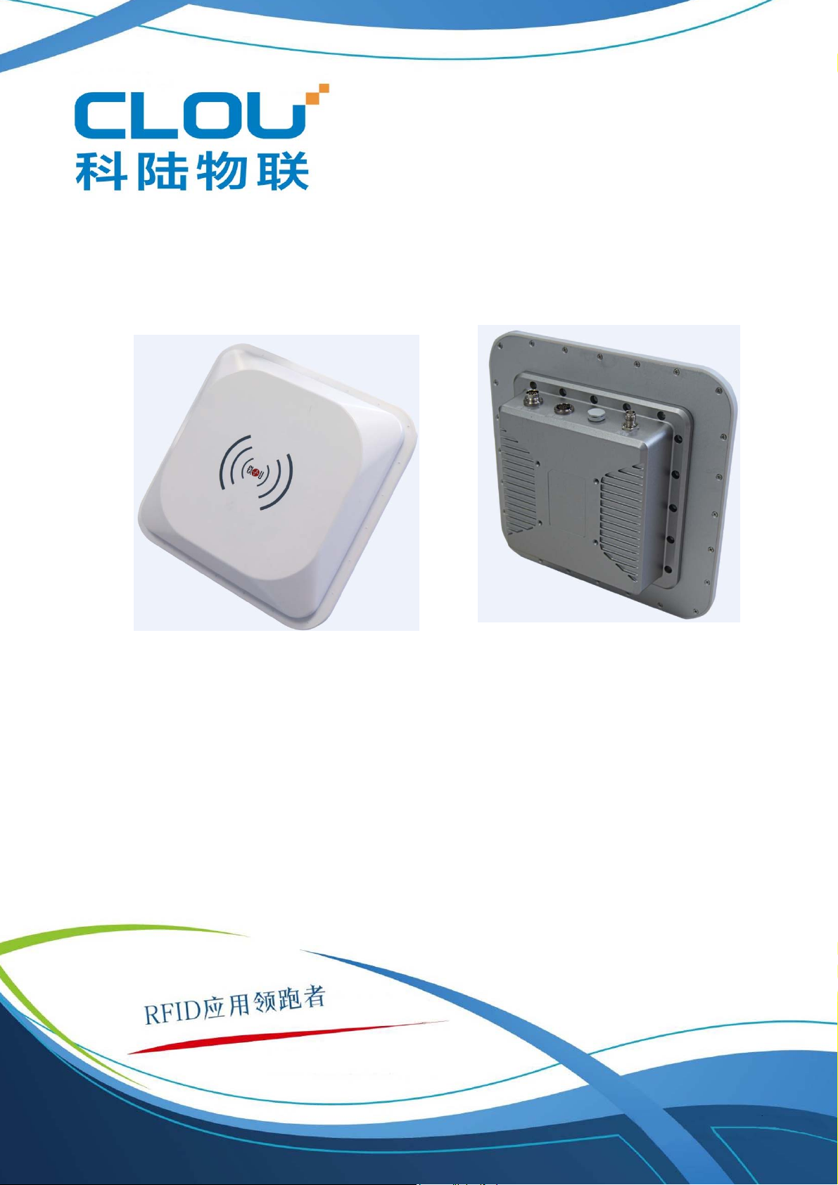
1.1, product features
CL7206B2 is a high performance RFID reader which ingrates reader module & antenna. It complies with
ISO18000-6C/6B protocols, working frequency support international main frequency bands: 902MHz ~928MHz,
860MHz ~865MHz,Export power adjustable. This device is featured by long range, high-speed reading, & high
accuracy, high sensitivity, strong anti-interference etc.
1.2.Main functions & performance
1.2.1 Main functions
EPC protocol:support ISO18000-6C\6B & EPC C1G2 V1.1 mandatory commands.
Built-in LINUX operation system.
Rich communication interface(Ethernet, RS232, RS485)
Built-in circular antenna, support one external antenna.
Support tag data filtering.
Support RSSI: can sense signal strength
Support RF output power adjusting.
working mode: FH/HH optional.
support antenna inspection function.
Support online & remote upgrade.
IO interface: 2 relay input & 2 relay output, wiegand output.
1.2.2 performance parameters
Working frequency: 902MHz ~928MHz, 860MHz~865MHz etc.
RF output power(port):33dBm±1dB(MAX)
Output power adjusting: 1 dB step
Reading tag range 0~10meters( related with tag, antenna & using environment).
Channel bandwidth:<200KHz
Integrated circular antenna VSWR:≤1.4:1
Integrated circular antenna gain:≥8dBi
RS232 communication rate: 115200bps(default), 19200 bps,9600bps
RS485 communication rate: 115200bps(default), 19200 bps,9600bps
Wiegand output support wiegand 66, 34 & 26 types.
Power supply(power adapter): AC input 100-240V,50-60Hz
DC output 24V±1.5V/2.5A
1.2.3.working environment
Working temperature scope: -20℃~+30℃
Working humidity: 5%~90%RH(+25℃)
Chapter II, Physical structure
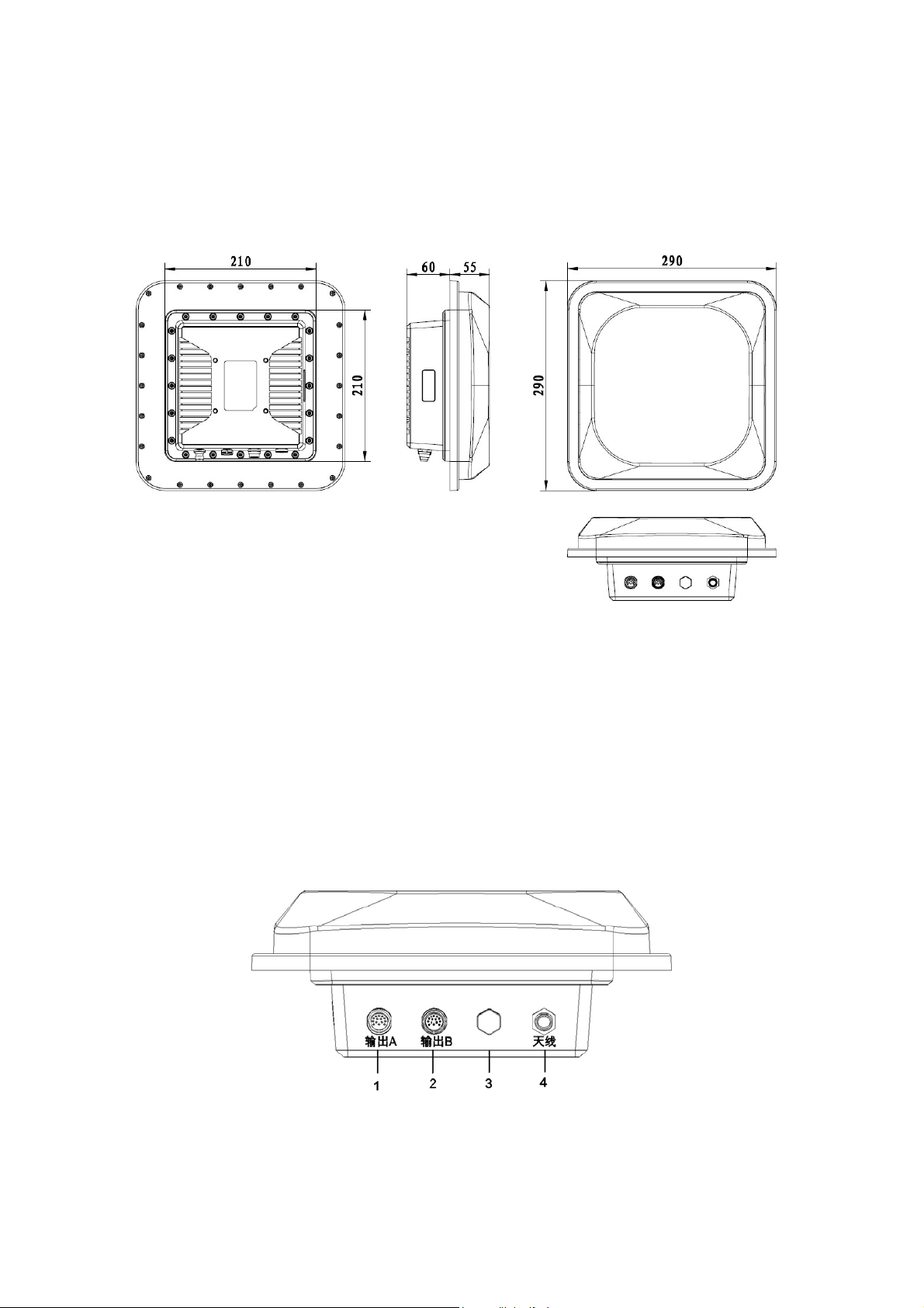
2.1 physical structure
Picture 2-1 CL7206B structure chart
Physical size: 290mm×290mm×115mm(accessories not included)
2.2 Weight
2.5kg(accessories not included)
2.3 I/O interface & communication interface chart
Picture 2-2 I/O & communication interface
1 — power & communication port
2 — I/O control interface
3 — Ventilation valve
4 — antenna port
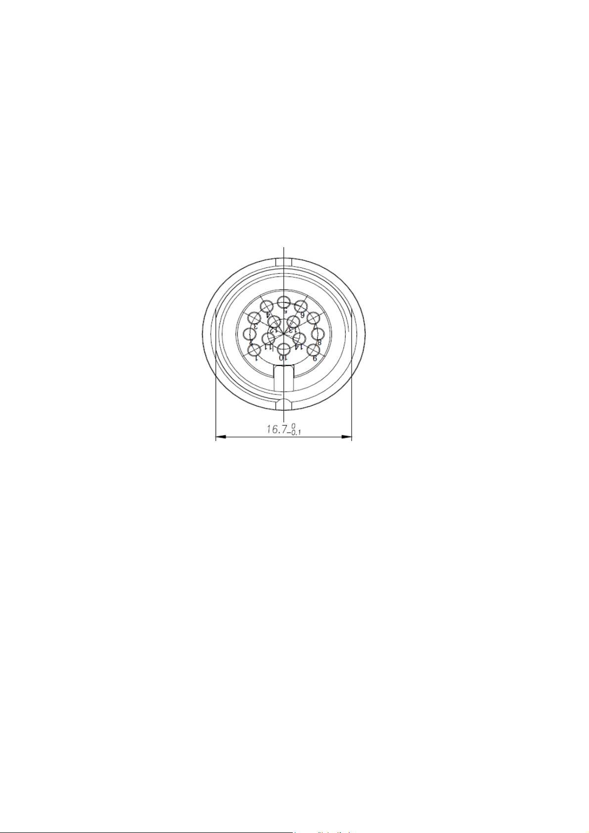
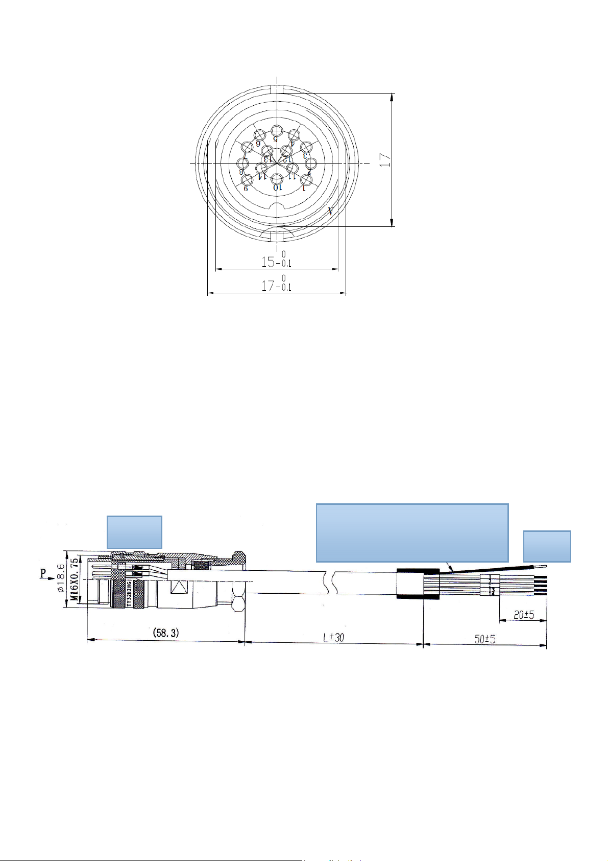
2.3.1 Power supply & communication interface description
Picture 2-3 power supply & communication port aviation port number chart
Aviation plug signal definitions
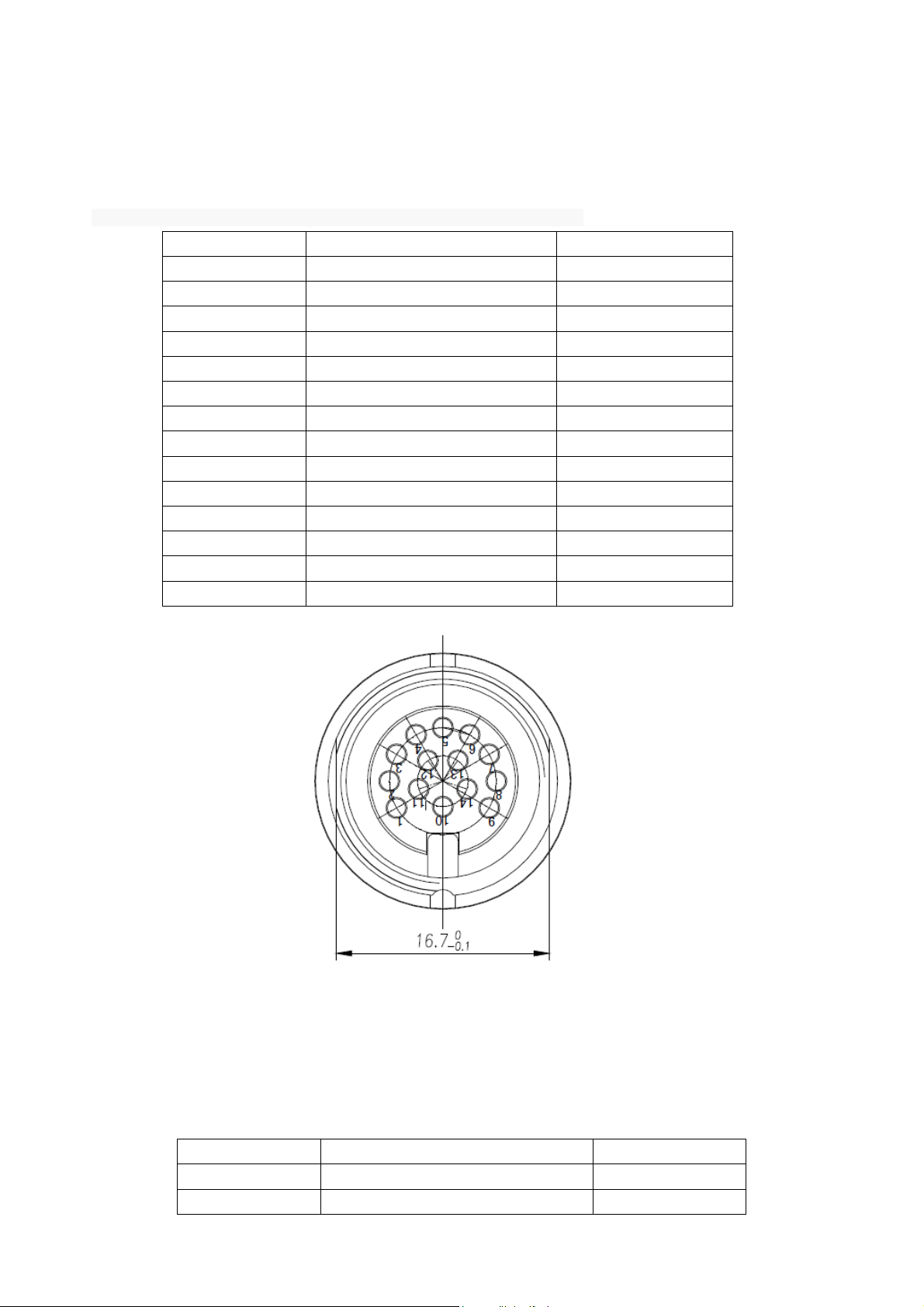
Chart 2-1 Power & communication interface signal definition
PIN Description PIN definition
1 Power supply GND PGND
2 Power supply GND PGND
3 24V power positive +24V
4 24V power negative +24V
5 NC NC
6 NC NC
7 NC NC
8 Ethernet port TD-
9 Ethernet port TD+
10 RS232 receiving RXD RX
11 S PGND
12 Ethernet port RD-
13 Ethernet port RD+
14 RS232 receiving RXD TX
2.3.2 I/O aviation port chart
Picture2-4 I/O interface aviation port number chart
I/O aviation port definition as per in chart 2-2:
Chart 2-2 I/O port signal function definition
PIN No. Description PIN definition
1 Relay 1 output port R1
2 Relay 1 output port L1
3 Relay 2 output port R2
4 Relay 2 output port L2
5 Optocoupler 1 external signal input
6 Optocoupler 2 external signal input
7 Optocoupler external signal input
8 Wiegand output 0 WG0
9 Wiegand output 1 WG1
10
11
12 RS485 signal 485+
13 RS485 signal 485-
14
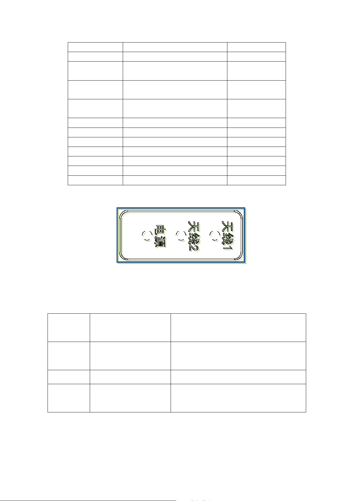
2.3.3 LED panel description
anode
anode
cathode
地
地
地
IN1
IN2
IGND
AGND
AGND
AGND
Picture 2-5 LED panel chart
LED panel description as per in chart 2-3:
Chart 2-3 LED definition description
LED Mark
Description Status description
No.
ANT1 Antenna 1 LED
ANT2 Antenna 2 LED Means built-in antenna successfully selected
PWR Read/write card status
Means external antenna port successfully
selected
Flickering means entering normal card reading
status.
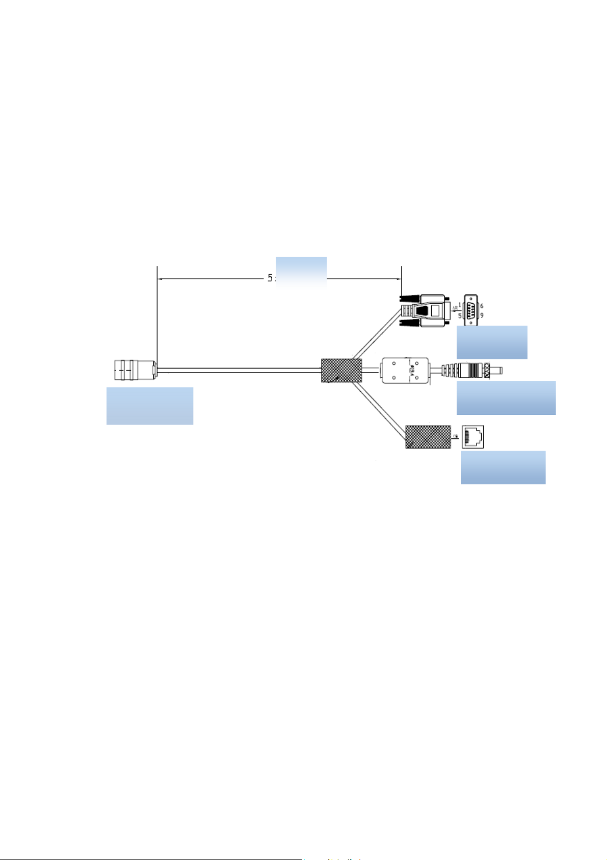
2.4 External cable connection description
2.4.1 power supply & communication cable description
Cable Specifications: Black insulated skin with metal screening net, 14 shares inner core, outer
diameter 7.8mm, main cable length is 4m, branch cables length are 1m. As shown in below picture, the
aviation plug connected with the reader "Power and communication interface," while 14 core lines are for
the three different signal path, i.e. "serial cable, DC power cord and network interface cable ", mainly used
for power supply and data transmission.
Aviation plug
Picture2-6 电源及通信接口线材分解示意
meter
RS232 port
Power supply port
Ethernet port
y
Picture2-7 Power supply & communication aviation plug chart
2.4.2 I/O control interface cable description
Cable Specifications: Black insulating skin with metal screening net, 14 shares inner core, outer diameter
7.8mm, the main cable length is 2.5m, "aviation plug “ is connected with reader "I / O control interface", 14
core lines mainly provides two-way optical coupling input port, two-way relay control ports, two Wiegand output,
two-way communication port 485. Mainly used for input trigger reading, peripherals switch control, upload
card data, and communication functions, see Table 2-4 I / O control aviation seat definition table.
Port A
Shielded wire are twisted into one and
covered b
heat shrink tubing.
Port B
Chart 2-8 I / O control interface cable chart
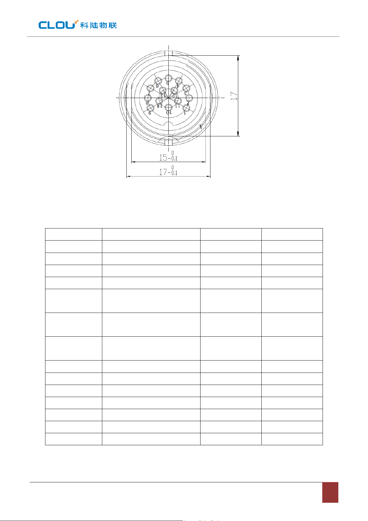
Chart 2-9 I/O control aviation seat illustration
The other end of the cable is bare and tin thread, can distinguish the functions defined by the color of the cable.
Chart 2-4 I/O control avaiation seat definition table
No. PIN description PIN Color Marking number
1 Relay 1 output port White 6
2 Relay 1 output port Blue 8
3 Relay 2 output port White/black 7
4 Relay 2 output port Blue/black 9
5 Optocoupler 1 external signal
Grey/black
input anode
6 Optocoupler 2 external signal
Grey
input anode
7 Optocoupler external signal input
purple/black
cathode
8 Wiegand output 0 purple 2
9 Wiegand output 1 Green/black 1
10 Ground Green 10
5
4
3
11 Ground Yellow/black 14
12 RS485 signal Yellow 13
13 RS485 signal Red/black 12
14 Ground Red 11
2.4.3 External RF cable description
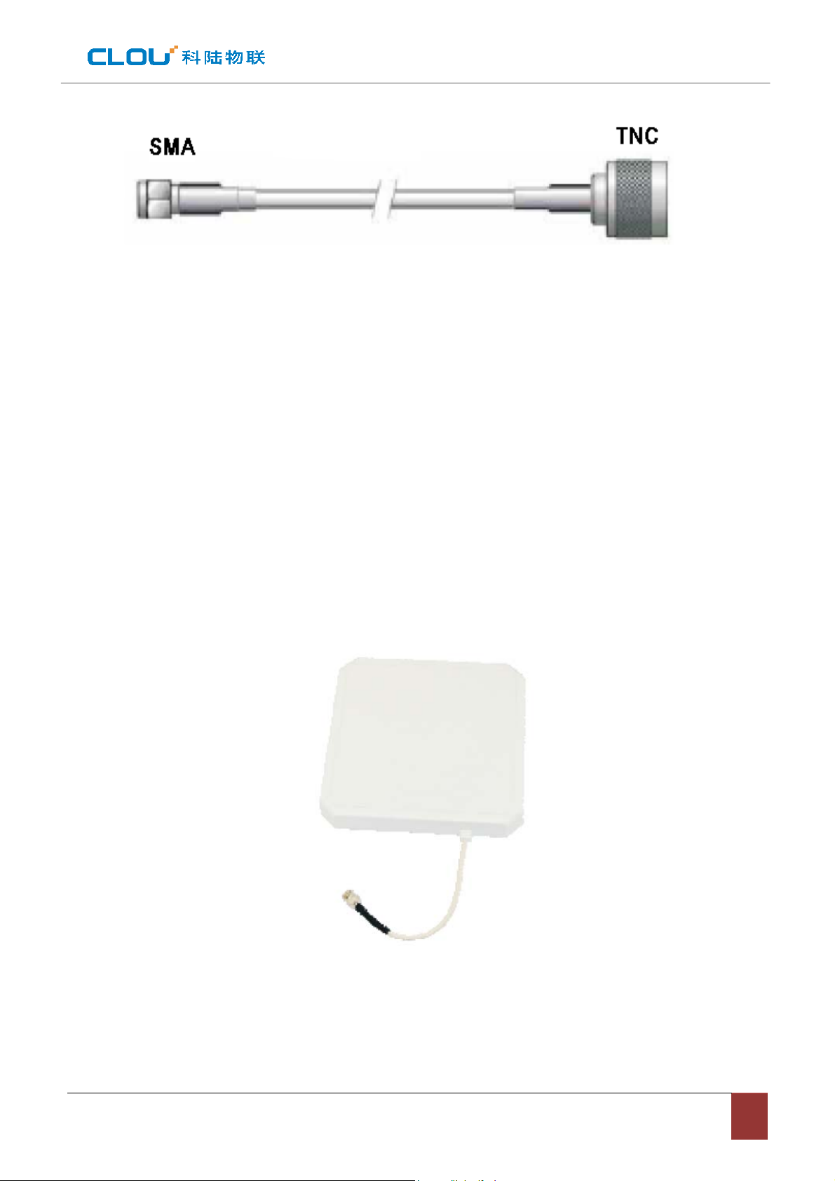
Picture 2-10 RF cable schematic chart
The connector between RF cable & reader is TNC male, the connector between RF cable & antenna
is SMA male connector (depending on antenna connector as well). Try to keep the cable length within
5meters, impedance 50Ω, the insertion loss less than 2dB. Of course, you can choose a
high-performance cable, appropriately increase the length, but keep the insertion loss less than 2dB.
Note: Too long RF cable or cable poor connection will cause high signal attenuation & poor reader
performance.
2.4.4 External antenna description (optional)
This reader has a integrated circular antenna. User can also connect one more external antenna. It is
recommended to use the external antenna provided by our company.
Picture 2-11 Circular antenna

Antenna performance parameters:
Work frequency: 902~928 or 860~865 MHz
Gain: 8 dBic
Maximum VSWR: 1.3:1
Polarization: L Circular Right or left
Input impedence: 50 Ohms
Weight: 2.3lbs
Mechanical size: 10.2” x 10.2” x 1.32”
Antenna Connection: coax pigtail, Rev INC Males
Working temperature: -20℃~30℃
Lightning protection: DC grounded
Environmental rating: IP54
2.4.5 Network connection chart
Ethernet connection is used for long range high speed connection (within 80meters). Can connect
through router or exchanger or PC Ethernet port. Refer to below picture.
 Loading...