

Page 1
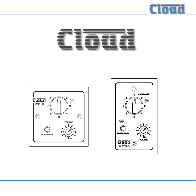
WP-8 and WP-8A Headphone Stations
Installation Guide
Page 2

WP-8 Installation Guide
2
Page 3

Contents
Safety Information ........................................................4
Introduction ...................................................................4
What’s in the Box .................................................................................... 5
Top view ..................................................................................................... 6
Rear view ................................................................................................... 7
Installation .....................................................................8
Mechanical ................................................................................................. 8
Connections .............................................................................................. 8
Operation .................................................................... 15
WP-8 Installation Guide
3
Page 4
Safety Information
The Cloud WP-8 contains no active electronics and thus requires no AC or
DC voltage supply. Safety precautions are therefore minimal.
Introduction
The WP-8, part of the Cloud Headphone Distribution System, is a remote
headphone station that connects to an output of either a CAM-16 Audio
Distribution Matrix or a CAS-16 Audio Distribution Sub-Station, using
standard CAT-5 cable. In addition to a stereo headphone socket for
connection of a pair of personal headphones, it has controls allowing a user
to select the music source (from those connected to the CAM-16), and to
adjust the headphone volume. It also provides outputs for a pair of small
loudspeakers; these can also be used to feed the inputs of an external power
amplier or powered speakers. When used in this way, the panel’s controls
also set the source and level for the external equipment.
The WP-8 ts standard UK-style single-gang electrical back boxes, either
surface-mounting or ush-tting. Recommended back box depth is 25 mm.
Two M3.5 x 20 xing screws are supplied with each WP-8 plate.
WP-8 Installation Guide
4
Page 5

US Versions:
The WP-8A is electrically and functionally identical, but the faceplate has
different physical dimensions (4.51” x 2.76”) which allows it to be mounted
into a standard single-gang US-style back box (with vertical orientation).
All information in this manual applies equally to both mechanical versions.
What’s in the Box
Please check the box for damage before opening. If there is damage, please
contact your Cloud agent and the shippers.
The box should contain the following items:
• WP-8 or WP-8A Headphone Station
• 2 qty M3.5 x 20 panel xing screws*
• This manual
* Not supplied with WP-8A
WP-8 Installation Guide
5
Page 6

Top view
2
1
1. Headphone socket
2. Music source selection switch
3. Headphone volume control
WP-8 Installation Guide
6
3
Page 7

Rear view
5
4
4. IDC connector block for hard-wiring
5. Screw-terminal block for external amplier/speaker connection
WP-8 Installation Guide
7
Page 8

Installation
Mechanical
The Cloud WP-8 is designed to be wall mounted. It is the same physical size
as a UK-style single-gang electrical plate and can be ush-mounted in the
back box provided, or in a standard surface box with a minimum depth of
25 mm. Fixing screws are provided.
The WP-8A, the US variant of the WP-8, ts a standard US-style electrical
box.
Connections
The only electrical connection required is a single CAT-5 cable. This
is terminated on the WP-8’s rear PCB at an 8-way IDC (Insulation
Displacement Connector) connection block.
Note that the total cable run from the CAM-16 or CAS-16 to a WP-8 should
not exceed 100 m.
WP-8 Installation Guide
8
Page 9

First pass the CAT-5 cable through a suitable hole in the back box. Using an
IDC insertion tool, connect it to the 8-way IDC block as follows:
TERMINAL CAT-5 CORE
1 Brown
2 White + Brown
3 Green
4 White + Blue
5 Blue
6 White + Green
7 Orange
8 White + Orange
We recommend that some form of cable retention is employed to secure
the CAT-5 cable to the back box; a cable tie with an adhesive cable tie base
will normally be adequate. Stick the base to the inside of the box if there is
room, or to the rear of the box if it is of the cavity wall xing type.
WP-8 Installation Guide
9
Page 10

Connecting an external amplier and/or speakers
The WP-8 is provided with additional outputs, which can be used to drive
external low-power loudspeakers directly, active loudspeakers or the line
inputs of an external amplier. Both stereo and mono congurations are
possible.
Connections are made to the 6-way screw-terminal block 5 on the rear
PCB. The pinout of this connector block is as follows:
PIN MARKED CHANNEL PURPOSE
1 0V
2 L+ Switched output +
3 L+ Permanent output +
4 0V
5 R+ Switched output +
6 R+ Permanent output +
LEFT
RIGHT
Output – (0 V)
Output – (0 V)
Note that both ‘switched’ and ‘permanent’ outputs are available. The switched
outputs are wired internally via switch contacts on the front panel headphone
WP-8 Installation Guide
10
Page 11

socket, and mute when a jack plug is inserted in the socket. The permanent
outputs are continuously active.
The WP-8’s external outputs can provide 150 mW of power in stereo or
300 mW in mono, into 8 ohm speakers. (The impedance of the speakers is
not critical.)
NOTE: Take care when wiring a WP-8 since wiring errors can cause
incorrect operation.
WP-8 Installation Guide
11
Page 12

Connecting loudspeakers – stereo operation
Connect the loudspeakers as shown in Fig. 1 if continuous operation is
required, or as in Fig. 2, if the speakers should mute when headphones are
connected.
WP-8 Installation Guide
12
Page 13

Connecting loudspeakers – mono operation
Outputs may be paralleled if a single mono output is required. Connect the
loudspeaker as shown in Fig. 3 if continuous operation is required, or as in
Fig. 4, if the speaker should mute when headphones are connected.
WP-8 Installation Guide
13
Page 14

Driving powered loudspeakers or external ampliers
A line level signal may be derived from the outputs by the addition of 1k ohm
resistors; this may be used to drive active loudspeakers or the inputs of a
separate external amplier. Again, either stereo or mono operation may be
employed. Use the wiring shown in Fig. 5 (continuous) or Fig. 6 (switched) for
stereo operation, or Fig. 7 (continuous) or Fig. 8 (switched) for mono operation.
WP-8 Installation Guide
14
Page 15

Operation
The WP-8 has a 3.5 mm 3-pole jack socket for headphones 1. The WP-8 is
suitable for headphones having an impedance of 32 ohms. We recommend
the Cloud CP32 headphones for use with the headphone distribution
system.
The music source can be selected (from those available) with the source
selection switch 2 and the headphone volume adjusted with the level
control 3.
WP-8 Installation Guide
15
Page 16

Cloud Electronics Limited
140 Staniforth Road
Shefeld S9 3HF
England
Tel: +44 (0)114 244 7051
Fax: +44 (0)114 242 5462
email: info@cloud.co.uk
web: www.cloud.co.uk
 Loading...